EP0681448B1 - Method and device for continuously measuring blood pressure - Google Patents
Method and device for continuously measuring blood pressure Download PDFInfo
- Publication number
- EP0681448B1 EP0681448B1 EP94905746A EP94905746A EP0681448B1 EP 0681448 B1 EP0681448 B1 EP 0681448B1 EP 94905746 A EP94905746 A EP 94905746A EP 94905746 A EP94905746 A EP 94905746A EP 0681448 B1 EP0681448 B1 EP 0681448B1
- Authority
- EP
- European Patent Office
- Prior art keywords
- blood pressure
- signal
- subject
- pressure
- sphygmomanometer
- Prior art date
- Legal status (The legal status is an assumption and is not a legal conclusion. Google has not performed a legal analysis and makes no representation as to the accuracy of the status listed.)
- Expired - Lifetime
Links
Images


Classifications
-
- A—HUMAN NECESSITIES
- A61—MEDICAL OR VETERINARY SCIENCE; HYGIENE
- A61B—DIAGNOSIS; SURGERY; IDENTIFICATION
- A61B5/00—Measuring for diagnostic purposes; Identification of persons
- A61B5/02—Detecting, measuring or recording pulse, heart rate, blood pressure or blood flow; Combined pulse/heart-rate/blood pressure determination; Evaluating a cardiovascular condition not otherwise provided for, e.g. using combinations of techniques provided for in this group with electrocardiography or electroauscultation; Heart catheters for measuring blood pressure
- A61B5/024—Detecting, measuring or recording pulse rate or heart rate
- A61B5/02438—Detecting, measuring or recording pulse rate or heart rate with portable devices, e.g. worn by the patient
-
- A—HUMAN NECESSITIES
- A61—MEDICAL OR VETERINARY SCIENCE; HYGIENE
- A61B—DIAGNOSIS; SURGERY; IDENTIFICATION
- A61B5/00—Measuring for diagnostic purposes; Identification of persons
- A61B5/02—Detecting, measuring or recording pulse, heart rate, blood pressure or blood flow; Combined pulse/heart-rate/blood pressure determination; Evaluating a cardiovascular condition not otherwise provided for, e.g. using combinations of techniques provided for in this group with electrocardiography or electroauscultation; Heart catheters for measuring blood pressure
- A61B5/021—Measuring pressure in heart or blood vessels
- A61B5/022—Measuring pressure in heart or blood vessels by applying pressure to close blood vessels, e.g. against the skin; Ophthalmodynamometers
-
- A—HUMAN NECESSITIES
- A61—MEDICAL OR VETERINARY SCIENCE; HYGIENE
- A61B—DIAGNOSIS; SURGERY; IDENTIFICATION
- A61B5/00—Measuring for diagnostic purposes; Identification of persons
- A61B5/72—Signal processing specially adapted for physiological signals or for diagnostic purposes
- A61B5/7203—Signal processing specially adapted for physiological signals or for diagnostic purposes for noise prevention, reduction or removal
- A61B5/7207—Signal processing specially adapted for physiological signals or for diagnostic purposes for noise prevention, reduction or removal of noise induced by motion artifacts
- A61B5/721—Signal processing specially adapted for physiological signals or for diagnostic purposes for noise prevention, reduction or removal of noise induced by motion artifacts using a separate sensor to detect motion or using motion information derived from signals other than the physiological signal to be measured
Definitions
- the field of the invention is that of measuring the blood pressure of a subject, and more generally any information representative of the behavior of the heart of a subject. More specifically, the invention relates to a device allowing the measurement of continuous blood pressure, and possibly heart rate (function pulsemeter).
- the principle of the measurement consists in gradually loosening the tourniquet.
- the sensor does not detect any signal.
- SBP systolic pressure
- DBP diastolic pressure
- Sphygmometers have many drawbacks. They are relatively bulky and expensive. They require a complex operating procedure (tightening / loosening) which limits its use to the medical field. They also can hardly be worn by a subject at all times, unless the subject is kept on a hospital bed.
- sphygmometers only provide information punctual, and do not allow easy monitoring of blood pressure. So when he is necessary to monitor a subject, we use automatic systems, which control the use of a sphygmometer at regular intervals, and for example every 10 minutes. These very long intervals can cause loss of information, such as passenger blood pressure peak.
- the transit time between the start of the wave generated by the core is measured by the difference in electrical potential between a given point on the body which can be a finger and the wrist of the other hand.
- the pulse generated by the cardiac overpressure is detected by measurement of the amount of hemoglobin at a given time.
- a beam of light generated by a light emitting diode crosses a blood vessel then a detector photosensitive receives a fraction of the reflected light.
- This blood pressure monitor is of very little ergonomic use. It is presented under the shaped like a watch worn on a wrist. To make a measurement, it is necessary to place one or two fingers of the other hand on places provided for this purpose. This handling is not so simple, and leads, like the sphygmometers, to a punctual measurement of tension.
- the invention particularly aims to overcome these various drawbacks of the state of the art.
- a pressure sensor is applied to the body of the wearer, and a finding the minimum and maximum peaks of the signal delivered by the sensor makes it possible to deliver information representative of systolic and diastolic pressures.
- a first objective of the invention is to provide a device blood pressure monitor continuously measuring a subject's blood pressure.
- the invention also aims to provide such a tensiometer which allows control changes in the subject's tension.
- Another object of the invention is to provide such a tensiometer, which is comfortable and user friendly.
- the invention aims to provide such a blood pressure monitor, which requires no manipulation or control particular.
- the tensiometer of the invention must be able to operate in continuously independently. Furthermore, it must be compact, and not cause no discomfort for the wearer.
- Another object of the invention is also to provide such a tensiometer, which is of a low cost price, and which is easily industrializable.
- the blood pressure can be permanently known (or at regular intervals), without any manipulation.
- the measurement performed is relative, but the actual pressure is determined from the reference information.
- said sensor comprises a first piezoelectric element reacting in flexion and / or in traction / compression to the displacements of a first sensor-plate in direct contact with the body of said subject and producing a first potential difference as a function of said displacements of the first sensor-plate.
- This sensor has the particular advantage of a small footprint and a good sensitivity.
- the blood pressure monitor advantageously comprises a second piezoelectric element compensation reacting in bending and / or in traction / compression to displacements a second plate sensor isolated from the body of said subject and producing a second potential difference as a function of said displacements of the second sensor-plate.
- said first and second piezoelectric elements are substantially identical and placed in spaced overlap. So they undergo substantially the same movements.
- said first and / or said second piezoelectric elements are placed above and / or below a recess formed in a printed circuit and fixed to said printed circuit by their ends, using conductive glue.
- said first and / or said second piezoelectric elements is maintained by the one of its two ends, the second end being free.
- the sphygmomanometer may comprise two substantially identical piezoelectric elements and placed substantially opposite.
- Said first plate sensor advantageously acts on said first piezoelectric element by the intermediate d a spring.
- the device comprises means for measuring the pressure application of said sensor to the body of said subject, delivering a signal representative of said application pressure, and said processing means correct said information representative of the blood pressure as a function of said signal representative of the pressure of application.
- this pressure can vary over time. However, it should not not induce modifications on the interpretation of the measured signal.
- the device comprises means of positioning and / or fixing by clamping in contact with the body of said subject of said case, such as a bracelet.
- said measurement means comprise for example a displacement reacting to the tension of said positioning and / or clamping means.
- the tensiometer of the invention also includes means for determining the heart rate of said subject.
- said means for calculating the heart rate include means for determining the fundamental period of said signal representative of instantaneous blood pressure, such as filtering means multichannel comprising a plurality of filters each having a frequency band separate, and filter detection means corresponding to said period of the fundamental.
- the blood pressure monitor invention may also include means for determining information representative of the respiratory period and / or d information representative of the respiratory amplitude of said subject.
- the invention therefore relates to the continuous and autonomous measurement of the blood pressure of a subject.
- the invention is based on a new approach for those skilled in the art, based on the detection of variations in the blood pressure of the subject, constantly.
- the tensiometer of the invention operating continuously (i.e. at intervals regular, which can vary from a few seconds to a few minutes), it must be portable, autonomous, of limited weight, and operate without user intervention.
- the device of the invention is presented under the shape of a wristwatch.
- the invention can take place in a reduced size case, which must be placed in contact with the subject's skin.
- FIG 1 illustrates the general principle of the device of the invention.
- a sensor 11 intended to be applied against the body of the subject, detects the pressures 12 of the part of the body where it is applied.
- the sensor 11 delivers a signal electric 13, representative of these pressures.
- the sensor 11 therefore detects on the one hand the movements of the subject, and on the other hand the pressures of the skin corresponding to the variations in blood pressure in a blood line near the sensor.
- the signal 13 includes in particular a information representative of variations in blood pressure.
- the device of the invention is not perfectly immobilized against the subject's body, for example using adhesives ... (this is particularly the case if the device is attached to the arm by a bracelet): the pressure applied by the case to the skin may vary, either because it moves slightly, or because the tightening changes (in the case of a bracelet, it can slide along the wrist towards a place where the wrist circumference is smaller. The pressure is then less).
- the device of the invention proposes to take into account information 18 representative of this pressure carried out by the housing. He can by example it is a measure of tightness of the bracelet.
- the variation signal amplitude is directly related to blood pressure. You just need to make a amplitude measurement of the signal from the sensor to obtain information on the pressure arterial by ensuring the stability of the stress induced by the bracelet.
- the blood pressure information 16 is relative data (dependent including the subject carrying the blood pressure monitor).
- the device of the invention comprises means 19 for determining the blood pressure, which determine the values 17 of the systolic and diastolic pressures, from reference data 110 stored in storage means 111.
- These data reference 110 were obtained from 112 measurements made (once and for all, at less as long as the subject's condition does not change significantly) using a sphygmometer classic.
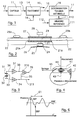
- FIG. 2 represents (in section) a first example of an activity sensor which can advantageously be used in the device described above.
- An element 21 made of piezoelectric ceramic is bonded by its two ends 21 A , 21 B to a printed circuit 22, in which it has previously been formed one day 23 allowing the element 21 to deform.
- This element 21 has for example a size of 12 x 4 x 0.7 mm.
- the sensitivity of this piezoelectric cell 21 is understood between 1.3 and 13 kPa (between 1 and 10 mmHg).
- a wedge 24 is fixed, by gluing, to the center of the element 21.
- a plate 25 of aluminum, or any other material On the wedge 24 takes place a plate 25 of aluminum, or any other material.
- This plate 25 which may have a surface of 7 x 7 mm, is in contact with the skin 26 of the subject, when the device is in place.
- the large contact surface allows to obtain a signal of movement of strong power.
- the senor comprises a second group of piezoelectric elements 27 and plate 28, isolated from the body.
- the free plate 28 provides a signal reflecting arm movements, movements that induce useless signals (noise) in the first sensor.
- a reduction of these parasites can be obtained by combining the signals delivered by the two elements 21 and 27 (subtraction of the second from the first).
- the second group or “parasitic noise sensor” can also be positioned in a different way, at the level of the fixing of the bracelet on the case. Ceramic then works in tension-compression, and no longer in bending, and thus captures better disturbances produced by pressure variations on the first sensor (always applied to the skin) while being isolated from the useful signal (heart rate).
- the two bimetallic strips (or piezoelectric elements) 21 and 27 are identical and compensated for acceleration. They are mounted in opposition.
- the elements 21 and 27 are bonded directly, by their ends, to the printed circuit 22, using a conductive glue.
- a conductive glue no means of wedging or fixing is necessary, nor any wiring means.
- Other, more conventional techniques can also be used.
- the various electrical circuits are advantageously components 29 A , 29 B mounted on the surface (SMD).
- the sensor can therefore be represented, electrically, by the equivalent diagram of Figure 3, associated with amplifiers.
- the cells 21 and 27 correspond to two capacitors in series 31 and 32.
- the signal 33 taken from the capacitor 32 is amplified by the amplifier 34, which delivers a signal 35 representative of the subject's movements.
- the signal 36 taken from the capacity 31 is also amplified by a amplifier 37 delivering a signal 38 corresponding to the movements and variations blood pressure.
- the signal 35 (movements) is subtracted from signal 38 (movements + blood pressure) by a differentiator 310.
- the signal 35 is transmitted (311) to the processing means.
- signal 13 of Figure 1 corresponds to the combination of signals 39 and 311.
- G1 and G2 gains are different because the sensitivities of the two sensors are different: the fact that the second piezoelectric cell is isolated, while the first undergoes wrist pressure.
- G3 gain is chosen to deliver a signal with good dynamics for analog / digital conversion.
- FIG. 11 illustrates another advantageous arrangement of the sensors of the device of the invention, according to which the piezoelectric cells 111 and 112 are no longer superimposed, but placed opposite. They are each maintained by the one of their ends 113, 114, for example by molding in the chassis 115 of the device. L the other end 116, 117 of each cell is free.
- a plate 118 is placed in contact with the skin 119 of the wearer. It is connected to cell 111 by a spring 1110, thereby transmitting the movement of the skin to it.
- a 1111 plate is placed on the end 117 of the second cell 112, which acts as a noise sensor, so that the movements detected are similar to those undergone by the first cell 111.
- Pressure sensors 1113 and 1114 placed between the skin 119 and the bottom of the case 1115 make it possible to measure the tightening pressure of the bracelet. They advantageously allow ensure reliable measurement of clamping pressure fluctuations up to at 4 kPa (30 mm Hg).
- These are for example registered resistors, such as MOTOROLA (registered trademark) resistors referenced MPX2040D.
- Piezoelectric cells can be made from PXE ceramic 5 distributed by RTC (registered trademark).
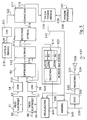
- FIG. 4 schematically shows a device according to the invention, at wristwatch format.
- the overall device is advantageously integrated in a case 41 held on the wrist using a bracelet 42.
- the detection of the stress 45 can be done using a force sensor or a less sensitive pressure sensor than the blood pressure sensor (e.g. a piezoresistive gauge), or using a displacement sensor knowing that it is function of the stress applied to the wrist (the elongation of the bracelet corresponds effect at the position of the bracelet, therefore at the pressure made by the wrist on the sensor).
- a force sensor or a less sensitive pressure sensor than the blood pressure sensor e.g. a piezoresistive gauge
- a displacement sensor knowing that it is function of the stress applied to the wrist (the elongation of the bracelet corresponds effect at the position of the bracelet, therefore at the pressure made by the wrist on the sensor).
- a displacement sensor is fixed on the one hand to the housing 41, and on the other hand to bracelet 42.
- the voltage undergone by this sensor is directly representative of the tightening.
- a first piezoelectric element 51 therefore detects displacements 52 corresponding to movement and blood pressure. It generates an electrical signal correspondent 53 which is digitized, using an analog / digital converter (ADC) 54.
- ADC analog / digital converter
- a second piezoelectric element 55 detects movements alone 56.
- the corresponding electrical signal 57 is also digitized by the converter analog / digital 58.
- the two ADCs 54 and 58 sample the signals for example at a rate of 64 measurements / s. They can advantageously constitute two channels of a converter also responsible for the conversion of the tightening stress.
- the difference 59 is then made between the digital signals 510 and 511, to obtain the digital signal 512 representative of the arterial pressure alone.
- the signal 512 is therefore transmitted to a module 513 for linearization, for filtering.
- low pass and / or adaptive filtering finding and removing correlations between signals 511 and 512
- Scaling involves multiplying the value received by a sensitivity coefficient representative of the device.
- the signal correspondent 514 may for example be as shown in FIG. 6.
- a sensor 519 of tightening (or pressure) delivering a signal 520 which is digitized (521) before being transmitted (522) to the correction module 517.
- the information 518 representative of the relative blood pressure is then transmitted to a module 538 for calculating the absolute blood pressure.
- a module 538 for calculating the absolute blood pressure.
- the 540 module is not a simple memory. He also performs treatment of initialization, intended to calculate information 539 from data 541 of tension measured externally.
- This module 538 therefore finally delivers the information 542 on blood pressure, including systolic (SBP), diastolic (DBP) and possibly average (MBP).
- SBP systolic
- DBP diastolic
- MBP possibly average
- This information 542 can be stored in a memory 543, and also displayed, using a display screen 544, for example with crystals liquids.
- rhythm heart or pulse
- This operation consists in measuring the period of the fundamental (61, figure 6) contained in the signal arterial pressure.
- the analysis strip is narrow and that there is only fundamental research, a 523 multichannel filtering approach is desirable.
- the analysis band is from 30 beats / s to 240 beats / s, i.e. 0.5Hz to 4Hz.
- This method has the particularity of consuming little memory capacity and in number of operations to be executed taking into account the frequencies of each channel 524 1 to 524 N which can be 0.5 0.66 0.8 1 1.33 2 4 Hz, corresponding to heart rates of 30, 40, 48, 60, 80, 120 and 240 beats / min.
- Each channel corresponds to a sub-multiple flow rate of the maximum rate. Thus, only one filter template is used.
- the signal energy and the period of the filtered signal are calculated (525) by counting. We thus obtain a spectrum of energy lines and a function of calculated periods.
- a selection strategy 525 determines the most reliable channel, and delivers the corresponding information 526 which can also be stored (543) and / or displayed (544).
- the start of each is selected pulse period.
- the differences in value of the different periods can be corrected by averaging.
- An average curve is obtained which is easy to use. We deduce in particular the values of the extrema and the average arterial pressure.
- D other physiological data can also be deduced from the blood pressure signal, in particular with regard to respiratory parameters.
- respiration modulates l amplitude of the blood pressure signal 121.
- the treatment consists in seeking the maxima of the blood pressure signal (amplitude and coordinates over time). Then, we delete the average value and, by detecting the zero crossings of the signal, we calculate the respiratory period and its inverse, the frequency. Over the duration of this period, the average value of the rectified signal is calculated, which is a good image of the respiratory range. This analysis is done for example on a window of about 8 seconds.
- the stored data 531 makes it possible to perform statistics 532, including the 533 results can be viewed, but above all used in a 534 module of prediction. It is thus possible to generate an alarm signal 535, producing a signal sound 536, when changes in blood pressure and / or heart rate and / or of breathing has dangerous characteristics for the subject. It is to highlight that this prediction module is very important, because these are not the absolute values of the signals but their changes over time which are significant.
- the device may include connection means 537, which allow the content of memory 530 to be transmitted to an external treatment unit.
- the link can be wireless.
- the HF link can implement a modulation of amplitude (ASK mode).
- L transmitter in the housing
- L transmitter for example comprises a local oscillator with surface wave vibrating at 224.5 MHz.
- l antenna d emission is of reduced dimensions (a few cm side) and can be performed on the printed circuit.
- l transmitter After the transmission of a measure, l transmitter is put on standby, which reduces current consumption.
- the power of transmitter can be less than 5 mW and its range by a few meters.
- r be a function representative of the pressure drop seen by the sensor (r is a complex function due to the consistency of the muscles, the condition of the ducts ).
- r is a function of the constraint of fixation but not of the variation of the structure between the sensor and the blood conduit, because the constraint (c) of absolute fixation is great in front of the variations of structure of the wrist during movement. So the function r can be known and is unique. We can therefore determine the relationship between the fixation constraint c and r for a given patient. Thus SBP and DBP can be reached by knowing the variation of c. For get the true pressures then simply reference the sensor at a given time to from a standard blood pressure monitor.
- Y q * (SBP-DBP) with q calibration factor as well as the form coefficient k.
- Figures 7 and 8 show typical examples of variations in Y and k respectively, as a function of c.
- k is related to the structure supporting the sensor and the characteristics of the blood vessels.
- the evolution of k is linked to the person's state of health.
- the relation (6) shows that the value of k is between 0.66 and 1. In case of variation of k, the device establishes a correction on Y.
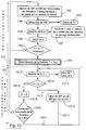
- the calculation process according to the invention comprises two phases: an initialization phase 101 and an operating phase in continuous 102.
- the initialization phase 101 takes place in principle only once, during the acquisition of the blood pressure monitor. It consists in personalizing this blood pressure monitor to the subject, by based on its physiological characteristics.
- the tensiometer of the invention is assigned to a person given. If the carrier changes (for example in the case of a doctor prescribing the wearing of shows it to different patients successively), it is necessary to resume the phase initialization. The same is true if the physiological characteristics of the subject (i.e. his state of health) evolve.
- SBP and DBP blood pressure measurement
- an external blood pressure monitor reference such as a conventional sphygmometer.
- SBP and DBP blood pressure measurement
- the measured data SBP and DBP are then introduced into the tensiometer of the invention, for example using one or more several input buttons placed on the box.
- MBP mean arterial pressure
- two measurements are taken 106 instant blood pressure over a predetermined period of time for two tightening constraints c of known values.
- the amplitude of Y of the signal is determined (107), identifying the extremes in the measured signal, as has already been described.
- the minimum of this signal is DBP, and the maximum is SBP.
- the stabilized pressure is also determined from this signal, corresponding to the moment when the effect of the overpressure of the heart is finished. This value corresponds to MBP. From these three values determined on the signal, we can calculate (108) a second coefficient of form k, still in accordance with equation (2).
- the determination of the function can for example correspond, in practice, to a selection of a function from a set of pre-recorded functions.
- This determination 1011 ends the initialization phase 101.
- a measurement 1012 is regularly carried out instantaneous blood pressure, using piezoelectric sensors (measures 39 and 311, Figure 3) and the tightening stress (measure c).
- the invention can find applications in many fields. She can for example be used as a sphygmomanometer. In this case the wearer can follow his heart activity for his personal information or the information may be transmitted to an external processing unit, by telephone links or radioelectric. In the latter case, the sensor worn as a watch may include a small transmitter and act as an alarm via a relay connected to the network telephone.
- a medical application is for example the continuous monitoring of blood pressure arterial (awareness of the shape of the blood pressure wave and its value).
- the blood pressure monitor can also be used to detect drowsiness.
- This guy application can have opportunities in many sectors (driving, work or monitoring station).
- the state of drowsiness is a transitional state between waking and light slow sleep or stage 1. Cardiac activity is changed and treatment new information entered by an easily portable sensor would be greatly appreciated.
- the validation of the detection can be carried out by an EMR with electrodes detecting the rapid movement of the eyelids which is a reflection of drowsiness.
- the invention can also be used in a device for recognizing sleep phases, such as that described in the joint application entitled “Sleep device recognition of sleep phases, and corresponding application ", bearing the number FR-2 700 689.
Landscapes
- Health & Medical Sciences (AREA)
- Life Sciences & Earth Sciences (AREA)
- Cardiology (AREA)
- Medical Informatics (AREA)
- Surgery (AREA)
- Biophysics (AREA)
- Pathology (AREA)
- Engineering & Computer Science (AREA)
- Biomedical Technology (AREA)
- Heart & Thoracic Surgery (AREA)
- Physiology (AREA)
- Molecular Biology (AREA)
- Physics & Mathematics (AREA)
- Animal Behavior & Ethology (AREA)
- General Health & Medical Sciences (AREA)
- Public Health (AREA)
- Veterinary Medicine (AREA)
- Vascular Medicine (AREA)
- Ophthalmology & Optometry (AREA)
- Measuring Pulse, Heart Rate, Blood Pressure Or Blood Flow (AREA)
Description
Le domaine de l'invention est celui de la mesure de la tension artérielle d'un sujet, et plus généralement de toute information représentative du comportement du coeur d'un sujet. Plus précisément, l'invention concerne un dispositif permettant la mesure de la pression artérielle en continu, et éventuellement du rythme cardiaque (fonction pulsemètre).The field of the invention is that of measuring the blood pressure of a subject, and more generally any information representative of the behavior of the heart of a subject. More specifically, the invention relates to a device allowing the measurement of continuous blood pressure, and possibly heart rate (function pulsemeter).
La connaissance de la pression artérielle, et éventuellement du rythme cardiaque, intéresse de très nombreux utilisateurs. On peut notamment citer :
- les sportifs, et en particulier ceux participant à des épreuves de fond, au cours desquelles il est prudent de contrôler le comportement du coeur ;
- les personnes âgées sensibles à des problèmes cardiaques, qui doivent se soumettre à des contrôles fréquents pratiqués par un spécialiste, à domicile ou dans un centre spécialisé ;
- les personnes subissant des stress ;
- et plus généralement, toute personne souhaitant pouvoir obtenir à tout moment une information sur sa tension artérielle.
- athletes, and in particular those participating in long-distance events, during which it is prudent to control the behavior of the heart;
- the elderly sensitive to cardiac problems, who must undergo frequent checks carried out by a specialist, at home or in a specialized center;
- people under stress;
- and more generally, anyone wishing to be able to obtain information on their blood pressure at any time.
Dans le domaine médical, les appareils de mesure de tension (sphygmomètres) utilisent généralement le principe du garrot et nécessite un capteur (microphone) tenu par un brassard à serrage contrôlé placé autour du bras ou d'un doigt, ainsi qu'une boíte annexe de gestion et de stockage des mesures.In the medical field, voltage measuring devices (sphygmometers) generally use the tourniquet principle and requires a sensor (microphone) held by a cuff with controlled tightening placed around the arm or a finger, as well as a box measures management and storage appendix.
Le principe de la mesure consiste à desserrer progressivement le garrot. Lorsque le garrot est fortement serré, le capteur ne détecte aucun signal. Lorsqu'il atteint la pression systolique (SBP), un signal est détecté. Ce signal reste déctectable jusqu'à ce qu'on atteigne la pression diastolique (DBP). Ensuite, le capteur ne détecte plus rien. En d'autres termes, les valeurs SBP et DBP correspondent aux bornes de la zone dans laquelle un signal est détecté.The principle of the measurement consists in gradually loosening the tourniquet. When the tourniquet is tight, the sensor does not detect any signal. When it reaches the systolic pressure (SBP), a signal is detected. This signal remains detectable until that we reach the diastolic pressure (DBP). Then the sensor no longer detects anything. In in other words, the values SBP and DBP correspond to the limits of the zone in which a signal is detected.
Les sphygmomètres présentent de nombreux inconvénients. Ils sont relativement encombrants et onéreux. Ils nécessitent une procédure d'utilisation complexe (serrage/desserrage) qui en limite l'utilisation au domaine médical. Par ailleurs, ils peuvent difficilement être portés en permanence par un sujet, à moins que celui-ci ne soit maintenu sur un lit d'hôpital.Sphygmometers have many drawbacks. They are relatively bulky and expensive. They require a complex operating procedure (tightening / loosening) which limits its use to the medical field. They also can hardly be worn by a subject at all times, unless the subject is kept on a hospital bed.
Enfin, et principalement, les sphygmomètres ne délivrent qu'une information ponctuelle, et ne permettent pas de suivre aisément la tension artérielle. Ainsi, lorsqu'il est nécessaire de surveiller un sujet, on utilise des systèmes automatiques, qui contrôlent la mise en oeuvre d'un sphygmomètre à intervalles réguliers, et par exemple toutes les 10 minutes. Ces intervalles très longs peuvent entraíner une perte d'information, tel qu'un pic tensionnel passager.Finally, and mainly, sphygmometers only provide information punctual, and do not allow easy monitoring of blood pressure. So when he is necessary to monitor a subject, we use automatic systems, which control the use of a sphygmometer at regular intervals, and for example every 10 minutes. These very long intervals can cause loss of information, such as passenger blood pressure peak.
On connaít également des dispositifs grand public permettant de mesurer la tension artérielle. Ainsi, la société CASIO (marque déposée) commercialise un tensiomètre, qui fonctionne suivant le principe de la mesure du temps de transit (PWTT) de l'onde de la pression sanguine.We also know consumer devices to measure the blood pressure. Thus, the company CASIO (registered trademark) markets a blood pressure monitor, which works on the transit time measurement principle (PWTT) of the blood pressure wave.
Le temps de transit entre le départ de l'onde généré par le coeur est mesuré par la différence de potentiel électrique entre un point donné du corps qui peut être un doigt et le poignet de l'autre main. L'impulsion générée par la surpression cardiaque est détectée par mesure de la quantité d'hémoglobine à un instant donné. Un faisceau de lumière généré par une diode électroluminescente traverse un vaisseau sanguin puis un détecteur photosensible reçoit une fraction de la lumière réfléchie.The transit time between the start of the wave generated by the core is measured by the difference in electrical potential between a given point on the body which can be a finger and the wrist of the other hand. The pulse generated by the cardiac overpressure is detected by measurement of the amount of hemoglobin at a given time. A beam of light generated by a light emitting diode crosses a blood vessel then a detector photosensitive receives a fraction of the reflected light.
Ce tensiomètre est d'un usage très peu ergonomique. Il se présente sous la forme d'une montre portée à un poignet. Pour effectuer une mesure, il est nécessaire de placer un ou deux doigts de l'autre main sur des emplacements prévus à cet effet. Cette manipulation n'est pas si simple, et conduit, de même que les sphygmomètres, à une mesure ponctuelle de la tension.This blood pressure monitor is of very little ergonomic use. It is presented under the shaped like a watch worn on a wrist. To make a measurement, it is necessary to place one or two fingers of the other hand on places provided for this purpose. This handling is not so simple, and leads, like the sphygmometers, to a punctual measurement of tension.
L'invention a notamment pour objectif de pallier ces différents inconvénients de l'état de la technique. The invention particularly aims to overcome these various drawbacks of the state of the art.
On connaít encore des dispositifs intégrés dans une montre, et délivrant des
données de pression sanguine, tels que décrits dans les documents GB 2 118 719 ou
DE 3 917 700. Un capteur de pression est appliqué sur le corps du porteur, et une
recherche des pics minimaux et maximaux du signal délivré par le capteur permet de
délivrer des informations représentatives des pressions systolique et diastolique.There are also known devices integrated into a watch, and delivering
blood pressure data, as described in
Ces dispositifs présentent les avantages d'être autonomes et de fonctionner en continu. Cependant, ils s'avèrent très imprécis, et ne peuvent pas être utilisés pour de nombreuses applications, notamment médicales. Ils peuvent en effet calculer l'écart entre la pression systolique et la pression diastolique, mais non fournir de façon précise leurs valeurs absolues, qui sont pourtant les plus significatives. These devices have the advantages of being autonomous and operating in continued. However, they prove to be very imprecise, and cannot be used for numerous applications, notably medical. They can indeed calculate the difference between systolic pressure and diastolic pressure but not accurately provide their absolute values, which are however the most significant.
Plus précisément, un premier objectif de l'invention est de fournir un dispositif tensiomètre mesurant en permanence la tension artérielle d'un sujet.More specifically, a first objective of the invention is to provide a device blood pressure monitor continuously measuring a subject's blood pressure.
L'invention a également pour objectif de fournir un tel tensiomètre qui permet de contrôler les évolutions de la tension du sujet.The invention also aims to provide such a tensiometer which allows control changes in the subject's tension.
Un autre objectif de l'invention est de fournir un tel tensiomètre, qui soit confortable et convivial pour l'utilisateur. En particulier, l'invention a pour objectif de fournir un tel tensiomètre, qui ne nécessite aucune manipulation ni aucune commande particulière. En d'autres termes, le tensiomètre de l'invention doit pouvoir fonctionner en continu de façon autonome. Par ailleurs, il doit être peu encombrant, et n'occasionner aucune gêne pour le porteur.Another object of the invention is to provide such a tensiometer, which is comfortable and user friendly. In particular, the invention aims to provide such a blood pressure monitor, which requires no manipulation or control particular. In other words, the tensiometer of the invention must be able to operate in continuously independently. Furthermore, it must be compact, and not cause no discomfort for the wearer.
Un autre objectif de l'invention est encore de fournir un tel tensiomètre, qui soit d'un faible coût de revient, et qui soit aisément industrialisable.Another object of the invention is also to provide such a tensiometer, which is of a low cost price, and which is easily industrializable.
Ces objectifs, ainsi que d'autres qui apparaítront par la suite, sont atteints selon l'invention à l'aide d'un tensiomètre à mesure en continu de la tension artérielle d'un sujet, intégrant dans un boítier portatif autonome :
- des moyens de mémorisation d'au moins une information de référence fonction de la tension artérielle dudit sujet dans un état prédéterminé,
- un capteur réagissant aux variations de la pression sanguine dudit sujet, délivrant un signal représentatif de ladite pression sanguine instantanée,
- des moyens de traitement dudit signal représentatif de la pression sanguine instantanée, délivrant au moins une information représentative des variations de tension artérielle dudit sujet, et
- des moyens de détermination de ladite tension artérielle dudit sujet, en fonction de ladite ou desdites informations de référence et de ladite et ou desdites informations représentatives des variations de tension artérielle.
- means for memorizing at least one reference item of information as a function of the blood pressure of said subject in a predetermined state,
- a sensor reacting to variations in the blood pressure of said subject, delivering a signal representative of said instantaneous blood pressure,
- means for processing said signal representative of instantaneous blood pressure, delivering at least one item of information representative of variations in blood pressure of said subject, and
- means for determining said blood pressure of said subject, as a function of said reference information or said and said information representative of variations in blood pressure.
Ainsi, selon l'invention la tension artérielle peut être connue en permanence (ou à intervalles réguliers), sans aucune manipulation. La mesure effectuée est relative, mais la pression réelle est déterminée à partir de l'information de référence.Thus, according to the invention, the blood pressure can be permanently known (or at regular intervals), without any manipulation. The measurement performed is relative, but the actual pressure is determined from the reference information.
Avantageusement, ledit capteur comprend un premier élément piézo-électrique réagissant en flexion et/ou en traction/compression aux déplacements d'un premier capteur-plaque en contact direct avec le corps dudit sujet et produisant une première différence de potentiel fonction desdits déplacements du premier capteur-plaque.Advantageously, said sensor comprises a first piezoelectric element reacting in flexion and / or in traction / compression to the displacements of a first sensor-plate in direct contact with the body of said subject and producing a first potential difference as a function of said displacements of the first sensor-plate.
Ce capteur présente notamment l'avantage d'un faible encombrement et d'une bonne sensibilité.This sensor has the particular advantage of a small footprint and a good sensitivity.
Ils sont de plus passifs, et sans nocivité physiologique.They are moreover passive, and without physiological harmfulness.
De façon à compenser les mouvements subis par ce premier élément piézo-électrique, le tensiomètre comprend avantageusement un second élément piézo-électrique de compensation réagissant en flexion et/ou en traction/compression aux déplacements d'un second capteur-plaque isolé du corps dudit sujet et produisant une seconde différence de potentiel fonction desdits déplacements du second capteur-plaque.In order to compensate for the movements undergone by this first piezoelectric element, the blood pressure monitor advantageously comprises a second piezoelectric element compensation reacting in bending and / or in traction / compression to displacements a second plate sensor isolated from the body of said subject and producing a second potential difference as a function of said displacements of the second sensor-plate.
De façon avantageuse, lesdits premier et second éléments piézo-électriques sont sensiblement identiques et placés en superposition espacée. Ainsi, ils subissent sensiblement les mêmes mouvements.Advantageously, said first and second piezoelectric elements are substantially identical and placed in spaced overlap. So they undergo substantially the same movements.
Dans un mode de réalisation préférentiel de l'invention, ledit premier et/ou ledit second éléments piézo-électriques sont placés au-dessus et/ou au-dessous d'un évidement ménagé dans un circuit imprimé et fixés audit circuit imprimé par leurs extrémités, à l'aide d'une colle conductrice.In a preferred embodiment of the invention, said first and / or said second piezoelectric elements are placed above and / or below a recess formed in a printed circuit and fixed to said printed circuit by their ends, using conductive glue.
Selon un second mode de réalisation avantageux de l![]()
![]()
La sensibilité de ces éléments est alors améliorée.The sensitivity of these elements is then improved.
Dans ce cas, le tensiomètre peut comprendre deux éléments piézo-électriques
sensiblement identiques et placés sensiblement en vis-à-vis. Ledit premier capteur-plaque
agit avantageusement sur ledit premier élément piézo-électrique par l
Avantageusement, le dispositif comprend des moyens de mesure de la pression d'application dudit capteur sur le corps dudit sujet, délivrant un signal représentatif de ladite pression d'application, et lesdits moyens de traitement corrigent ladite information représentative de la tension artérielle en fonction dudit signal représentatif de la pression d'application. En effet, cette pression peut varier au cours du temps. Elle ne doit toutefois pas induire de modifications sur l'interprétation du signal mesuré.Advantageously, the device comprises means for measuring the pressure application of said sensor to the body of said subject, delivering a signal representative of said application pressure, and said processing means correct said information representative of the blood pressure as a function of said signal representative of the pressure of application. Indeed, this pressure can vary over time. However, it should not not induce modifications on the interpretation of the measured signal.
Cela est notamment utile lorsque le dispositif comprend des moyens de positionnement et/ou de fixation par serrage en contact avec le corps dudit sujet dudit boítier, tel qu'un bracelet.This is particularly useful when the device comprises means of positioning and / or fixing by clamping in contact with the body of said subject of said case, such as a bracelet.
Dans ce cas, lesdits moyens de mesure comprennent par exemple un capteur de déplacement réagissant à la tension desdits moyens de positionnement et/ou de serrage. In this case, said measurement means comprise for example a displacement reacting to the tension of said positioning and / or clamping means.
De façon avantageuse, lesdits moyens de traitement comprennent au moins un des moyens appartenant au groupe comprenant :
- des moyens de numérisation dudit signal représentatif de la pression sanguine instantanée,
- des moyens de suppression de bruit par filtrage,
- des moyens de calcul de la pression artérielle relative dudit sujet, et lesdits moyens de calcul de la pression artérielle relative comprennent au moins un des moyens appartenant au groupe comprenant :
- des moyens de détection des extrema dudit signal représentatif de la pression sanguine instantanée sur une période de temps prédéterminée,
- des moyens de contrôle et de correction mettant en oeuvre un algorithme de vraisemblance,
- des moyens de correction de la pression artérielle relative en fonction de la pression exercée par ledit boítier sur le corps dudit sujet.
- means for digitizing said signal representative of instantaneous blood pressure,
- noise suppression means by filtering,
- means for calculating the relative arterial pressure of said subject, and said means for calculating the relative arterial pressure comprise at least one of the means belonging to the group comprising:
- means for detecting the extrema of said signal representative of the instantaneous blood pressure over a predetermined period of time,
- control and correction means implementing a likelihood algorithm,
- means for correcting the relative arterial pressure as a function of the pressure exerted by said housing on the body of said subject.
Dans un mode de réalisation avantageux, le tensiomètre de l'invention comprend également des moyens de détermination du rythme cardiaque dudit sujet.In an advantageous embodiment, the tensiometer of the invention also includes means for determining the heart rate of said subject.
Dans ce cas, préférentiellement, lesdits moyens de calcul du rythme cardiaque comprennent des moyens de détermination de la période du fondamental dudit signal représentatif de la pression sanguine instantanée, tels que des moyens de filtrage multicanal comprenant une pluralité de filtres possédant chacun une bande de fréquence distincte, et des moyens de détection du filtre correspondant à ladite période du fondamental.In this case, preferably, said means for calculating the heart rate include means for determining the fundamental period of said signal representative of instantaneous blood pressure, such as filtering means multichannel comprising a plurality of filters each having a frequency band separate, and filter detection means corresponding to said period of the fundamental.
Le tensiomètre de l
Dans ce cas, ces moyens comprennent préférentiellement :
- des moyens de détection des maxima et/ou des minima dudit signal représentatif de ladite pression sanguine instantanée ;
- des moyens de détermination et de suppression de la valeur moyenne desdits maxima, respectivement minima ;
- des moyens de calcul de la valeur absolue du signal formé par lesdits maxima,
respectivement minima, représentatif de l
- des moyens de calcul de la période du signal formé par lesdits maxima, respectivement minima, représentative de la période respiratoire.
- means for detecting the maxima and / or minima of said signal representative of said instantaneous blood pressure;
- means for determining and suppressing the average value of said maxima, respectively minima;
- means for calculating the absolute value of the signal formed by said maxima, respectively minima, representative of the
- means for calculating the period of the signal formed by said maxima, respectively minima, representative of the respiratory period.
Avantageusement, le dispositif de l'invention comprend des moyens de
mémorisation d'une série de valeurs de tension artérielle et/ou d'une série de valeurs de
rythme cardiaque et/ou d'une série de valeurs représentatives de l'actimétrie et/ou d
- calcul de moyennes et/ou de statistiques ;
- estimation et/ou prédiction de valeurs futures ;
- génération d'alarme en cas d'évolution alarmante.
- calculation of averages and / or statistics;
- estimation and / or prediction of future values;
- alarm generation in the event of an alarming development.
Il peut de plus intégrer au moins un des moyens appartenant au groupe comprenant :
- moyens de visualisation ;
- horloge ;
- moyens de réveil ;
- moyens de mémorisation ;
- moyens de communication avec une unité de traitement extérieur ;
- moyens de mesure de la température du corps et/ou du tonus musculaire dudit sujet.
- display means;
- clock ;
- means of awakening;
- storage means;
- means of communication with an external processing unit;
- means for measuring body temperature and / or muscle tone of said subject.
L'invention concerne également un procédé de mise en oeuvre du tensiomètre
décrit ci-dessus, comprenant une phase d'initialisation et une phase de fonctionnement en
continu,
ladite phase d'initialisation consistant à mémoriser au moins une information de référence
représentative du rapport entre au moins une mesure de la tension artérielle absolue
effectuée par un tensiomètre de référence, et au moins une mesure dudit signal
représentatif de la pression sanguine instantanée effectuée par ledit tensiomètre à mesure
en continu, et
ladite phase de fonctionnement en continu consistant à effectuer régulièrement le cycle
comprenant les étapes suivantes :
- mesure dudit signal représentatif de la pression sanguine instantanée ;
- détermination de la tension artérielle dudit sujet, en fonction de ladite ou desdites mesures et de ladite ou desdites informations de référence.
said initialization phase consisting in storing at least one reference item of information representative of the ratio between at least one measurement of the absolute blood pressure carried out by a reference blood pressure monitor, and at least one measurement of said signal representative of the instantaneous blood pressure carried out by said blood pressure monitor, and
said phase of continuous operation consisting in regularly performing the cycle comprising the following steps:
- measuring said signal representative of instantaneous blood pressure;
- determining the blood pressure of said subject, according to said one or more measurements and said one or more reference pieces of information.
Avantageusement, ladite phase d'initialisation comprend les étapes suivantes :
- mesure d'une pression systolique et d'une pression diastolique de référence dudit sujet à l'aide dudit tensiomètre de référence ;
- introduction et mémorisation desdites pressions systolique et diastolique de référence dans ledit tensiomètre à mesure en continu ;
- mesure dudit signal représentatif de la pression sanguine instantanée sur un laps de temps prédéterminé pour au moins deux valeurs prédéterminées de pression dudit tensiomètre sur la peau dudit sujet ;
- détermination de l'amplitude du signal mesuré pour chacune desdites valeurs prédéterminées de pression dudit tensiomètre ;
- calcul d'une fonction mathématique représentative de la variation de l'amplitude du signal mesuré en fonction de la pression dudit tensiomètre sur la peau du sujet.
- measuring a systolic pressure and a reference diastolic pressure of said subject using said reference tensiometer;
- introduction and storage of said reference systolic and diastolic pressures in said continuous measurement tensiometer;
- measuring said signal representative of instantaneous blood pressure over a predetermined period of time for at least two predetermined values of pressure of said tensiometer on the skin of said subject;
- determining the amplitude of the measured signal for each of said predetermined pressure values of said tensiometer;
- calculation of a mathematical function representative of the variation in the amplitude of the measured signal as a function of the pressure of said tensiometer on the skin of the subject.
Le procédé peut de plus comprendre une étape de validation de l'initialisation, consistant à :
- calculer un premier coefficient de forme de référence à partir desdites pressions de référence ;
- déterminer un second coefficient de forme mesuré à partir dudit signal mesuré ;
- comparer lesdits premier et second coefficients de forme.
- calculating a first reference shape coefficient from said reference pressures;
- determining a second measured shape coefficient from said measured signal;
- comparing said first and second form coefficients.
De façon préférentielle, ladite étape de détermination de la tension artérielle comprend les étapes de :
- détermination de l'amplitude du signal mesuré ;
- mesure de la valeur de la pression dudit tensiomètre sur la peau dudit sujet ;
- calcul de la pression systolique et de la pression diastolique.
- determining the amplitude of the measured signal;
- measuring the value of the pressure of said tensiometer on the skin of said subject;
- calculation of systolic pressure and diastolic pressure.
Le procédé comprend également avantageusement une étape de validation dudit cycle de fonctionnement en continu, consistant à :
- calculer un premier coefficient de forme de référence à partir desdites pressions de référence ;
- déterminer un second coefficient de forme mesuré à partir dudit signal mesuré ;
- comparer lesdits premier et second coefficients de forme ;
- reprendre la phase d'initialisation si lesdits premier et second coefficients de forme sont différents.
- calculating a first reference shape coefficient from said reference pressures;
- determining a second measured shape coefficient from said measured signal;
- comparing said first and second form coefficients;
- resume the initialization phase if said first and second form coefficients are different.
Dans un mode de réalisation particulier, ladite étape de calcul de la pression
systolique et de la pression diastolique consiste à calculer les valeurs suivantes :
- ou :
- SBP est la pression systolique ;
DBP est la pression diastolique ;
Y est l'amplitude du signal mesuré ;
k est le coefficient de forme mesuré ;
q est un coefficient d'étalonnage dudit tensiomètre.
- or :
- SBP is systolic pressure;
DBP is diastolic pressure;
Y is the amplitude of the measured signal;
k is the measured form coefficient;
q is a calibration coefficient of said tensiometer.
D'autres caractéristiques et avantages de l'invention apparaítront à la lecture de la description suivante d'un mode de réalisation préférentiel de l'invention, donnée à titre illustratif et non limitatif, et des dessins annexés, dans lesquels :
- la figure 1 est un schéma synoptique présentant le principe général du dispositif de l'invention ;
- la figure 2 illustre un premier mode de réalisation avantageux de l'invention, dans lequel des capteurs piézo-électriques sont directement collés au circuit imprimé ;
- la figure 3 est le schéma électrique équivalent des capteurs piézo-électriques de la figure 2 ;
- la figure 4 présente les différents capteurs mis en oeuvre selon l'invention, dans le cas d'un dispositif se présentant sous la forme d'une montre-bracelet ;
- la figure 5 est un schéma synoptique détaillé d'un mode de réalisation avantageux de l'invention ;
- la figure 6 présente un exemple d'un signal de pression artérielle ;
- les figures 7 et 8 présentent deux exemples de courbes de l'amplitude du signal mesuré (Y) et du coefficient de forme (k) respectivement, en fonction de la pression (c) effectuée par le boítier de l'invention ;
- la figure 9 présente une famille de courbes
- la figure 10 est un synoptique présentant un mode de réalisation préférentiel du module de calcul de la tension artérielle absolue de la figure 5 ;
- la figure 11 illustre un second mode de montage des cellules piézo-électriques
du dispositif de l
- Figure 1 is a block diagram showing the general principle of the device of the invention;
- FIG. 2 illustrates a first advantageous embodiment of the invention, in which piezoelectric sensors are directly bonded to the printed circuit;
- Figure 3 is the equivalent electrical diagram of the piezoelectric sensors of Figure 2;
- FIG. 4 shows the various sensors used according to the invention, in the case of a device in the form of a wristwatch;
- FIG. 5 is a detailed block diagram of an advantageous embodiment of the invention;
- Figure 6 shows an example of a blood pressure signal;
- Figures 7 and 8 show two examples of curves of the amplitude of the measured signal (Y) and the form coefficient (k) respectively, as a function of the pressure (c) made by the housing of the invention;
- Figure 9 shows a family of curves
- FIG. 10 is a block diagram showing a preferred embodiment of the module for calculating the absolute arterial pressure of FIG. 5;
- FIG. 11 illustrates a second method of mounting the piezoelectric cells of the device of the
L'invention concerne donc la mesure en continu, et de façon autonome, de la tension artérielle d'un sujet. Pour ce faire, l'invention repose sur une approche nouvelle pour l'homme du métier, basée sur la détection des variations de la pression sanguine du sujet, en permanence.The invention therefore relates to the continuous and autonomous measurement of the blood pressure of a subject. To do this, the invention is based on a new approach for those skilled in the art, based on the detection of variations in the blood pressure of the subject, constantly.
A partir de ce signal représentatif de la pression sanguine instantanée, on détermine selon l'invention les extrêmas du signal, qui correspondent aux pressions diastolique et systolique du sujet. Ensuite, à partir des données de référence préalablement enregistrées, on détermine ces pressions diastolique et systolique.From this signal representative of the instantaneous blood pressure, we determines according to the invention the extremes of the signal, which correspond to the pressures diastolic and systolic of the subject. Then, from the baseline data previously recorded, these diastolic and systolic pressures are determined.
Le tensiomètre de l'invention fonctionnant en continu (c'est-à-dire à intervalles réguliers, pouvant variés de quelques secondes à quelques minutes), il doit être portable, autonome, d'un poids limité, et fonctionner sans intervention de l'utilisateur. Dans le mode de réalisation décrit par la suite, le dispositif de l'invention se présente sous la forme d'un montre-bracelet.The tensiometer of the invention operating continuously (i.e. at intervals regular, which can vary from a few seconds to a few minutes), it must be portable, autonomous, of limited weight, and operate without user intervention. In the embodiment described below, the device of the invention is presented under the shape of a wristwatch.
D'autres supports sont également envisageables, tels que, par exemple les bagues, colliers, dispositifs adhésifs,... Plus généralement, l'invention peut prendre place dans un boítier de taille réduite, qui doit être placé en contact avec la peau du sujet.Other supports are also possible, such as, for example the rings, necklaces, adhesive devices, ... More generally, the invention can take place in a reduced size case, which must be placed in contact with the subject's skin.
La figure 1 illustre le principe général du dispositif de l'invention.Figure 1 illustrates the general principle of the device of the invention.
Un capteur 11, destiné à être appliqué contre le corps du sujet, détecte les
pressions 12 de la partie du corps où il est appliqué. Le capteur 11 délivre un signal
électrique 13, représentatif de ces pressions.A
Le capteur 11 détecte donc d'une part les mouvements du sujet, et d'autre part
les pressions de la peau correspondant aux variations de pression sanguine dans un
conduit sanguin à proximité du capteur. Ainsi, le signal 13 comporte notamment une
information représentative des variations de pression sanguine.The
Ce signal 13 est ensuite traité dans des moyens de traitement 14, de façon à en extraire les informations suivantes :
- une information représentative de la
tension artérielle 16 ; - une information représentative du rythme cardiaque 15 (à titre optionnel).
- information representative of
blood pressure 16; - information representative of the heart rate 15 (optional).
En ce qui concerne l'information 16 de tension artérielle, un problème particulier est rencontré, dès lors que le dispositif de l'invention n'est pas parfaitement immobilisé contre le corps du sujet, par exemple à l'aide d'adhésifs... (c'est notamment le cas si le dispositif est fixé au bras par un bracelet) : la pression appliquée par le boítier sur la peau du sujet peut varier, soit qu'il se déplace légèrement, soit que le serrage évolue (dans le cas d'un bracelet, celui-ci peut glisser le long du poignet vers un endroit où la circonférence du poignet est plus faible. La pression est alors moins forte).Regarding blood pressure information, a particular problem is encountered, since the device of the invention is not perfectly immobilized against the subject's body, for example using adhesives ... (this is particularly the case if the device is attached to the arm by a bracelet): the pressure applied by the case to the skin may vary, either because it moves slightly, or because the tightening changes (in the case of a bracelet, it can slide along the wrist towards a place where the wrist circumference is smaller. The pressure is then less).
Cette pression sur la peau a un lien direct avec l'amplitude du signal mesuré. On conçoit en effet que plus le boítier exerce une pression sur la peau, plus les variations de pression sanguine présentent un niveau élevé. Ces variations de niveau ne doivent bien sûr pas être interprétée comme des variations de la pression sanguine.This pressure on the skin has a direct link with the amplitude of the measured signal. We understands that the more pressure the case exerts on the skin, the more the variations in blood pressure have a high level. These level variations should not of course not be interpreted as variations in blood pressure.
Pour éviter ce problème, le dispositif de l'invention propose de tenir compte
d'une information 18 représentative de cette pression effectuée par le boítier. Il peut par
exemple s'agir d'une mesure de serrage du bracelet.To avoid this problem, the device of the invention proposes to take into
En d'autres termes, à pression de serrage du bracelet constante, la variation d'amplitude du signal est directement liée à la pression sanguine. Il suffit de réaliser une mesure d'amplitude du signal issu du capteur pour obtenir l'information sur la pression artérielle en s'assurant de la stabilité de la contrainte induite par le bracelet.In other words, at constant bracelet tightening pressure, the variation signal amplitude is directly related to blood pressure. You just need to make a amplitude measurement of the signal from the sensor to obtain information on the pressure arterial by ensuring the stability of the stress induced by the bracelet.
Plus généralement en mesurant la contrainte générée par le bracelet on peut
corriger la mesure d'amplitude du signal qui deviendra une grandeur image de la pression
sanguine. On utilise donc un capteur mesurant la contrainte 18 induite par le bracelet.More generally by measuring the stress generated by the bracelet we can
correct the amplitude measurement of the signal which will become an image quantity of the pressure
blood. A sensor is therefore used which measures the
L'information de tension artérielle 16 est une donnée relative (dépendante
notamment du sujet porteur du tensiomètre). Pour connaítre la tension artérielle réelle, ou
absolue, 17, le dispositif de l'invention comprend des moyens 19 de détermination de la
tension, qui déterminent les valeurs 17 des pressions systolique et diastolique, à partir de
données de référence 110 mémorisées dans des moyens de stockage 111. Ces données de
référence 110 ont été obtenues à partir de mesures 112 effectuées (une fois pour toute, au
moins tant que l'état du sujet n'évolue pas significativement) à l'aide d'un sphygmomètre
classique.The
La figure 2 représente (en coupe) un premier exemple de capteur d'activité cardiaque qui peut avantageusement être utilisé dans le dispositif décrit ci-dessus.FIG. 2 represents (in section) a first example of an activity sensor which can advantageously be used in the device described above.
Il s'agit d'un capteur piézo-électrique captant le bruit, c'est-à-dire les changements de pression, provoqué par le passage du sang dans les veines, par exemple au niveau du poignet.It is a piezoelectric sensor that picks up noise, i.e. pressure changes, caused by the passage of blood through the veins, for example at the wrist.
Un élément 21 en céramique piézo-électrique est collé par ses deux extrémités
21A, 21B à un circuit imprimé 22, dans lequel il a préalablement été ménagé un jour 23
permettant à l'élément 21 de se déformer. Cet élément 21 a par exemple une taille de
12 x 4 x 0,7 mm.An
La sensibilité de cette cellule piézo-électrique 21 est comprise
entre 1,3 et 13 kPa (entre 1 et 10 mmHg).The sensitivity of this
Une cale 24 est fixée, par collage, au centre de l'élément 21. Sur la cale 24
prend place une plaque 25 en aluminium, ou en tout autre matériau.A
Cette plaque 25, qui peut avoir une surface de 7 x 7 mm, se trouve au contact de
la peau 26 du sujet, lorsque le dispositif est en place. La large surface de contact permet
d'obtenir un signal de mouvement de forte puissance.This
Le mouvement de la peau est transmis à l'élément 21, par l'intermédiaire de la
cale 24. Cela induit une flexion de l'élément, faisant apparaítre une différence de potentiel
entre les deux faces de l'élément 21. C'est cette différence de potentiel qui est fournie au
module 14 de traitement du signal de la figure 1.The movement of the skin is transmitted to
Avantageusement, le capteur comporte un second groupe élément piézo-électrique
27 et plaque 28, isolé du corps. Ainsi la plaque libre 28 fournit un signal
reflétant les mouvements du bras, mouvements qui induisent des signaux non utiles
(parasites) dans le premier capteur. Une réduction de ces parasites peut être obtenue en
combinant les signaux délivrés par les deux éléments 21 et 27 (soustraction du second au
premier).Advantageously, the sensor comprises a second group of
Le second groupe, ou "capteur de bruit parasite", peut également être positionné de façon différente, au niveau de la fixation du bracelet sur le boítier. La céramique travaille alors en traction-compression, et non plus en flexion, et capte ainsi mieux les perturbations produites par les variations de pression sur le premier capteur (toujours appliqué sur la peau) tout en étant isolé du signal utile (rythme cardiaque).The second group, or "parasitic noise sensor", can also be positioned in a different way, at the level of the fixing of the bracelet on the case. Ceramic then works in tension-compression, and no longer in bending, and thus captures better disturbances produced by pressure variations on the first sensor (always applied to the skin) while being isolated from the useful signal (heart rate).
Dans le mode de réalisation de la figure 2, les deux bilames (ou éléments piézo-électriques) 21 et 27 sont identiques et compensées en accélération. Elles sont montées en opposition.In the embodiment of Figure 2, the two bimetallic strips (or piezoelectric elements) 21 and 27 are identical and compensated for acceleration. They are mounted in opposition.
De façon à simplifier le montage et à limiter l'encombrement, les éléments 21 et
27 sont collés directement, par leurs extrémités, au circuit imprimé 22, à l'aide d'une
colle conductrice. Ainsi, aucun moyen de calage ou de fixation n'est nécessaire, ni aucun
moyen de câblage. D'autres techniques, plus classiques, peuvent également être utilisées.In order to simplify the assembly and limit the size, the
Dans le même objectif de simplification du montage et de limitation de l'encombrement, les différents circuits électriques sont avantageusement des composants 29A, 29B montés en surface (C.M.S). With the same objective of simplifying assembly and limiting space, the various electrical circuits are advantageously components 29 A , 29 B mounted on the surface (SMD).
Sous l'effet de l'accélération, on considère que les deux bilames ne se compensent qu'à 20%. On utilisera donc le signal de l'autre cellule pour corriger toute perturbation extérieure, sachant que les réponses impulsionnelles de chaque cellule sont identiques à un coefficient de proportionnalité près.Under the effect of acceleration, we consider that the two bimetals do not make up for only 20%. We will therefore use the signal from the other cell to correct any external disturbance, knowing that the impulse responses of each cell are identical to a coefficient of proportionality.
Le capteur peut donc être représenté, électriquement, par le schéma équivalent de la figure 3, associé à des amplificateurs.The sensor can therefore be represented, electrically, by the equivalent diagram of Figure 3, associated with amplifiers.
Les cellules 21 et 27 correspondent à deux capacités en série 31 et 32. Le signal
33 prélevé sur la capacité 32 est amplifié par l'amplificateur 34, qui délivre un signal 35
représentatif des mouvements du sujet.The
Le signal 36 prélevé sur la capacité 31 est également amplifié par un
amplificateur 37 délivrant un signal 38 correspondant aux mouvements et aux variations
de la pression artérielle.The
Pour obtenir un signal 39 représentatif de la pression artérielle, le signal 35
(mouvements) est soustrait du signal 38 (mouvements + pression artérielle) par un
différenciateur 310.To obtain a
Si le dispositif prend également en compte l'actimétrie du sujet, le signal 35 est
transmis (311) aux moyens de traitement. Dans ce cas, le signal 13 de la figure 1
correspond à la combinaison des signaux 39 et 311.If the device also takes into account the actimetry of the subject, the
Les gains des amplificateurs sont, à titre indicatif, de l'ordre de :
- amplificateur 37 : G1 = 50
- amplificateur 34 : G2 = 200
- différenciateur 310 : G3 = 1.
- amplifier 37: G1 = 50
- amplifier 34: G2 = 200
- differentiator 310: G3 = 1.
Les gains G1 et G2 sont différents car les sensibilités des deux capteurs sont différentes : du fait que la seconde cellule piézo-électrique est isolée, alors que la première subit la pression du poignet. Le gain G3 est choisi de façon à délivrer un signal présentant une bonne dynamique pour la conversion analogique/numérique.G1 and G2 gains are different because the sensitivities of the two sensors are different: the fact that the second piezoelectric cell is isolated, while the first undergoes wrist pressure. G3 gain is chosen to deliver a signal with good dynamics for analog / digital conversion.
La figure 11 illustre un autre montage avantageux des capteurs du dispositif de
l
Une plaque 118 est placée en contact avec la peau 119 du porteur. Elle est reliée
à la cellule 111 par un ressort 1110, lui transmettant ainsi le mouvement de la peau.A
Une plaque 1111 est placée à l
Des capteurs de pression 1113 et 1114 placés entre la peau 119 et le dessous du
boítier 1115 permettent de mesurer la pression de serrage du bracelet. Ils permettent
avantageusement d
Les cellules piézo-électriques peuvent être réalisées à partir de la céramique PXE 5 distribuée par RTC (marque déposée).Piezoelectric cells can be made from PXE ceramic 5 distributed by RTC (registered trademark).
Les avantages de ce montage par rapport au précédent sont notamment :
- l
- la similitude du montage des cellules,
- la meilleure fiabilité mécanique,
- meilleure résistance à des pressions extérieures (du fait de la butée 1113 qui limite la course de la pièce 1118).
- l
- the similarity of the mounting of the cells,
- the best mechanical reliability,
- better resistance to external pressures (due to the
stop 1113 which limits the stroke of the part 1118).
La figure 4 présente de façon schématique un dispositif selon l'invention, au format d'une montre-bracelet.FIG. 4 schematically shows a device according to the invention, at wristwatch format.
Ainsi qu'on l'a déjà mentionné, le dispositif global est avantageusement intégré
dans un boítier 41 maintenu au poignet à l'aide d'un bracelet 42.As already mentioned, the overall device is advantageously integrated
in a
Trois informations doivent donc être mesurées :
- l'ensemble pression +
mouvement 43 ; - le mouvement seul 44 ;
- la contrainte 45 effectuée par le bracelet sur le poignet (serrage).
- the pressure +
movement assembly 43; - movement alone 44;
- the
constraint 45 effected by the bracelet on the wrist (tightening).
La mesure des données 43 et 44 a été décrite en liaison avec les figures 2 et 3. La cellule de mesure de la contrainte 45 doit être sensible à la composante continue. Plusieurs architectures sont possibles, et par exemple :
- un capteur passe-bas mesurant la composante continue et les fluctuations de la contrainte avec des sensibilités différentes ;
- un capteur passe-bas ne mesurant que la composante continue exercée par le poignet sur le capteur de pression artérielle ;
- un capteur passe-bas mesurant la contrainte du bracelet.
- a low-pass sensor measuring the DC component and the stress fluctuations with different sensitivities;
- a low-pass sensor measuring only the continuous component exerted by the wrist on the blood pressure sensor;
- a low-pass sensor measuring the stress of the bracelet.
Sa dynamique doit être par exemple de l'ordre de 13 kPa (100 mmHg).
Cependant la détection de la contrainte 45 peut se faire à l'aide d'un capteur force ou un
capteur pression moins sensible que le capteur de pression artérielle (par exemple une
jauge piézo-résistive), ou à l'aide d'un capteur déplacement sachant que celui-ci est
fonction de la contrainte appliquée sur le poignet (l'allongement du bracelet correspond en
effet à la position du bracelet, donc à la pression effectuée par le poignet sur le capteur).Its dynamics must for example be of the order of 13 kPa (100 mmHg).
However, the detection of the
Dans ce dernier cas, un capteur de déplacement est fixé d'une part au boítier 41,
et d'autre part au bracelet 42. La tension subie par ce capteur est directement
représentative du serrage.In the latter case, a displacement sensor is fixed on the one hand to the
On présente maintenant un mode de réalisation particulier de l'invention, en liaison avec le schéma synoptique de la figure 5.We now present a particular embodiment of the invention, in link with the block diagram of Figure 5.
Un premier élément piézo-électrique 51 détecte donc des déplacements 52
correspondant aux mouvements et à la pression artérielle. Il génère un signal électrique
correspondant 53 qui est numérisé, à l'aide d'un convertisseur analogique/numérique (CAN) 54.A first
De même, un second élément piézo-électrique 55 détecte les mouvements seuls
56. Le signal électrique correspondant 57 est également numérisé, par le convertisseur
analogique/numérique 58.Similarly, a second
Les deux CAN 54 et 58 échantillonnent les signaux par exemple à un rythme de
64 mesures/s. Ils peuvent avantageusement constituer deux voies d'un convertisseur se
chargeant également de la conversion de la contrainte de serrage.The two
On effectue ensuite la différence 59 entre les signaux numérisés 510 et 511,
pour obtenir le signal numérique 512 représentatif de la pression artérielle seule. The
Dans la pratique, cette soustraction peut être double :
- on effectue tout d'abord une soustraction câblée, telle qu'illustrée en figure 4. En général, le signal résultant reste perturbé par les mouvements ;
- on réalise donc une seconde soustraction logicielle. Pour ce faire, un
troisième convertisseur analogique/numérique numérise le signal
"mouvements + pression artérielle" délivré par le premier élément piézo-électrique.
Le traitement consiste alors à rechercher les corrélations entre
les deux signaux numérisés 511
et 512, puis à supprimer du signal "pression artérielle" ce qui correspond aux mouvements.
- first of all a wired subtraction is carried out, as illustrated in FIG. 4. In general, the resulting signal remains disturbed by the movements;
- a second software subtraction is therefore carried out. To do this, a third analog / digital converter digitizes the signal "movements + blood pressure" delivered by the first piezoelectric element. The processing then consists in searching for the correlations between the two
digitized signals
Le signal 512 est donc transmis à un module 513 de linéarisation, de filtrage
passe-bas et/ou filtrage adaptatif (recherche et suppression des corrélations entre les
signaux 511 et 512) et de mise à l'échelle. La mise à l'échelle consiste à multiplier la
valeur reçue par un coefficient de sensibilité représentatif du dispositif. Le signal
correspondant 514 peut par exemple être tel que représenté en figure 6.The
Sur la figure 6, qui présente l'évolution de la pression artérielle en fonction du temps, on peut distinguer :
- la pression systolique (SBP) ;
- la pression diastolique (DBP) ;
- la pression artérielle moyenne (MBP).
- systolic pressure (SBP);
- diastolic pressure (DBP);
- mean arterial pressure (MBP).
Pour connaítre ces différentes pressions on recherche les pics dans le signal 514, à l'aide d'un module 515 de détection des extrêma, sur une période paramétrable de quelques secondes. Connaissant ces extrêma 516, un module de correction 517 détermine une information 518 représentative de la tension artérielle relative du sujet (comprenant au moins une des données : SBP, DBP, MBP). La correction comprend deux niveaux :
- application d'un algorithme de vraisemblance (permettant notamment d'éliminer les données visiblement erronées) ;
- correction fonction de la contrainte exercée par le bracelet (serrage).
- application of a likelihood algorithm (in particular making it possible to eliminate visibly erroneous data);
- correction depending on the stress exerted by the bracelet (tightening).
Pour ce deuxième niveau de correction, on met en oeuvre un capteur 519 de
serrage (ou de pression), délivrant un signal 520 qui est numérisé (521) avant d'être
transmis (522) au module 517 de correction.For this second level of correction, a
L'information 518 représentative de la tension artérielle relative est alors
transmise à un module 538 de calcul de la tension artérielle absolue. Pour ce faire, il tient
compte d'informations de référence 539 stockées dans une mémoire 540. Dans la
pratique, le module 540 n'est pas une simple mémoire. Il effectue également un traitement
d'initialisation, destiné à calculer les informations 539 à partir de données 541 de tension
mesurée de façon externe.The
Un exemple de traitement d'initialisation, ainsi que de traitement effectué par le
module 538 de calcul de la tension absolue, est présenté par la suite, en liaison avec la
figure 10.An example of initialization processing, as well as processing performed by the
Ce module 538 délivre donc finalement l'information 542 de tension artérielle,
comprenant les pressions systolique (SBP), diastolique (DBP) et éventuellement
moyenne (MBP). Cette information 542 peut être stockée dans une mémoire 543, et
également visualisée, à l'aide d'un écran de visualisation 544, par exemple à cristaux
liquides.This
Par ailleurs, on peut également déterminer (de façon optionnelle) le rythme
cardiaque (ou pouls), à partir de l'information 514 de tension artérielle. Cette opération
consiste à mesurer la période du fondamental (61, figure 6) contenu dans le signal de
pression artérielle.In addition, we can also (optionally) determine the rhythm
heart (or pulse), from
Plusieurs méthodes sont utilisables et nécessitent des moyens de calcul et de mémoires différents. Avec un traitement fréquentiel, on pourra utiliser une analyse spectrale ou une méthode dérivée. Avec un traitement dans le domaine temporel on utilisera un calcul d'autocorrélation à durée variable par exemple.Several methods can be used and require means of calculation and different memories. With a frequency treatment, we can use an analysis spectral or a derived method. With processing in the time domain we will use a variable duration autocorrelation calculation for example.
En remarquant que la bande d'analyse est étroite et qu'il y a uniquement recherche du fondamental, une approche de calcul par filtrage multicanal 523 est souhaitable. En effet la bande d'analyse est de 30 battements/s à 240 battements/s soit 0,5Hz à 4Hz.Note that the analysis strip is narrow and that there is only fundamental research, a 523 multichannel filtering approach is desirable. In fact, the analysis band is from 30 beats / s to 240 beats / s, i.e. 0.5Hz to 4Hz.
Cette méthode a la particularité d'être peu gourmande en capacité mémoire et en nombre d'opérations à exécuter compte tenu des fréquences de chaque canal 5241 à 524N qui peuvent être 0,5 0,66 0,8 1 1,33 2 4 Hz, correspondant à des rythmes cardiaques de 30, 40, 48, 60, 80, 120 et 240 battements/mn.This method has the particularity of consuming little memory capacity and in number of operations to be executed taking into account the frequencies of each channel 524 1 to 524 N which can be 0.5 0.66 0.8 1 1.33 2 4 Hz, corresponding to heart rates of 30, 40, 48, 60, 80, 120 and 240 beats / min.
A chaque canal correspond un débit sous-multiple de la cadence maximale.
Ainsi on n'utilise qu'un seul gabarit de filtre. A la sortie de chaque canal 5241 à 524N on
calcule (525) l'énergie du signal et la période du signal filtré, par comptage. On obtient
donc un spectre de raies d'énergie et une fonction de périodes calculées. Une stratégie de
sélection 525 détermine le canal le plus fiable, et délivre l'information correspondante 526
qui peut également être mémorisée (543) et/ou visualisée (544).Each channel corresponds to a sub-multiple flow rate of the maximum rate. Thus, only one filter template is used. At the output of each channel 524 1 to 524 N, the signal energy and the period of the filtered signal are calculated (525) by counting. We thus obtain a spectrum of energy lines and a function of calculated periods. A
Avantageusement, à partir du choix du canal, on sélectionne le début de chaque période de pouls. On peut corriger les écarts de valeur des différentes périodes par moyennage. On obtient une courbe moyennée facile à exploiter. On déduit en particulier les valeurs des extrema et la pression artérielle moyenne.Advantageously, from the choice of channel, the start of each is selected pulse period. The differences in value of the different periods can be corrected by averaging. An average curve is obtained which is easy to use. We deduce in particular the values of the extrema and the average arterial pressure.
D
En effet, ainsi que l
Il est donc possible de déterminer, à partir d
Plus précisément, le traitement consiste à chercher les maxima du signal de
pression sanguine (amplitude et coordonnées dans le temps). Puis, on supprime la valeur
moyenne et, en détectant les passages à zéro du signal, on calcule la période respiratoire
et son inverse, la fréquence. Sur la durée de cette période, on calcule la valeur moyenne
du signal redressé, qui est une bonne image de l
On peut opérer de même avec les minima, et moyenner les résultats obtenus entre les minima et les maxima.We can do the same with the minima, and average the results obtained between minima and maxima.
Les données stockées 531 permettent d'effectuer des stastistiques 532, dont les
résultats 533 peuvent être visualisés, mais surtout utilisés dans un module 534 de
prédiction. Il est ainsi possible de générer un signal d'alarme 535, produisant un signal
sonore 536, lorsque l'évolution de la pression artérielle et/ou du rythme cardiaque et/ou
de la respiration présente des caractéristiques dangereuses pour le sujet. Il est à noter que
ce module de prédiction est très important, car ce ne sont pas les valeurs absolues des
signaux mais leurs évolutions dans le temps qui sont significatives.The stored
Pour des analyses médicales plus poussées, le dispositif peut comprendre des moyens de connexion 537, qui permettent de transmettre le contenu de la mémoire 530 vers une unité de traitement externe. Eventuellement la liaison peut être hertzienne.For further medical analyzes, the device may include connection means 537, which allow the content of memory 530 to be transmitted to an external treatment unit. Optionally, the link can be wireless.
Par exemple, la liaison HF peut mettre en oeuvre une modulation d
Après la transmission d
Pour le récepteur (dans les moyens externes), on pourra choisir un récepteur de
type ![]()
![]()
![]()
![]()
Avant de présenter un mode de calcul avantageux de la tension artérielle absolue, on décrit maintenant les observations à la base de ce calcul.Before presenting an advantageous blood pressure calculation method absolute, we now describe the observations on which this calculation is based.
Soit r une fonction représentative de la perte de charge vue par le capteur (r est une fonction complexe due à la consistance des muscles, à l'état des conduits sanguins...).Let r be a function representative of the pressure drop seen by the sensor (r is a complex function due to the consistency of the muscles, the condition of the ducts ...).
Dans le cadre de l'invention, on considère que r est fonction de la contrainte de fixation mais pas de la variation de la structure entre le capteur et le conduit sanguin, car la contrainte (c) de fixation absolue est grande devant les variations de structure du poignet au cours d'un mouvement. Donc la fonction r peut être connue et est unique. On peut donc déterminer la relation entre la contrainte c de fixation et r pour un patient donné. Ainsi SBP et DBP peuvent être atteintes par la connaissance de la variation de c. Pour obtenir les pressions vraies il suffit alors de référencer le capteur à un instant donné à partir d'un tensiomètre étalon.In the context of the invention, it is considered that r is a function of the constraint of fixation but not of the variation of the structure between the sensor and the blood conduit, because the constraint (c) of absolute fixation is great in front of the variations of structure of the wrist during movement. So the function r can be known and is unique. We can therefore determine the relationship between the fixation constraint c and r for a given patient. Thus SBP and DBP can be reached by knowing the variation of c. For get the true pressures then simply reference the sensor at a given time to from a standard blood pressure monitor.
On commence par déterminer la relation entre c et l'amplitude Y du signal
délivré par le capteur. Y est proportionnel à la différence entre SBP et DBP, soit:
ainsi que le coefficient de forme k. k peut être défini par la relation
as well as the form coefficient k. k can be defined by the relation
Les figures 7 et 8 présentent des exemples caractéristiques des variations de Y et k respectivement, en fonction de c.Figures 7 and 8 show typical examples of variations in Y and k respectively, as a function of c.
Lorsque c augmente, Y augmente jusqu'à un maximum. La courbe de la figure 7 est représentée jusqu'à SBP, mais cette valeur ne peut être obtenue que par un garrot.When c increases, Y increases to a maximum. The curve of the figure 7 is shown up to SBP, but this value can only be obtained by a tourniquet.
On a donc accès à deux paramètres Y et k. La valeur de k est liée à la structure supportant le capteur et aux caractéristiques des vaisseaux sanguins. L'évolution de k est liée à l'état de santé de la personne.We therefore have access to two parameters Y and k. The value of k is related to the structure supporting the sensor and the characteristics of the blood vessels. The evolution of k is linked to the person's state of health.
Dans la mesure où k est constant il est possible de calculer SBP et DBP car Y peut être représenté par une famille de courbes ayant l'aspect illustré en figure 9.Since k is constant it is possible to calculate SBP and DBP because Y can be represented by a family of curves having the aspect illustrated in figure 9.
A l'état i d'une personne et pour une contrainte c connue correspondent les
pressions SBP, DBP et MBP sont liées par une relation mathématique considérée comme
fiable :
Cette relation (3) est décrite et justifiée dans le document "Determination of Clinical Accuracy and Nocturnal Blood Pressure Pattern by New Portable Device for Monitoring Indirect Ambulatory Blood Pressure", par Yutaka IMAI, Keishi ABE, Shuichi SASAKI, Naoyoshi MINAMI, Masanori MUNAKATA, Hiroshi SEKINO, Minoru NIIIEI, et Kaoru YOSSHINAGA (American Journal of Hypertension, Inc ; 1990).This relationship (3) is described and justified in the document "Determination of Clinical Accuracy and Nocturnal Blood Pressure Pattern by New Portable Device for Monitoring Indirect Ambulatory Blood Pressure ", by Yutaka IMAI, Keishi ABE, Shuichi SASAKI, Naoyoshi MINAMI, Masanori MUNAKATA, Hiroshi SEKINO, Minoru NIIIEI, and Kaoru YOSSHINAGA (American Journal of Hypertension, Inc; 1990).
A partir des relations (1) et (2) on obtient :
La relation (6) montre que la valeur de k est comprise entre 0.66 et 1. En cas de variation de k, l'appareil établit une correction sur Y.The relation (6) shows that the value of k is between 0.66 and 1. In case of variation of k, the device establishes a correction on Y.
On décrit maintenant, en liaison avec la figure 10, un mode de fonctionnement avantageux de l'invention.We will now describe, in connection with FIG. 10, an operating mode advantageous of the invention.
Ainsi qu'on l'a déjà mentionné, le processus de calcul selon l'invention
comprend deux phases : une phase d'initialisation 101 et une phase de fonctionnement en
continu 102.As already mentioned, the calculation process according to the invention
comprises two phases: an
La phase d'initialisation 101 à lieu en principe une seule fois, lors de l'
acquisition du tensiomètre. Elle consiste à personnaliser ce tensiomètre au sujet, en
fonction de ses caractéristiques physiologiques.The
Il faut donc noter que le tensiomètre de l'invention est affecté à une personne donnée. Si le porteur change (par exemple dans le cas d'un médecin prescrivant le port de la montre à différents patients successivement), il est nécessaire de reprendre la phase d'initialisation. Il en est de même si les caractéristiques physiologiques du sujet (c'est-à-dire son état de santé) évoluent.It should therefore be noted that the tensiometer of the invention is assigned to a person given. If the carrier changes (for example in the case of a doctor prescribing the wearing of shows it to different patients successively), it is necessary to resume the phase initialization. The same is true if the physiological characteristics of the subject (i.e. his state of health) evolve.
Pour initialiser le tensiomètre, il est tout d'abord nécessaire de réaliser une mesure 103 de la tension artérielle (SBP et DBP) à l'aide d'un appareil externe de référence, tel qu'un sphygmomètre classique. Les données mesurées SBP et DBP sont ensuite introduites dans le tensiomètre de l'invention, par exemple à l'aide d'un ou plusieurs boutons de saisie placés sur le boítier.To initialize the blood pressure monitor, it is first necessary to carry out a 103 blood pressure measurement (SBP and DBP) using an external blood pressure monitor reference, such as a conventional sphygmometer. The measured data SBP and DBP are then introduced into the tensiometer of the invention, for example using one or more several input buttons placed on the box.
A partir de deux données SBP et DBP, on calcule (104) la pression artérielle
moyenne (MBP), selon l'équation :
Connaissant MBP, SBP et DBP, on calcule (105) un coefficient de forme de référence k1, selon l'équation (2).Knowing MBP, SBP and DBP, we calculate (105) a form coefficient of reference k1, according to equation (2).
Dans le même temps (c'est-à-dire dans un intervalle de temps suffisamment réduit pour que la tension artérielle du sujet n'évolue pas), on effectue deux mesures 106 de la pression artérielle instantanée, sur un laps de temps prédéterminé, pour deux contraintes c de serrage de valeurs connues.At the same time (i.e. in a sufficient time interval reduced so that the subject's blood pressure does not change), two measurements are taken 106 instant blood pressure over a predetermined period of time for two tightening constraints c of known values.
A partir de ces mesures, on détermine (107) l'amplitude de Y du signal, en repérant les extrêmes dans le signal mesuré, ainsi que cela a déjà été décrit.From these measurements, the amplitude of Y of the signal is determined (107), identifying the extremes in the measured signal, as has already been described.
Le minimum de ce signal correspond à DBP, et le maximum à SBP.The minimum of this signal is DBP, and the maximum is SBP.
Par ailleurs, on détermine également, à partir de ce signal, la pression stabilisée, correspondant à l'instant où l'effet de la surpression du coeur est terminé. Cette valeur correspond à MBP. A partir de ces trois valeurs déterminées sur le signal, on peut calculer (108) un second coefficient de forme k, toujours conformément à l'équation (2).Furthermore, the stabilized pressure is also determined from this signal, corresponding to the moment when the effect of the overpressure of the heart is finished. This value corresponds to MBP. From these three values determined on the signal, we can calculate (108) a second coefficient of form k, still in accordance with equation (2).
Si les mesures sont correctes, k doit être égal à k1. On compare donc k et k1 (109). Si le résultat de la comparaison est négatif, l'initialisation est reprise (1010).If the measurements are correct, k must be equal to k1. So we compare k and k1 (109). If the comparison result is negative, initialization is resumed (1010).
Sinon, l'initialisation continue, par la détermination (1011) de la fonction
Cette détermination 1011 termine la phase d'initialisation 101.This
En fonctionnement en continu 102, on effectue régulièrement une mesure 1012
de la pression artérielle instantanée, à l'aide des capteurs piézo-électriques (mesures 39 et 311,
figure 3) et de la contrainte de serrage (mesure c).In
Ces mesures permettent de calculer (1013) les valeurs correspondantes de Y et
k, de la même façon que présentée précédemment pour les étapes 107 et 108 de la phase
d'initialisation 101.These measurements make it possible to calculate (1013) the corresponding values of Y and
k, in the same way as presented previously for
On compare (1014) alors la valeur de k calculée avec la valeur de référence k1.
Si le résultat de la comparaison est positif (1015), on calcule (1016) les valeurs de DBP et
SBP, à l'aide des équations (5) et (6). Ces valeurs sont affichées et/ou mémorisées. On
reboucle ensuite (1017) sur l'étape de mesure 1012. La durée du cycle peut être variable,
et on peut également prévoir des moyens d'activation manuelle du cycle, si nécessaire.We compare (1014) the value of k calculated with the reference value k1.
If the result of the comparison is positive (1015), we calculate (1016) the values of DBP and
SBP, using equations (5) and (6). These values are displayed and / or stored. We
then loops back (1017) to
Si le résultat de la comparaison est négatif (1018), on modifie (1019) la valeur de référence k1, qui est fixée égale à la valeur du k calculée.If the result of the comparison is negative (1018), we modify (1019) the value of reference k1, which is fixed equal to the value of k calculated.
On décide ensuite (1020) d'une éventuelle correction de la fonction
L'invention peut trouver des applications dans de nombreux domaines. Elle peut par exemple être utilisée en tensiomètre-pulsemètre. Dans ce cas le porteur peut suivre son activité cardiaque pour son information personnelle ou les informations peuvent être transmises à une unité de traitement externe, par liaisons téléphoniques ou radioélectriques. Dans ce dernier cas le capteur porté sous forme de montre peut inclure un petit émetteur et agir en alarme par l'intermédiaire d'un relais connecté au réseau téléphonique.The invention can find applications in many fields. She can for example be used as a sphygmomanometer. In this case the wearer can follow his heart activity for his personal information or the information may be transmitted to an external processing unit, by telephone links or radioelectric. In the latter case, the sensor worn as a watch may include a small transmitter and act as an alarm via a relay connected to the network telephone.
Une application médicale est par exemple le suivi en continu de la tension artérielle (prise de connaissance de la forme de l'onde pression artérielle et de sa valeur).A medical application is for example the continuous monitoring of blood pressure arterial (awareness of the shape of the blood pressure wave and its value).
Le tensiomètre peut également être utilisé pour détecter la somnolence. Ce type
d'application peut avoir des débouchés dans de nombreux secteurs (conduite automobile,
poste de travail ou de surveillance). L'état de somnolence est un état transitionnel entre
l'éveil et le sommeil lent léger ou stade 1. L'activité cardiaque est modifiée et le traitement
de nouvelles informations saisies par un capteur facilement portable serait très apprécié.
La validation de la détection peut être réalisée par un REM à électrodes détectant le
mouvement rapide des paupières qui est un reflet de la somnolence.The blood pressure monitor can also be used to detect drowsiness. This guy
application can have opportunities in many sectors (driving,
work or monitoring station). The state of drowsiness is a transitional state between
waking and light slow sleep or
L'invention peut également être utilisé dans un dispositif de reconnaissance de phases du sommeil, tel que celui décrit dans la demande conjointe intitulée "Dispositif de reconnaissance de phases du sommeil, et application correspondante", portant le numéro FR-2 700 689.The invention can also be used in a device for recognizing sleep phases, such as that described in the joint application entitled "Sleep device recognition of sleep phases, and corresponding application ", bearing the number FR-2 700 689.
Claims (28)
- Sphygmomanometer for continuously measuring the blood pressure of a subject, combining in a self-contained portable case (41) a sensor (11) reacting to variations (12) in the blood pressure of the said subject, delivering a signal (13) representing the said instantaneous blood pressure,
characterized in that there are :means (111) for continually memorizing at least one reference item of data (110) which is a function of the blood pressure (112) of the said subject in a predetermined state, the said reference item or items of data being recorded with the aid of a reference device and then entered into the said means (111) of memorizing, during an initialization phase of the said sphygmomanometer,means (14) for processing the said signal (13) representing the instantaneous blood pressure, delivering at least one relative item of data (16) representing the measured variations in the blood pressure of the said subject, andmeans (19) for determining an absolute value for the said blood pressure (17) of the said subject, as a function of the said reference item or items of data (110) and the said relative item or items of data (16) representing variations in the blood pressure measured. - Sphygmomanometer according to claim 1, characterized in that the said sensor (11) comprises a first piezo-electric element (21; 111) reacting in deflection and/or tension/compression to displacements of a first plate-sensor (25; 118) in direct contact with the body of the said subject and producing a first potential difference which is a function of the said displacements of the first plate-sensor (25; 118).
- Sphygmomanometer according to claim 2, characterized in that the said sensor (11) comprises a second compensating piezo-electric element (27; 112) reacting in deflection and/or tension/compression to displacements of a second plate-sensor (28; 1111) insulated from the body of the said subject and producing a second difference in potential which is a function of the said displacements of the second plate-sensor (28; 1111).
- Sphygmomanometer according to claim 3, characterized in that the said first and second piezo-electric elements (21,27) are substantially identical and placed so as to be spaced and superimposed.
- Sphygmomanometer according to one of claims 2 to 4, characterized in that the said first and/or the said second piezo-electric elements (21,27) is/are placed above and/or below a recess (23) provided in a printed circuit (22) and attached to the said printed circuit (22) by their ends (21A.21B).
- Sphygmomanometer according to claim 5, characterized in that the said first and/or the said second piezo-electric elements (21,27) is/are glued to the said printed circuit (22) by their ends with the aid of a conducting adhesive.
- Sphygmomanometer according to either of claims 2 or 3, characterized in that the said first and/or the said second piezo-electric elements (111,112) is/are held by one of its/their two ends (113,112), the second of the said ends (116,117) being free.
- Sphygmomanometer according to claim 7, characterized in that it comprises two piezo-electric elements (111,112) which are substantially identical and placed substantially facing each other.
- Sphygmomanometer according to either of claims 7 or 8, characterized in that the said first plate-sensor (118) acts on the said first piezo-electric element (111) via a spring (1110).
- Sphygmomanometer according to any of claims 1 to 9, characterized in that it comprises means (519) for measuring the application pressure of the said sensor (11) on the body of the said subject, delivering a signal (520) representing the said application pressure, and in that the said processing means (14) correct the said data (16) representing variations in blood pressure as a function of the said signal (18) representing the application pressure.
- Sphygmomanometer according to any of claims 1 to 10, characterized in that it comprises means (42) for positioning and/or attaching by clamping the said case (41) in contact with the body of the said subject.
- Sphygmomanometer according to claim 11, characterized in that the said means for positioning and/or clamping comprise a bracelet (42).
- Sphygmomanometer according to claim 12 and either of claims 10 or 11, characterized in that the said means of measurement comprise a displacement transducer (519) reacting to the tension of the said means (42) for positioning and/or clamping.
- Sphygmomanometer according to any of claims 1 to 13, characterized in that the said processing means comprise at least one of the means belonging to the group comprising :means (54) for digitizing the said signal representing the instantaneous blood pressure,means (513) for suppressing noise by filtering,means (515,517) for calculating the relative blood pressure of the said subject.
- Sphygmomanometer according to claim 14, characterized in that the said means for calculating the relative blood pressure comprise at least one of the means belonging to the group comprising :means (515) for detecting the extrema of the said signal representing the instantaneous blood pressure over a predetermined period of time,means (517) for control and correction using a likelihood algorithm,means (517) for correcting the relative blood pressure as a function of the pressure exerted by the said case on the body of the said subject.
- Sphygmomanometer according to any of claims 1 to 15, characterized in that it also comprises means (523) for determining the heartbeat rate of the said subject.
- Sphygmomanometer according to claim 16, characterized in that the said means for calculating the heartbeat rate comprises means (523) for determining the fundamental period of the said signal representing the instantaneous blood pressure.
- Sphygmomanometer according to claim 17, characterized in that the said means of determination comprise multi-channel means of filtering (523) comprising a plurality of filters (5241 to 524N) each possessing a distinct frequency band, and means (525) for detecting the filter corresponding to the said fundamental period.
- Sphygmomanometer according to any of claims 1 to 15, characterized in that it also comprises means (523) for determining data representing the respiratory period and/or data representing the respiratory amplitude of the said subject.
- Sphygmomanometer according to claim 19, characterized in that it comprises at least one of the means belonging to the group comprising :means for detecting the maxima and/or minima of the said signal representing the said instantaneous blood pressure;means for determining and suppressing the mean value of the said maxima and minima respectively;means for calculating the absolute value of the signal formed by the said maxima and minima respectively, representing the respiratory amplitude;means for calculating the period of the signal formed by the said maxima and minima respectively, representing the respiratory period.
- Sphygmomanometer according to any of claims 1 to 20, characterized in that it comprises means (543) for memorizing a series of values of the blood pressure and/or a series of values for the heartbeat rate and/or a series of values for the respiratory period and/or a series of values for the respiratory amplitude.
- Sphygmomanometer according to claim 21, characterized in that it comprises means (532, 534) for analysing at least one of the said series of values, performing at least one of the processes belonging to the group comprising :calculating (532) means and/or statistics;estimating and/or predicting (534) future values;producing an alarm (536) in the case of an alarming change.
- Method for determining the blood pressure of a subject with the aid of a continuous measurement sphygmomanometer according to any of claims 1 to 22, characterized in that it comprises an initialization phase (101) and a phase of continuous operation (102),
the said initialization phase (101) consisting of memorizing at least one reference item of data representing the ratio between at least one measurement of the absolute blood pressure taken by a reference sphygmomanometer, and at least one measurement of the said signal representing the instantaneous blood pressure taken by the said continuous measurement sphygmomanometer, and
the said phase of continuous operation (102) consisting of regularly carrying out a cycle comprising the following steps :measuring (1012) the said signal representing the instantaneous blood pressure;determining (1016) the blood pressure of the said subject as a function of the said measurement or measurements of the said reference item or items of data. - Method according to claim 23, characterized in that the said initialization phase (101) comprises the following steps :Measuring (103) a reference systolic pressure and a reference diastolic pressure of the said subject with the aid of the said reference sphygmomanometer;Entering and memorizing (103) the said reference systolic and diastolic pressures in the said continuous measurement sphygmomanometer;Measuring (106) the said signal representing the instantaneous blood pressure over a predetermined period of time for at least two predetermined values of the pressure of the said sphygmomanometer on the skin of the said subject;Determining (107) the amplitude of the signal measured for each of the said predetermined pressure values of the said sphygmomanometer;Calculating (1011) a mathematical function representing the variation of amplitude of the signal measured as a function of the pressure of the said sphygmomanometer on the skin of the subject.
- Method according to claim 23 and 24, characterized in that it comprises a validation step of the initialization consisting of :calculating (105) a first reference form factor from the said reference pressures;determining (108) a second form factor measured from the said measured signal;comparing (109) the said first and second form factors.
- Method according to any of claims 23 to 25, characterized in that the said step of determining the blood pressure comprises the steps of :determining (1013) the amplitude of the signal measured;measuring (1012) the value of the pressure of the said sphygmomanometer on the skin of the said subject;calculating (1016) the systolic pressure and diastolic pressure.
- Method according to claim 26, characterized in that it comprises a validation step for the said continuously operating cycle, consisting of :calculating (105) a first reference form factor from the said reference pressures;determining (1013) a second form factor measured from the said measured signal;comparing (1014) the said first and second form factors;repeating the initialization phase and/or the calculation of the said function if the said first and second form factors are different.
- Method according to either of claims 26 or 27, characterized in that the said step (1016) of calculating the systolic pressure and the diastolic pressure consists of calculating the following values :
- where :
- SBP is the systolic pressure;
DBP is the diastolic pressure;
Y is the amplitude of the signal measured;
k is the form factor measured
q is a calibration factor of the said sphygmomanometer.
Applications Claiming Priority (3)
| Application Number | Priority Date | Filing Date | Title |
|---|---|---|---|
| FR9301133A FR2700684B1 (en) | 1993-01-28 | 1993-01-28 | Tensiometer with continuous measurement, and corresponding method. |
| FR9301133 | 1993-01-28 | ||
| PCT/FR1994/000101 WO1994016616A1 (en) | 1993-01-28 | 1994-01-27 | Method and device for continuously measuring blood pressure |
Publications (2)
| Publication Number | Publication Date |
|---|---|
| EP0681448A1 EP0681448A1 (en) | 1995-11-15 |
| EP0681448B1 true EP0681448B1 (en) | 1998-01-07 |
Family
ID=9443654
Family Applications (1)
| Application Number | Title | Priority Date | Filing Date |
|---|---|---|---|
| EP94905746A Expired - Lifetime EP0681448B1 (en) | 1993-01-28 | 1994-01-27 | Method and device for continuously measuring blood pressure |
Country Status (4)
| Country | Link |
|---|---|
| EP (1) | EP0681448B1 (en) |
| DE (1) | DE69407756D1 (en) |
| FR (1) | FR2700684B1 (en) |
| WO (1) | WO1994016616A1 (en) |
Families Citing this family (6)
| Publication number | Priority date | Publication date | Assignee | Title |
|---|---|---|---|---|
| US5752913A (en) * | 1996-09-17 | 1998-05-19 | Colin Corporation | Physical information monitor system having means for determining reference range for abnormality determination of the monitored information |
| JP4487639B2 (en) | 2004-05-31 | 2010-06-23 | オムロンヘルスケア株式会社 | Pulse wave detection device and pulse wave detection method |
| BRPI0622260A2 (en) | 2005-09-12 | 2011-08-09 | Dow Global Technologies Inc | automotive part, inner automotive part, instrument panel and door panel |
| US8852114B2 (en) | 2009-12-22 | 2014-10-07 | Stichting Imec Nederland | Heart pulse rate monitor |
| JP6852631B2 (en) * | 2017-09-14 | 2021-03-31 | オムロンヘルスケア株式会社 | Pressure measuring device and pressure measuring method |
| CN112998678B (en) * | 2021-03-04 | 2022-11-29 | 研和智能科技(杭州)有限公司 | Wearable device boosting type blood pressure measurement and calculation method |
Family Cites Families (4)
| Publication number | Priority date | Publication date | Assignee | Title |
|---|---|---|---|---|
| US4409983A (en) * | 1981-08-20 | 1983-10-18 | Albert David E | Pulse measuring device |
| GB2118719B (en) * | 1982-04-08 | 1985-09-11 | Ronald L Broadwater | Blood pressure and heart rate measuring watch |
| DE3917700A1 (en) * | 1989-05-31 | 1990-12-06 | Andreas Dipl Ing Roth | Piezoelectric sleeve for measuring blood pressure - enables blood pressure measurement without interrupting blood flow or inserting sensor in blood stream |
| FR2679453B1 (en) * | 1991-07-26 | 1999-02-12 | Univ Rennes | PROGRAMMABLE BIOLOGICAL ALARM DEVICE BASED ON SLEEP PHASES. |
-
1993
- 1993-01-28 FR FR9301133A patent/FR2700684B1/en not_active Expired - Fee Related
-
1994
- 1994-01-27 DE DE69407756T patent/DE69407756D1/en not_active Expired - Lifetime
- 1994-01-27 WO PCT/FR1994/000101 patent/WO1994016616A1/en active IP Right Grant
- 1994-01-27 EP EP94905746A patent/EP0681448B1/en not_active Expired - Lifetime
Also Published As
| Publication number | Publication date |
|---|---|
| DE69407756D1 (en) | 1998-02-12 |
| FR2700684B1 (en) | 1995-04-14 |
| WO1994016616A1 (en) | 1994-08-04 |
| EP0681448A1 (en) | 1995-11-15 |
| FR2700684A1 (en) | 1994-07-29 |
Similar Documents
| Publication | Publication Date | Title |
|---|---|---|
| US20170202459A1 (en) | Wireless monitoring system | |
| CN101884526B (en) | Arterial blood pressure measuring device based on ultrasonic blood flow information | |
| EP1716387B1 (en) | Distance measuring device | |
| EP0597032B1 (en) | Biological wake-up device to be programmed according to sleep episodes | |
| EP2124731B1 (en) | Device for measuring at least one physiological parameter | |
| EP1060705A1 (en) | Method for determination of the pulse wave velocity and estimation of aortic pressure | |
| EP2994043B1 (en) | Apparatus and method for determining the propagation speed of a pulse wave | |
| FR2894450A1 (en) | DEVICE AND METHOD FOR NON-INVASIVE MEASUREMENT OF BLOOD PRESSURE | |
| EP3305186B1 (en) | Method and system for monitoring stress in a user | |
| EP0064475B1 (en) | Process for measuring blood pressure and sphygmomanometer applied thereto | |
| EP0681447B1 (en) | Device for the determination of physiological information and corresponding use | |
| EP0681448B1 (en) | Method and device for continuously measuring blood pressure | |
| EP1424037B1 (en) | Device for non-invasive measurement of arterial pressure, especially for the continuous ambulatory tracking of arterial pressure | |
| WO2004086325A2 (en) | Flexible membrane device for measuring at least one physiological information with, corresponding sensor module and method | |
| EP4027874B1 (en) | Method for determining respiratory rate | |
| EP2196144A1 (en) | Device for determining the state of stress of a living subject, corresponding computer program product and method | |
| JP7133576B2 (en) | Continuous blood pressure measurement system by phase difference method | |
| CN109875526A (en) | One kind is based on pressure and reflective composite measurement pulse device | |
| JP2000037360A (en) | Pulse wave detector | |
| FR2973998A1 (en) | Method for assisting doctor during diagnosing heart disease of patient in e.g. hospital, involves matching acoustic, pressure and electric waves for estimating parameters, and displaying estimated parameters for performing diagnosis process | |
| FR2790197A1 (en) | System for monitoring arterial pressure using non-invasive means | |
| CN115227223A (en) | Pulse wave sensor device | |
| WO2002094094A1 (en) | Capillary blood pressure measuring instrument | |
| FR3070254A1 (en) | METHOD FOR PRODUCING CARDIAC SOUND, DEVICE AND PROGRAM THEREOF | |
| FR2770390A1 (en) | DEVICE AND METHOD FOR DETERMINING PHYSIOLOGICAL INFORMATION, AND USE THEREOF |
Legal Events
| Date | Code | Title | Description |
|---|---|---|---|
| PUAI | Public reference made under article 153(3) epc to a published international application that has entered the european phase |
Free format text: ORIGINAL CODE: 0009012 |
|
| 17P | Request for examination filed |
Effective date: 19950630 |
|
| AK | Designated contracting states |
Kind code of ref document: A1 Designated state(s): BE DE GB NL SE |
|
| GRAG | Despatch of communication of intention to grant |
Free format text: ORIGINAL CODE: EPIDOS AGRA |
|
| 17Q | First examination report despatched |
Effective date: 19970314 |
|
| GRAG | Despatch of communication of intention to grant |
Free format text: ORIGINAL CODE: EPIDOS AGRA |
|
| GRAH | Despatch of communication of intention to grant a patent |
Free format text: ORIGINAL CODE: EPIDOS IGRA |
|
| GRAH | Despatch of communication of intention to grant a patent |
Free format text: ORIGINAL CODE: EPIDOS IGRA |
|
| GRAA | (expected) grant |
Free format text: ORIGINAL CODE: 0009210 |
|
| AK | Designated contracting states |
Kind code of ref document: B1 Designated state(s): BE DE GB NL SE |
|
| PG25 | Lapsed in a contracting state [announced via postgrant information from national office to epo] |
Ref country code: NL Free format text: LAPSE BECAUSE OF FAILURE TO SUBMIT A TRANSLATION OF THE DESCRIPTION OR TO PAY THE FEE WITHIN THE PRESCRIBED TIME-LIMIT Effective date: 19980107 Ref country code: GB Free format text: LAPSE BECAUSE OF FAILURE TO SUBMIT A TRANSLATION OF THE DESCRIPTION OR TO PAY THE FEE WITHIN THE PRESCRIBED TIME-LIMIT Effective date: 19980107 |
|
| PG25 | Lapsed in a contracting state [announced via postgrant information from national office to epo] |
Ref country code: BE Free format text: LAPSE BECAUSE OF NON-PAYMENT OF DUE FEES Effective date: 19980131 |
|
| REF | Corresponds to: |
Ref document number: 69407756 Country of ref document: DE Date of ref document: 19980212 |
|
| PG25 | Lapsed in a contracting state [announced via postgrant information from national office to epo] |
Ref country code: SE Free format text: LAPSE BECAUSE OF FAILURE TO SUBMIT A TRANSLATION OF THE DESCRIPTION OR TO PAY THE FEE WITHIN THE PRESCRIBED TIME-LIMIT Effective date: 19980407 |
|
| PG25 | Lapsed in a contracting state [announced via postgrant information from national office to epo] |
Ref country code: DE Free format text: LAPSE BECAUSE OF FAILURE TO SUBMIT A TRANSLATION OF THE DESCRIPTION OR TO PAY THE FEE WITHIN THE PRESCRIBED TIME-LIMIT Effective date: 19980408 |
|
| NLV1 | Nl: lapsed or annulled due to failure to fulfill the requirements of art. 29p and 29m of the patents act | ||
| GBV | Gb: ep patent (uk) treated as always having been void in accordance with gb section 77(7)/1977 [no translation filed] |
Effective date: 19980107 |
|
| BERE | Be: lapsed |
Owner name: UNIVERSITE DE RENNES I Effective date: 19980131 |
|
| PLBE | No opposition filed within time limit |
Free format text: ORIGINAL CODE: 0009261 |
|
| STAA | Information on the status of an ep patent application or granted ep patent |
Free format text: STATUS: NO OPPOSITION FILED WITHIN TIME LIMIT |
|
| 26N | No opposition filed |