EP0676073B2 - System for checking the validity of a data carrier - Google Patents
System for checking the validity of a data carrier Download PDFInfo
- Publication number
- EP0676073B2 EP0676073B2 EP94903866A EP94903866A EP0676073B2 EP 0676073 B2 EP0676073 B2 EP 0676073B2 EP 94903866 A EP94903866 A EP 94903866A EP 94903866 A EP94903866 A EP 94903866A EP 0676073 B2 EP0676073 B2 EP 0676073B2
- Authority
- EP
- European Patent Office
- Prior art keywords
- data carrier
- circuit
- physical property
- integrated circuit
- fuse
- Prior art date
- Legal status (The legal status is an assumption and is not a legal conclusion. Google has not performed a legal analysis and makes no representation as to the accuracy of the status listed.)
- Expired - Lifetime
Links
Images

Classifications
-
- G—PHYSICS
- G07—CHECKING-DEVICES
- G07F—COIN-FREED OR LIKE APPARATUS
- G07F7/00—Mechanisms actuated by objects other than coins to free or to actuate vending, hiring, coin or paper currency dispensing or refunding apparatus
- G07F7/08—Mechanisms actuated by objects other than coins to free or to actuate vending, hiring, coin or paper currency dispensing or refunding apparatus by coded identity card or credit card or other personal identification means
- G07F7/10—Mechanisms actuated by objects other than coins to free or to actuate vending, hiring, coin or paper currency dispensing or refunding apparatus by coded identity card or credit card or other personal identification means together with a coded signal, e.g. in the form of personal identification information, like personal identification number [PIN] or biometric data
- G07F7/1008—Active credit-cards provided with means to personalise their use, e.g. with PIN-introduction/comparison system
-
- G—PHYSICS
- G06—COMPUTING; CALCULATING OR COUNTING
- G06K—GRAPHICAL DATA READING; PRESENTATION OF DATA; RECORD CARRIERS; HANDLING RECORD CARRIERS
- G06K19/00—Record carriers for use with machines and with at least a part designed to carry digital markings
- G06K19/06—Record carriers for use with machines and with at least a part designed to carry digital markings characterised by the kind of the digital marking, e.g. shape, nature, code
- G06K19/067—Record carriers with conductive marks, printed circuits or semiconductor circuit elements, e.g. credit or identity cards also with resonating or responding marks without active components
-
- G—PHYSICS
- G06—COMPUTING; CALCULATING OR COUNTING
- G06K—GRAPHICAL DATA READING; PRESENTATION OF DATA; RECORD CARRIERS; HANDLING RECORD CARRIERS
- G06K19/00—Record carriers for use with machines and with at least a part designed to carry digital markings
- G06K19/06—Record carriers for use with machines and with at least a part designed to carry digital markings characterised by the kind of the digital marking, e.g. shape, nature, code
- G06K19/08—Record carriers for use with machines and with at least a part designed to carry digital markings characterised by the kind of the digital marking, e.g. shape, nature, code using markings of different kinds or more than one marking of the same kind in the same record carrier, e.g. one marking being sensed by optical and the other by magnetic means
- G06K19/10—Record carriers for use with machines and with at least a part designed to carry digital markings characterised by the kind of the digital marking, e.g. shape, nature, code using markings of different kinds or more than one marking of the same kind in the same record carrier, e.g. one marking being sensed by optical and the other by magnetic means at least one kind of marking being used for authentication, e.g. of credit or identity cards
-
- G—PHYSICS
- G06—COMPUTING; CALCULATING OR COUNTING
- G06Q—INFORMATION AND COMMUNICATION TECHNOLOGY [ICT] SPECIALLY ADAPTED FOR ADMINISTRATIVE, COMMERCIAL, FINANCIAL, MANAGERIAL OR SUPERVISORY PURPOSES; SYSTEMS OR METHODS SPECIALLY ADAPTED FOR ADMINISTRATIVE, COMMERCIAL, FINANCIAL, MANAGERIAL OR SUPERVISORY PURPOSES, NOT OTHERWISE PROVIDED FOR
- G06Q20/00—Payment architectures, schemes or protocols
- G06Q20/30—Payment architectures, schemes or protocols characterised by the use of specific devices or networks
- G06Q20/34—Payment architectures, schemes or protocols characterised by the use of specific devices or networks using cards, e.g. integrated circuit [IC] cards or magnetic cards
- G06Q20/341—Active cards, i.e. cards including their own processing means, e.g. including an IC or chip
-
- G—PHYSICS
- G06—COMPUTING; CALCULATING OR COUNTING
- G06Q—INFORMATION AND COMMUNICATION TECHNOLOGY [ICT] SPECIALLY ADAPTED FOR ADMINISTRATIVE, COMMERCIAL, FINANCIAL, MANAGERIAL OR SUPERVISORY PURPOSES; SYSTEMS OR METHODS SPECIALLY ADAPTED FOR ADMINISTRATIVE, COMMERCIAL, FINANCIAL, MANAGERIAL OR SUPERVISORY PURPOSES, NOT OTHERWISE PROVIDED FOR
- G06Q20/00—Payment architectures, schemes or protocols
- G06Q20/30—Payment architectures, schemes or protocols characterised by the use of specific devices or networks
- G06Q20/36—Payment architectures, schemes or protocols characterised by the use of specific devices or networks using electronic wallets or electronic money safes
- G06Q20/367—Payment architectures, schemes or protocols characterised by the use of specific devices or networks using electronic wallets or electronic money safes involving electronic purses or money safes
- G06Q20/3674—Payment architectures, schemes or protocols characterised by the use of specific devices or networks using electronic wallets or electronic money safes involving electronic purses or money safes involving authentication
-
- G—PHYSICS
- G06—COMPUTING; CALCULATING OR COUNTING
- G06Q—INFORMATION AND COMMUNICATION TECHNOLOGY [ICT] SPECIALLY ADAPTED FOR ADMINISTRATIVE, COMMERCIAL, FINANCIAL, MANAGERIAL OR SUPERVISORY PURPOSES; SYSTEMS OR METHODS SPECIALLY ADAPTED FOR ADMINISTRATIVE, COMMERCIAL, FINANCIAL, MANAGERIAL OR SUPERVISORY PURPOSES, NOT OTHERWISE PROVIDED FOR
- G06Q20/00—Payment architectures, schemes or protocols
- G06Q20/38—Payment protocols; Details thereof
- G06Q20/40—Authorisation, e.g. identification of payer or payee, verification of customer or shop credentials; Review and approval of payers, e.g. check credit lines or negative lists
- G06Q20/409—Device specific authentication in transaction processing
- G06Q20/4097—Device specific authentication in transaction processing using mutual authentication between devices and transaction partners
-
- G—PHYSICS
- G07—CHECKING-DEVICES
- G07F—COIN-FREED OR LIKE APPARATUS
- G07F7/00—Mechanisms actuated by objects other than coins to free or to actuate vending, hiring, coin or paper currency dispensing or refunding apparatus
- G07F7/08—Mechanisms actuated by objects other than coins to free or to actuate vending, hiring, coin or paper currency dispensing or refunding apparatus by coded identity card or credit card or other personal identification means
- G07F7/0806—Details of the card
- G07F7/0813—Specific details related to card security
- G07F7/082—Features insuring the integrity of the data on or in the card
-
- H—ELECTRICITY
- H01—ELECTRIC ELEMENTS
- H01L—SEMICONDUCTOR DEVICES NOT COVERED BY CLASS H10
- H01L23/00—Details of semiconductor or other solid state devices
- H01L23/57—Protection from inspection, reverse engineering or tampering
- H01L23/576—Protection from inspection, reverse engineering or tampering using active circuits
-
- H—ELECTRICITY
- H01—ELECTRIC ELEMENTS
- H01L—SEMICONDUCTOR DEVICES NOT COVERED BY CLASS H10
- H01L2223/00—Details relating to semiconductor or other solid state devices covered by the group H01L23/00
- H01L2223/544—Marks applied to semiconductor devices or parts
- H01L2223/54433—Marks applied to semiconductor devices or parts containing identification or tracking information
- H01L2223/5444—Marks applied to semiconductor devices or parts containing identification or tracking information for electrical read out
-
- H—ELECTRICITY
- H01—ELECTRIC ELEMENTS
- H01L—SEMICONDUCTOR DEVICES NOT COVERED BY CLASS H10
- H01L2924/00—Indexing scheme for arrangements or methods for connecting or disconnecting semiconductor or solid-state bodies as covered by H01L24/00
- H01L2924/0001—Technical content checked by a classifier
- H01L2924/0002—Not covered by any one of groups H01L24/00, H01L24/00 and H01L2224/00
Definitions
- a system of this type is e.g. B. from EP-A1 0 313 967 known. From this publication it is known at the chip manufacture specifically influences the physical To take fine structure of the IC and thus certain To introduce structures on or into the integrated circuit, the physical characterizing the circuit Property are evaluable. In this context it is proposed in this publication the chip with a metallic coating to provide a confused surface structure that over a Resistance measurement can be scanned at several locations, the resistance profile obtained in the form of identification data to determine the authenticity of the data carrier is saved. External access to the After a fuse has blown, the characteristic data memory is e.g. B. after the initialization phase, no more possible.
- the above System has the disadvantage, however, that the Resistance profile not only expensive to measure and difficult to determine, but under certain circumstances is not always clear, which makes reliability the test procedure is further impaired no faulty ignition processes with the known method, where the fuse is not working properly from the electrically conductive to the non-conductive state brought or a subsequent manipulation on a properly fired fuse are found, making an illicit in both cases Access to the characteristic data memory would be possible.
- a data carrier which at least an integrated circuit with memory units and logic units and has communication elements, wherein on the integrated circuit there is a separate circuit whose physical property from an irreversible adjustable electrical condition exists to create a characteristic value is used for the disk.
- the manufacturer delivers the data carriers in the Transport mode in which the storage unit with a transport code is programmed.
- the User the separately supplied transport code externally in the data carrier and only if the entered one is the same as the programmed transport Is code, the memory unit is released for reprogramming.
- the invention is characterized in that a separate integrated circuit of the data carrier Circuit is provided by the semiconductor manufacturer by a slight design change of the integrated circuit is realized.
- the circuit has an irreversible characteristic of the circuit set electrical state, which for Creation of a characteristic data value for the data carrier used and evaluated for authenticity becomes.
- each with a fuse connected in parallel can be provided. These are for example after production and during the Wafer tests available. After the chip is tested and was found to be good, drives the semiconductor manufacturer a high current to the test connections and that so that the combination of the blown fuses the desired coding of the series of resistors surrender. Switching from test to user mode can by firing a fuse and / or by programming EEPROM or EPROM cells are made and is irreversible.
- This characteristic data value can e.g. B. in personalization of the data carrier into a memory of the data carrier be registered.
- Registered mail of the characteristic value and also other personal sensitive data takes place in a personalization secure environment, which ensures that only one authorized person is authorized to personalize to make the disk. This can be easily achieved, for example, that the operator is against Identify the device by entering a secret code got to.
- the personalization device verifies before commissioning, whether the code entered matches that in the device saved matches.
- To the personalization data such as B. transaction limit, PIN etc., against To protect duplication, this data can be used at the Personalization of the data carrier with the measured logical physical property of the network be linked and the result of logical Shortcut can be stored in the disk be registered by the personalization device.
- a Switching element which under Control of a logic unit of the data carrier the physical Property of the network at a given Point in time and for a specified duration external measurement releases.
- This has the advantage that the authenticity structure implemented as a separate network of the integrated circuit only for a specific one Time period for an external measurement is available and outside of this period the authenticity structure cannot be determined from the outside and is therefore hidden.
- the logic unit of the data carrier the physical property of the network for measurement with the receipt of a "reset" signal until Time of the "Answer to Reset” sent from the card (ATR) free. Only within this system specific Time window is the physical property of the Network noticeable.
- the connecting line between the control logic 10 and the switching elements 11 can be interrupted by firing a fuse (not shown) in order to prevent the control logic can subsequently be operated by unauthorized third parties in test mode.
- the control logic is thus decoupled from the network after the coding process, which irreversibly "burns in” the physical property of the network. This offers a high level of protection against manipulation by unauthorized third parties.
- other sensitive personalization data such as e.g. B. PIN, transaction limit, with the measured physical Property of the network in the personalization device logically linked to the result the logical link in a storage unit to write the disk.
- a logical link can e.g. B. selected an EX-OR link be executed by the personalization device becomes.
- Procedural step 32 shows that the switching element 17 of the Logic unit of the data carrier via software control until the time of the "Answer to Reset” (ATR) of the Disk is closed and thus dis physical.
- ATR "Answer to Reset”
- Property of the network within this Time window for a measurement by the measuring device releases the device.
- the determination of the physical Property of the network, d. H. of the total resistance value the series of resistors and the subsequent one Encryption using a The secret key is shown in method step 33.
Landscapes
- Engineering & Computer Science (AREA)
- Business, Economics & Management (AREA)
- General Physics & Mathematics (AREA)
- Physics & Mathematics (AREA)
- Accounting & Taxation (AREA)
- Theoretical Computer Science (AREA)
- Strategic Management (AREA)
- Computer Security & Cryptography (AREA)
- General Business, Economics & Management (AREA)
- Finance (AREA)
- Microelectronics & Electronic Packaging (AREA)
- Computer Networks & Wireless Communication (AREA)
- Power Engineering (AREA)
- Condensed Matter Physics & Semiconductors (AREA)
- Computer Hardware Design (AREA)
- Storage Device Security (AREA)
- Semiconductor Integrated Circuits (AREA)
- Test And Diagnosis Of Digital Computers (AREA)
- Inspection Of Paper Currency And Valuable Securities (AREA)
- Testing Of Short-Circuits, Discontinuities, Leakage, Or Incorrect Line Connections (AREA)
- Radar Systems Or Details Thereof (AREA)
- Near-Field Transmission Systems (AREA)
- Investigating Or Analysing Biological Materials (AREA)
- Devices For Checking Fares Or Tickets At Control Points (AREA)
- Credit Cards Or The Like (AREA)
- Tests Of Electronic Circuits (AREA)
Abstract
Description
Die Erfindung betrifft ein System zur Prüfung der
Echtheit eines Datenträgers gemäß dem Oberbegriff
des Anspruchs 1.The invention relates to a system for testing the
Authenticity of a data carrier according to the generic term
of
Ein System dieser Art ist z. B. aus der EP-A1 0 313 967 bekannt. Aus dieser Druckschrift ist es bekannt, bei der Chipherstellung gezielt Einfluß auf die physikalische Feinstruktur des IC zu nehmen und somit bestimmte Strukturen auf bzw. in den integrierten Schaltkreis einzubringen, die als den Schaltkreis kennzeichnende physikalische Eigenschaft auswertbar sind. In diesem Zusammenhang wird in dieser Druckschrift vorgeschlagen, den Chip mit einer metallischen Beschichtung mit einer wirren Flächenstruktur zu versehen, die über eine Widerstandsmessung an mehreren Orten abtastbar ist, wobei das dabei erhaltene Widerstandsprofil in Form von Kenndaten zur Echtheitsbestimmung des Datenträgers abgespeichert wird. Ein externer Zugriff auf den Kenndatenspeicher ist nach dem Zünden einer Sicherung, z. B. nach der Initialisierungsphase, nicht mehr moglich.A system of this type is e.g. B. from EP-A1 0 313 967 known. From this publication it is known at the chip manufacture specifically influences the physical To take fine structure of the IC and thus certain To introduce structures on or into the integrated circuit, the physical characterizing the circuit Property are evaluable. In this context it is proposed in this publication the chip with a metallic coating to provide a confused surface structure that over a Resistance measurement can be scanned at several locations, the resistance profile obtained in the form of identification data to determine the authenticity of the data carrier is saved. External access to the After a fuse has blown, the characteristic data memory is e.g. B. after the initialization phase, no more possible.
Das o. g. System hat jedoch den Nachteil, daß das Widerstandsprofil nicht nur meßtechnisch aufwendig und schwierig ermittelbar, sondern unter Umständen nicht immer eindeutig ist, wodurch die Zuverlässigkeit des Prüfverfahrens beeinträchtigt ist Weiterhin können mit dem bekannten Verfahren keine fehlerhaften Zündvorgänge, bei denen die Sicherung nicht ordnungsgemäß vom elektrisch leitenden in den nichtleitenden Zustand gebracht wurde oder eine nachträgliche Manipulation an einer ordnungsgemäß gezündeten Sicherung festgestellt werden, wodurch in beiden Fällen ein unerlaubter Zugriff auf den Kenndatenspeicher moglich ware.The above System has the disadvantage, however, that the Resistance profile not only expensive to measure and difficult to determine, but under certain circumstances is not always clear, which makes reliability the test procedure is further impaired no faulty ignition processes with the known method, where the fuse is not working properly from the electrically conductive to the non-conductive state brought or a subsequent manipulation on a properly fired fuse are found, making an illicit in both cases Access to the characteristic data memory would be possible.
Aus der US-A-4 841 133 ist ein Datenträger bekannt, der wenigstens einen integrierten Schaltkreis mit Speichereinheiten und Logikeinheiten sowie Kommunikationselementen aufweist, wobei auf dem integrierten Schaltkreis eine separate Schaltung vorhanden ist, deren physikalische Eigenschaft aus einem irreversibel einstellbaren elektrischen Zustand besteht, die zur Erstellung eines Kenndatenwertes für den Datenträger verwendet wird. Um bei diesem Datenträger eine Programmierung der Speichereinheit nur dem berechtigten Benutzer zu erlauben, liefert der Hersteller die Datenträger im Transport Modus aus, in dem die Speichereinheit mit einem Transport Code programmiert ist. Um die Speichereinheit erneut zu programmieren, muß der Benutzer den separat mitgelieferten Transport Code extern in den Datenträger eingeben, und nur wenn der eingegebene gleich dem programmierten Transport Code ist, wird die Speichereinheit zum Neuprogrammieren freigegeben. Dabei geschieht die Freigabe dadurch, indem bei Gleichheit die eine der beiden Sicherungen der separaten Schaltung irreversibel durchgeschmolzen wird, und daß bei Ungleichheit die andere der beiden Sicherungen der separaten Schaltung irreversibel durchgeschmolzen wird. Auf diese Weise wird ein Kenndatenwert erzeugt, der bei Gleichheit einen "user mode" anzeigt, in dem es dem Benutzer erlaubt ist, die Speichereinheit umzuprogrammieren, und der bei Ungleichheit einen "blocked mode" anzeigt, in dem es dem Benutzer verwehrt wird, die Speichereinheit umzuprogrammieren.From US-A-4 841 133 a data carrier is known which at least an integrated circuit with memory units and logic units and has communication elements, wherein on the integrated circuit there is a separate circuit whose physical property from an irreversible adjustable electrical condition exists to create a characteristic value is used for the disk. In order to program the storage unit only for this data carrier To allow authorized users, the manufacturer delivers the data carriers in the Transport mode in which the storage unit with a transport code is programmed. To reprogram the memory unit, the User the separately supplied transport code externally in the data carrier and only if the entered one is the same as the programmed transport Is code, the memory unit is released for reprogramming. Here the release occurs by, in the case of equality, one of the two Fuses of the separate circuit is irreversibly blown, and that in case of inequality the other of the two fuses of the separate circuit is irreversibly melted. In this way it becomes a characteristic value generated which, in the case of equality, displays a "user mode" in which the user is allowed to reprogram the storage unit, and in the case of inequality displays a "blocked mode" in which the user is denied the Reprogramming the storage unit.
Die Aufgabe der Erfindung besteht nun darin, ein Verfahren zur Echtheitsprüfung von Datenträgern vorzuschlagen, das eine zuverlässigere Echtheitsbestimmung und einen besseren Schutz sensitiver Bereiche des Datenträgers ermöglicht, wobei die durch den Integrierten Schaltkreis bestimmte physikalische Eigenschaft mit geringem Aufwand meßtechnisch erfaßbar sein soll.The object of the invention is now a Propose methods for checking the authenticity of data carriers, which is a more reliable determination of authenticity and better protection of sensitive areas of the data carrier enables, which by the integrated Circuit specific physical property can be measured with little effort should be.
Die Aufgabe wird erfindungsgemäß durch die im
kennzeichnenden Teil des Ansprüche 1 und 16 angegebenen
Merkmale gelöst.The object is achieved by the im
characterizing part of
Die Erfindung zeichnet sich dadurch aus, daß auf dem integrierten Schaltkreis des Datenträgers eine separate Schaltung vorgesehen ist, welche vom Halbleiterhersteller durch eine geringfügige Designänderung des integrierten Schaltkreises realisiert wird. Die Schaltung weist einen den Schaltkreis kennzeichnenden irreversibel eingestellten elektrischen Zustand auf, der zur Erstellung eines Kenndatenwertes für den Datenträger verwendet und zur Echtheitsbestimmung ausgewertet wird.The invention is characterized in that a separate integrated circuit of the data carrier Circuit is provided by the semiconductor manufacturer by a slight design change of the integrated circuit is realized. The circuit has an irreversible characteristic of the circuit set electrical state, which for Creation of a characteristic data value for the data carrier used and evaluated for authenticity becomes.
In einer ersten Ausführungsform umfaßt die Schaltung des integrierten Schaltkreises wenigstens ein aus passiven Bauelementen bestehendes Netzwerk und kann zusätzlich eine Steuerlogik zur Ansteuerung von Schaltelementen enthalten. In einem bevorzugten Ausführungsbeispiel ist dieses Netzwerk als Widerstandsreihe zwischen einem äußeren freien Kontaktanschluß, der als Meßanschluß dient, und dem Masseanschluß des Datenträgers ausgeführt. Zur Codierung dieser Widerstandsreihe, die aus binominal aufgebauten Widerständen bestehen kann, sind zu den in Reihe geschalteten Widerständen leweils parallel Sicherungen geschaltet, die entsprechend der gewünschten Codierung durchgebrannt werden. Das Druchbrennen der Sicherungen ist hierbei nur im Testmodus, d h. nachdem der Chip getestet und für gut befunden wurde, möglich. Beim Durchbrennen der Sicherungen wird ein entsprechend hoher Strom an den freien außeren Meßanschluß gegen Masse getrieben, wobei die Steuerlogik gewährleistet, daß nur die Sicherungen durchgebrannt werden, bei denen die dazu parallel geschalteten Schalter entsprechend der gewünschten Codierung geoffnet sind. Nach Codierung der Widerstandsreihe kann eine zwischen der Steuerlogik und den Schaltelementen befindliche, ohne spezielle Hilfsmittel nicht erkennbare. Sicherung durchgebrannt werden, um zu verhindern, daß die Steuerlogik nochmals im Testmodus betrieben werden kann. Somit ist gewährleistet, daß die Codierung des Netzwerkes nur innerhalb des Testmodus vom Halbleiterhersteller realisiert werden kann. Die Codierung kann beispielsweise eine fortlaufende Nummer ergeben, d. h. eine für den integrierten Schaltkreis individuelle Kennung oder aber auch ein Klassenmerkmal für den integrierten Schaltkreis darstellen. Selbstverstandlich erkennt der Fachmann, daß die Erfindung nicht auf die Realisierung einer Widerstandsreihe beschränkt ist, sondern vielmehr auch andere passive Bauelemente, wie beispielsweise Kondensatoren oder Induktivitäten für das die Schaltung kennzeichnende Netzwerk verwendet werden können.In a first embodiment, the circuit comprises of the integrated circuit at least one passive components existing network and can also control logic to control Switching elements included. In a preferred embodiment is this network as a series of resistors between an external free contact connection, which serves as a measuring connection, and the ground connection of the disk executed. To code this series of resistors, the resistors made up of binomial can exist are connected in series Resistors are always connected in parallel fuses, according to the desired coding be blown. Blowing the fuses is only in test mode, i.e. after the Chip tested and found good, possible. When the fuses blow, a will high current to the free external measuring connection driven against mass, taking the control logic ensures that only the fuses are blown in which the switches connected in parallel opened according to the desired coding are. After coding the series of resistors, a located between the control logic and the switching elements, not recognizable without special aids. Fuse be blown to prevent the control logic can be operated again in test mode can. This ensures that the coding of the network only within the test mode from Semiconductor manufacturers can be realized. The coding can result in a sequential number, d. H. one individual for the integrated circuit Identifier or a class characteristic for represent the integrated circuit. Of course Those skilled in the art will recognize that the invention is not the realization of a series of resistors is limited, but rather also other passive components, such as capacitors or inductors used for the network characterizing the circuit can be.
Alternativ kann anstelle einer zusätzlichen Steuerlogik für die Schaltelemente auch für jeden Widerstand mit jeweils parallel geschalteter Sicherung ein Testanschluß (test pad) vorgesehen werden. Diese stehen beispielsweise nach der Produktion und während des Wafertests zur Verfügung. Nachdem der Chip getestet und für gut befunden wurde, treibt der Halbleiterhersteller einen hohen Strom auf die Testanschlüsse und zwar so, daß die Kombination der durchgebrannten Sicherungen die gewünschte Codierung der Widerstandsreihe ergeben. Die Umschaltung von der Test- in die Benutzerbetriebsart kann durch Zünden einer Sicherung und/oder durch Programmierung von EEPROM- oder EPROM-Zellen erfolgen und ist irreversibel.Alternatively, instead of additional control logic for the switching elements also for every resistor a test connection, each with a fuse connected in parallel (test pad) can be provided. These are for example after production and during the Wafer tests available. After the chip is tested and was found to be good, drives the semiconductor manufacturer a high current to the test connections and that so that the combination of the blown fuses the desired coding of the series of resistors surrender. Switching from test to user mode can by firing a fuse and / or by programming EEPROM or EPROM cells are made and is irreversible.
Bei der ersten Ausführungsform kann die Echtheitsprüfung dadurch erfolgen, daß die physikalische Eigenschaft des Netzwerkes, beispielsweise der Gesamtwiderstandswert einer binominal codierten Widerstandsreihe, von einem externen Gerät gemessen und anschließend digitalisiert wird, um den Digitalwert mit Hilfe eines im Gerät gespeicherten geheimen Schlüssels zu verschlüsseln. Dieser vom Gerät verschlüsselte mit der physikalischen Eigenschaft des Netzwerkes in Verbindung stehende Digitalwert wird mit einem von dem Datenträger empfangenen Kenndatenwert verglichen. Der in einem Speicherbereich des Datenträgers enthaltene Kenndatenwert gibt ebenfalls die physikalische Eigenschaft des Netzwerkes in verschlüsselter Form wieder.In the first embodiment, the authentication can in that the physical property of the network, for example the total resistance value a binomially coded series of resistors, measured by an external device and then is digitized to the digital value with the help a secret key stored in the device encrypt. This encrypted by the device with the physical property of the network in connection standing digital value is with one of the data carrier received characteristic value compared. The contained in a storage area of the data carrier The characteristic data value also gives the physical property of the network in encrypted form.
Dieser Kenndatenwert kann z. B. bei der Personalisierung des Datenträgers in einen Speicher des Datenträgers eingeschrieben werden. Das Einschreiben des Kenndatenwertes und auch anderer persönlicher sensitiver Daten erfolgt bei der Personalisierung in einer gesicherten Umgebung, womit gewährleistet ist, daß nur eine dazu autorisierte Person befugt ist, die Personalisierung der Datenträger vorzunehmen. Dies kann beispielsweise in einfacher Weise dadurch erreicht werden, daß die Bedienungsperson sich gegenüber dem Gerät durch Eingabe eines Geheimcodes ausweisen muß. Das Personalisierungsgerät verifiziert vor Inbetriebnahme, ob der eingegebene Code mit dem im Gerät gespeicherten übereinstimmt. Um die Personalisierungsdaten, wie z. B. Transaktionslimit, PIN etc., gegen Duplizierung zu schützen, können diese Daten bei der Personalisierung des Datenträgers mit der gemessenen physikalischen Eigenschaft des Netzwerkes logisch verknüpft werden und das Ergebnis der logischen Verknüpfung kann in den Speicher des Datenträgers von dem Personalisierungsgerät eingeschrieben werden.This characteristic data value can e.g. B. in personalization of the data carrier into a memory of the data carrier be registered. Registered mail of the characteristic value and also other personal sensitive data takes place in a personalization secure environment, which ensures that only one authorized person is authorized to personalize to make the disk. This can can be easily achieved, for example, that the operator is against Identify the device by entering a secret code got to. The personalization device verifies before commissioning, whether the code entered matches that in the device saved matches. To the personalization data, such as B. transaction limit, PIN etc., against To protect duplication, this data can be used at the Personalization of the data carrier with the measured logical physical property of the network be linked and the result of logical Shortcut can be stored in the disk be registered by the personalization device.
In einer Weiterbildung der Erfindung kann auch ein Schaltelement vorgesehen werden, welches unter Steuerung einer Logikeinheit des Datenträgers die physikalische Eigenschaft des Netzwerkes zu einem vorgegebenen Zeitpunkt und für eine vorgegebene Dauer zur externen Messung freigibt. Dies hat den Vorteil, daß die als separates Netzwerk ausgeführte Echtheitsstruktur des integrierten Schaltkreises nur für eine bestimmte Zeitdauer für eine externe Messung zur Verfügung steht und außerhalb dieser Zeitdauer die Echtheitsstruktur von außen nicht feststellbar und somit verborgen ist. Beispielsweise gibt die Logikeinheit des Datenträgers die physikalische Eigenschaft des Netzwerkes zur Messung mit dem Empfang eines "Reset"-Signals bis zum Zeitpunkt des von der Karte gesendeten "Answer to Reset" (ATR) frei. Nur innerhalb diesem systemspezifischen Zeitfenster ist die physikalische Eigenschaft des Netzwerkes feststellbar. Selbstverständlich kann der Datenträger vor der Freigabe der physikalischen Eigenschaft des Netzwerkes die Authentizität des mit dem Datenträger in Verbindung stehenden Gerätes prüfen, um sicherzustellen, daß die physikalische Eigenschaft des Netzwerkes- nur gegenüber einem echten, d. h. zur Messung, autorisierten Gerät freigegeben wird. Desweiteren kann das Gerät mit Hilfe einer Zeitmeßeinrichtung verifizieren, ob die Zeitdauer, für die die physikalische Eigenschaft des Netzwerkes von der Logikeinheit des Datenträgers zur Messung freigegeben ist, innerhalb eines systemspezifischen Zeitfensters liegt. Selbstverständlich muß die Wahl eines solchen Zeitfensters immer auch in Abhängigkeit eines zwischen den Kommunikationsteilnehmern vereinbarten Datenaustauschprotokolles erfolgen. Die jeweilige Adaptierung des Zeitfensters an das anwendungsspezifische Datenaustauschprotokoll obliegt dem Wissen und Können eines Fachmanns und wird hier nicht näher beschrieben.In a further development of the invention, a Switching element are provided, which under Control of a logic unit of the data carrier the physical Property of the network at a given Point in time and for a specified duration external measurement releases. This has the advantage that the authenticity structure implemented as a separate network of the integrated circuit only for a specific one Time period for an external measurement is available and outside of this period the authenticity structure cannot be determined from the outside and is therefore hidden. For example, the logic unit of the data carrier the physical property of the network for measurement with the receipt of a "reset" signal until Time of the "Answer to Reset" sent from the card (ATR) free. Only within this system specific Time window is the physical property of the Network noticeable. Of course, the Media before the physical property is released the authenticity of the network with the Check the data carrier in the connected device, to ensure that the physical property of the network - only towards a real one, d. H. to Measurement, authorized device is released. Furthermore can the device with the help of a time measuring device verify whether the amount of time for which the physical Property of the network from the logic unit of the data carrier is released for measurement, within a system-specific time window. Of course, the choice of such a time window must be made always depending on one between the Communication participants agreed data exchange protocol respectively. The respective adaptation of the time window to the application-specific data exchange protocol is the knowledge and ability of one Expert and is not described here.
In einer zweiten Ausführungsform umfaßt die Schaltung wenigstens eine Sicherung, deren elektrischer Zustand nach dem Zündvorgang intern im Datenträger überprüft und in Form eines Kenndatenwertes in einem Speicherbereich des Datenträgers gespeichert wird. Der Kenndatenwert kann zur Echtheitsprüfung zur Vorrichtung, die mit dem Datenträger kommuniziert, übertragen oder aber im Bedarfsfall zum Sperren des Datenträgers intem verarbeitet werden. Die Übertragung der Daten an die Vorrichtung wird so vorgenommen, daß kein Rückschluß auf den tatsächlichen elektrischen Zustand der Sicherung möglich ist.In a second embodiment, the Circuit at least one fuse, the electrical State after the ignition process internally in the data carrier checked and in the form of a characteristic value in stored in a storage area of the data carrier becomes. The characteristic data value can be used for the authenticity check Device that communicates with the data carrier, transferred or if necessary to lock the Disk are processed internally. The transfer the data to the device is made so that no inference to the actual electrical Backup status is possible.
Vorzugsweise erfolgt die Überprüfung der elektrischen Eigenschaft der Sicherung bei jeder Inbetriebnahme des Datenträgers mit einem zur Inbetriebnahme des integrierten Schaltkreises ohnehin notwendigen Signal. Dadurch können fehlerhafte Zündvorgänge, bei denen die Sicherung nicht ordnungsgemäß von dem elektrisch leitenden in den elektrisch nichtleitenden Zustand gebracht wurde, mit geringem technischen Aufwand festgestellt werden. Weiterhin ermöglicht die Erfindung auch die Feststellung späterer Manipulationen an einer ordnungsgemäß gezündeten Sicherung, z. B. Überbrückung der Sicherung mittels Mikrosonden, wobei bei einem fehlerhaften Zündvorgang oder bei einer festgestellten Manipulation der Betrieb des integrierten Schaltkreises intem blockiert wird. Dadurch ist der Datenträger für den Betrüger bei jeder weiteren Verwendung nutzlos. Die Erfindung erlaubt somit einen wirksamen Schutz gegen unerlaubte Manipulationen eines Echtheitsmerkmals eines Datenträgers, wodurch eine zuverlässigere Echtheitsbestimmung des Datenträgers möglich ist.The electrical is preferably checked Property of the fuse at every start-up of the data carrier with one for commissioning of the integrated circuit signal necessary anyway. This can lead to faulty ignition processes which the fuse is not properly from electrically conductive in the electrically non-conductive state brought with little technical effort be determined. The invention further enables also the detection of later manipulations on a properly fired fuse, e.g. B. Bridging the fuse using micro probes, whereby in the event of a faulty ignition process or detected manipulation of the operation of the integrated Circuit is internally blocked. This is the disk for the fraudster with any further use useless. The invention thus allows an effective one Protection against unauthorized manipulation of a Authenticity feature of a data carrier, whereby a more reliable determination of the authenticity of the data carrier is possible.
Weitere Vorteile und vorteilhafte Weiterbildungen sind der Beschreibung der Erfindung anhand der Figuren entnehmbar.Further advantages and advantageous further training are the description of the invention with reference to the figures removable.
Die Fig. zeigen:
- Fig. 1
- einen Datenträger mit integriertem Schaltkreis,
- Fig. 2
- die erfindungsgemäße separate Schaltung in Form eines Netzwerkes mit entsprechender Steuerlogik,
- Fig. 3
- den Datenträger in Verbindung mit einem Gerät zur Echtheitsprüfung,
- Fig. 4
- ein Diagramm zum Ablauf der Echtheitsprüfung eines Datenträgers,
- Fig. 5
- ein weiteres Ausführungsbeispiel eines separaten Netzwerkes,
- Fig. 6
- einen Datenträger mit Einrichtungen zur internen Prüfung des elektriscshen Zustands einer separaten Schaltung des Schaltkreises.
- Fig. 1
- a data carrier with integrated circuit,
- Fig. 2
- the separate circuit according to the invention in the form of a network with corresponding control logic,
- Fig. 3
- the data carrier in connection with a device for checking the authenticity,
- Fig. 4
- a diagram of the sequence of the authenticity check of a data carrier,
- Fig. 5
- another embodiment of a separate network,
- Fig. 6
- a data carrier with devices for internal testing of the electrical condition of a separate circuit of the circuit.
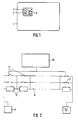
Fig. 1 zeigt einen Datenträger 1, wie er z. B. im bargeldlosen
Zahlungsverkehr als Buchungskarte oder als
Speicherkarte, wie z. B. als Telefonkarte, Anwendung
findet. Der Datenträger weist einen auf einem IC-Modul
2 befindlichen integrierten Schaltkreis (IC) auf, der über
die Kontaktflächen 3 mit externen Peripheriegeräten
elektrisch verbunden werden kann. Nach neuerem
Standard sind sechs Kontakte vorgesehen, wobei im allgemeinen
einer der Kontakte nicht belegt ist. Dieser
freie Anschluß des IC-Moduls, in den Fig. mit der Position
8 bezeichnet, wird als Meßanschluß zur externen
Messung einer physikalischen Eigenschaft des integrierten
Schaltkreises genutzt.Fig. 1 shows a
Fig. 2 zeigt das erfindungsgemäße separat auf dem
integrierten Schaltkreis zwischen dem Anschluß 8
(Meßanschluß) und dem Masseanschluß des Datenträgers
realisierte Netzwerk 9, bestehend aus den Widerständen
13. Die Widerstände besitzen von links nach
rechts binominal codierte Widerstandswerte, d. h. beginnend
mit dem ersten Widerstand z. B. 100 Ohm,
zweiter Widerstand 200 Ohm, dritter Widerstand 400
Ohm usw., und sind in Reihe geschaltet. Jedem Widerstand
der Widerstandsreihe ist jeweils eine Sicherung
12 und ein Schaltelement 11 parallel geschaltet. Die
Schaltelemente können z. B. per Software von einer
Steuerlogik 10 angesteuert werden, um die Sicherungen
entsprechend der gewünschten Codierung durchzubrennen.
Zum Durchbrennen der Sicherung wird ein
hoher Strom, z. B. 500 mA, an den Kontakt 8 gegen
Masse getrieben, wobei mit Hilfe der von der Steuerlogik
gesteuerten Schaltelemente nur die Sicherung
durchgebrannt wird, bei der der jeweilig dazu parallel
geschaltete Schalter geöffnet ist. Durch Ansteuerung
der Schalter kann die gewünschte Codierung, d. h. ein
eindeutig unterscheidbarer Gesamtwiderstandswert,
für die Widerstandsreihe erhalten werden. Bei der in Fig.
1 dargestellten Schalterstellung ist z. B. nur der erste
Schalter geöffnet und alle anderen sind geschlossen,
wodurch sich ein Gesamtwiderstandswert von 100 Ohm
für die zwischen dem Anschluß 8 und dem Masseanschluß
anliegende Widerstandsreihe ergibt. Die binominale
Codierung der Widerstandsreihe ermöglicht, daß
die Kombination der durchgebrannten Sicherungen einen
eindeutigen signifikanden Gesamtwiderstandswert
für die Widerstandsreihe ergibt, der als fortlaufende
Nummer digital darstellbar ist. Bei Kombination aller
möglichen Varianten ergibt sich somit eine fortlaufende
Nummer von i = 2n, wobei n der Anzahl der Widerstände
entspricht. Selbstverständlich kann anstelle einer binominal
codierten Widerstandsreihe auch eine andere geeignete
Codierung gewählt werden. Auch muß der Gesamtwiderstand
der Widerstandsreihe nicht für jeden integrierten
Schaltkreis individuell sein. Unter Umständen
kann es ausreichend sein, diesen klassen spezifisch zu
wählen, d. h. ein bestimmtes Fertigungslos von integrierten
Schaltkreisen kann mit ein und demselben Gesamtwiderstand
einer Widerstandsreihe codiert werden.
Nach dem Codieren der Widerstandsreihe, welches
im Testmodus, d. h. nachdem der Chip getestet
und für gut befunden wurde, stattfindet, kann die Verbindungsleitung
zwischen der Steuerlogik 10 und den
Schaltelementen 11 durch Zünden einer nicht dargestellten
Sicherung unterbrochen werden, um zu verhindern,
daß die Steuerlogik nachträglich von unbefugten
Dritten im Testmodus betrieben werden kann. Somit ist
die Steuerlogik nach dem Codierungsvorgang vom
Netzwerk entkoppelt, womit die physikalische Eigenschaft
des Netzwerkes irreversibel "eingebrannt" ist.
Dies bietet einen hohen Schutz gegenüber Manipulationen
seitens unbefugter Dritter.2 shows the
Im folgenden wird die Personalisierung von Datenträgern mit dem erfindungsgemäßen Netzwerk beschrieben. Zuerst wird die physikalische Eigenschaft des Netzwerkes gemessen und der gemessene Analogwert wird anschließend in einen Digitalwert umgesetzt. Anschließend wird der digitalisierte Meßwert mit Hilfe eines geheimen Schlüssels chiffriert. Dann erfolgt das Einschreiben der chiffrierten physikalischen Eigenschaft des Netzwerkes als Kenndatenwert in die Speichereinheit des Datenträgers. Selbstverständlich können auch andere sensitive Personalisierungsdaten, wie z. B. PIN, Transaktionslimit, mit der gemessenen physikalischen Eigenschaft des Netzwerkes in dem Personalisierungsgerät logisch verknüpft werden, um das Ergebnis der logischen Verknüpfung in eine Speichereinheit des Datenträgers zu schreiben. Als logische Verknüpfung kann z. B. eine EX-OR-Verknüpfung gewählt werden, die von dem Personalisierungsgerät ausgeführt wird.The following is the personalization of data carriers described with the network according to the invention. First is the physical property of the network and the measured analog value is then converted into a digital value. Then the digitized measured value is used Encrypted using a secret key. Then done the registration of the encrypted physical property of the network as a characteristic data value in the storage unit of the disk. Of course you can also other sensitive personalization data, such as e.g. B. PIN, transaction limit, with the measured physical Property of the network in the personalization device logically linked to the result the logical link in a storage unit to write the disk. As a logical link can e.g. B. selected an EX-OR link be executed by the personalization device becomes.
Fig. 3 zeigt in einem vereinfachten Blockschaltbild
ein Gerät 18 zur Echtheitsprüfung eines Datenträgers 1
mit dem erfindungsgemäßen Netzwerk 9. Der Datenträger
umfaßt neben dem Netzwerk 9 eine Logikeinheit 15,
eine Speichereinheit 16 und ein optional vorsehbares
Schaltelement 17, welches unter Steuerung der Logikeinheit
das Netzwerk für eine vorgegebene Zeitdauer in
den zwischen dem Meßkontakt 8 und dem Masseanschluß
durch die Meßeinrichtung 19 des Gerätes gebildeten
Meßpfad schaltet. Der Übersichtlichkeit wegen
wird die Meßeinrichtung 19 als Block dargestellt, der bereits
eine Spannungsversorgung z. B. von 10 V und einen
Analog-Digital-Wandler 23 zur Umsetzung des analogen
Meßwertsignales in einen digitalen Wert beinhaltet.
Die digitalisierte gemessene physikalische Eigenschaft
des Netzwerkes wird anschlie-ßend von dem
Chiffriermittel 20 unter Verwendung eines geheimen
Schlüssels, der in dem Chiffriermittel gegen äußeren
Zugriff gesichert gespeichert ist, verschlüsselt. Der von
der Leseeinrichtung 22 des Gerätes aus der Speichereinheit
16 des Datenträgers ausgelesene Kenndatenwert
wird mit dem vom Gerät verschlüsselten Meßergebnis
mit Hilfe eines Komparators 21 verglichen. Die
Speichereinheit 16 des Datenträgers kann beispielsweise
ein EEPROM sein, indem die physikalische Eigenschaft
des Netzwerkes in verschlüsselter Form abgespeichert
ist. Stimmt die von dem Gerät gemessene
physikalische Eigenschaft des Netzwerkes mit dem von
der Speichereinheit des Datenträgers ausgelesenen
Kenndatenwert überein, so wird der Datenträger als
echt erkannt.3 shows a simplified block diagram
a
Fig. 4 zeigt stark schematisiert den Ablauf zur Echtheitsprüfung
eines Datenträgers, der mit einem separaten
auf dem integrierten Schaltkreis befindlichen Netzwerk
versehen ist, dessen physikalische Eigenschaft
meßbar ist. Ist der Datenträger mit dem Prüfgerät über
die Kontaktelemente verbunden, so wird in dem Verfahrensschritt
30 vom Gerät zunächst geprüft, ob zwischen
dem Masseanschluß und dem Meßanschluß 8 die physikalische
Eigenschaft des Netzwerkes, z. B. in Form
des Gesamtwiderstandswertes einer Widerstandsreihe,
anliegt. Nur wenn das Gerät feststellt, daß der mit
der Meßeinrichtung gebildete Meßpfad aufgrund des
geöffneten Schaltelementes 17 nicht geschlossen, d. h.
hochohmig ist, wird von diesem im Verfahrensschritt 31
ein "Reset"-Signal zum Datenträger gesandt. Mit dem
Empfang des "Reset"-Signals wird der Adreßzähler der
Logikeinheit 15 in einen definierten Ausgangszustand
gesetzt und das Schaltelement geschlossen. Verfahrensschritt
32 zeigt, daß das Schaltelement 17 von der
Logikeinheit des Datenträgers per Software-Ansteuerung
bis zum Zeitpunkt des "Answer to Reset" (ATR) des
Datenträgers geschlossen ist und somit dis physikalische.
Eigenschaft des Netzwerkes innerhalb dieses
Zeitfensters für eine Messung durch die Meßeinrichtung
des Gerätes freigibt. Die Bestimmung der physikalischen
Eigenschaft des Netzwerkes, d. h. des Gesamtwiderstandswertes
der Widerstandsreihe und die anschließende
Verschlüsselung unter Verwendung eines
geheimen Schlüssels ist im Verfahrensschritt 33 dargestellt.
Im Verfahrensschritt 34 ist das Senden des in der
Speichereinheit des Datenträgers enthaltenen Kenndatenwertes
als drittes Byte im ATR, der vom Datenträger
zum Gerät geschickt wird, dargestellt. Verfahrensschritt
35 zeigt, wie der im dritten Byte des ATR empfangene
Kenndatenwert mit der aus dem Verfahrensschritt 33 erhaltenen
Meßgröße verglichen wird. Stimmen der von
dem Datenträger empfangene Kenndatenwert mit der
gemessenen digitalisierten und anschließend chiffrierten
physikalischen Eigenschaft des Netzwerkes überein,
so wird der Datenträger als echt erkannt. Das Ergebnis
der Echtheitsprüfung kann, wenn dies gewünscht
wird, auch auf einem Display des Gerätes angezeigt
werden.4 shows the sequence for the authenticity check in a highly schematic manner
of a disk with a separate
network located on the integrated circuit
is provided, its physical property
is measurable. Is the data carrier with the test device over
the contact elements connected, so in the process step
30 first checked by the device whether between
the ground connection and the
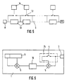
Fig. 5 zeigt ein weiteres Ausführungsbeispiel des
erfindungsgemäßen, auf dem integrierten Schaltkreis
separat vorhandenen Netzwerkes. Bei dieser Variante
existiert für jede Sicherung und jeden Widerstand ein
Testanschluß 14, auf den entsprechend der gewünschten
Codierung ein hoher Strom, z. B. 500 mA, zum
Durchbrennen der Sicherung gegeben wird, so daß die
Kombination der durchgebrannten Sicherungen einen
für die Widerstandsreihe charakteristischen Gesamtwiderstandswert
ergibt. Wie bereits bei der ersten Ausführungsform
sind die Sicherungen 12 zu den zwischen
dem Meßanschluß 8 und dem Masseanschluß in Reihe
geschalteten Widerständen 13 parallel geschaltet. Im
Vergleich zur ersten Ausführungsform kann bei dieser
Variante auf die Steuerlogik 10 und die Schalter 11 verzichtet
werden. Nach dem der Chip getestet und das
Netzwerk entsprechend codiert worden ist, werden die
Testanschlüsse 14 nach dem Codiervorgang abgeschaltet.
Dies kann dadurch erfolgen, daß die Testanschlüsse
einfach mechanisch abgetrennt werden. Da
bereits nach der Produktion und während des WaferTests
die Testkontakte zur Verfügung stehen, kann das
auf dem integrierten Schaltkreis separat vorgesehene
Netzwerk in einfacher Weise, beispielsweise in Form einer
Widerstandsreihe, realisiert werden.Fig. 5 shows a further embodiment of the
inventive, on the integrated circuit
separately existing network. In this variant
exists for every fuse and every
Die Fig. 6 zeigt in einer der Übersichtlichkeit wegen
stark schematisierten Darstellung einen Datenträger 1
mit intemen Einrichtungen 5 zur Überprüfung des elektrischen
Zustands einer Schaltung 24, die wenigstens
eine Sicherung 4, z. B. zum Schutz sensitiver Bereiche
des Datenträgers, aufweist. Nachdem der Chip getestet
und für gut befunden wurde und nachdem z. B. die gewünschte
Codierung des Echtheitsmerkmales des integrierten
Schaltkreises erfolgte, wird die Sicherung 4 gezündet,
wodurch sie von dem elektrisch leitenden in den
elektrisch nichtleitenden Zustand gebracht wird. Selbstverständlich
kann die Schaltung 24 auch noch weitere
Elemente zur Steuerung des Zündvorgangs aufweisen,
die jedoch dem Fachmann geläufig sind und der Einfachheit
halber hier nicht dargestellt werden. Zur Überprüfung
des elektrischen Zustands der Sicherung 4 wird
ein externes Signal, z. B. die Versorgungsspannung
oder das Taktsignal des integrierten Schaltkreises, über
eine mit dem Eingang der Sicherung elektrisch leitend
verbundene äußere Kontaktfläche 3 eingespeist und mit
dem am Ausgang der Sicherung empfangenen Signal
mittels eines ersten Komparators 5 verglichen. Das Vergleichsergebnis
des ersten Komparators wird als Kenndatenwert
z. B. nach jedem Anlegen des externen Signals
emeut in einen Speicher 16, z. b. RAM, geschrieben.
Das im RAM befindliche Vergleichsergebnis kann
im "Answer to Reset"-Signal (ATR) vom Datenträger zur
Echtheitsbestimmung an ein Kartenlesegerät übertragen
werden. Der RAM-Zustand kann bei jedem Betrieb
des Datenträgers mittels eines weiteren Komparators 5
mit einer Referenzinformation verglichen werden. Die
Referenzinformation stellt z. B. einen für den elektrisch
leitenden Zustand der Sicherung 4 repräsentativen
Wert dar und ist in einer gegen extemen Zugriff geschützten
nichtflüchtigen Speichereinheit 6 des Datenträgers
gespeichert. Bei Übereinstimmung mit der Referenzinformation,
d. h. wenn nach dem Zündvorgang
die Sicherung 4 einen nicht ordnungsgemäßen elektrisch
leitenden Zustand annimmt, wird von dem zweiten
Komparator 5 ein entsprechendes Sperrsignal erzeugt,
das genutzt werden kann, den Schaltkreis irreversibel
zu blockieren. Dazu wird beispielsweise in einen bestimmten
Bereich des gegen externen Zugriff geschützten
nichtflüchtigen Speichers 6 des integrierten Schaltkreises
eine die Sperre kennzeichnende Information
eingeschrieben. Bei jeder Initialisierung des Datenträgers
wird dieser bestimmte Speicherbereich vom integrierten
Schaltkreis abgefragt und bei Feststellung der
Sperrinformation wird z. B. die Steuereinheit des integrierten
Schaltkreises in den Haltezustand oder an den
Programmanfang zurückgesezt. In diesem Fall ergeht
eine Fehlermeldung, die jedoch keine Rückschlüsse zuläßt
auf die Tatsache, daß die Sicherung 4 den nicht ordnungsgemäßen,
d. h. elektrisch leitenden Zustand aufweist.
Die Fehlermeldung kann z. B. für einen außenstehenden
Dritten nicht erkennbar in dem zwischen
dem Datenträger und einem Gerät vereinbarten Datenaustauschprotokoll
mit erfolgen, z. B. bei einer Buchungskarte
im Echtheitssignal oder bei einer Speicherkarte
in der Meldung "Einheiten verbraucht".6 shows one for the sake of clarity
highly schematic representation of a
Claims (19)
- A system for testing the authenticity of a data carrier, comprisingcharacterized in thata data carrier (1) having at least one integrated circuit with memory units (6, 16) and logic units (15) as well as communication elements (3),an apparatus (18) having access via the communication elements (3) to at least partial areas of the memory units (6, 16) for reading and/or writing,means (5, 19) for determining a physical property of the integrated circuit,a separate circuit (9, 24) capable of assuming a plurality of more than four measurable electric states is located on the integrated circuit, the physical property consists of the irreversible adjustment of a significant electric state of the separate circuit (9, 24), and the adjusted significant state is used for forming a characteristic value designating the data carrier.
- The system of claim 1, characterized in that the circuit (9) includes at least one network consisting of passive components.
- The system of claim 2, characterized in that the measured physical property is the total resistance of a binomially coded resistor string.
- The system of claim 1, characterized in that the means (19) for measuring the physical property are part of the apparatus (18) which has encrypting means (20) for encoding the measured physical property of the circuit (9), the result of encoding being stored in memory means (16) of the data carrier (1) as a characteristic value.
- The system of claim 4, characterized in that the characteristic value is transferred from the data carrier (1) to the apparatus (18) as the third byte in the answer to reset (ATR).
- The system of claim 5, characterized in that the apparatus (18) has a comparator (21) for comparing the received characteristic value with the physical property of the circuit (9) measured and encoded by the apparatus (18), the comparison taking place at each operation of the data carrier (1).
- The system of claim 1, characterized in that the physical property of the circuit (9) is measurable only at a certain time for a predetermined duration.
- The system of claim 7, characterized in that time and duration are systemspecific parameters which are controlled by the logic unit (15) of the data carrier (1) in accordance with a signal received from the apparatus (18), and the apparatus (18) verifies whether these parameters fulfill predetermined conditions.
- The system of claim 8, characterized in that the signal transmitted from the apparatus (18) to the data carrier (1) is a reset signal, and the logic unit (15) releases the physical property of the circuit (9) for external measurement by means of a switching element (17) of the data carrier from the time of the received reset signal up to the time of the answer to reset (ATR) transmitted from the data carrier to the apparatus.
- The system of claim 1, characterized in that the circuit (24) has at least one fuse (4) which is brought by an ignition irreversibly from the electroconductive to the nonconductive state, thereby protecting sensitive areas of the data carrier (1) from external access.
- The system of claim 10, characterized in that the data carrier (1) has means (5) for checking the electric property of the fuse, whereby an external signal is fed in via a communication element (3) of the integrated circuit connected with the input of the fuse (4) and this is compared at the output of the fuse (4) with the fed-in signal and the result of comparison is written into a memory area (16) of the data carrier as a characteristic value.
- The system of claim 11, characterized in that the external signal is a signal absolutely necessary for operating the integrated circuit.
- The system of claim 11, characterized in that the characteristic value is contained in the answer to reset (ATR) of the data carrier and transferred to the apparatus (18) for authenticity testing at each operation of the data carrier (1).
- The system of claim 11, characterized in that the characteristic value is compared with internally stored reference information in the integrated circuit of the data carrier (1), and operation of the integrated circuit is blocked if an improper electric state of the fuse (4) has been ascertained.
- The system of claim 14, characterized in that upon blocked operation of the integrated circuit the data carrier (1) transfers an error message to the apparatus (18) which permits no conclusion to be drawn on the electric state of the fuse (4).
- A data carrier (1) having at least one integrated circuit with memory units (6, 16) and logic units (15) as well as communication elements (3), characterized in that a separate circuit (9, 24) having an adjustable and measurable physical property with a plurality of more than four possible electric states is located on the integrated circuit, the physical property being adjustable irreversibly to a significant electric state and said state being usable for forming a characteristic value designating the data carrier.
- The data carrier of claim 16, characterized in that the circuit (9) includes at least one network consisting of passive components.
- The data carrier of claim 16, characterized in that the circuit (24) has at least one fuse (4) which is brought by an ignition irreversibly from the electroconductive to the nonconductive state, thereby protecting sensitive areas of the data carrier (1) from external access.
- The data carrier of claim 18, characterized in that the data carrier (1) has means (5) for checking the electric property of the fuse.
Applications Claiming Priority (3)
| Application Number | Priority Date | Filing Date | Title |
|---|---|---|---|
| DE4243888A DE4243888A1 (en) | 1992-12-23 | 1992-12-23 | Data carrier and method for checking the authenticity of a data carrier |
| DE4243888 | 1992-12-23 | ||
| PCT/EP1993/003668 WO1994015318A1 (en) | 1992-12-23 | 1993-12-22 | System for checking the validity of a data carrier |
Publications (3)
| Publication Number | Publication Date |
|---|---|
| EP0676073A1 EP0676073A1 (en) | 1995-10-11 |
| EP0676073B1 EP0676073B1 (en) | 1996-11-13 |
| EP0676073B2 true EP0676073B2 (en) | 2000-01-19 |
Family
ID=6476429
Family Applications (1)
| Application Number | Title | Priority Date | Filing Date |
|---|---|---|---|
| EP94903866A Expired - Lifetime EP0676073B2 (en) | 1992-12-23 | 1993-12-22 | System for checking the validity of a data carrier |
Country Status (9)
| Country | Link |
|---|---|
| US (1) | US5917909A (en) |
| EP (1) | EP0676073B2 (en) |
| JP (1) | JPH08507164A (en) |
| AT (1) | ATE145294T1 (en) |
| DE (2) | DE4243888A1 (en) |
| ES (1) | ES2094046T5 (en) |
| HK (1) | HK1007816A1 (en) |
| SG (1) | SG50470A1 (en) |
| WO (1) | WO1994015318A1 (en) |
Cited By (2)
| Publication number | Priority date | Publication date | Assignee | Title |
|---|---|---|---|---|
| DE102004032707A1 (en) * | 2004-07-06 | 2006-02-02 | Infineon Technologies Ag | Disk with test mode |
| DE102005036303A1 (en) * | 2005-04-29 | 2007-08-16 | Giesecke & Devrient Gmbh | Method for initializing and / or personalizing a portable data carrier |
Families Citing this family (28)
| Publication number | Priority date | Publication date | Assignee | Title |
|---|---|---|---|---|
| US5644636A (en) * | 1994-12-30 | 1997-07-01 | Xtec, Incorporated | Method and apparatus for securing data stored in semiconductor memory cells |
| FR2738971B1 (en) * | 1995-09-19 | 1997-10-10 | Schlumberger Ind Sa | METHOD FOR DETERMINING AN ENCRYPTION KEY ASSOCIATED WITH AN INTEGRATED CIRCUIT |
| FR2738970B1 (en) * | 1995-09-19 | 1997-10-10 | Schlumberger Ind Sa | METHOD FOR DETERMINING A DIVERSIFIED KEY ASSOCIATED WITH AN INTEGRATED CIRCUIT |
| FR2745932A1 (en) * | 1996-03-11 | 1997-09-12 | Gemplus Card Int | Smart card with direct contact reading serving as ticket |
| AUPO799197A0 (en) * | 1997-07-15 | 1997-08-07 | Silverbrook Research Pty Ltd | Image processing method and apparatus (ART01) |
| AU7749998A (en) * | 1997-06-11 | 1998-12-30 | Nova-Technik Entwicklung Von Und Handel mit Medizinischen Ge raten GmbH | Document with an authentication feature |
| DE19734507C2 (en) | 1997-08-08 | 2000-04-27 | Siemens Ag | Method for checking the authenticity of a data carrier |
| US7587044B2 (en) * | 1998-01-02 | 2009-09-08 | Cryptography Research, Inc. | Differential power analysis method and apparatus |
| DE19822217B4 (en) * | 1998-05-18 | 2018-01-25 | Giesecke+Devrient Mobile Security Gmbh | Access-protected disk |
| WO2001052207A1 (en) * | 2000-01-11 | 2001-07-19 | Infineon Technologies Ag | Semiconductor chip with an unequivocal identity and method for establishing the unequivocal identity of a semiconductor chip |
| US6799274B1 (en) * | 2000-03-30 | 2004-09-28 | Western Digital Ventures, Inc. | Device comprising encryption circuitry enabled by comparing an operating spectral signature to an initial spectral signature |
| DE10018356B4 (en) * | 2000-04-13 | 2005-05-04 | Siemens Ag | Method for identifying an electronic control unit and suitable control unit |
| FR2823398B1 (en) * | 2001-04-04 | 2003-08-15 | St Microelectronics Sa | EXTRACTION OF PRIVATE DATA FOR AUTHENTICATION OF AN INTEGRATED CIRCUIT |
| FR2825873A1 (en) * | 2001-06-11 | 2002-12-13 | St Microelectronics Sa | PROTECTED STORAGE OF DATA IN AN INTEGRATED CIRCUIT |
| US7328339B1 (en) * | 2003-11-03 | 2008-02-05 | Advanced Micro Devices Inc | Method of testing the encryption function of a device |
| US8117452B2 (en) * | 2004-11-03 | 2012-02-14 | Cisco Technology, Inc. | System and method for establishing a secure association between a dedicated appliance and a computing platform |
| US8423788B2 (en) * | 2005-02-07 | 2013-04-16 | Sandisk Technologies Inc. | Secure memory card with life cycle phases |
| US8321686B2 (en) * | 2005-02-07 | 2012-11-27 | Sandisk Technologies Inc. | Secure memory card with life cycle phases |
| CN101164048B (en) * | 2005-02-07 | 2010-06-16 | 桑迪士克股份有限公司 | Safety system applied in memory card |
| US8108691B2 (en) * | 2005-02-07 | 2012-01-31 | Sandisk Technologies Inc. | Methods used in a secure memory card with life cycle phases |
| US7748031B2 (en) * | 2005-07-08 | 2010-06-29 | Sandisk Corporation | Mass storage device with automated credentials loading |
| US7536540B2 (en) * | 2005-09-14 | 2009-05-19 | Sandisk Corporation | Method of hardware driver integrity check of memory card controller firmware |
| US20070061597A1 (en) * | 2005-09-14 | 2007-03-15 | Micky Holtzman | Secure yet flexible system architecture for secure devices with flash mass storage memory |
| GB0615392D0 (en) * | 2006-08-03 | 2006-09-13 | Wivenhoe Technology Ltd | Pseudo random number circuitry |
| US20080072058A1 (en) * | 2006-08-24 | 2008-03-20 | Yoram Cedar | Methods in a reader for one time password generating device |
| US20080052524A1 (en) * | 2006-08-24 | 2008-02-28 | Yoram Cedar | Reader for one time password generating device |
| US8423794B2 (en) * | 2006-12-28 | 2013-04-16 | Sandisk Technologies Inc. | Method and apparatus for upgrading a memory card that has security mechanisms for preventing copying of secure content and applications |
| US8242831B2 (en) * | 2009-12-31 | 2012-08-14 | Intel Corporation | Tamper resistant fuse design |
Citations (1)
| Publication number | Priority date | Publication date | Assignee | Title |
|---|---|---|---|---|
| US4841133A (en) † | 1987-06-30 | 1989-06-20 | Motorola, Inc. | Data card circuits |
Family Cites Families (26)
| Publication number | Priority date | Publication date | Assignee | Title |
|---|---|---|---|---|
| IT1125188B (en) * | 1976-12-14 | 1986-05-14 | Selenia Ind Elettroniche | ENABLING AND COLLECTION FORM MADE BY ELECTRONIC CIRCUIT WITH COMPULSORY ELEMENTS FOR THE DISTRIBUTION OF GOODS OR SERVICES AND MACHINE OPERATING ON ITSELF |
| FR2401459A1 (en) * | 1977-08-26 | 1979-03-23 | Cii Honeywell Bull | PORTABLE INFORMATION MEDIA EQUIPPED WITH A MICROPROCESSOR AND A PROGRAMMABLE DEAD MEMORY |
| IT1207227B (en) * | 1979-08-09 | 1989-05-17 | Ates Componenti Elettron | REPRODUCIBLE. ELECTRONIC CARD WITH OBLITERABLE CELLS WITH KEY OF RECOGNITION NOT REPRODUCABLE FOR EQUIPMENT DISTRIBUTORS OF GOODS OR SERVICES AND METHOD FOR THE REALIZATION OF THAT KEY |
| FR2480539B1 (en) * | 1980-04-09 | 1985-09-13 | Cii Honeywell Bull | METHOD AND SYSTEM FOR TRANSMITTING SIGNED MESSAGES |
| JPS57167670A (en) * | 1981-04-07 | 1982-10-15 | Mitsubishi Electric Corp | Semiconductor device |
| US4926480A (en) * | 1983-08-22 | 1990-05-15 | David Chaum | Card-computer moderated systems |
| JPS60107852A (en) * | 1983-11-16 | 1985-06-13 | Toshiba Corp | Semiconductor integrated circuit |
| US4599489A (en) * | 1984-02-22 | 1986-07-08 | Gordian Systems, Inc. | Solid state key for controlling access to computer software |
| US4575621A (en) * | 1984-03-07 | 1986-03-11 | Corpra Research, Inc. | Portable electronic transaction device and system therefor |
| US4593384A (en) * | 1984-12-21 | 1986-06-03 | Ncr Corporation | Security device for the secure storage of sensitive data |
| JP2701836B2 (en) * | 1985-03-14 | 1998-01-21 | オムロン株式会社 | Circuit resistance value adjustment method |
| DE3526061A1 (en) * | 1985-07-20 | 1987-01-22 | Dhs Ges Fuer Elektromechanisch | Data acquisition apparatus |
| JPH0752261B2 (en) * | 1985-09-24 | 1995-06-05 | 株式会社日立マイコンシステム | Semiconductor integrated circuit device |
| GB2182176B (en) * | 1985-09-25 | 1989-09-20 | Ncr Co | Data security device for protecting stored data |
| JPS62137692A (en) * | 1985-12-11 | 1987-06-20 | Hitachi Ltd | Individual identification card |
| JPS62221053A (en) * | 1986-03-20 | 1987-09-29 | Fujitsu Ltd | Ic card system |
| JPS62251963A (en) * | 1986-04-25 | 1987-11-02 | Casio Comput Co Ltd | Certificating system for ic card |
| ES2051780T3 (en) * | 1987-03-04 | 1994-07-01 | Siemens Nixdorf Inf Syst | CIRCUIT PROVISION TO ENSURE ACCESS TO A DATA PROCESSING SYSTEM WITH THE HELP OF A CHIPS CARD. |
| CH673605A5 (en) * | 1987-10-01 | 1990-03-30 | Schlatter Ag | |
| DE3736882C2 (en) * | 1987-10-30 | 1997-04-30 | Gao Ges Automation Org | Method for checking the authenticity of a data carrier with an integrated circuit |
| FR2633420B1 (en) * | 1988-06-28 | 1992-02-21 | Schlumberger Ind Sa | INFORMATION MEDIUM AND SYSTEM FOR MANAGING SUCH MEDIA |
| US5239664A (en) * | 1988-12-20 | 1993-08-24 | Bull S.A. | Arrangement for protecting an electronic card and its use for protecting a terminal for reading magnetic and/or microprocessor cards |
| US5123045A (en) * | 1989-08-18 | 1992-06-16 | Massachusetts Institute Of Technology | Comprehensive software protection system |
| JP2524321Y2 (en) * | 1990-08-09 | 1997-01-29 | 日本信号株式会社 | IC card |
| US5146172A (en) * | 1990-08-15 | 1992-09-08 | Sundstrand Corp. | Engine identification system |
| JP2877547B2 (en) * | 1991-04-12 | 1999-03-31 | 株式会社東芝 | Portable storage media |
-
1992
- 1992-12-23 DE DE4243888A patent/DE4243888A1/en not_active Withdrawn
-
1993
- 1993-12-22 AT AT94903866T patent/ATE145294T1/en not_active IP Right Cessation
- 1993-12-22 WO PCT/EP1993/003668 patent/WO1994015318A1/en active IP Right Grant
- 1993-12-22 EP EP94903866A patent/EP0676073B2/en not_active Expired - Lifetime
- 1993-12-22 US US08/464,771 patent/US5917909A/en not_active Expired - Fee Related
- 1993-12-22 JP JP6514826A patent/JPH08507164A/en active Pending
- 1993-12-22 DE DE59304496T patent/DE59304496D1/en not_active Expired - Fee Related
- 1993-12-22 SG SG1996002211A patent/SG50470A1/en unknown
- 1993-12-22 ES ES94903866T patent/ES2094046T5/en not_active Expired - Lifetime
-
1998
- 1998-06-26 HK HK98106922A patent/HK1007816A1/en not_active IP Right Cessation
Patent Citations (1)
| Publication number | Priority date | Publication date | Assignee | Title |
|---|---|---|---|---|
| US4841133A (en) † | 1987-06-30 | 1989-06-20 | Motorola, Inc. | Data card circuits |
Cited By (5)
| Publication number | Priority date | Publication date | Assignee | Title |
|---|---|---|---|---|
| DE102004032707A1 (en) * | 2004-07-06 | 2006-02-02 | Infineon Technologies Ag | Disk with test mode |
| US7273182B2 (en) | 2004-07-06 | 2007-09-25 | Infineon Technologies Ag | Data storage medium having a test mode |
| DE102004032707B4 (en) * | 2004-07-06 | 2008-06-05 | Infineon Technologies Ag | Data carrier and method for testing a data carrier |
| DE102005036303A1 (en) * | 2005-04-29 | 2007-08-16 | Giesecke & Devrient Gmbh | Method for initializing and / or personalizing a portable data carrier |
| US7946499B2 (en) | 2005-04-29 | 2011-05-24 | Giesecke & Devrient Gmbh | Method for initializing and/or personalizng a portable data carrier |
Also Published As
| Publication number | Publication date |
|---|---|
| ATE145294T1 (en) | 1996-11-15 |
| DE4243888A1 (en) | 1994-06-30 |
| EP0676073A1 (en) | 1995-10-11 |
| SG50470A1 (en) | 1998-07-20 |
| EP0676073B1 (en) | 1996-11-13 |
| ES2094046T3 (en) | 1997-01-01 |
| HK1007816A1 (en) | 1999-04-23 |
| DE59304496D1 (en) | 1996-12-19 |
| WO1994015318A1 (en) | 1994-07-07 |
| JPH08507164A (en) | 1996-07-30 |
| ES2094046T5 (en) | 2000-06-01 |
| US5917909A (en) | 1999-06-29 |
Similar Documents
| Publication | Publication Date | Title |
|---|---|---|
| EP0676073B2 (en) | System for checking the validity of a data carrier | |
| EP0313967B1 (en) | Authentication method for a data carrier with integrated circuit | |
| DE3818960C2 (en) | ||
| EP0281057B1 (en) | Circuitry for securing the access to a data processor by means of an IC card | |
| DE19708616C2 (en) | Electronic data processing equipment and system | |
| DE3018945C2 (en) | Method and device for checking the admissibility of a connection between data transmission network participants | |
| DE69531556T2 (en) | METHOD AND DEVICE FOR SECURING DATA STORED IN SEMICONDUCTOR MEMORY CELLS | |
| EP0281058A2 (en) | Data exchange system | |
| DE2253275B2 (en) | Method and device for operating a communications transmission system protected against unauthorized access | |
| DE3041109A1 (en) | IDENTIFICATION ELEMENT | |
| DE3318101A1 (en) | CIRCUIT ARRANGEMENT WITH A STORAGE AND ACCESS CONTROL UNIT | |
| EP1188151A1 (en) | Devices and methods for biometric authentication | |
| EP0400441B1 (en) | Testing method for terminal communicating with IC-cards | |
| EP0712520B1 (en) | Process for verifying the authenticity of a data carrier | |
| EP1080454B1 (en) | Access-controlled data storage medium | |
| DE19527715A1 (en) | Smart card for access to global mobile communication system - has integrated circuit chip using identification and authentication data to control access | |
| EP0570924A2 (en) | Authentication method of one system-participant by another system-participant in an information transfer system composed of a terminal and of a portable data carrier | |
| DE102007041370B4 (en) | Chip card, electronic device, method for producing a chip card and method for using a chip card | |
| DE19938890C2 (en) | Integrated circuit and circuit arrangement for supplying power to an integrated circuit | |
| DE4405570C2 (en) | Electronic chip card access control system for common standard chip cards with electronic signature | |
| DE60223703T2 (en) | AUTHENTICATION PROTOCOL WITH MEMORY INTEGRITY VERIFICATION | |
| EP1722336A2 (en) | Data generating device and method for initialising security data carriers | |
| DE19850308B4 (en) | Method for protecting smart cards against misuse in third-party devices | |
| DE2735048C2 (en) | Process for the electronically controlled release of door, safe and function locks using electronically coded keys and a circuit arrangement for carrying out the process | |
| DE19818998B4 (en) | Method for protecting against attacks on the authentication algorithm or the secret key of a chip card |
Legal Events
| Date | Code | Title | Description |
|---|---|---|---|
| PUAI | Public reference made under article 153(3) epc to a published international application that has entered the european phase |
Free format text: ORIGINAL CODE: 0009012 |
|
| 17P | Request for examination filed |
Effective date: 19950620 |
|
| AK | Designated contracting states |
Kind code of ref document: A1 Designated state(s): AT BE CH DE DK ES FR GB GR IE IT LI LU MC NL PT SE |
|
| GRAG | Despatch of communication of intention to grant |
Free format text: ORIGINAL CODE: EPIDOS AGRA |
|
| 17Q | First examination report despatched |
Effective date: 19960112 |
|
| GRAH | Despatch of communication of intention to grant a patent |
Free format text: ORIGINAL CODE: EPIDOS IGRA |
|
| GRAH | Despatch of communication of intention to grant a patent |
Free format text: ORIGINAL CODE: EPIDOS IGRA |
|
| GRAA | (expected) grant |
Free format text: ORIGINAL CODE: 0009210 |
|
| AK | Designated contracting states |
Kind code of ref document: B1 Designated state(s): AT BE CH DE DK ES FR GB GR IE IT LI LU MC NL PT SE |
|
| PG25 | Lapsed in a contracting state [announced via postgrant information from national office to epo] |
Ref country code: NL Free format text: LAPSE BECAUSE OF FAILURE TO SUBMIT A TRANSLATION OF THE DESCRIPTION OR TO PAY THE FEE WITHIN THE PRESCRIBED TIME-LIMIT Effective date: 19961113 Ref country code: GR Free format text: LAPSE BECAUSE OF FAILURE TO SUBMIT A TRANSLATION OF THE DESCRIPTION OR TO PAY THE FEE WITHIN THE PRESCRIBED TIME-LIMIT Effective date: 19961113 Ref country code: DK Effective date: 19961113 |
|
| REF | Corresponds to: |
Ref document number: 145294 Country of ref document: AT Date of ref document: 19961115 Kind code of ref document: T |
|
| REF | Corresponds to: |
Ref document number: 59304496 Country of ref document: DE Date of ref document: 19961219 |
|
| REG | Reference to a national code |
Ref country code: IE Ref legal event code: FG4D Free format text: 70652 |
|
| PG25 | Lapsed in a contracting state [announced via postgrant information from national office to epo] |
Ref country code: LU Free format text: LAPSE BECAUSE OF NON-PAYMENT OF DUE FEES Effective date: 19961231 Ref country code: BE Effective date: 19961231 |
|
| REG | Reference to a national code |
Ref country code: ES Ref legal event code: FG2A Ref document number: 2094046 Country of ref document: ES Kind code of ref document: T3 |
|
| GBT | Gb: translation of ep patent filed (gb section 77(6)(a)/1977) |
Effective date: 19961202 |
|
| ITF | It: translation for a ep patent filed |
Owner name: STUDIO ING. ALFREDO RAIMONDI |
|
| PG25 | Lapsed in a contracting state [announced via postgrant information from national office to epo] |
Ref country code: PT Effective date: 19970213 |
|
| ET | Fr: translation filed | ||
| NLV1 | Nl: lapsed or annulled due to failure to fulfill the requirements of art. 29p and 29m of the patents act | ||
| PG25 | Lapsed in a contracting state [announced via postgrant information from national office to epo] |
Ref country code: IE Free format text: LAPSE BECAUSE OF NON-PAYMENT OF DUE FEES Effective date: 19970627 |
|
| PG25 | Lapsed in a contracting state [announced via postgrant information from national office to epo] |
Ref country code: MC Effective date: 19970630 |
|
| REG | Reference to a national code |
Ref country code: IE Ref legal event code: FD4D Ref document number: 70652 Country of ref document: IE |
|
| REG | Reference to a national code |
Ref country code: CH Ref legal event code: PL |
|
| PLBQ | Unpublished change to opponent data |
Free format text: ORIGINAL CODE: EPIDOS OPPO |
|
| PLBI | Opposition filed |
Free format text: ORIGINAL CODE: 0009260 |
|
| PLBF | Reply of patent proprietor to notice(s) of opposition |
Free format text: ORIGINAL CODE: EPIDOS OBSO |
|
| 26 | Opposition filed |
Opponent name: PHILIPS PATENTVERWALTUNG GMBH Effective date: 19970809 |
|
| REG | Reference to a national code |
Ref country code: CH Ref legal event code: AEN Free format text: DAS PATENT IST AUFGRUND DES WEITERBEHANDLUNGSANTRAG VOM 26.09.1997 REAKTIVIERT WORDEN. |
|
| PLBF | Reply of patent proprietor to notice(s) of opposition |
Free format text: ORIGINAL CODE: EPIDOS OBSO |
|
| PLAW | Interlocutory decision in opposition |
Free format text: ORIGINAL CODE: EPIDOS IDOP |
|
| PLAW | Interlocutory decision in opposition |
Free format text: ORIGINAL CODE: EPIDOS IDOP |
|
| PUAH | Patent maintained in amended form |
Free format text: ORIGINAL CODE: 0009272 |
|
| STAA | Information on the status of an ep patent application or granted ep patent |
Free format text: STATUS: PATENT MAINTAINED AS AMENDED |
|
| 27A | Patent maintained in amended form |
Effective date: 20000119 |
|
| AK | Designated contracting states |
Kind code of ref document: B2 Designated state(s): AT BE CH DE DK ES FR GB GR IE IT LI LU MC NL PT SE |
|
| REG | Reference to a national code |
Ref country code: CH Ref legal event code: AEN Free format text: AUFRECHTERHALTUNG DES PATENTES IN GEAENDERTER FORM |
|
| GBTA | Gb: translation of amended ep patent filed (gb section 77(6)(b)/1977) |
Effective date: 20000209 |
|
| ITF | It: translation for a ep patent filed |
Owner name: STUDIO ING. ALFREDO RAIMONDI |
|
| ET3 | Fr: translation filed ** decision concerning opposition | ||
| REG | Reference to a national code |
Ref country code: ES Ref legal event code: DC2A Kind code of ref document: T5 Effective date: 20000413 |
|
| REG | Reference to a national code |
Ref country code: GB Ref legal event code: IF02 |
|
| PGFP | Annual fee paid to national office [announced via postgrant information from national office to epo] |
Ref country code: GB Payment date: 20041207 Year of fee payment: 12 |
|
| PGFP | Annual fee paid to national office [announced via postgrant information from national office to epo] |
Ref country code: AT Payment date: 20041227 Year of fee payment: 12 |
|
| PGFP | Annual fee paid to national office [announced via postgrant information from national office to epo] |
Ref country code: SE Payment date: 20041228 Year of fee payment: 12 Ref country code: ES Payment date: 20041228 Year of fee payment: 12 |
|
| PGFP | Annual fee paid to national office [announced via postgrant information from national office to epo] |
Ref country code: CH Payment date: 20041229 Year of fee payment: 12 |
|
| PG25 | Lapsed in a contracting state [announced via postgrant information from national office to epo] |
Ref country code: IT Free format text: LAPSE BECAUSE OF NON-PAYMENT OF DUE FEES;WARNING: LAPSES OF ITALIAN PATENTS WITH EFFECTIVE DATE BEFORE 2007 MAY HAVE OCCURRED AT ANY TIME BEFORE 2007. THE CORRECT EFFECTIVE DATE MAY BE DIFFERENT FROM THE ONE RECORDED. Effective date: 20051222 Ref country code: GB Free format text: LAPSE BECAUSE OF NON-PAYMENT OF DUE FEES Effective date: 20051222 Ref country code: AT Free format text: LAPSE BECAUSE OF NON-PAYMENT OF DUE FEES Effective date: 20051222 |
|
| PG25 | Lapsed in a contracting state [announced via postgrant information from national office to epo] |
Ref country code: SE Free format text: LAPSE BECAUSE OF NON-PAYMENT OF DUE FEES Effective date: 20051223 Ref country code: ES Free format text: LAPSE BECAUSE OF NON-PAYMENT OF DUE FEES Effective date: 20051223 |
|
| PG25 | Lapsed in a contracting state [announced via postgrant information from national office to epo] |
Ref country code: LI Free format text: LAPSE BECAUSE OF NON-PAYMENT OF DUE FEES Effective date: 20051231 Ref country code: CH Free format text: LAPSE BECAUSE OF NON-PAYMENT OF DUE FEES Effective date: 20051231 |
|
| REG | Reference to a national code |
Ref country code: CH Ref legal event code: PL |
|
| EUG | Se: european patent has lapsed | ||
| GBPC | Gb: european patent ceased through non-payment of renewal fee |
Effective date: 20051222 |
|
| PGFP | Annual fee paid to national office [announced via postgrant information from national office to epo] |
Ref country code: FR Payment date: 20061215 Year of fee payment: 14 |
|
| PGFP | Annual fee paid to national office [announced via postgrant information from national office to epo] |
Ref country code: DE Payment date: 20070221 Year of fee payment: 14 |
|
| REG | Reference to a national code |
Ref country code: ES Ref legal event code: FD2A Effective date: 20051223 |
|
| PG25 | Lapsed in a contracting state [announced via postgrant information from national office to epo] |
Ref country code: DE Free format text: LAPSE BECAUSE OF NON-PAYMENT OF DUE FEES Effective date: 20080701 |
|
| REG | Reference to a national code |
Ref country code: FR Ref legal event code: ST Effective date: 20081020 |
|
| PG25 | Lapsed in a contracting state [announced via postgrant information from national office to epo] |
Ref country code: FR Free format text: LAPSE BECAUSE OF NON-PAYMENT OF DUE FEES Effective date: 20071231 |