EP0671742B1 - Signalization of types of defects of an optical information carrier - Google Patents
Signalization of types of defects of an optical information carrier Download PDFInfo
- Publication number
- EP0671742B1 EP0671742B1 EP95103711A EP95103711A EP0671742B1 EP 0671742 B1 EP0671742 B1 EP 0671742B1 EP 95103711 A EP95103711 A EP 95103711A EP 95103711 A EP95103711 A EP 95103711A EP 0671742 B1 EP0671742 B1 EP 0671742B1
- Authority
- EP
- European Patent Office
- Prior art keywords
- error
- cause
- occurrence
- bursts
- frames
- Prior art date
- Legal status (The legal status is an assumption and is not a legal conclusion. Google has not performed a legal analysis and makes no representation as to the accuracy of the status listed.)
- Expired - Lifetime
Links
- 230000003287 optical effect Effects 0.000 title claims description 33
- 230000007547 defect Effects 0.000 title claims description 3
- 238000000034 method Methods 0.000 claims description 24
- 238000012545 processing Methods 0.000 claims description 15
- 230000011664 signaling Effects 0.000 claims description 15
- 230000002950 deficient Effects 0.000 claims description 6
- 241001484259 Lacuna Species 0.000 claims 1
- 239000000969 carrier Substances 0.000 description 7
- 238000012937 correction Methods 0.000 description 5
- 238000001514 detection method Methods 0.000 description 2
- 238000010586 diagram Methods 0.000 description 2
- 238000004519 manufacturing process Methods 0.000 description 2
- 238000012360 testing method Methods 0.000 description 2
- 230000002159 abnormal effect Effects 0.000 description 1
- 238000004364 calculation method Methods 0.000 description 1
- 238000011109 contamination Methods 0.000 description 1
- 230000007423 decrease Effects 0.000 description 1
- 238000013461 design Methods 0.000 description 1
- 238000005516 engineering process Methods 0.000 description 1
- 230000007613 environmental effect Effects 0.000 description 1
- 238000011156 evaluation Methods 0.000 description 1
- 235000015244 frankfurter Nutrition 0.000 description 1
- 238000007689 inspection Methods 0.000 description 1
- 239000011241 protective layer Substances 0.000 description 1
- 238000003908 quality control method Methods 0.000 description 1
- 238000005070 sampling Methods 0.000 description 1
- 230000005236 sound signal Effects 0.000 description 1
- 230000001360 synchronised effect Effects 0.000 description 1
- 230000000007 visual effect Effects 0.000 description 1
Images

Classifications
-
- G—PHYSICS
- G11—INFORMATION STORAGE
- G11B—INFORMATION STORAGE BASED ON RELATIVE MOVEMENT BETWEEN RECORD CARRIER AND TRANSDUCER
- G11B7/00—Recording or reproducing by optical means, e.g. recording using a thermal beam of optical radiation by modifying optical properties or the physical structure, reproducing using an optical beam at lower power by sensing optical properties; Record carriers therefor
- G11B7/08—Disposition or mounting of heads or light sources relatively to record carriers
- G11B7/09—Disposition or mounting of heads or light sources relatively to record carriers with provision for moving the light beam or focus plane for the purpose of maintaining alignment of the light beam relative to the record carrier during transducing operation, e.g. to compensate for surface irregularities of the latter or for track following
- G11B7/0948—Disposition or mounting of heads or light sources relatively to record carriers with provision for moving the light beam or focus plane for the purpose of maintaining alignment of the light beam relative to the record carrier during transducing operation, e.g. to compensate for surface irregularities of the latter or for track following specially adapted for detection and avoidance or compensation of imperfections on the carrier, e.g. dust, scratches, dropouts
-
- G—PHYSICS
- G11—INFORMATION STORAGE
- G11B—INFORMATION STORAGE BASED ON RELATIVE MOVEMENT BETWEEN RECORD CARRIER AND TRANSDUCER
- G11B27/00—Editing; Indexing; Addressing; Timing or synchronising; Monitoring; Measuring tape travel
- G11B27/36—Monitoring, i.e. supervising the progress of recording or reproducing
-
- G—PHYSICS
- G11—INFORMATION STORAGE
- G11B—INFORMATION STORAGE BASED ON RELATIVE MOVEMENT BETWEEN RECORD CARRIER AND TRANSDUCER
- G11B20/00—Signal processing not specific to the method of recording or reproducing; Circuits therefor
- G11B20/10—Digital recording or reproducing
- G11B20/18—Error detection or correction; Testing, e.g. of drop-outs
- G11B20/1816—Testing
-
- G—PHYSICS
- G11—INFORMATION STORAGE
- G11B—INFORMATION STORAGE BASED ON RELATIVE MOVEMENT BETWEEN RECORD CARRIER AND TRANSDUCER
- G11B27/00—Editing; Indexing; Addressing; Timing or synchronising; Monitoring; Measuring tape travel
- G11B27/10—Indexing; Addressing; Timing or synchronising; Measuring tape travel
- G11B27/34—Indicating arrangements
-
- G—PHYSICS
- G11—INFORMATION STORAGE
- G11B—INFORMATION STORAGE BASED ON RELATIVE MOVEMENT BETWEEN RECORD CARRIER AND TRANSDUCER
- G11B33/00—Constructional parts, details or accessories not provided for in the other groups of this subclass
- G11B33/10—Indicating arrangements; Warning arrangements
-
- G—PHYSICS
- G11—INFORMATION STORAGE
- G11B—INFORMATION STORAGE BASED ON RELATIVE MOVEMENT BETWEEN RECORD CARRIER AND TRANSDUCER
- G11B2220/00—Record carriers by type
- G11B2220/20—Disc-shaped record carriers
-
- G—PHYSICS
- G11—INFORMATION STORAGE
- G11B—INFORMATION STORAGE BASED ON RELATIVE MOVEMENT BETWEEN RECORD CARRIER AND TRANSDUCER
- G11B2220/00—Record carriers by type
- G11B2220/20—Disc-shaped record carriers
- G11B2220/25—Disc-shaped record carriers characterised in that the disc is based on a specific recording technology
- G11B2220/2537—Optical discs
- G11B2220/2545—CDs
-
- G—PHYSICS
- G11—INFORMATION STORAGE
- G11B—INFORMATION STORAGE BASED ON RELATIVE MOVEMENT BETWEEN RECORD CARRIER AND TRANSDUCER
- G11B2220/00—Record carriers by type
- G11B2220/20—Disc-shaped record carriers
- G11B2220/25—Disc-shaped record carriers characterised in that the disc is based on a specific recording technology
- G11B2220/2537—Optical discs
- G11B2220/2587—Laser Discs; Optical disc using analog recording
Definitions
- the invention relates to a method and an arrangement for Error type signaling of optical information carriers with one Playback device in the sense of a "fuzzy logic" that not only that Presence of an error, but the nature of the error, such as for example fingerprints on a compact disc and thereby, where appropriate, enables the consumer to: original reproduction quality of the optical Restore information carrier.
- the area to which the The invention relates to at least signaling a type of error in optical information carriers, as in negligent handling of the compact disc (CD), laser disc or Similar information carriers occur, which is usually player intended to reproduce the information is used.
- optical information carriers In spite of the greatest care point to the recording and reproduction of audio and / or video signals or data signals optical information carriers both manufacturing and environmental errors, to some extent with a Error correction device corrected by the playback devices or interpolated.
- the Compact would be without this ability Disc or laser disc not realizable, because then none of the many bits are lost or none of the countless Pits in the disc may be smeared or covered.
- errors in the optical information carrier can at least influence or lead to the originality of the reproduction Playback failures. Both accidental occur Individual errors, such as air bubbles or contamination in the Protective layer of the optical information carrier, as well so-called surface defects, i.e. scratches and fingerprints, that destroy or hide a lot of information, so that the consumer can no longer distinguish whether original or calculated or interpolated information are reproduced.
- the error correction is a reflection of the degree of error of the optical information carrier that the in the player existing program counter signals.
- the degree of error represents both the frequency and the number of Error.
- a method for error detection in the case of signals stored on disc-shaped, rotating information carriers in spiral tracks in which an error signal is identified by comparison with the signal contained in previous revolutions in such a way that a scratch and without a repetition of the error signal in the next revolution Repetition of an individual error is registered, cf. DE-OS 28 51 822.
- a shift register with the length of one revolution is provided for carrying out the method. Spatially limited errors are found electronically in some specific way and are given as a pulse signal to the input of the device.
- the method is based on comparing an error signal with the signal content of previous revolutions. A repetition of the error signal in the radial direction at the same location in the next revolution is registered with a shift register.
- US-A-4,287,587 shows a detector for a video disc playback system which checks a signal received from the video disc to determine whether its amplitude decreases with increasing playing time. A statement about the type of error of the video disc error is not possible.
- EP-A-73 519 an optical turntable is known which has an error correction device for the data read from the information carrier and emits a signal corresponding to the number of corrected bit words. If it is no longer possible to correct the bit words, it is indicated that the record carrier should be changed or at least cleaned. It is not possible to distinguish whether it is a fingerprint disorder or an area error.
- the invention is therefore based on the object of a method and to create an arrangement that with little effort Signaling at least one type of error of an optical Record carrier, such as fingerprints, with enables a playback device so that the consumer with the Advice or signaling system to assess the Quality of the optical recording medium facilitated and a Note on achieving a better playback quality with the The cause of the fingerprint is given.
- the object is achieved in that in a first step, at least one cause of error or type of error and determined in a second Process step is signaled or displayed.
- the optical information carrier just played a Has errors explicitly causes at least one error displayed so that the consumer in the event of the cause of the fault Fingerprint by simply wiping the fingerprints, preferably straight from the center to the edge can restore the original playback quality.
- the starting point of the process is the optical information carrier, which in particular through multiple and negligent Handling increasingly has errors and with a more common play device used to reproduce the information is optically scanned.
- Degree of error represents the degree of error of an optical disk Number of bad frames that the decoder does not more corrected, related to the location of the error, where the error location from the number of subcode blocks between error packets assessed according to the error rate can be.
- the cause of the error is identified with a error rate occurring in adjacent tracks of a disk sector certainly.
- the repairable cause of the error is preferably found in the imprint Occurrence of more than three error packets in five neighboring ones Tracks displayed.
- scratches and so-called Black dots preferably when up to three occur Error packets identified in three adjacent tracks or determined and signaled as the cause of the error.
- the consumer is signaled that whether it's light fingerprints, strong fingerprints or one audible through fingerprints or another The cause of the error is disturbed playback.
- the fault representative signal preferably with a disk circulation equivalent signal linked. This avoids that several short glitches that are not from fingerprints result in a fingerprint corresponding to the signal Add signal.
- the signal equivalent to disk circulation is preferably the output signal of the so-called Radial detector. Furthermore, it is advantageous in the process of Summation of a specified number of track completions to detect the radial expansion of fingerprints not already cancel if under the count single track circulation is free of interference signals.
- the display of one or more error causes takes place visually and / or acoustically. To ensure that the If the operator perceives the error display, the cause of the error becomes also beyond the period of their occurrence signals.
- An arrangement for carrying out the method, which from a processing circuit for processing errors signals representing an optical information carrier of the player and for feeding to a display device for at least one cause of error.
- a processing circuit that processing the degree of error signals representing an optical information carrier serves is preferably on the decoder or program error counter of the player and connected by a faulty Frames in relation to the arithmetic logic unit educated.
- Regardless of the structure of the processing circuit with which at least one cause of error is identified is visual and / or acoustically signaling display device provided that one or more light emitting diodes, one Display or display fields or one or more sound signals generating ringer. With the display device are preferably repairable causes of errors or repairable and / or irreparable causes of errors are also displayed.
- the display device and the processing circuit to an error indicator put together which as a separate error display device with the Player is connected or the error indicator is in the Integrated player and forms a structural with this Unit.
- the advantages of the method and the arrangement are in particular in that the operator of the player judging the reproduction quality of an optical information carrier is facilitated, existing in the player Facilities and process steps already implemented are used can become and the consumer explicit information about possible causes of errors of the currently playing optical information carrier that receives it in the case of fingerprints, by simple means Wipe the original playback quality of the optical Restore information carrier.
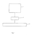
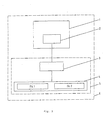
- 1 corresponds to the method for fault type signaling optical information carrier with a playback device 1, with at least one cause of error in the first procedural step determined and displayed in the second step with a processing circuit 3 and a display device 4 performed.
- the first step in the process is that of the degree of error that a decoder 2 not shown in FIG. 1 the player 1 provides at least one cause of error is determined.
- the degree of error of an optical recording medium is shown in FIG. 2 accordingly with the start of the player PLAY first Number of errors related to the occurrence investigating tracks k and an error rate z representative flag m set to zero. Even the number of Subcode blocks y become the same at the start of the PLAY device Set to zero. With the appearance of the first Subcode synchronous signal SCOR is advanced in the signal flow.
- the flag m representing the error rate z becomes set when interpolation occurs for the first time
- the number of Subcode blocks y per revolution x result from the scanning diameter, which is calculated from the so-called subcode ATIME is multiplied by the number divided by the product from subcode block time and scanning speed.
- the Sampling speed is known for each disk only once and determine the number of subcode blocks y each Revolution x is preferably rounded off as an integer.
- the flag m representing the error rate z becomes the same Set one and then increase the number of Subcode blocks y waited for one, whether in the same disk sector an error rate z occurs again.
- the flag m representing the error rate z becomes the same Set one and then increase the number of Subcode blocks y waited for one, whether in the same disk sector an error rate z occurs again.
- the inaccuracy of two subcode blocks y considered. This is followed by an incorrect evaluation Frames in error packets h. Accordingly more experimental Results was one on four frames within a 96 frame corresponding subcode block time related size of the error packets h chosen to be used in combination with a Occurrence of errors to be examined number of tracks k a distinction between the causes of error fingerprint and scratches to allow black dot.
- the fault representative signal with a disk circulation equivalent signal linked. This avoids that several short glitches that are not from fingerprints result, add to a signal corresponding to a fingerprint.
- a disk equivalent signal it is preferred the output signal of the so-called radial detector used.
- it is advantageous to the process of Summation of a specified number of track completions corresponding to the plate revolutions for detecting the radial Expansion of fingerprints does not already abort if as part of the count a single track circulation free of Interference signals.
- FIG. 3 An arrangement corresponding to this embodiment is shown in FIG. 3 shown. It consists of the player 1, the one Degree of error of the decoder signaling the optical disk 2 contains, a processing circuit 3 and one Display device 4. At the decoder 2 is the processing circuit 3 connected with the the degree of error of the straight played optical disc signals are processed. It is a computing unit with which defective Frames are placed in relation to the fault location. in the The result of the calculation will be one of the available ones Failure causes fingerprint or scratch, black dot determined and a related signal to that on the processing circuit 3 connected display device 4, the corresponding cause of the error on the display as the first type of error FA1 or the second type of error FA2 signals.
- a processing circuit 3 and a display device 4 can corresponding to Figure 3 with the player 1 to a structural unit 6 can be summarized.
Landscapes
- Engineering & Computer Science (AREA)
- Signal Processing (AREA)
- Optical Recording Or Reproduction (AREA)
- Signal Processing For Digital Recording And Reproducing (AREA)
Description
Die Erfindung betrifft ein Verfahren und eine Anordnung zur Fehlerartsignalisation optischer Informationsträger mit einem Wiedergabegerät im Sinne einer "Fuzzy Logic", die nicht nur das Vorhandensein eines Fehlers, sondern die Art des Fehlers, wie zum Beispiel Fingerabdrücke auf einer Compact Disc, signalisiert und es dadurch dem Verbraucher gegebenenfalls ermöglicht, die ursprüngliche Wiedergabequalität des optischen Informationsträgers wiederherzustellen. Das Gebiet, dem die Erfindung zuzuordnen ist, betrifft das Signalisieren mindestens einer Fehlerart optischer Informationsträger, wie sie bei fahrlässigem Umgang mit der Compact Disc (CD), Laserdisc oder ähnlichen Informationsträgern auftreten, wobei das üblicherweise zur Wiedergabe der Information vorgesehene Abspielgerät verwendet wird.The invention relates to a method and an arrangement for Error type signaling of optical information carriers with one Playback device in the sense of a "fuzzy logic" that not only that Presence of an error, but the nature of the error, such as for example fingerprints on a compact disc and thereby, where appropriate, enables the consumer to: original reproduction quality of the optical Restore information carrier. The area to which the The invention relates to at least signaling a type of error in optical information carriers, as in negligent handling of the compact disc (CD), laser disc or Similar information carriers occur, which is usually player intended to reproduce the information is used.
Trotz größter Sorgfalt weisen zur Aufzeichnung und Wiedergabe von Audio- und/oder Videosignalen oder Datensignalen verwendete optische Informationsträger sowohl herstellungs- als auch umweltbedingte Fehler auf, die in gewissem Umfang mit einer Fehlerkorrektureinrichtung von den Abspielgeräten korrigiert bzw. interpoliert werden. Ohne diese Fähigkeit wären die Compact Disc oder Laserdisc nicht realisierbar, da dann keines der vielen Bits verlorengehen beziehungsweise keiner der unzähligen Pits in der Scheibe verschmiert oder verdeckt werden dürfte. Fehler des optischen Informationsträgers können jedoch zumindest die Originalität der Wiedergabe beeinflussen oder führen zu Ausfällen bei der Wiedergabe. Es treten sowohl zufällige Einzelfehler, wie Luftbläschen oder Verschmutzungen in der Schutzschicht des optischen Informationsträgers, als auch sogenannte Flächenfehler, also Kratzer und Fingerabdrücke auf, die sehr viele Informationen zerstören oder verdecken, so daß der Verbraucher nicht mehr unterscheiden kann, ob ursprüngliche oder berechnete beziehungsweise interpolierte Informationen wiedergegeben werden. In spite of the greatest care point to the recording and reproduction of audio and / or video signals or data signals optical information carriers both manufacturing and environmental errors, to some extent with a Error correction device corrected by the playback devices or interpolated. The Compact would be without this ability Disc or laser disc not realizable, because then none of the many bits are lost or none of the countless Pits in the disc may be smeared or covered. However, errors in the optical information carrier can at least influence or lead to the originality of the reproduction Playback failures. Both accidental occur Individual errors, such as air bubbles or contamination in the Protective layer of the optical information carrier, as well so-called surface defects, i.e. scratches and fingerprints, that destroy or hide a lot of information, so that the consumer can no longer distinguish whether original or calculated or interpolated information are reproduced.
Zur Anzeige der technischen Qualität einer gerade gespielten CD ist ein Fehleranzeigegerät bekannt, das die Auslastung der Fehlerkorrektur anzeigt, vgl. KRIEG, Bernhard: Praxis der digitalen Audiotechnik: digitale Aufnahme und Wiedergabe, Franzis-Verlag GmbH, München 1989, S. 60 - 63. Die Auslastung der Fehlerkorrektur ist ein Spiegelbild des Fehlergrades des optischen Informationsträgers, den der im Abspielgerät vorhandene Program-Counter signalisiert. Der Fehlergrad repräsentiert sowohl die Häufigkeit als auch die Anzahl der Fehler. Obwohl er ein direktes Indiz für die technische Qualität einer gerade gespielten CD ist, erhält der Verbraucher keinen Aufschluß über gegebenenfalls notwendige Maßnahmen zum Verringern des Fehlergrades, da zwar die Häufigkeit und Anzahl der Fehler, jedoch nicht die Art des Fehlers signalisiert wird. Die Fehlerartsignalisierung erfordert somit ein in der Komplexität über den Fehlergrad hinausgehendes System. Es ist allgemein bekannt, derartige Systeme die den Menschen als Entscheidungsträger gewichteter komplexer Probleme unterstützen, als "Fuzzy Logic" zu bezeichnen.To display the technical quality of a CD being played is known an error display device that the load of the Displays error correction, cf. KRIEG, Bernhard: Practice of digital audio technology: digital recording and playback, Franzis-Verlag GmbH, Munich 1989, pp. 60 - 63. The load The error correction is a reflection of the degree of error of the optical information carrier that the in the player existing program counter signals. The degree of error represents both the frequency and the number of Error. Although it is a direct indication of the technical quality of a CD that has just been played, the consumer does not receive any Information about any necessary measures for Reduce the degree of error because of the frequency and number the error is signaled, but not the type of error. The type of error signaling therefore requires complexity System going beyond the level of error. It is generally known, such systems which humans as Support decision-makers of weighted complex problems, to be called "fuzzy logic".
Es ist weiterhin bekannt, daß bei der CD-Herstellung
Laser-Scanner zur optischen Inspektion der Informationsträger
verwendet werden, die einen hohen Aufwand erfordern und mit denen
im Rahmen einer Gütekontrolle mit einem automatischen
Prüfsystem eine Gut/Schlecht-Sortierung der CDs erfolgt, vgl.
,,Wenn es klickt, nicht gleich den Spieler schelten", in:
Frankfurter Allgemeine Zeitung vom 07.01.1992. Als Prüfkriterium
dient ebenfalls der Fehlergrad, der die Anzahl der
Störereignisse auf der Platte repräsentiert. Ein derartig
aufwendiges System zur Fehlersignalisierung des optischen
Informationsträgers in Form eines Zusatzgerätes ist dem Verbraucher
jedoch nicht zuzumuten. Es sei erwähnt, daß mit diesen
Einrichtungen auch keine Unterscheidung zwischen den unterschiedlichen
Fehlerarten erfolgen kann. It is also known that laser scanners are used for the optical inspection of the information carriers in CD production, which require a high outlay and with which a good / bad sorting of the CDs takes place within the scope of a quality control with an automatic test system, cf. "If it clicks, do not immediately scold the player", in:
Frankfurter Allgemeine Zeitung of January 7, 1992. The degree of error, which represents the number of disturbance events on the disk, also serves as a test criterion. Such a complex system for error signaling of the optical information carrier in the form of an additional device is unacceptable to the consumer. It should be mentioned that these devices cannot differentiate between the different types of errors.
Weiterhin ist ein Verfahren zur Fehlerermittlung bei auf scheibenförmigen,
rotierenden Informationsträgern in Spiralspuren gespeicherten Signalen
bekannt, bei dem ein Fehlersignal durch Vergleich mit dem Signal inhalt
vorgehender Umdrehungen in der Weise identifiziert wird, daß bei einer
Wiederholung des Fehlersignals in der nächstfolgenden Umdrehungen eine
Schramme und ohne Wiederholung ein Einzelfehler registriert wird, vgl. DE-OS
28 51 822. Zur Durchführung des Verfahrens ist ein Schieberegister von
der Länge einer Umdrehung vorgesehen. Räumlich begrenzte Fehler werden
auf irgendeine spezifische Weise elektronisch gefunden und als Impulssignal
an den Eingang der Einrichtung gegeben. Das Verfahren beruht darauf, daß
ein Fehlersignal mit dem Signalinhalt vorhergehender Umdrehungen
verglichen wird. Es wird eine Wiederholung des Fehlersignals in radialer
Richtung am gleichen Ort in der nächsten Umdrehung mit einem
Schieberegister registriert. Dadurch führen nur Fehler bzw. Fehlersignale, die
auf einer gradlinig radial verlaufenden Linie des Aufzeichnungsträgers
auftreten, zum Signalisieren einer Schramme. Die Tatsache, daß Schrammen
oder Kratzer jedoch einen Verlauf aufweisen, der in aller Regel nicht mit einer
geradlinig radial verlaufenden Linie übereinstimmt, wird nicht berücksichtigt.
Das elektronische Fehlersignal wird in ein Schieberegister mit einer Länge
von exakt einem Umlauf eingeschrieben, so daß nur auf einer geraden
Radiallinie befindliche Orte erfaßt werden.
Zur Ortsbestimmung wird ein bei Abspielgeräten für scheibenförmige,
rotierende Informationsträger unüblicher, starr an der Antriebsachse des
Informationsträgers angebrachter Impulsgeber verwendet.
Aus der GB-A-2 137 799 ist ein Schmutzerkennungs- und Anzeigesystem für
Informationsauslesesysteme bekannt. Hierbei wird eine abnormale
Bedingung des Auslesesignals detektiert und angezeigt. Allerdings kann
auch mit diesem bekannten System nur allgemein auf das Vorhandensein
eines Fehlers hingewiesen werden; eine Aussage über die Fehlerart ist nicht
möglich.
Die US-A-4,287,587 zeigt einen Detektor für ein Videodisk-Abspielsystem,
welcher ein von der Videodisk erhaltenes Signal dahingehend prüft, ob
dessen Amplitude mit zunehmender Spielzeit abnimmt. Eine Aussage über
die Fehlerart des Fehlers der Videodisk ist nicht möglich.
Gemäß EP-A-73 519 ist ein optischer Plattenspieler bekannt, der eine
Fehlerkorrektureinrichtung für die vom Informationsträger gelesenen Daten
aufweist und ein der Anzahl korrigierter Bitwörter entsprechendes Signal
abgibt. Sofern eine Korrektur der Bitwörter nicht mehr möglich ist wird
angezeigt, daß der Aufzeichnungsträger gewechselt oder wenigstens
gesäubert werden sollte. Eine Unterscheidung, ob es sich um eine Störung
durch Fingerabdrücke oder einen Flächenfehler handelt, ist nicht möglich. Furthermore, a method for error detection in the case of signals stored on disc-shaped, rotating information carriers in spiral tracks is known, in which an error signal is identified by comparison with the signal contained in previous revolutions in such a way that a scratch and without a repetition of the error signal in the next revolution Repetition of an individual error is registered, cf. DE-OS 28 51 822. A shift register with the length of one revolution is provided for carrying out the method. Spatially limited errors are found electronically in some specific way and are given as a pulse signal to the input of the device. The method is based on comparing an error signal with the signal content of previous revolutions. A repetition of the error signal in the radial direction at the same location in the next revolution is registered with a shift register. As a result, only errors or error signals that occur on a straight radial line of the recording medium lead to the signaling of a scratch. However, the fact that scratches or scratches have a course that generally does not match a straight radial line is not taken into account. The electronic error signal is written into a shift register with a length of exactly one revolution, so that only locations located on a straight radial line are detected.
A pulse generator, which is unusual in playback devices for disc-shaped, rotating information carriers and is rigidly attached to the drive axis of the information carrier, is used for determining the location.
From GB-A-2 137 799 a dirt detection and display system for information reading systems is known. Here, an abnormal condition of the readout signal is detected and displayed. However, even with this known system, the presence of an error can only be indicated in general; a statement about the type of error is not possible.
US-A-4,287,587 shows a detector for a video disc playback system which checks a signal received from the video disc to determine whether its amplitude decreases with increasing playing time. A statement about the type of error of the video disc error is not possible.
According to EP-A-73 519 an optical turntable is known which has an error correction device for the data read from the information carrier and emits a signal corresponding to the number of corrected bit words. If it is no longer possible to correct the bit words, it is indicated that the record carrier should be changed or at least cleaned. It is not possible to distinguish whether it is a fingerprint disorder or an area error.
Der Erfindung liegt deshalb die Aufgabe zugrunde, ein Verfahren und eine Anordnung zu schaffen, die mit geringem Aufwand das Signalisieren mindestens einer Fehlerart eines optischen Aufzeichnungsträgers, wie beispielsweise Fingerabdrücke, mit einem Wiedergabegerät ermöglicht, so daß dem Verbraucher mit dem Beratungs- beziehungsweise Signalisiersystem das Beurteilen der Qualität des optischen Aufzeichnungsträgers erleichtert und ein Hinweis zum Erreichen einer besseren Wiedergabequalität beim Vorliegen der Fehlerursache Fingerabdruck gegeben wird.The invention is therefore based on the object of a method and to create an arrangement that with little effort Signaling at least one type of error of an optical Record carrier, such as fingerprints, with enables a playback device so that the consumer with the Advice or signaling system to assess the Quality of the optical recording medium facilitated and a Note on achieving a better playback quality with the The cause of the fingerprint is given.
Die gestellte Aufgabe wird erfindungsgemäß dadurch gelöst, daß in einem ersten Verfahrensschritt mindestens eine Fehlerursache beziehungsweise Fehlerart ermittelt und in einem zweiten Verfahrensschritt signalisiert beziehungsweise angezeigt wird.The object is achieved in that in a first step, at least one cause of error or type of error and determined in a second Process step is signaled or displayed.
Sofern der gerade abgespielte optische Informationsträger einen Fehler aufweist, wird explizit mindestens eine Fehlerursache angezeigt, so daß der Verbraucher im Fall der Fehlerursache Fingerabdruck durch einfaches Abwischen der Fingerabdrücke, vorzugsweise geradlinig von der Mitte zum Rand, die ursprüngliche Wiedergabequalität wieder herstellen kann.If the optical information carrier just played a Has errors, explicitly causes at least one error displayed so that the consumer in the event of the cause of the fault Fingerprint by simply wiping the fingerprints, preferably straight from the center to the edge can restore the original playback quality.
Ausgangspunkt des Verfahrens bildet der optische Informationsträger, der insbesondere durch mehrfache und fahrlässige Handhabung zunehmend Fehler aufweist und mit einem üblicher weise zur Wiedergabe der Informationen verwendeten Abspielgerät optisch abgetastet wird.The starting point of the process is the optical information carrier, which in particular through multiple and negligent Handling increasingly has errors and with a more common play device used to reproduce the information is optically scanned.
Aufgrund der örtlichen Charakteristik, die die Fehlerursachen aufweisen, wird zum Ermitteln der Fehlerursache aus dem Fehlergrad eine den Fehlergrad einer optischen Platte repräsentierende Anzahl fehlerhafter Frames, die vom Decoder nicht mehr korrigiert wird, in Beziehung zum Fehlerort gesetzt, wobei der Fehlerort aus der Anzahl der Subcodeblöcke zwischen entsprechend der Fehlerrate bewerteten Fehlerpaketen ermittelt werden kann. Die Fehlerursache wird dadurch mit einer in benachbarten Spuren eines Plattensektors auftretenden Fehlerrate bestimmt.Because of the local characteristics that cause the failure have to determine the cause of the error from the Degree of error represents the degree of error of an optical disk Number of bad frames that the decoder does not more corrected, related to the location of the error, where the error location from the number of subcode blocks between error packets assessed according to the error rate can be. The cause of the error is identified with a error rate occurring in adjacent tracks of a disk sector certainly.
Vorzugsweise wird die reparable Fehlerursache Finderabdruck beim Auftreten von mehr als drei Fehlerpaketen in fünf benachbarten Spuren angezeigt. Andererseits werden Kratzer und sogenannte Black- Dots vorzugsweise beim Auftreten von bis zu drei Fehlerpaketen in drei benachbarten Spuren identifiziert beziehungsweise als Fehlerursache ermittelt und signalisiert.The repairable cause of the error is preferably found in the imprint Occurrence of more than three error packets in five neighboring ones Tracks displayed. On the other hand, scratches and so-called Black dots preferably when up to three occur Error packets identified in three adjacent tracks or determined and signaled as the cause of the error.
Darüber hinaus ist es sowohl mit der vom Fehlergrad als auch mit einer vom Hochfrequenzsignal ausgehenden Lösung durch Variieren der Parameter und gegebenenfalls Kombination der Lösungen möglich, unterschiedliche Fehlerursachen zu ermittelt und eine Wichtung des Grades der Fehlerursache oder Fehlerursachen vorzunehmen. Dem Verbraucher wird beispielsweise signalisiert, ob es sich um leichte Fingerabdrücke, starke Fingerabdrücke oder um eine hörbar durch Fingerabdrücke oder eine andere Fehlerursache gestörte Wiedergabe handelt.In addition, it is both with the degree of error and with a solution based on the radio frequency signal by varying the parameters and, if necessary, a combination of the solutions possible to determine different causes of errors and one Weighting the degree of cause or cause of error to make. For example, the consumer is signaled that whether it's light fingerprints, strong fingerprints or one audible through fingerprints or another The cause of the error is disturbed playback.
Um den Grad der Sicherheit der Identifikation von Fingerabdrücken gegenüber anderen Störungen zu erhöhen, wird das Fehler repräsentierende Signal vorzugsweise mit einem dem Plattenumlauf äquivalenten Signal verknüpft. Dadurch wird vermieden, daß sich mehrere kurze Störungen, die nicht von Fingerabdrücken herrühren, zu einem dem Signal Fingerabdruck entsprechenden Signal addieren. Das dem Plattenumlauf äquivalente Signal ist vorzugsweise das Ausgangssignal des sogenannten Radial-Detektors. Weiterhin ist es vorteilhaft den Vorgang der Summierung einer festgelegten Anzahl von Track-Absolvierungen zum Detektieren der radialen Ausdehnung von Fingerabdrücken nicht bereits abzubrechen, wenn im Rahmen der Zählung ein einzelner Track-Umlauf frei von Störsignalen ist.To the degree of security of fingerprint identification to increase over other disturbances, the fault representative signal preferably with a disk circulation equivalent signal linked. This avoids that several short glitches that are not from fingerprints result in a fingerprint corresponding to the signal Add signal. The signal equivalent to disk circulation is preferably the output signal of the so-called Radial detector. Furthermore, it is advantageous in the process of Summation of a specified number of track completions to detect the radial expansion of fingerprints not already cancel if under the count single track circulation is free of interference signals.
Das Anzeigen einer Fehlerursache oder mehrerer Fehlerursachen erfolgt visuell und/oder akustisch. Um zu gewährleisten, daß der Bedienende die Fehleranzeige wahrnimmt, wird die Fehlerursache auch über den Zeitraum ihres Auftretens hinausgehend signalisiert.The display of one or more error causes takes place visually and / or acoustically. To ensure that the If the operator perceives the error display, the cause of the error becomes also beyond the period of their occurrence signals.
Zur Durchführung des Verfahrens ist eine Anordnung vorgesehen, die aus einer Verarbeitungsschaltung zur Verarbeitung Fehler eines optischen Informationsträgers repräsentierender Signale des Abspielgerätes und zur Zuführung zu einer Anzeigevorrichtung für mindestens eine Fehlerursache besteht.An arrangement is provided for carrying out the method, which from a processing circuit for processing errors signals representing an optical information carrier of the player and for feeding to a display device for at least one cause of error.
Eine Verarbeitungsschaltung, die der Verarbeitung den Fehlergrad eines optischen Informationsträgers repräsentierender Signale dient, wird vorzugsweise am Decoder bzw. Program-Error-Counter des Abspielgerätes angeschlossen und von einer fehlerhafte Frames in Beziehung zum Fehlerort setzenden Recheneinheit gebildet.A processing circuit that processing the degree of error signals representing an optical information carrier serves, is preferably on the decoder or program error counter of the player and connected by a faulty Frames in relation to the arithmetic logic unit educated.
Unabhängig vom Aufbau der Verarbeitungsschaltung, mit der mindestens eine Fehlerursache ermittelt wird, ist eine visuell und/oder akustisch signalisierende Anzeigevorrichtung vorgesehen, die aus einer oder mehreren Leuchtdioden, einem Display oder Anzeigefeldern oder einer ein oder mehrere Tonsignale erzeugenden Tonrufeinrichtung besteht. Mit der Anzeigevorrichtung werden vorzugsweise reparable Fehlerursachen oder auch reparable und/oder irreparable Fehlerursachen angezeigt.Regardless of the structure of the processing circuit with which at least one cause of error is identified is visual and / or acoustically signaling display device provided that one or more light emitting diodes, one Display or display fields or one or more sound signals generating ringer. With the display device are preferably repairable causes of errors or repairable and / or irreparable causes of errors are also displayed.
Hinsichtlich der Gerätegestaltung werden die Anzeigevorrichtung und die Verarbeitungsschaltung zu einem Fehleranzeigegerät zusammengefügt, welches als separates Fehleranzeigegerät mit dem Abspielgerät verbunden ist oder das Fehleranzeigegerät ist im Abspielgerät integriert und bildet mit diesem eine bauliche Einheit. With regard to the device design, the display device and the processing circuit to an error indicator put together, which as a separate error display device with the Player is connected or the error indicator is in the Integrated player and forms a structural with this Unit.
Die Vorteile des Verfahrens und der Anordnung bestehen insbesondere darin, daß dem Betreiber des Abspielgerätes das Beurteilen der Wiedergabequalität eines optischen Informationsträgers erleichtert wird, hierzu im Abspielgerät vorhandene Einrichtungen und bereits realisierte Verfahrensschritte verwendet werden können und der Verbraucher eine explizite Information über gegebenenfalls vorhandene Fehlerursachen des gerade abgespielten optischen Informationsträgers erhält, die es ihm im Fall von Fingerabdrücken ermöglicht, durch einfaches Abwischen die ursprüngliche Wiedergabequalität des optischen Informationsträgers wieder herzustellen.The advantages of the method and the arrangement are in particular in that the operator of the player judging the reproduction quality of an optical information carrier is facilitated, existing in the player Facilities and process steps already implemented are used can become and the consumer explicit information about possible causes of errors of the currently playing optical information carrier that receives it in the case of fingerprints, by simple means Wipe the original playback quality of the optical Restore information carrier.
Das Verfahren und die Anordnung sind mit geringem Aufwand realisierbar und der Verbraucher erhält Aufschlüsse darüber, ob ursprüngliche oder wesentlich mit einem Korrektursystem berechnete beziehungsweise interpolierte Informationen wiedergegeben werden.The procedure and the arrangement are with little effort feasible and the consumer receives information about whether original or essentially with a correction system calculated or interpolated information reproduced become.
Das Verfahren und die Anordnung sind in den Ansprüche 1 und 5 definiert.The method and the arrangement are defined in
Im folgenden wird die Erfindung anhand einen Ausführungsweg darstellenden Zeichnungen näher erläutert.In the following the invention is based on an embodiment illustrative drawings explained in more detail.
Es zeigen
- Fig. 1
- ein Blockschaltbild zur Durchführung des
Verfahrens zur Fehlerartsignalisation optischer
Informationsträger mit einemAbspielgerät 1, - Fig. 2
- ein Flußdiagramm zum vom Fehlergrad ausgehenden Verfahren der Fehlerartanzeige,
- Fig. 3
- ein Blockschaltbild einer Anordnung zur vom Fehlergrad ausgehenden Fehlerartanzeige.
- Fig. 1
- a block diagram for performing the method for error type signaling optical
Information carrier with aplayback device 1, - Fig. 2
- a flowchart for the method of displaying the type of error based on the degree of error,
- Fig. 3
- a block diagram of an arrangement for the type of error based on the degree of error.
Fig. 1 entsprechend wird das Verfahren zur Fehlerartsignalisation
optischer Informationsträger mit einem Abspielgerät 1,
mit dem im ersten Verfahrensschritt mindestens eine Fehlerursache
ermittelt und im zweiten Verfahrensschritt angezeigt
wird, mit einer Verarbeitungsschaltung 3 und einer Anzeigevorrichtung
4 durchgeführt.1 corresponds to the method for fault type signaling
optical information carrier with a
In einem ersten Ausführungsweg zur Fehlerartsignalisation einer
Compact Disc besteht der erste Verfahrensschritt darin, daß aus
dem Fehlergrad, den ein in Fig. 1 nicht dargestellter Decoder 2
des Abspielgerätes 1 bereitstellt, mindestens eine Fehlerursache
ermittelt wird. Zum Ermitteln von Fehlerursachen aus dem
Fehlergrad eines optischen Aufzeichnungsträgers werden Fig. 2
entsprechend mit dem Start des Abspielgerätes PLAY zunächst die
Anzahl der hinsichtlich des Auftretens von Fehlern zu
untersuchenden Spuren k sowie ein eine Fehlerrate z
darstellendes Flag m Null gesetzt. Auch die Zahl der
Subcodeblöcke y wird beim Start des Abspielgerätes PLAY gleich
Null gesetzt. Mit dem Auftreten des ersten
Subcode-Synchronsignals SCOR wird im Signalflußverlauf weitergeschaltet.
Das die Fehlerrate z darstellende Flag m wird
gesetzt, wenn erstmalig eine Interpolation auftritt, deren
Vorliegen analog zur Fehlerrate z von den, den Fehlergrad der
optischen Platte signalisierenden Einrichtungen des Abspielgerätes
abgeleitet wird. Tritt eine Fehlerrate z = 1 auf,
wird durch Berechnung der Zahl der Subcodeblöcke y je Umdrehung
x eine Ortsbestimmung OB durchgeführt. Die Zahl der
Subcodeblöcke y je Umdrehung x ergibt sich aus dem Abtastdurchmesser,
der aus dem sogenannten Subcode ATIME berechnet
wird, multipliziert mit der Zahl, dividiert durch das Produkt
aus Subcodeblockzeit und Abtastgeschwindigkeit. Die
Abtastgeschwindigkeit ist in bekannter Weise für jede Platte nur
einmal zu bestimmen und die Zahl der Subcodeblöcke y je
Umdrehung x wird vorzugsweise als ganze Zahl abgerundet.
Weiterhin wird das die Fehlerrate z darstellende Flag m gleich
Eins gesetzt und anschließend durch Erhöhen der Zahl der
Subcodeblöcke y um Eins abgewartet, ob im gleichen Plattensektor
erneut eine Fehlerrate z auftritt. Außerdem wird in einem
folgenden Schritt die Ungenauigkeit von zwei Subcodeblöcken y
berücksichtigt. Dem schließt sich eine Bewertung fehlerhafter
Frames in Fehlerpaketen h an. Entsprechend experimenteller
Ergebnisse wurde eine auf vier Frames innerhalb einer 96 Frames
entsprechenden Subcodeblockzeit bezogene Größe der Fehlerpakete
h gewählt, um in Kombination mit einer hinsichtlich des
Auftretens von Fehlern zu untersuchenden Anzahl von Spuren k
eine Unterscheidung zwischen den Fehlerursachen Fingerabdruck
und Kratzer, Black-Dot zu ermöglichen. Es hat sich gezeigt, daß
die reparable Fehlerursache Fingerabdruck als erste Fehlerart
FA1 beim Auftreten von mehr als drei Fehlerpaketen h in fünf
benachbarten Spuren k vorliegt. Andererseits werden Kratzer und
Black-Dots als zweite Fehlerart FA2 beim Auftreten von bis zu
drei Fehlerpaketen h in drei benachbarten Spuren k
identifiziert.In a first embodiment for fault type signaling of a
Compact Disc The first step in the process is that of
the degree of error that a
Um den Grad der Sicherheit der Identifikation von Fingerabdrücken gegenüber anderen Störungen zu erhöhen, wird das Fehler repräsentierende Signal mit einem dem Plattenumlauf äquaivalenten Signal verknüpft. Dadurch wird vermieden, daß sich mehrere kurze Störungen, die nicht von Fingerabdrücken herrühren, zu einem Fingerabdruck entsprechenden Signal addieren. Als einem Plattenumlauf äquivalentes Signal wird vorzugsweise das Ausgangssignal des sogenannten Radial-Detektors verwendet. Anderseits ist es vorteilhaft, den Vorgang der Summierung einer festgelegten Anzahl von Track-Absolvierungen entsprechend der Plattenumläufe zum Detektieren der radialen Ausdehnung von Fingerabdrücken nicht bereits abzubrechen, wenn im Rahmen der Zählung ein einzelner Track-Umlauf frei von Störsignalen ist.To the degree of security of fingerprint identification to increase over other disturbances, the fault representative signal with a disk circulation equivalent signal linked. This avoids that several short glitches that are not from fingerprints result, add to a signal corresponding to a fingerprint. As a disk equivalent signal, it is preferred the output signal of the so-called radial detector used. On the other hand, it is advantageous to the process of Summation of a specified number of track completions corresponding to the plate revolutions for detecting the radial Expansion of fingerprints does not already abort if as part of the count a single track circulation free of Interference signals.
Eine diesem Ausführungsweg entsprechende Anordnung ist in Fig. 3
dargestellt. Sie besteht aus dem Abspielgerät 1, das einen den
Fehlergrad der optischen Platte signalisierenden Decoder 2
enthält, einer Verarbeitungsschaltung 3 und einer
Anzeigevorrichtung 4. Am Decoder 2 ist die Verarbeitungsschaltung
3 angeschlossen, mit der die den Fehlergrad der gerade
gespielten optischen Platte repräsentierenden Signale
verarbeitet werden. Sie ist eine Recheneinheit, mit der fehlerhafte
Frames im Beziehung zum Fehlerort gesetzt werden. Im
Ergebnis der Berechnung wird eine der gegebenenfalls vorliegenden
Fehlerursachen Fingerabdruck oder Kratzer, Black-Dot
ermittelt und ein diesbezügliches Signal zu der an der Verarbeitungsschaltung
3 angeschlossenen Anzeigevorrichtung 4 weitergeleitet,
die die entsprechende Fehlerursache mittels Display
als erste Fehlerart FA1 beziehungsweise zweite Fehlerart FA2
signalisiert.An arrangement corresponding to this embodiment is shown in FIG. 3
shown. It consists of the
Unabhängig vom Ausführungsweg des ersten Verfahrensschrittes
wird dann mit der bereits erwähnten Anzeigevorrichtung 4 in
einem zweiten Verfahrensschritt mindestens eine Fehlerursache
signalisiert.Regardless of the route of execution of the first process step
is then in with the
Eine Verarbeitungsschaltung 3 und eine Anzeigevorrichtung 4
können Figur 3 entsprechend mit dem Abspielgerät 1 zu einer
baulichen Einheit 6 zusammengefaßt sein.A
Claims (6)
- Method for signalling at least one cause of error on optically scanned information media or, respectively, optical disks, such as fingerprints and/or pits for example, in a playback device (1) which is used for reproducing information from an optical information medium, by comparison with an error rate (z) occurring in neighbouring tracks (k) of a disk sector of a compact disk and having predetermined limit values where, when an error burst (h) first occurs, which is formed on the occurrence of an error rate (z) from a plurality of defective frames within a subcode block time (y) corresponding to a multiplicity of frames, a comparison takes place as to whether error bursts (h) also occur in the area of the location of the occurrence of first error bursts (h) after at least one revolution and, when more than a predetermined number, corresponding to a plurality, of error bursts (h) occur in a predetermined number, corresponding to a plurality, of neighbouring tracks (k), at least the cause of error "fingerprint" is determined and signalled.
- Method according to Claim 1, characterized in that the number of the subcode blocks (y) is determined from the scanning diameter, which is calculated from the subcode (ATIME), multiplied by the number π, divided by the product of the subcode block time and scanning rate.
- Method according to Claim 1, characterized in that an error burst (h) is formed on the occurrence of an error rate (z) of four defective frames within a subcode block time (y) corresponding to 96 frames and a comparison takes place as to whether error bursts (h) also occur in the area of the location of the occurrence of first error bursts (h) after at least one revolution and, when more than three error bursts (h) occur in five neighbouring tracks (k), the cause of error "fingerprint" is determined.
- Method according to one of Claims 1 to 3, characterized in that at least one cause of error is signalled visually and/or acoustically beyond the immediate duration of its occurrence until an optical disk or a magazine of optical disks is inserted again.
- Arrangement for signalling at least one cause of error of optically scanned information media or optical disks, such as fingerprints and/or pits for example, by comparison of the locations of the occurrence of an error signal, having in a playback device (1) which is used for reproducing information a processing circuit (3) for processing signals, which represent errors, from an optical information medium and for feeding to a display device (4) for at least one cause of error "fingerprint", the processing circuit (3) being a computing unit which is connected to a decoder (2) of the playback device (1) and relates defective frames to a defect location which is calculated from subcode blocks (y), by means of which computing unit at least one cause of error "fingerprint" is determined from an error rate (z) occurring in neighbouring tracks (k) of a disk sector by comparison with predetermined limit values of a compact disk, in that, when an error burst (h) first occurs which is formed on the occurrence of an error rate (z) from a plurality of defective frames within a subcode block time (y) corresponding to a multiplicity of frames, a comparison takes place as to whether error bursts (h) also occur in the area of the location of the occurrence of first error bursts (h) after at least one revolution and, when more than a predetermined number, corresponding to a plurality, of error bursts (h) occur in a predetermined number, corresponding to a plurality, of neighbouring tracks (k), at least the cause of error "fingerprint" is determined and the processing circuit (3) is connected to the display device (4).
- Arrangement according to Claim 5, characterized in that, using the computing unit, an error burst (h) is formed when an error rate (z) of four defective frames occurs within a subcode block time (y) corresponding to 96 frames, and a comparison takes place as to whether error bursts (h) also [lacuna], after at least one revolution, in the area of the location of the occurrence of first error bursts (h) in five neighbouring tracks (k), the cause of error "fingerprint" is determined [sic].
Applications Claiming Priority (7)
| Application Number | Priority Date | Filing Date | Title |
|---|---|---|---|
| DE4118672 | 1991-06-07 | ||
| DE4118672 | 1991-06-07 | ||
| DE4120870 | 1991-06-25 | ||
| DE4120870 | 1991-06-25 | ||
| DE4210264 | 1992-03-28 | ||
| DE4210264 | 1992-03-28 | ||
| EP92910751A EP0587615B1 (en) | 1991-06-07 | 1992-05-28 | Signalization of types of defects of an optical information carrier |
Related Parent Applications (2)
| Application Number | Title | Priority Date | Filing Date |
|---|---|---|---|
| EP92910751.4 Division | 1992-05-28 | ||
| EP92910751A Division EP0587615B1 (en) | 1991-06-07 | 1992-05-28 | Signalization of types of defects of an optical information carrier |
Publications (2)
| Publication Number | Publication Date |
|---|---|
| EP0671742A1 EP0671742A1 (en) | 1995-09-13 |
| EP0671742B1 true EP0671742B1 (en) | 2000-01-12 |
Family
ID=27202565
Family Applications (3)
| Application Number | Title | Priority Date | Filing Date |
|---|---|---|---|
| EP95103711A Expired - Lifetime EP0671742B1 (en) | 1991-06-07 | 1992-05-28 | Signalization of types of defects of an optical information carrier |
| EP92910751A Expired - Lifetime EP0587615B1 (en) | 1991-06-07 | 1992-05-28 | Signalization of types of defects of an optical information carrier |
| EP92108998A Pending EP0517099A1 (en) | 1991-06-07 | 1992-05-28 | Error motive signalling of optical information carriers |
Family Applications After (2)
| Application Number | Title | Priority Date | Filing Date |
|---|---|---|---|
| EP92910751A Expired - Lifetime EP0587615B1 (en) | 1991-06-07 | 1992-05-28 | Signalization of types of defects of an optical information carrier |
| EP92108998A Pending EP0517099A1 (en) | 1991-06-07 | 1992-05-28 | Error motive signalling of optical information carriers |
Country Status (12)
| Country | Link |
|---|---|
| EP (3) | EP0671742B1 (en) |
| JP (2) | JP3270044B2 (en) |
| KR (1) | KR100282089B1 (en) |
| CN (1) | CN1040376C (en) |
| DE (2) | DE59208917D1 (en) |
| ES (2) | ES2109357T3 (en) |
| HK (1) | HK1011112A1 (en) |
| MY (1) | MY108595A (en) |
| PT (1) | PT671742E (en) |
| SG (1) | SG48113A1 (en) |
| TW (1) | TW207581B (en) |
| WO (1) | WO1992022064A1 (en) |
Families Citing this family (6)
| Publication number | Priority date | Publication date | Assignee | Title |
|---|---|---|---|---|
| US6266791B1 (en) * | 1999-02-05 | 2001-07-24 | Hewlett-Packard Company | System and method for selectively recovering areas on a disc marked as unuseable |
| WO2001052249A1 (en) * | 2000-01-13 | 2001-07-19 | Matsushita Electric Industrial Co., Ltd. | Optical disk recording/reproducing apparatus |
| JP3785972B2 (en) * | 2001-09-06 | 2006-06-14 | ティアック株式会社 | Signal processing circuit |
| KR100964686B1 (en) * | 2003-11-14 | 2010-06-21 | 엘지전자 주식회사 | Method for testing Anti-Contamination of Disk Surface |
| ITMI20040985A1 (en) * | 2004-05-17 | 2004-08-17 | Technicolor S P A | AUTOMATIC SOUND SYNCHRONIZATION DETECTION |
| US7969844B2 (en) * | 2006-07-10 | 2011-06-28 | Panasonic Corporation | Optical disc device |
Family Cites Families (15)
| Publication number | Priority date | Publication date | Assignee | Title |
|---|---|---|---|---|
| US287587A (en) * | 1883-10-30 | beainebd spoonee | ||
| DE2851822C2 (en) * | 1978-11-30 | 1986-01-16 | Polygram Gmbh, 2000 Hamburg | Method for error assessment in the case of signals stored in spiral tracks on rotating information carriers and circuit arrangement for carrying out the method |
| US4287587A (en) * | 1980-03-07 | 1981-09-01 | Rca Corporation | Signal loss dectector for video disc |
| JPS5837847A (en) * | 1981-08-31 | 1983-03-05 | Sony Corp | Optical disk reproducer |
| JPS59142756A (en) * | 1983-02-04 | 1984-08-16 | Sony Corp | Optical disk reproducing device |
| JPH0643901Y2 (en) * | 1983-03-15 | 1994-11-14 | パイオニア株式会社 | Optical information reader with dirt detection display function |
| DE3341628A1 (en) * | 1983-11-17 | 1985-05-30 | Polygram Gmbh, 2000 Hamburg | DEVICE ARRANGEMENT FOR DETECTING ERRORS IN DISK-SHAPED INFORMATION CARRIERS |
| JPS60127574A (en) * | 1983-12-14 | 1985-07-08 | Toshiba Corp | Drop-out detecting circuit |
| JPS61242347A (en) * | 1985-04-19 | 1986-10-28 | Toshiba Corp | Optical disk reproducing device |
| JPS62236192A (en) * | 1986-04-07 | 1987-10-16 | Sony Corp | Tape position detector |
| JPS6332794A (en) * | 1986-07-25 | 1988-02-12 | Matsushita Electric Ind Co Ltd | Information reproducing and recording device |
| DE3719489A1 (en) * | 1987-06-11 | 1988-12-29 | Thomson Brandt Gmbh | DEVICE FOR PLAYING BACK DATA |
| JP2638825B2 (en) * | 1987-08-06 | 1997-08-06 | オムロン株式会社 | Optical card recorded information reproducing device |
| JPH01209344A (en) * | 1988-02-17 | 1989-08-23 | Seiko Epson Corp | Apparatus and method for inspecting defect of optical disc and optical disc substrate |
| DE4029220C2 (en) * | 1990-09-14 | 1999-06-10 | Thomson Brandt Gmbh | Arrangement for measuring the bit error rate of digital signals |
-
1992
- 1992-05-28 KR KR1019930703797A patent/KR100282089B1/en not_active IP Right Cessation
- 1992-05-28 WO PCT/EP1992/001191 patent/WO1992022064A1/en active IP Right Grant
- 1992-05-28 EP EP95103711A patent/EP0671742B1/en not_active Expired - Lifetime
- 1992-05-28 DE DE59208917T patent/DE59208917D1/en not_active Expired - Fee Related
- 1992-05-28 PT PT95103711T patent/PT671742E/en unknown
- 1992-05-28 SG SG1996007104A patent/SG48113A1/en unknown
- 1992-05-28 EP EP92910751A patent/EP0587615B1/en not_active Expired - Lifetime
- 1992-05-28 DE DE59209799T patent/DE59209799D1/en not_active Expired - Fee Related
- 1992-05-28 JP JP50980992A patent/JP3270044B2/en not_active Expired - Fee Related
- 1992-05-28 ES ES92910751T patent/ES2109357T3/en not_active Expired - Lifetime
- 1992-05-28 EP EP92108998A patent/EP0517099A1/en active Pending
- 1992-05-28 ES ES95103711T patent/ES2142964T3/en not_active Expired - Lifetime
- 1992-06-05 MY MYPI92000980A patent/MY108595A/en unknown
- 1992-06-06 CN CN92104417A patent/CN1040376C/en not_active Expired - Fee Related
- 1992-06-17 TW TW081104730A patent/TW207581B/zh not_active IP Right Cessation
-
1998
- 1998-11-17 HK HK98112063A patent/HK1011112A1/en not_active IP Right Cessation
-
2001
- 2001-09-27 JP JP2001298171A patent/JP3442757B2/en not_active Expired - Fee Related
Also Published As
| Publication number | Publication date |
|---|---|
| DE59209799D1 (en) | 2000-02-17 |
| ES2142964T3 (en) | 2000-05-01 |
| EP0517099A1 (en) | 1992-12-09 |
| CN1067761A (en) | 1993-01-06 |
| EP0587615A1 (en) | 1994-03-23 |
| CN1040376C (en) | 1998-10-21 |
| JP3442757B2 (en) | 2003-09-02 |
| KR100282089B1 (en) | 2001-03-02 |
| WO1992022064A1 (en) | 1992-12-10 |
| JP3270044B2 (en) | 2002-04-02 |
| MY108595A (en) | 1996-10-31 |
| EP0671742A1 (en) | 1995-09-13 |
| JP2002157844A (en) | 2002-05-31 |
| EP0587615B1 (en) | 1997-09-17 |
| JPH06507749A (en) | 1994-09-01 |
| PT671742E (en) | 2000-04-28 |
| KR940701577A (en) | 1994-05-28 |
| ES2109357T3 (en) | 1998-01-16 |
| DE59208917D1 (en) | 1997-10-23 |
| SG48113A1 (en) | 1998-04-17 |
| TW207581B (en) | 1993-06-11 |
| HK1011112A1 (en) | 1999-07-02 |
Similar Documents
| Publication | Publication Date | Title |
|---|---|---|
| AT404644B (en) | SYSTEM FOR CODING A GLASS FATHER PLATE TO DETECT A COUNTERFEIT CD-ROM | |
| DE69737346T2 (en) | IMPROVEMENTS ON OPTICALLY READABLE PLATES AND PLATE RECORDING DEVICE | |
| DE10084721B4 (en) | Copy-protected digital audio CD disc and method and system for producing this disc | |
| DE69934812T2 (en) | METHOD AND DEVICE FOR DETERMINING THE ORIGIN OF A DATA CARRIER PLATE | |
| DE69831275T2 (en) | Copy protection method for a record carrier with a pattern of logical errors | |
| DE3826752C2 (en) | ||
| DE69912613T2 (en) | DISPLAY DEVICE AND RECORDED MEDIUM | |
| DE3238077C2 (en) | ||
| DE3045226C2 (en) | ||
| EP0144831B1 (en) | Apparatus arrangement for the determination of errors on disk-shaped record carriers | |
| DE3719498C2 (en) | ||
| DE4032971C2 (en) | Method and device for digital signal reproduction | |
| US5485444A (en) | Signalization of types of defects of an optical information carrier | |
| EP0671742B1 (en) | Signalization of types of defects of an optical information carrier | |
| DE19911967A1 (en) | Optical disc recording device for e.g. CD-RW | |
| DE3434418C2 (en) | ||
| DE3820590C2 (en) | Method for determining empty areas on a record carrier | |
| DE60006632T2 (en) | OPTICAL DISK, OPTICAL DISK RECORDING / PLAYING DEVICE AND RECORDING METHOD | |
| DE4204122C2 (en) | Method for preventing erroneous recording in a CD device | |
| DE3241950C2 (en) | ||
| DE60035437T2 (en) | INFORMATION RECORDER / PLAYER AND METHOD USING AN OPTICAL PLATE | |
| DE60031144T2 (en) | COPIER PROTECTED DIGITAL AUDIO COMPACT DISC, AND METHOD AND SYSTEM TO PRODUCE THE SAME | |
| DE69435064T2 (en) | Method and device for recording and reproducing digital data | |
| DE60319634T2 (en) | RECORDING MEDIUM, RECORDING METHOD AND APPARATUS, PLAYING METHOD AND DEVICE, DATA TRANSMISSION METHOD AND DATA-WRITING METHOD | |
| DE3705185C2 (en) |
Legal Events
| Date | Code | Title | Description |
|---|---|---|---|
| PUAI | Public reference made under article 153(3) epc to a published international application that has entered the european phase |
Free format text: ORIGINAL CODE: 0009012 |
|
| AC | Divisional application: reference to earlier application |
Ref document number: 587615 Country of ref document: EP |
|
| AK | Designated contracting states |
Kind code of ref document: A1 Designated state(s): DE ES FR GB IT PT |
|
| 17P | Request for examination filed |
Effective date: 19960210 |
|
| 17Q | First examination report despatched |
Effective date: 19960827 |
|
| GRAG | Despatch of communication of intention to grant |
Free format text: ORIGINAL CODE: EPIDOS AGRA |
|
| GRAG | Despatch of communication of intention to grant |
Free format text: ORIGINAL CODE: EPIDOS AGRA |
|
| GRAH | Despatch of communication of intention to grant a patent |
Free format text: ORIGINAL CODE: EPIDOS IGRA |
|
| GRAH | Despatch of communication of intention to grant a patent |
Free format text: ORIGINAL CODE: EPIDOS IGRA |
|
| GRAA | (expected) grant |
Free format text: ORIGINAL CODE: 0009210 |
|
| AC | Divisional application: reference to earlier application |
Ref document number: 587615 Country of ref document: EP |
|
| AK | Designated contracting states |
Kind code of ref document: B1 Designated state(s): DE ES FR GB IT PT |
|
| GBT | Gb: translation of ep patent filed (gb section 77(6)(a)/1977) |
Effective date: 20000112 |
|
| REF | Corresponds to: |
Ref document number: 59209799 Country of ref document: DE Date of ref document: 20000217 |
|
| ET | Fr: translation filed | ||
| ITF | It: translation for a ep patent filed |
Owner name: JACOBACCI & PERANI S.P.A. |
|
| REG | Reference to a national code |
Ref country code: PT Ref legal event code: SC4A Free format text: AVAILABILITY OF NATIONAL TRANSLATION Effective date: 20000125 |
|
| REG | Reference to a national code |
Ref country code: ES Ref legal event code: FG2A Ref document number: 2142964 Country of ref document: ES Kind code of ref document: T3 |
|
| PLBE | No opposition filed within time limit |
Free format text: ORIGINAL CODE: 0009261 |
|
| STAA | Information on the status of an ep patent application or granted ep patent |
Free format text: STATUS: NO OPPOSITION FILED WITHIN TIME LIMIT |
|
| 26N | No opposition filed | ||
| REG | Reference to a national code |
Ref country code: GB Ref legal event code: IF02 |
|
| PGFP | Annual fee paid to national office [announced via postgrant information from national office to epo] |
Ref country code: ES Payment date: 20090605 Year of fee payment: 18 |
|
| PGFP | Annual fee paid to national office [announced via postgrant information from national office to epo] |
Ref country code: PT Payment date: 20090522 Year of fee payment: 18 Ref country code: IT Payment date: 20090520 Year of fee payment: 18 Ref country code: FR Payment date: 20090526 Year of fee payment: 18 Ref country code: DE Payment date: 20090525 Year of fee payment: 18 |
|
| PGFP | Annual fee paid to national office [announced via postgrant information from national office to epo] |
Ref country code: GB Payment date: 20090430 Year of fee payment: 18 |
|
| REG | Reference to a national code |
Ref country code: PT Ref legal event code: MM4A Free format text: LAPSE DUE TO NON-PAYMENT OF FEES Effective date: 20101129 |
|
| GBPC | Gb: european patent ceased through non-payment of renewal fee |
Effective date: 20100528 |
|
| REG | Reference to a national code |
Ref country code: FR Ref legal event code: ST Effective date: 20110131 |
|
| PG25 | Lapsed in a contracting state [announced via postgrant information from national office to epo] |
Ref country code: PT Free format text: LAPSE BECAUSE OF NON-PAYMENT OF DUE FEES Effective date: 20101129 |
|
| PG25 | Lapsed in a contracting state [announced via postgrant information from national office to epo] |
Ref country code: IT Free format text: LAPSE BECAUSE OF NON-PAYMENT OF DUE FEES Effective date: 20100528 |
|
| PG25 | Lapsed in a contracting state [announced via postgrant information from national office to epo] |
Ref country code: DE Free format text: LAPSE BECAUSE OF NON-PAYMENT OF DUE FEES Effective date: 20101201 |
|
| PG25 | Lapsed in a contracting state [announced via postgrant information from national office to epo] |
Ref country code: FR Free format text: LAPSE BECAUSE OF NON-PAYMENT OF DUE FEES Effective date: 20100531 |
|
| REG | Reference to a national code |
Ref country code: ES Ref legal event code: FD2A Effective date: 20110708 |
|
| PG25 | Lapsed in a contracting state [announced via postgrant information from national office to epo] |
Ref country code: ES Free format text: LAPSE BECAUSE OF NON-PAYMENT OF DUE FEES Effective date: 20110628 Ref country code: GB Free format text: LAPSE BECAUSE OF NON-PAYMENT OF DUE FEES Effective date: 20100528 |
|
| PG25 | Lapsed in a contracting state [announced via postgrant information from national office to epo] |
Ref country code: ES Free format text: LAPSE BECAUSE OF NON-PAYMENT OF DUE FEES Effective date: 20100529 |