EP0666695A2 - Adaptive spatial-temporal postprocessing for low bit-rate coded image sequences - Google Patents
Adaptive spatial-temporal postprocessing for low bit-rate coded image sequences Download PDFInfo
- Publication number
- EP0666695A2 EP0666695A2 EP95300477A EP95300477A EP0666695A2 EP 0666695 A2 EP0666695 A2 EP 0666695A2 EP 95300477 A EP95300477 A EP 95300477A EP 95300477 A EP95300477 A EP 95300477A EP 0666695 A2 EP0666695 A2 EP 0666695A2
- Authority
- EP
- European Patent Office
- Prior art keywords
- frame
- filter
- motion
- compensated
- filtering
- Prior art date
- Legal status (The legal status is an assumption and is not a legal conclusion. Google has not performed a legal analysis and makes no representation as to the accuracy of the status listed.)
- Withdrawn
Links
Images


Classifications
-
- H—ELECTRICITY
- H04—ELECTRIC COMMUNICATION TECHNIQUE
- H04N—PICTORIAL COMMUNICATION, e.g. TELEVISION
- H04N19/00—Methods or arrangements for coding, decoding, compressing or decompressing digital video signals
- H04N19/50—Methods or arrangements for coding, decoding, compressing or decompressing digital video signals using predictive coding
- H04N19/503—Methods or arrangements for coding, decoding, compressing or decompressing digital video signals using predictive coding involving temporal prediction
- H04N19/51—Motion estimation or motion compensation
- H04N19/527—Global motion vector estimation
-
- H—ELECTRICITY
- H04—ELECTRIC COMMUNICATION TECHNIQUE
- H04N—PICTORIAL COMMUNICATION, e.g. TELEVISION
- H04N19/00—Methods or arrangements for coding, decoding, compressing or decompressing digital video signals
- H04N19/85—Methods or arrangements for coding, decoding, compressing or decompressing digital video signals using pre-processing or post-processing specially adapted for video compression
- H04N19/86—Methods or arrangements for coding, decoding, compressing or decompressing digital video signals using pre-processing or post-processing specially adapted for video compression involving reduction of coding artifacts, e.g. of blockiness
Definitions
- the present invention relates generally to the field of digital video processing and, more particularly, to a system and method for post-processing decompressed motion video sequences where a block-based motion-compensated transform coding technique is used for compression and decompression.
- Video images can be represented by a digital signal in which a series of bits of information is used to represent each video frame.
- a particular communication system is limited, such as in the integrated services digital network (ISDN) or the public telephone network
- ISDN integrated services digital network
- Low bit-rate image coding is particularly useful for transmitting visual images and communications.
- increasing demands have been placed on the use of low bit-rate coding.
- Low bit-rates between px9.6 kbit/s and px384 kbit/s are most frequently used for low bit-rate transmissions.
- the picture quality of video images generated through low bit-rate coding becomes critical.
- Coded picture quality is generally determined by the type of coding technique used and the targeted bit rate. Coding processes, however, have inherent loss characteristics. Image coding often results in noise or spurious signals upon reconstruction of the image. Noise and spurious signals that occur as a result of such imaging techniques are often referred to as artifacts. Artifacts can often reach a level where they appear in the video image with as much strength as the signals produced by the real objects of the image. Moreover, artifacts often become even more visible for low bit-rate transmissions.
- Blocking effects are spatial domain distortions which appear as discontinuities on the edges of an image and which yield average values of luminance and chrominance across a block boundary, a so-called spatial artifact. These distortions are caused by using different coding parameters for adjacent blocks. For blocks containing edges, edges can be discontinuous on block boundaries since each block is coded independently of its neighbors. Similarly, for monotone blocks where the intensity in the original image changes gradually, the intensity in the coded blocks can change abruptly from one block to another, due to the different quantization parameters used for each block.
- Quantization noise is a distortion caused by quantization processes.
- the distortion caused by the quantization is called granular noise, a noise with a high spatial frequency that is evenly distributed over an entire block. This noise is independent of the signal.
- the quantization noise is signal-dependent since the signal can be all mapped to zero. Where large quantization forces the high frequency components to zero, the artifacts can be described as "noise contour".
- DCT Discrete Cosine Transform
- the "mosquito phenomenon” is a high frequency granular type of noise, which appears similar to a moving cloud of insects, that is caused by motion compensation and quantization processes. This phenomenon is a distortion which appears in the temporal domain, a so-called temporal artifact. These artifacts further degrade reconstructed picture quality.
- the present invention achieves many advantages and contains features for efficiently reducing artifacts introduced into video images by block-based motion-compensated transform coding.
- One feature of the present invention includes the ability to optimize video images transmitted at low bit-rates.
- Another feature includes the ability to adapt spatial and temporal filtering to local signal statistics.
- the present invention achieves the advantages associated with the use of low-cost filtering techniques, which are not unnecessarily complex, to optimize video picture quality.
- the present invention provides a system and method for enhancing decompressed motion video sequences, where the compression technique involves block-based motion-compensated transform coding.
- a separable 3D filtering structure is used: space-variant FIR-Median hybrid filtering is used in the spatial domain, followed by motion-compensated nonlinearfiltering in the temporal domain.
- the present invention provides spatial and temporal operations which are adaptive to the local statistics of the signal, both spatially and temporally.
- One-dimensional spatial operations for edge oriented pixels and two-dimensional spatial operations for nonedge pixels are followed by motion compensated nonlinear temporal filtering to optimize a reconstructed picture.
- the present invention provides spatial operations which switch between linear and nonlinear filtering depending on the spatial local statistics of the signal.
- a two-dimensional low-pass filter is used for flat areas and one-dimensional space-variant FIR-Median hybrid filters are used for edge areas.
- the FIR-Median hybrid filter is designed so its root structure is parallel with the direction of the edge orientation.
- the particular use of one-dimensional FIR-Median Hybrid filters with root structures parallel to the edge orientation achieves significant reduction in spatial artifacts on edge areas, thereby enhancing the definition and clarity of the edges without blurring the image.
- the present invention includes a system and method for adaptive motion-compensated frame averaging, thereby reducing temporal artifacts without causing blurring of a moving object.
- FIG. 1 is a simplified block diagram of a video decoder in use with the postfilter implementing the system and techniques of the present invention.
- a video bit stream 98 is supplied as input to the decoder 99, where the bit stream is decoded and the reconstructed digital video sequence 101 is produced.
- Signals 112 are motion vectors decoded from the video bitstream at decoder 99.
- the decoder 99 uses a block-based motion-compensated transform coding technique such as the technique utilized in H.261.
- the reconstructed digital video signal 101 and the motion information 112 are supplied to the postfilter 100 to produce a coding-artifacts-reduced-video-sequence 111. Coding-artifacts-reduced-video-sequence 111 is then displayed on a display device 113.
- Postfilter 100 is a postprocessor in that it processes information from a decoded and reconstructed video sequence 101.
- FIG. 2 is a block diagram of the postfilter 100 implementing the techniques of the present invention.
- the postfilter 100 comprises generally the following components: an edge orientation detector 102, an edge/nonedge decision subprocessor 104, a spatial filter bank 106, a frame buffer 108, and a temporal filter 110, each of which will be described in greater detail below.
- Postfilter 100 which implements all of the decision processes of the present invention is preferably a digital signal processor such as a model DSP 3210 manufactured by AT&T.
- An 80386 type processor manufactured by Intel@ and other types of processors may also be used.
- each of the aforementioned components which implement various portions of the filtering processes of postfilter 100 may be separate processors.
- a reconstructed video sequence 101 is first supplied as input to block 102, an edge orientation detector, where the edge orientation of each pixel in a video frame is detected.
- Edge orientation information is supplied as an input signal 103 to block 104, an edge/nonedge decision subprocessor, where the edge orientation signal 103 is compared with a predetermined threshold Tg to produce a control signal 105.
- the control signal 105 controls a bank of spatial filters at block 106.
- the input signal 101 is filtered by the filter selected according to signal 105.
- the spatial filter bank at block 106 produces a signal 107 which comprises spatially filtered video frames.
- Spatially filtered video frames 107 are then stored at buffer 108.
- Buffer 108 is designed to store within its memory at least three temporal frames for subsequent temporal filtering.
- the three temporal frames consist of at least the following frames: a current frame, a previous frame, and a future frame.
- Buffer 108 yields its stored video frames as Signal 109.
- the current video frame is filtered by using motion information, from signal 112, and the previous and the future spatially filtered frames to produce signal 111.
- Signal 111 is the final filtered video signal which is then transmitted to a display device 113.
- FIG. 3 is a block diagram of an edge orientation detector 102.
- An unfiltered video frame is represented as f(x,y).
- a pixel in this unfiltered video frame is represented as p(x,y).
- the edge orientations can be at one of four angles: 0°, 45°, 90°, and 135°.
- H i To compute the edge orientation at each point (x,y), a set of template gradient impulse response arrays H i is used.
- the edge angle is determined by the direction of the largest gradient G max (x,y) in signal 103.
- Edge orientation detector 102 performs the above processing to determine the edge orientation of each pixel in the video bitstream 98 decoded by video decoder 99.
- Signal 103 is supplied to the edge/nonedge decision subprocessor 104 to produce control signal 105.
- the maximum gradient G max (x,y) of the pixel p(x,y) in signal 103 is compared with a predetermined threshold Tg.
- the predetermined threshold Tg is a value selected from experimental data. In the preferred embodiment, where H.261 guidelines are used, the pixel value is in the range of 0 to 255. Accordingly, in the preferred embodiment, Tg is equal to a threshold of 20.
- G max (x,y) > Tg If G max (x,y) > Tg, then the pixel at position (x,y) belongs to the edge class with an edge orientation determined by the direction of the greatest gradient G max (x,y); otherwise, the pixel at (x,y) belongs to the nonedge class.
- the edge or nonedge indication signal 105 is supplied to spatial filter bank 106.
- the edge/nonedge indication signal 105 indicates the specific edge orientation (i.e., 0°, 45°, 90°, 135°) or that the signal is not an edge signal.
- FIG 4 is a block diagram of the spatial filter bank 106.
- the spatial filter bank 106 preferably consists of five filters.
- Filter 1 to Filter 4 are one-dimensional (1 D) FIR-Median Hybrid (FMH) filters with root structures parallel to the line structures shown in Figure 5.
- FMH FIR-Median Hybrid
- edge orientation is determined to be 0° ( Figure 5a)
- filter 1 is selected; if the edge orientation is 45° (Figure 5b), filter 2 is selected; if the edge orientation is 90° (Figure 5c), filter 3 is selected; if the edge orientation is 135° (Figure 5d), filter 4 is selected.
- filter 5 is selected.
- the decision to process the signal as an edge or a nonedge signal is controlled by edge/nonedge signal 105, as discussed above.
- the 1D FMH filter used in the preferred embodiment of the present invention consists of 3 linear phase FIR filters and a median filter, although it is to be understood that the number of the FIR filters may be altered.
- the transfer functions of the three linear phase FIR filters of the preferred embodiment are as follows: where the window length is (2L+1). For example, if p(c) is the center pixel along a line within a window having a length of (2L+1), then the outputs of the three FIR filters are
- the output of the first FIR filter p 1 is a function of the sum of all pixels along a line from (but not including) center pixel p(c) to the pixel at the edge of the window, p(c+L).
- the output of the third FIR filter p 3 is a function of the sum of all pixels along the same line from (but not including) center pixel p(c) to the pixel at the opposite edge of the window, p(c-L).
- the output of the center filter, p 2 is simply equal to center pixel p(c).
- These filters are one-dimensional in that only one variable is utilized for incremental movement (pixel by pixel) along a predetermined fixed line. Thus, even though movement may occur in both the x and y directions (when a predetermined diagonal line is utilized) of a two-dimensional x-y coordinate frame, these filters utilize only a one-dimensional reference frame and therefore achieve the simplicity of a one-dimensional linear filtering technique.
- the output of the FMH filter is the output of the FMH filter.
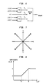
- FIG. 6 A diagram of the 1 D FMH filter with a window of size 5 is shown in Figure 6.
- an index i where i can be E, W, S, N, NE, SW, NW, and SE, is utilized to indicate the direction where the FIR filter is operated and measured from a central input pixel p(x,y).
- the output of each of the three FIR linear phase subfilters p(x,y) is defined as the average taking over the linear direction i.
- a diagram of the linear directions E, W, S, N, NE, SW, NW, and SE, used in the preferred embodiment of the present invention is shown in Figure 7. It is to be understood, however, that additional directions may be utilized.
- equations 12-19 define the outputs of the above-noted FIR linear phase subfilters in a two-dimensional x-y coordinate frame
- the output of the filters is one-dimensional in that the average of all pixels along a direction from (but not including) a center pixel to the pixel at the edge of the window is calculated, thereby utilizing the one-dimensional linear filtering techniques of equations 8-10.
- the FMH filter with different root structures is applied to the pixels in each class.
- p(x,y) as the center pixel within a square window with size (2L+1)x(2L+1).
- the output of filter 1 to filter 4 is defined as where p filter *(x,y) is the overall output taken over the median of the outputs of three FIR linear phase subfilters p(x,y) along the direction of the determined edge orientation.
- a two dimensional (2D) low-pass filter 5 is used for nonedge pixels. If p(x,y) is the center pixel within a square window with size (2L + 1) x (2L + 1), then the output of the filter is
- the spatially filtered video sequence is further filtered at block 110 temporally.
- Motion-compensated temporal filtering is performed particularly because such filtering will enhance artifact reduction in the moving areas of an image.
- motion information is needed. Theoretically, estimates regarding either forward motion information or backward motion information from the reconstructed image sequences may be utilized. However, as motion estimation can often be very complicated and therefore very expensive to compute, it is advantageous to not compute the motion vectors separately. Instead, the motion vectors extracted for decoding can be stored and reused for postprocessing.
- Figure 8 shows the diagram of the temporal filter block 110 and frame buffer 108.
- frame buffer 108 is used to store spatially filtered video frames 107.
- frame buffer 108 can store at least 3 frames: the current frame f n , the previous frame f n- 1 , and the future frame f n+1 . Buffer 108 yields these stored frames as signal 109 to temporal filter 110.
- the pixel at spatial location (i,j) in frame n is defined as p n (i,j).
- the pixel in frame n+1 is defined as p n+1 (i,j)
- P n - l (i,j) is the pixel in the previous best matching frame E n-i .
- the previous best matching frame consists of macroblocks from either the previous frame n-1 or the motion-compensated frame.
- P n-1 (i,j) is then defined as where p n-1 (i,j) is the pixel from the motion-compensated macroblock of a 16 x 16 group of pixels, and p n-1 (i,j) is the pixel from the previous frame n-1.
- No_mc_SE and mc_SE are error powers between the motion-compensated block, and the previous block, respectively. These terms are defined as follows:
- frame difference e between the current frame f n and the previous best matching frame f n-1 is calculated at first temporal subprocessor 20. Then, the frame difference e at the location (i,j) is computed as
- the frame difference e(i,j) between the current frame f n and the previous best matching frame f n- 1 is sent to nonlinear mapper 22 where the coefficient a, a weighting factor, is determined based on the frame difference e(i,j).
- the weighting factors a(i,j) for each pixel in an i-by-j matrix of pixels are multiplied by the frame difference e for each pixel by a second temporal subprocessor 21 and then added by a third temporal subprocessor 23 to the corresponding pixel of the previous best matching frame fn- to obtain an intermediate weighted average current pixel Pn (i,j) of an intermediate weighted average current frame in (i,j) .
- Asecond frame difference e' between the weighted average pixel P n (i,j) and the pixel p n+i from the future frame f n+i is computed by a fourth temporal subprocessor 24 as
- the second frame difference e' is then used by nonlinear filter 25 to obtain a second weighting factor ⁇ in the same manner as a was obtained.
- the weighting factors ⁇ (i,j) for each pixel in an i-by-j matrix of pixels are multiplied by the frame difference e' for each pixel by a fifth temporal subprocessor 26.
- a filtered pixel P ⁇ n (i,j) is calculated at sixth temporal subprocessor 27 as a weighted average of the intermediate pixel P ⁇ n (i,j) and the future adjacent pixel p n+1 .
- each of the aforementioned temporal subprocessors 20, 21, 23, 24, 26, and 27 as well as the non-linear mappers 22 and 25 are preferably implemented by the processor which performs the functions of postfilter 100 or, in the alternative, may implemented by separate standard processors such as an 80386.
- T a and T b are predetermined thresholds determined from experimental data.
- the pixel value is in the range of 0 to 255. Accordingly, in the preferred embodiment, a is selected from the range 0.1 to 1, ⁇ is selected from the range 0.1 to 1, T a is equal to a threshold of 9, and T b is equal to a threshold of 40. If e or e' is less than T a , meaning that there is not much movement in the current pixel, or the motion of the current pixel is well tracked, then simple pixel averaging is applied.
- the pixel in the filtered frame can be obtained by using the following equations: where P ⁇ n (i,j) is the pixel in the filtered frame.
- Filtered signal 111 contains a sequence of filtered pixels P ⁇ n (i,j). This filtered signal 111 is then sent to the display device 113.
- the features of the present invention include the use of a separable 3D filtering structure: space-variant FIR-Median hybrid filtering is used in the spatial domain, followed by motion-compensated nonlinear filtering in the temporal domain.
- the present invention provides spatial and temporal operations which are adaptive to the local statistics of the signal, both spatially and temporally.
- spatial operations switch between linear and nonlinear filtering depending on the edge/nonedge orientation of a signal and temporal operations account for motion compensated signals.
- the aforementioned filtering structure optimizes the filtering process by using cost-efficient and simplified one-dimensional spatial filtering techniques.
Abstract
A 3D nonlinear postprocessing system and method are utilized to reduce coding artifacts produced by block-based motion-compensated transform coding. In the system and method, a separable 3D filtering structure is used: space-variant FIR-Median Hybrid filtering (in 106) is used in the spatial domain, followed by a motion-compensated (on 112) nonlinear filtering in the temporal domain (in 110). By using this structure and method, the coding artifacts in a reconstructed image sequence can be effectively reduced without blurring edges or moving objects in the image sequence. Significant improvement in the picture quality of low bit-rate coded video sequences (111) is thereby achieved.
Description
- The present invention relates generally to the field of digital video processing and, more particularly, to a system and method for post-processing decompressed motion video sequences where a block-based motion-compensated transform coding technique is used for compression and decompression.
- Video images can be represented by a digital signal in which a series of bits of information is used to represent each video frame. Where the bandwidth of a particular communication system is limited, such as in the integrated services digital network (ISDN) or the public telephone network, low bit-rate image coding is particularly useful for transmitting visual images and communications. As such, increasing demands have been placed on the use of low bit-rate coding. Low bit-rates between px9.6 kbit/s and px384 kbit/s are most frequently used for low bit-rate transmissions. As demands increase, the picture quality of video images generated through low bit-rate coding becomes critical.
- Coded picture quality is generally determined by the type of coding technique used and the targeted bit rate. Coding processes, however, have inherent loss characteristics. Image coding often results in noise or spurious signals upon reconstruction of the image. Noise and spurious signals that occur as a result of such imaging techniques are often referred to as artifacts. Artifacts can often reach a level where they appear in the video image with as much strength as the signals produced by the real objects of the image. Moreover, artifacts often become even more visible for low bit-rate transmissions.
- The characteristics of these artifacts depend on the form of coding technique used. Currently, the most well-known and popular low bit-rate coding technique involves block-based motion-compensated transform coding. Such a coding technique is used in many image compression standards, such as the CCITT (Consultative Committee on International Telegraphy and Telephony) Recommendation H.261, Draft Revised Recommendation H.261-Video Codec for Audiovisual Services at px64 kbit/s, Study Group XV-Report R95 (May 1992), herein incorporated by reference, and the more recent proposals arising out of the Telecommunication Standardization Sector Study Group 15, Working Party 15/1 Expert's Group on Very Low Bitrate Videophone (LBC-93), herein incorporated by reference.
- This CCITT standard, although an image compression standard often used for multimedia applications, produces highly noticeable artifacts upon reconstruction of an image at low bit-rate. Those artifacts are often referred to as "blocking effects", "quantization noise" and the "mosquito phenomenon". Future standards using block-based motion-compensated transform coding will likely also produce such artifacts.
- "Blocking effects" are spatial domain distortions which appear as discontinuities on the edges of an image and which yield average values of luminance and chrominance across a block boundary, a so-called spatial artifact. These distortions are caused by using different coding parameters for adjacent blocks. For blocks containing edges, edges can be discontinuous on block boundaries since each block is coded independently of its neighbors. Similarly, for monotone blocks where the intensity in the original image changes gradually, the intensity in the coded blocks can change abruptly from one block to another, due to the different quantization parameters used for each block.
- "Quantization noise" is a distortion caused by quantization processes. When a quantization step size is small, the distortion caused by the quantization is called granular noise, a noise with a high spatial frequency that is evenly distributed over an entire block. This noise is independent of the signal. When a quantization step size is large, the quantization noise is signal-dependent since the signal can be all mapped to zero. Where large quantization forces the high frequency components to zero, the artifacts can be described as "noise contour". Various coefficients used in Discrete Cosine Transform (DCT) techniques may cause this distortion to spread over the entire block when the edge block is transformed into the DCT domain, particularly in view of the fact that DCT techniques are inefficient in representing edges compared with flat areas. Significant losses in edge information and the creation of speckle-like distortions near the edges of a particular block may occur as a direct result of coarse quantization of the DCT coefficients.
- The "mosquito phenomenon" is a high frequency granular type of noise, which appears similar to a moving cloud of insects, that is caused by motion compensation and quantization processes. This phenomenon is a distortion which appears in the temporal domain, a so-called temporal artifact. These artifacts further degrade reconstructed picture quality.
- Therefore, to improve the reconstructed picture quality, postprocessing to reduce the aforementioned artifacts is frequently necessary.
- There have been many nonlinear postprocessing techniques proposed for reducing coding artifacts and for improving reconstructed picture quality. For example, in an article published by B. Ramamurthi and A. Ger- sho, "Nonlinear Space-Variant Postprocessing of Block Coded Images", IEEE Trans. on Acoustics, Speech, and Signal Processing, VOL. ASSP-34, No. 5, October 1986, the authors proposed a space-variant nonlinear postprocessing technique.
- Similarly, in articles published by R.L. Stevenson, "Reduction of Coding Artifacts in Transform Image Coding", Proceedings of the International Conference on Acoustics, Speech, and Signal Processing, 1993; and A. Zakhor, "Iterative Procedures for Reduction of Blocking Effects in Transform Image Coding", IEEE Transactions on Circuits and Systems for Video Technology, Vol. 2, No. 1, March 1992, pp. 91-95, Lee et al., "Post- processing of Video Sequence Using Motion Dependent Median Filters," SPIE Vol. 1606 Visual Communications and Image Processing '91, Image Processing, July 1991, among others, the authors proposed various techniques for improving picture quality.
- However, the aforementioned proposed techniques were designed to reduce artifacts produced by either still image coding techniques, where no motion compensation is employed, or other coding techniques which do not utilize block-based motion-compensated transform coding.
- In addition, in articles published by A. Nieminen, P. Heinonen, and Y. Neuvo, "A New Class of Detail-Preserving Filters for Image Processing", IEEE Trans. on Pattern Analysis and Machine Intelligence, VOL. PAMI-9, No. 1, Jan. 1987, and P. Heinonen, "FIR-Median Hybrid Filters", IEEE Trans. on Acoustics, Speech and Signal Processing, VOL. ASSP-35, No. 6, June 1987, various filtering techniques have also been proposed.
- Different coding techniques produce different artifacts. As such, motion-compensated coding techniques often introduce different spatial and temporal artifacts on the reconstructed picture. Techniques proposed by these various authors are unnecessarily complex and often fail to account for the different spatial and temporal artifacts produced by block-based motion-compensated transform coding. As such, the various techniques proposed to date are not particularly efficient for eliminating spatial and temporal artifacts from decompressed signals generated by block-based motion-compensated transform coding.
- The present invention achieves many advantages and contains features for efficiently reducing artifacts introduced into video images by block-based motion-compensated transform coding. One feature of the present invention includes the ability to optimize video images transmitted at low bit-rates. Another feature includes the ability to adapt spatial and temporal filtering to local signal statistics.
- These and otherfeatures of the present invention achieve significant reduction in coding artifacts without blurring or distorting (1) the edges of video images and (2) moving objects in the image sequence.
- In addition, the present invention achieves the advantages associated with the use of low-cost filtering techniques, which are not unnecessarily complex, to optimize video picture quality.
- The present invention provides a system and method for enhancing decompressed motion video sequences, where the compression technique involves block-based motion-compensated transform coding.
- In one embodiment of the present invention, a separable 3D filtering structure is used: space-variant FIR-Median hybrid filtering is used in the spatial domain, followed by motion-compensated nonlinearfiltering in the temporal domain. By using this structure, the coding artifacts in the reconstructed image sequence can be effectively reduced without blurring edges or moving objects in the image sequence.
- In addition, the present invention provides spatial and temporal operations which are adaptive to the local statistics of the signal, both spatially and temporally. One-dimensional spatial operations for edge oriented pixels and two-dimensional spatial operations for nonedge pixels are followed by motion compensated nonlinear temporal filtering to optimize a reconstructed picture.
- In particular, the present invention provides spatial operations which switch between linear and nonlinear filtering depending on the spatial local statistics of the signal. Specifically, a two-dimensional low-pass filter is used for flat areas and one-dimensional space-variant FIR-Median hybrid filters are used for edge areas. The FIR-Median hybrid filter is designed so its root structure is parallel with the direction of the edge orientation. The particular use of one-dimensional FIR-Median Hybrid filters with root structures parallel to the edge orientation achieves significant reduction in spatial artifacts on edge areas, thereby enhancing the definition and clarity of the edges without blurring the image.
- In addition, the present invention includes a system and method for adaptive motion-compensated frame averaging, thereby reducing temporal artifacts without causing blurring of a moving object.
- These, together with other features and advantages which will be subsequently apparent, reside in the details of construction and operation as more fully hereinafter described and claimed, with reference being had to the accompanying drawings forming a part hereof, wherein like numerals refer to like elements throughout.
-
- Figure 1 is block diagram illustrating the basic operation of a video decoder with the postprocessing filtering system and method of the preferred embodiment of the present invention;
- Figure 2 is a block diagram illustrating the postprocessing filtering system and method of the preferred embodiment of the present invention.
- Figure 3 is a block diagram illustrating the system and method of edge orientation detection performed by the preferred embodiment of the present invention.
- Figure 4 is a block diagram illustrating the system and method of spatial filtering performed by the preferred embodiment of the present invention.
- Figure 5 is a diagram of the line structures parallel to the root structures of the spatial filters depicted in Figure 4.
- Figure 6 is a diagram of the one-dimensional Finite-Impulse-Response-Median hybrid (FMH) filter utilized in the preferred embodiment of the present invention.
- Figure 7 is a diagram of the directions for use in determining the average taking of the Finite Impulse Response (FIR) linear phase subfilters of the preferred embodiment of the present invention.
- Figure 8 is a block diagram of the temporal filtering and storage system and method of the preferred embodiment of the invention.
- Figure 9 is a chart illustrating the weighting factor coefficients of the temporal filter, a and (3, of the preferred embodiment of the present invention.
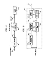
- Figure 1 is a simplified block diagram of a video decoder in use with the postfilter implementing the system and techniques of the present invention. A
video bit stream 98 is supplied as input to thedecoder 99, where the bit stream is decoded and the reconstructeddigital video sequence 101 is produced.Signals 112 are motion vectors decoded from the video bitstream atdecoder 99. Thedecoder 99 uses a block-based motion-compensated transform coding technique such as the technique utilized in H.261. The reconstructeddigital video signal 101 and themotion information 112 are supplied to thepostfilter 100 to produce a coding-artifacts-reduced-video-sequence 111. Coding-artifacts-reduced-video-sequence 111 is then displayed on adisplay device 113.Postfilter 100 is a postprocessor in that it processes information from a decoded and reconstructedvideo sequence 101. - Figure 2 is a block diagram of the
postfilter 100 implementing the techniques of the present invention. Thepostfilter 100 comprises generally the following components: anedge orientation detector 102, an edge/nonedge decision subprocessor 104, aspatial filter bank 106, aframe buffer 108, and atemporal filter 110, each of which will be described in greater detail below. -
Postfilter 100 which implements all of the decision processes of the present invention is preferably a digital signal processor such as a model DSP 3210 manufactured by AT&T. An 80386 type processor manufactured by Intel@ and other types of processors may also be used. In the alternative, each of the aforementioned components which implement various portions of the filtering processes ofpostfilter 100 may be separate processors. - With continuing reference to Figure 2, the general operation of the
postfilter 100 will now be described. Areconstructed video sequence 101 is first supplied as input to block 102, an edge orientation detector, where the edge orientation of each pixel in a video frame is detected. Edge orientation information is supplied as aninput signal 103 to block 104, an edge/nonedge decision subprocessor, where theedge orientation signal 103 is compared with a predetermined threshold Tg to produce acontrol signal 105. - The
control signal 105 controls a bank of spatial filters atblock 106. Atblock 106, theinput signal 101 is filtered by the filter selected according to signal 105. The spatial filter bank atblock 106 produces asignal 107 which comprises spatially filtered video frames. Spatially filtered video frames 107 are then stored atbuffer 108.Buffer 108 is designed to store within its memory at least three temporal frames for subsequent temporal filtering. The three temporal frames consist of at least the following frames: a current frame, a previous frame, and a future frame. Buffer 108 yields its stored video frames asSignal 109. Atblock 110, the current video frame is filtered by using motion information, fromsignal 112, and the previous and the future spatially filtered frames to producesignal 111.Signal 111 is the final filtered video signal which is then transmitted to adisplay device 113. - Figure 3 is a block diagram of an
edge orientation detector 102. An unfiltered video frame is represented as f(x,y). A pixel in this unfiltered video frame is represented as p(x,y). For each pixel p(x,y), the edge orientations can be at one of four angles: 0°, 45°, 90°, and 135°. To compute the edge orientation at each point (x,y), a set of template gradient impulse response arrays Hi is used. The template gradient impulse response arrays {H, i=1,.., 4} are defined as

H1 is the impulse response for the horizontal (O°) gradient, H2 is the impulse response for the 45° gradient, H3 is the impulse response for the vertical (90°) gradient, and H4 is the impulse response for 135° gradient. The edge template gradient at any point (x,y) is defined as
where
is the gradient in the mth equispace direction obtained by convolving the image f(x,y) with a gradient impulse response array {H, i = 1, ..., 4}. The edge angle is determined by the direction of the largest gradient Gmax(x,y) insignal 103.Edge orientation detector 102 performs the above processing to determine the edge orientation of each pixel in thevideo bitstream 98 decoded byvideo decoder 99. -
Signal 103 is supplied to the edge/nonedge decision subprocessor 104 to producecontrol signal 105. At edge/nonedge decision subprocessor 104, in order to determine whether the pixel belongs to the edge or nonedge class, the maximum gradient Gmax(x,y) of the pixel p(x,y) insignal 103, is compared with a predetermined threshold Tg. The predetermined threshold Tg is a value selected from experimental data. In the preferred embodiment, where H.261 guidelines are used, the pixel value is in the range of 0 to 255. Accordingly, in the preferred embodiment, Tg is equal to a threshold of 20. If Gmax(x,y) > Tg, then the pixel at position (x,y) belongs to the edge class with an edge orientation determined by the direction of the greatest gradient Gmax(x,y); otherwise, the pixel at (x,y) belongs to the nonedge class. - The edge or
nonedge indication signal 105 is supplied tospatial filter bank 106. The edge/nonedge indication signal 105 indicates the specific edge orientation (i.e., 0°, 45°, 90°, 135°) or that the signal is not an edge signal. - Figure 4 is a block diagram of the
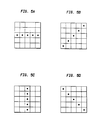
spatial filter bank 106. Thespatial filter bank 106 preferably consists of five filters.Filter 1 toFilter 4 are one-dimensional (1 D) FIR-Median Hybrid (FMH) filters with root structures parallel to the line structures shown in Figure 5. - If the edge orientation is determined to be 0° (Figure 5a),
filter 1 is selected; if the edge orientation is 45° (Figure 5b),filter 2 is selected; if the edge orientation is 90° (Figure 5c),filter 3 is selected; if the edge orientation is 135° (Figure 5d),filter 4 is selected. For a nonedge pixel,filter 5 is selected. The decision to process the signal as an edge or a nonedge signal is controlled by edge/nonedge signal 105, as discussed above. - Generally, the 1D FMH filter used in the preferred embodiment of the present invention consists of 3 linear phase FIR filters and a median filter, although it is to be understood that the number of the FIR filters may be altered. The transfer functions of the three linear phase FIR filters of the preferred embodiment are as follows:


where the window length is (2L+1). For example, if p(c) is the center pixel along a line within a window having a length of (2L+1), then the outputs of the three FIR filters are
- Essentially, therefore, the output of the first FIR filter p1 is a function of the sum of all pixels along a line from (but not including) center pixel p(c) to the pixel at the edge of the window, p(c+L). Similarly, the output of the third FIR filter p3 is a function of the sum of all pixels along the same line from (but not including) center pixel p(c) to the pixel at the opposite edge of the window, p(c-L). Meanwhile, the output of the center filter, p2, is simply equal to center pixel p(c).
- These filters are one-dimensional in that only one variable is utilized for incremental movement (pixel by pixel) along a predetermined fixed line. Thus, even though movement may occur in both the x and y directions (when a predetermined diagonal line is utilized) of a two-dimensional x-y coordinate frame, these filters utilize only a one-dimensional reference frame and therefore achieve the simplicity of a one-dimensional linear filtering technique.
- The output of the FMH filter is

- A diagram of the 1 D FMH filter with a window of
size 5 is shown in Figure 6. - In the preferred embodiment of the present invention, an index i, where i can be E, W, S, N, NE, SW, NW, and SE, is utilized to indicate the direction where the FIR filter is operated and measured from a central input pixel p(x,y). The output of each of the three FIR linear phase subfilters p(x,y) is defined as the average taking over the linear direction i. A diagram of the linear directions E, W, S, N, NE, SW, NW, and SE, used in the preferred embodiment of the present invention is shown in Figure 7. It is to be understood, however, that additional directions may be utilized.
- The output of the FIR linear phase subfilters pi(x,y) in the directions shown in Figure 7 are therefore defined as


- However, it is to be understood that although equations 12-19 define the outputs of the above-noted FIR linear phase subfilters in a two-dimensional x-y coordinate frame, the output of the filters is one-dimensional in that the average of all pixels along a direction from (but not including) a center pixel to the pixel at the edge of the window is calculated, thereby utilizing the one-dimensional linear filtering techniques of equations 8-10.
- As there are four edge classes with edge orientations O°, 45°, 90°, and 135°, the FMH filter with different root structures is applied to the pixels in each class. With p(x,y) as the center pixel within a square window with size (2L+1)x(2L+1). the output of
filter 1 to filter 4 is defined as


where pfilter*(x,y) is the overall output taken over the median of the outputs of three FIR linear phase subfilters p(x,y) along the direction of the determined edge orientation. - While the aforementioned filtering techniques are used for edge pixels, a two dimensional (2D) low-
pass filter 5 is used for nonedge pixels. If p(x,y) is the center pixel within a square window with size (2L + 1) x (2L + 1), then the output of the filter is
- To further reduce the coding artifacts, the spatially filtered video sequence is further filtered at
block 110 temporally. Motion-compensated temporal filtering is performed particularly because such filtering will enhance artifact reduction in the moving areas of an image. To implement motion-compensated temporal filtering, motion information is needed. Theoretically, estimates regarding either forward motion information or backward motion information from the reconstructed image sequences may be utilized. However, as motion estimation can often be very complicated and therefore very expensive to compute, it is advantageous to not compute the motion vectors separately. Instead, the motion vectors extracted for decoding can be stored and reused for postprocessing. In most low-bit rate coding techniques such as H.261, block-based forward motion vectors are available, and these motion vectors can be extracted from the coded bitstream and stored for later postprocessing. The motion information used here is represented bysignal 112. Additional disclosure regarding such motion vectors may be found within CCITT recommendation H.261 and a publication by A. Netravali and B. Haskell, "Digital Pictures Representation and Compression," Plenum Press: New York, 1989. - Figure 8 shows the diagram of the
temporal filter block 110 andframe buffer 108. As temporal filtering involves more than one frame,frame buffer 108 is used to store spatially filtered video frames 107. In the preferred embodiment,frame buffer 108 can store at least 3 frames: the current frame fn, the previous frame fn- 1, and the future frame fn+1. Buffer 108 yields these stored frames assignal 109 totemporal filter 110. - The pixel at spatial location (i,j) in frame n is defined as pn(i,j). Similarly, the pixel in frame n+1 is defined as pn+1(i,j), and Pn-l (i,j) is the pixel in the previous best matching frame En-i . The previous best matching frame consists of macroblocks from either the previous frame n-1 or the motion-compensated frame. Pn-1 (i,j) is then defined as

wherep n-1(i,j) is the pixel from the motion-compensated macroblock of a 16 x 16 group of pixels, and pn-1 (i,j) is the pixel from the previous frame n-1. No_mc_SE and mc_SE are error powers between the motion-compensated block, and the previous block, respectively. These terms are defined as follows:

- With continuing reference to Figure 8, frame difference e between the current frame fn and the previous best matching frame fn-1 is calculated at first
temporal subprocessor 20. Then, the frame difference e at the location (i,j) is computed as
- The frame difference e(i,j) between the current frame fn and the previous best matching frame fn-1 is sent to
nonlinear mapper 22 where the coefficient a, a weighting factor, is determined based on the frame difference e(i,j). - The weighting factors a(i,j) for each pixel in an i-by-j matrix of pixels are multiplied by the frame difference e for each pixel by a second
temporal subprocessor 21 and then added by a thirdtemporal subprocessor 23 to the corresponding pixel of the previous best matching frame fn- to obtain an intermediate weighted average current pixel Pn (i,j) of an intermediate weighted average current frame in (i,j) . - Asecond frame difference e' between the weighted average pixel Pn (i,j) and the pixel pn+i from the future frame fn+i is computed by a fourth
temporal subprocessor 24 as
- The second frame difference e' is then used by
nonlinear filter 25 to obtain a second weighting factor β in the same manner as a was obtained. - The weighting factors β(i,j) for each pixel in an i-by-j matrix of pixels are multiplied by the frame difference e' for each pixel by a fifth
temporal subprocessor 26. - A filtered pixel P̂n(i,j) is calculated at sixth
temporal subprocessor 27 as a weighted average of the intermediate pixel P̂n (i,j) and the future adjacent pixel pn+1. - The function(s) of each of the aforementioned
temporal subprocessors non-linear mappers postfilter 100 or, in the alternative, may implemented by separate standard processors such as an 80386. - The coefficients of the temporal filter, a and β, follow the nonlinear relationship shown in Figure 9. Ta and Tb are predetermined thresholds determined from experimental data. In the preferred embodiment where H.261 guidelines are used, the pixel value is in the range of 0 to 255. Accordingly, in the preferred embodiment, a is selected from the range 0.1 to 1, β is selected from the range 0.1 to 1, Ta is equal to a threshold of 9, and Tb is equal to a threshold of 40. If e or e' is less than Ta, meaning that there is not much movement in the current pixel, or the motion of the current pixel is well tracked, then simple pixel averaging is applied. If e or e' is larger than Tb, indicating that there is a scene change or there is fast movement which can not be tracked by the motion vectors, no operation is applied. If e is between Ta and Tb, the current pixel is in a transition area and weighted averaging is applied. By using this operation, the moving portion of an image can be well-preserved and noise can be effectively reduced.
- The pixel in the filtered frame can be obtained by using the following equations:


where P̂n(i,j) is the pixel in the filtered frame. Filteredsignal 111 contains a sequence of filtered pixels P̂n(i,j). Thisfiltered signal 111 is then sent to thedisplay device 113. - Therefore, in summary, the features of the present invention include the use of a separable 3D filtering structure: space-variant FIR-Median hybrid filtering is used in the spatial domain, followed by motion-compensated nonlinear filtering in the temporal domain. As such, the present invention provides spatial and temporal operations which are adaptive to the local statistics of the signal, both spatially and temporally. In particular, spatial operations switch between linear and nonlinear filtering depending on the edge/nonedge orientation of a signal and temporal operations account for motion compensated signals. Moreover, the aforementioned filtering structure optimizes the filtering process by using cost-efficient and simplified one-dimensional spatial filtering techniques.
- The many features and advantages of the invention are apparent from the detailed specification, and thus, it is intended by the appended claims to cover all such features and advantages of the invention which fall within the true spirit and scope of the invention. Further, since numerous modifications and variations will readily occur to those skilled in the art; it is not desired to limit the invention to the exact construction and operation illustrated and described, and accordingly, all suitable modifications and equivalents may be resorted to, falling within the scope of the invention.
Claims (14)
1. A filtering system for reducing artifacts in motion video sequences generated by block-based motion-compensated transform coding from a video decoder, comprising:
a postprocessor connected to said video decoder, said postprocessor including: an edge orientation detector; a spatial filter bank, said spatial filter bank being configured to receive information from said edge orientation detector, said filter bank comprising a one-dimensional filter utilizing said information to generate spatially filtered video sequences;
and a motion-compensated temporal filter, said motion-compensated temporal filter receiving spatially filtered video sequences generated by said spatial filter bank, said motion-compensated temporal filter being configured to generate temporally filtered video sequences from said spatially filtered video sequences; and
a frame memory connected to said postprocessor, said frame memory being arranged to receive spatially filtered video sequences from said spatial filter bank.
2. The filtering system of claim 1 wherein said edge orientation detector utilizes a set of template gradient impulse response arrays to compute edge orientation.
3. The filtering system of claim 1 wherein said spatial filter bank comprises at least two finite impulse response linear phase filters and a median filter.
4. The filtering system of claim 1 wherein said spatial filter bank further comprises a two dimensional low-pass filter for filtering nonedge pixels in said motion video sequence.
5. The filtering system of claim 1 wherein said frame memory is configured to store signals for a current frame, an adjacent prior frame and an adjacent future frame.
6. The filtering system of claim 8 wherein said motion-compensated temporal filter is configured to:
determine a best matching frame from said adjacent priorframe and a motion-compensated frame; and
calculate a frame difference between a current frame and said best matching frame.
7. A system for filtering decoded noise-contaminated signals for video communication, comprising:
a computer processor;
means for filtering spatial artifacts from decoded noise-contaminated signals, said means for filtering spatial artifacts comprising an edge detector and a one-dimensional filter;
means for storing signals from said decoded noise-contaminated signals for at least a current frame, a prior frame and a future frame;
means for calculating a best matching frame from said prior frame and a motion-compensated frame;
means for calculating an intermediate weighted average current frame from said current frame and a best matching frame, such that the best matching frame is given less weight as the difference between said intermediate weighted average current frame and said motion-compensated prior frame increases; and
means for calculating a filtered frame from a weighted average of the intermediate weighted average current frame and said future frame, such that said future frame is given less weight as the difference between said intermediate weighted average current frame and said future frame increases.
8. A three dimensional filter system for enhancing decompressed motion video sequences generated by block-based motion-compensated transform coding, comprising:
a one-dimensional space-variant FIR-median hybrid filter, said one-dimensional space-variant FIR-median hybrid filter being structured to reduce the effect of spatial artifacts generated by block-based motion-compensated transform coding on said motion video sequences;
a memory to store least a portion of said motion video sequences, said memory being connected to said one-dimensional space-variant FIR-median hybrid filter; and
a motion-compensated nonlinear filter, said motion-compensated nonlinear filter being structured to reduce the effect of temporal artifacts generated by block-based motion-compensated transform coding on said motion video sequences;
wherein said one-dimensional space-variant FIR-median hybrid filter, said memory and said motion-compensated nonlinear filter are arranged in series.
9. The filter system of claim 8 further comprising:
a one-dimensional edge detector, said edge detector being configured to input information to said space-variant FIR-median hybrid filter to reduce the effect of spatial artifacts.
10. A method of processing and displaying decoded video image sequence signals generated by block-based motion-compensated transform coding, comprising the steps of:
detecting the edge orientation of a pixel of said video image sequences;
filtering spatial artifacts from said video image sequences using a one-dimensional filter for pixels determined to have an orientation in an edge region of said video sequence signals;
storing at least a current frame, an adjacent prior frame and an adjacent future frame from said video image sequence signals;
calculating a temporally filtered frame from a weighted average of said adjacent future frame, said current frame and a motion-compensated adjacent prior frame; and
displaying said temporally filtered frame.
11. The method of claim 10 wherein said step of calculating a temporally filtered frame further comprises the steps of:
calculating a best matching frame;
calculating a frame difference between said current frame and said best matching frame;
determining a weighting factor based, at least in part, on said frame difference;
calculating a weighted average current frame from the current frame and said best matching frame, based, at least in part, on the weighting factor.
12. The method of claim 10 wherein said step of detecting the edge orientation of a pixel comprises the steps of:
convolving said pixel with a gradient impulse response array;
determining a maximum gradient; and comparing said maximum gradient to a threshold to determine whether a pixel belongs in an edge region or a nonedge region.
13. The method of claim 10 wherein said step of filtering spatial artifacts from said video image sequences comprises the step of:
filtering spatial artifacts from said video image sequences using a two-dimensional low-pass filter for pixels determined to have an orientation in a nonedge region of said video sequences.
14. The method of claim 10 wherein said step of filtering spatial artifacts further comprises the steps of:
selecting a direction from a pixel at the edge region p(c+L) through a center pixel p(c) to a second pixel at the edge region p(c-L);
calculating the output of a first finite impulse response filter as a function of a center pixel p(c) and all pixels from p(c) to p(c+L) along said direction;
calculating the output of a second finite impulse response filter as a function of center pixel p(c); and
calculating the output of a third finite impulse response filter as a function of all pixels from p(c-1) to p(c-L) along said direction;
wherein L is equal to (window length-I)/2.
Applications Claiming Priority (2)
| Application Number | Priority Date | Filing Date | Title |
|---|---|---|---|
| US08/191,685 US5512956A (en) | 1994-02-04 | 1994-02-04 | Adaptive spatial-temporal postprocessing for low bit-rate coded image sequences |
| US191685 | 1994-02-04 |
Publications (2)
| Publication Number | Publication Date |
|---|---|
| EP0666695A2 true EP0666695A2 (en) | 1995-08-09 |
| EP0666695A3 EP0666695A3 (en) | 1996-03-06 |
Family
ID=22706517
Family Applications (1)
| Application Number | Title | Priority Date | Filing Date |
|---|---|---|---|
| EP95300477A Withdrawn EP0666695A3 (en) | 1994-02-04 | 1995-01-26 | Adaptive spatial-temporal postprocessing for low bit-rate coded image sequences. |
Country Status (3)
| Country | Link |
|---|---|
| US (1) | US5512956A (en) |
| EP (1) | EP0666695A3 (en) |
| JP (1) | JPH07231450A (en) |
Cited By (15)
| Publication number | Priority date | Publication date | Assignee | Title |
|---|---|---|---|---|
| DE19626985C1 (en) * | 1996-07-04 | 1998-01-02 | Siemens Ag | Method and arrangement for reducing coding artifacts of block-based image coding methods and object-based image coding methods |
| GB2325583A (en) * | 1997-04-10 | 1998-11-25 | Samsung Electronics Co Ltd | Post-processing removal of blocking artefacts from a block-based image by filtering |
| EP0781053A3 (en) * | 1995-12-18 | 1999-04-21 | Lucent Technologies Inc. | Method and apparatus for post-processing images |
| EP0917357A1 (en) * | 1997-05-28 | 1999-05-19 | Sony Corporation | Block distortion reduction method and device and encoding method and device |
| EP0817497A3 (en) * | 1996-07-06 | 1999-12-29 | Samsung Electronics Co., Ltd. | Loop filtering method for reducing blocking effects and ringing noise of a motion-compensated image |
| EP0797349A3 (en) * | 1996-03-23 | 1999-12-29 | Samsung Electronics Co., Ltd. | Signal adaptive postprocessing system for reducing blocking effects and ringing noise |
| EP1146748A2 (en) * | 2000-03-31 | 2001-10-17 | Sharp Kabushiki Kaisha | A method of directional filtering for post-processing compressed video |
| WO2004010706A1 (en) | 2002-07-19 | 2004-01-29 | Sony Corporation | Information signal processing device, information signal processing method, image signal processing device, image displaying device, device and method for producing correction data used in them, device and method for producing coefficient data, programs for executing these methods, and computer-readable medium in which thos |
| WO2004080084A1 (en) * | 2003-03-03 | 2004-09-16 | Agency For Science, Technology And Research | Fast mode decision algorithm for intra prediction for advanced video coding |
| WO2006060509A1 (en) * | 2004-12-01 | 2006-06-08 | Hewlett-Packard Development Company, L.P. | Artifact reduction in a digital video |
| EP1445959A3 (en) * | 1997-07-16 | 2006-10-11 | Samsung Electronics Co., Ltd. | Signal adaptive filtering method for filtering ringing noise, signal adaptive filter and computer readable medium for storing program therefor |
| GB2443700A (en) * | 2006-11-10 | 2008-05-14 | Tandberg Television Asa | Reduction of blocking artefacts in decompressed images |
| US7440608B2 (en) | 2005-05-31 | 2008-10-21 | Hewlett-Packard Development Company, L.P. | Method and system for detecting image defects |
| CN102547256A (en) * | 2010-12-10 | 2012-07-04 | 株式会社理光 | Method and system for removing self-adaptive block effect |
| US9036695B2 (en) | 2010-11-02 | 2015-05-19 | Sharp Laboratories Of America, Inc. | Motion-compensated temporal filtering based on variable filter parameters |
Families Citing this family (73)
| Publication number | Priority date | Publication date | Assignee | Title |
|---|---|---|---|---|
| US5841484A (en) * | 1994-02-10 | 1998-11-24 | Philips Electronics North North America Corporation | Blind equalizer method and apparatus for HDTY transmission using an NTSC rejection filter for mitigating co-channel interference |
| JP3529432B2 (en) * | 1994-06-30 | 2004-05-24 | 株式会社東芝 | Video encoding / decoding device |
| JP3634410B2 (en) * | 1994-10-18 | 2005-03-30 | キヤノン株式会社 | Image processing system, image processing apparatus and method |
| US5802218A (en) * | 1994-11-04 | 1998-09-01 | Motorola, Inc. | Method, post-processing filter, and video compression system for suppressing mosquito and blocking atrifacts |
| JPH08163594A (en) * | 1994-12-12 | 1996-06-21 | Sony Corp | Moving image decoding method and moving image decoder |
| US5654759A (en) * | 1995-02-15 | 1997-08-05 | Hitachi America Ltd. | Methods and apparatus for reducing blockiness in decoded video |
| US5852475A (en) * | 1995-06-06 | 1998-12-22 | Compression Labs, Inc. | Transform artifact reduction process |
| US6324301B1 (en) * | 1996-01-24 | 2001-11-27 | Lucent Technologies Inc. | Adaptive postfilter for low bitrate visual telephony noise removal |
| US5793985A (en) * | 1996-06-17 | 1998-08-11 | Hewlett-Packard Company | Method and apparatus for block-based motion estimation |
| US5912991A (en) * | 1997-02-07 | 1999-06-15 | Samsung Electronics Co., Ltd. | Contour encoding method using error bands |
| JP3274980B2 (en) * | 1997-03-03 | 2002-04-15 | 株式会社ケンウッド | Two-dimensional video filter and video filter device |
| US5959693A (en) * | 1997-05-07 | 1999-09-28 | General Instrument Corporation | Pixel adaptive noise reduction filter for digital video |
| US6067125A (en) * | 1997-05-15 | 2000-05-23 | Minerva Systems | Structure and method for film grain noise reduction |
| US5920359A (en) * | 1997-05-19 | 1999-07-06 | International Business Machines Corporation | Video encoding method, system and computer program product for optimizing center of picture quality |
| US6335990B1 (en) | 1997-07-03 | 2002-01-01 | Cisco Technology, Inc. | System and method for spatial temporal-filtering for improving compressed digital video |
| GB2333656B (en) * | 1998-01-22 | 2002-08-14 | British Broadcasting Corp | Compressed signals |
| GB2333657B (en) | 1998-01-22 | 2002-08-21 | Snell & Wilcox Ltd | Video signal compression |
| GB2335104B (en) | 1998-03-06 | 2002-01-30 | British Broadcasting Corp | Cascading of up conversion and down conversion |
| GB2337389B (en) * | 1998-05-15 | 2002-05-29 | Snell & Wilcox Ltd | Video signal processing |
| US6327307B1 (en) | 1998-08-07 | 2001-12-04 | Motorola, Inc. | Device, article of manufacture, method, memory, and computer-readable memory for removing video coding errors |
| DE69817824T2 (en) * | 1998-10-05 | 2004-08-12 | Agfa-Gevaert | Process for smoothing the step effect in enlarged images of low resolution |
| GB9822094D0 (en) | 1998-10-09 | 1998-12-02 | Snell & Wilcox Ltd | Improvements in data compression |
| GB9822092D0 (en) | 1998-10-09 | 1998-12-02 | Snell & Wilcox Ltd | Analysis of compression decoded sequences |
| GB9822087D0 (en) * | 1998-10-09 | 1998-12-02 | Snell & Wilcox Ltd | Improvements in data compression |
| GB9824061D0 (en) | 1998-11-03 | 1998-12-30 | Snell & Wilcox Ltd | Film sequence detection (nt4) |
| US6700623B1 (en) | 1998-12-10 | 2004-03-02 | Snell & Wilcox Limited | Video signal processing using triplets of pixels |
| US6434197B1 (en) | 1999-01-07 | 2002-08-13 | General Instrument Corporation | Multi-functional transcoder for compressed bit streams |
| JP2002535896A (en) * | 1999-01-15 | 2002-10-22 | コーニンクレッカ フィリップス エレクトロニクス エヌ ヴィ | Method and apparatus for improving sharpness |
| US6697109B1 (en) * | 1999-05-06 | 2004-02-24 | Sharp Laboratories Of America, Inc. | Method and system for field sequential color image capture |
| US6115409A (en) * | 1999-06-21 | 2000-09-05 | Envoy Networks, Inc. | Integrated adaptive spatial-temporal system for controlling narrowband and wideband sources of interferences in spread spectrum CDMA receivers |
| US6690422B1 (en) * | 1999-11-03 | 2004-02-10 | Sharp Laboratories Of America, Inc. | Method and system for field sequential color image capture using color filter array |
| WO2001069536A2 (en) * | 2000-03-10 | 2001-09-20 | Sarnoff Corporation | Method and apparatus for qualitative spatiotemporal data processing |
| GB2361126B (en) * | 2000-04-05 | 2004-04-21 | Snell & Wilcox Ltd | Spatial video processing |
| US6868190B1 (en) | 2000-10-19 | 2005-03-15 | Eastman Kodak Company | Methods for automatically and semi-automatically transforming digital image data to provide a desired image look |
| US7031393B2 (en) * | 2000-10-20 | 2006-04-18 | Matsushita Electric Industrial Co., Ltd. | Block distortion detection method, block distortion detection apparatus, block distortion removal method, and block distortion removal apparatus |
| KR20020086937A (en) * | 2001-01-26 | 2002-11-20 | 코닌클리케 필립스 일렉트로닉스 엔.브이. | Spatio-temporal filter unit and image display apparatus comprising such a spatio-temporal filter unit |
| US7092016B2 (en) * | 2001-02-09 | 2006-08-15 | Eastman Kodak Company | Method and system for motion image digital processing |
| US7006255B2 (en) * | 2001-03-29 | 2006-02-28 | Sharp Laboratories Of America | Adaptive image filtering based on a distance transform |
| EP1251463A1 (en) * | 2001-04-20 | 2002-10-23 | BTS Media Solutions GmbH | Arrangement for processing video signals |
| CN1294760C (en) * | 2001-06-19 | 2007-01-10 | 皇家菲利浦电子有限公司 | Method and decoder for processing digital video signal |
| KR100444997B1 (en) * | 2002-02-21 | 2004-08-21 | 삼성전자주식회사 | Edge correction method and apparatus therefor |
| US7543326B2 (en) * | 2002-06-10 | 2009-06-02 | Microsoft Corporation | Dynamic rate control |
| US20030235250A1 (en) * | 2002-06-24 | 2003-12-25 | Ankur Varma | Video deblocking |
| EP1391866A1 (en) * | 2002-08-23 | 2004-02-25 | Deutsche Thomson Brandt | Adaptive noise reduction for digital display panels |
| US7151798B2 (en) * | 2002-10-29 | 2006-12-19 | Winbond Electronics Corp. | Method for motion estimation using a low-bit edge image |
| JP4042563B2 (en) * | 2002-12-27 | 2008-02-06 | セイコーエプソン株式会社 | Image noise reduction |
| US7463688B2 (en) * | 2003-01-16 | 2008-12-09 | Samsung Electronics Co., Ltd. | Methods and apparatus for removing blocking artifacts of MPEG signals in real-time video reception |
| KR100782829B1 (en) * | 2003-06-10 | 2007-12-06 | 렌슬러 폴리테크닉 인스티튜트 | A method for processing i-blocks used with motion compensated temporal filtering |
| US20050137911A1 (en) * | 2003-12-18 | 2005-06-23 | Conn John P. | Systems and methods for data insurance |
| US7616220B2 (en) * | 2003-12-23 | 2009-11-10 | Intel Corporation | Spatio-temporal generation of motion blur |
| EP1784810A2 (en) * | 2004-06-14 | 2007-05-16 | Genoa Color Technologies Ltd. | Method, device and system of response time compensation |
| JP2008508751A (en) * | 2004-07-30 | 2008-03-21 | アルゴリス インコーポレイテッド | Apparatus and method for adaptive 3D fictitious video reduction for encoded image signals |
| US20060291743A1 (en) * | 2005-06-24 | 2006-12-28 | Suketu Partiwala | Configurable motion compensation unit |
| CN1971616B (en) * | 2005-11-23 | 2012-10-10 | 索诺塞特公司 | Multi-resolution adaptive filtering |
| JP2007149180A (en) * | 2005-11-25 | 2007-06-14 | Hitachi Ltd | Optical disk device |
| JP4528255B2 (en) * | 2005-12-06 | 2010-08-18 | 日本放送協会 | Video decoding apparatus and video decoding program |
| KR20080010689A (en) * | 2006-07-27 | 2008-01-31 | 삼성전자주식회사 | An image display device and an image display method |
| JP2008244846A (en) * | 2007-03-27 | 2008-10-09 | Toshiba Corp | Device and method for interpolating frame |
| JP5180550B2 (en) * | 2007-09-21 | 2013-04-10 | 株式会社日立製作所 | Image processing apparatus and image processing method |
| US8200028B2 (en) * | 2007-12-07 | 2012-06-12 | Csr Technology Inc. | System and method for detecting edges in a video signal |
| US8295367B2 (en) * | 2008-01-11 | 2012-10-23 | Csr Technology Inc. | Method and apparatus for video signal processing |
| US8781250B2 (en) * | 2008-06-26 | 2014-07-15 | Microsoft Corporation | Image deconvolution using color priors |
| TWI390467B (en) * | 2009-01-23 | 2013-03-21 | Silicon Integrated Sys Corp | Dynamic noise filter and sigma filtering method |
| JP5075861B2 (en) * | 2009-03-16 | 2012-11-21 | 株式会社東芝 | Image processing apparatus and image processing method |
| US8285069B2 (en) * | 2010-03-30 | 2012-10-09 | Chunghwa Picture Tubes, Ltd. | Image processing device and method thereof |
| US20130058421A1 (en) * | 2010-05-17 | 2013-03-07 | Thomson Licensing | Methods and apparatus for adaptive directional filter for video restoration |
| JP5295431B2 (en) * | 2010-07-06 | 2013-09-18 | 三菱電機株式会社 | Image processing device |
| KR101208237B1 (en) | 2010-12-29 | 2012-12-05 | 삼성전기주식회사 | Apparatus and method for reducing noise of digital image |
| JP5242750B2 (en) * | 2011-09-09 | 2013-07-24 | オリンパス株式会社 | Image processing device |
| US10091483B2 (en) * | 2012-06-25 | 2018-10-02 | Thomson Licensing | Method and device for temporal filtering of disparity maps |
| US9002133B2 (en) * | 2013-02-27 | 2015-04-07 | Sharp Laboratories Of America, Inc. | Multi layered image enhancement technique |
| WO2016064879A1 (en) * | 2014-10-20 | 2016-04-28 | Bae Systems Information And Electronic Systems Integration Inc. | Scene-based non-uniformity correction in focal plane arrays |
| CN105208402B (en) * | 2015-08-31 | 2017-12-15 | 电子科技大学 | A kind of frame of video complexity measure method based on Moving Objects and graphical analysis |
Citations (2)
| Publication number | Priority date | Publication date | Assignee | Title |
|---|---|---|---|---|
| WO1991014340A1 (en) * | 1990-03-15 | 1991-09-19 | Thomson Consumer Electronics S.A. | Digital image processing including block edges filtering |
| WO1993022742A1 (en) * | 1992-05-07 | 1993-11-11 | Picturetel Corporation | A method and apparatus for processing block coded image data to reduce boundary artifacts between adjacent image blocks |
Family Cites Families (8)
| Publication number | Priority date | Publication date | Assignee | Title |
|---|---|---|---|---|
| FR2387557A1 (en) * | 1977-04-14 | 1978-11-10 | Telediffusion Fse | NOISE VISIBILITY REDUCTION SYSTEMS ON TELEVISION IMAGES |
| US4352126A (en) * | 1977-04-14 | 1982-09-28 | Jacques Poncin | System for reducing visible noise in television images |
| IL70213A (en) * | 1983-11-13 | 1988-02-29 | Paul Fenster | Digital fluorographic image enhancement system |
| FR2633477B1 (en) * | 1988-06-24 | 1990-11-09 | France Etat | METHOD FOR REGULATING DATA RATE OF ASSISTANCE IN THE RECONSTRUCTION OF SUB-SAMPLE ANIMATED ELECTRONIC IMAGES |
| US4891699A (en) * | 1989-02-23 | 1990-01-02 | Matsushita Electric Industrial Co., Ltd. | Receiving system for band-compression image signal |
| US5134480A (en) * | 1990-08-31 | 1992-07-28 | The Trustees Of Columbia University In The City Of New York | Time-recursive deinterlace processing for television-type signals |
| KR0149517B1 (en) * | 1992-07-18 | 1998-10-15 | 강진구 | Multi-step type nonlinear filter for detecting edge and eliminating noise |
| JPH06121192A (en) * | 1992-10-08 | 1994-04-28 | Sony Corp | Noise removing circuit |
-
1994
- 1994-02-04 US US08/191,685 patent/US5512956A/en not_active Expired - Lifetime
-
1995
- 1995-01-26 EP EP95300477A patent/EP0666695A3/en not_active Withdrawn
- 1995-02-02 JP JP7035876A patent/JPH07231450A/en active Pending
Patent Citations (2)
| Publication number | Priority date | Publication date | Assignee | Title |
|---|---|---|---|---|
| WO1991014340A1 (en) * | 1990-03-15 | 1991-09-19 | Thomson Consumer Electronics S.A. | Digital image processing including block edges filtering |
| WO1993022742A1 (en) * | 1992-05-07 | 1993-11-11 | Picturetel Corporation | A method and apparatus for processing block coded image data to reduce boundary artifacts between adjacent image blocks |
Non-Patent Citations (4)
| Title |
|---|
| IEEE TRANSACTIONS ON ACOUSTICS, SPEECH AND SIGNAL PROCESSING, vol. ASSP-34, no. 5, October 1986 pages 1258-1268, XP 000349257 RAMAMURTHI ET AL 'Nonlinear Space-Variant Postprocessing of Block Coded Images' * |
| IEEE TRANSACTIONS ON ACOUSTICS, SPEECH AND SIGNAL PROCESSING, vol. ASSP-35, no. 6, June 1987 pages 832-838, HEIKONEN ET AL 'FIR-Median Hybrid Filters' * |
| VISUAL COMMUNICATIONS AND IMAGE PROCESSING '91: IMAGE PROCESSING, vol. 1606, November 1991 BOSTON, MA, US, pages 728-734, LEE ET AL 'Postprocessing of Video Sequence Using Motion Dependent Median Filters' * |
| VISUAL COMMUNICATIONS AND IMAGE PROCESSING '92, vol. 1818, November 1992 BOSTON, MA, US, pages 322-331, KOKARAM ET AL 'A system for the removal of Impulsive Noise in image sequences' * |
Cited By (27)
| Publication number | Priority date | Publication date | Assignee | Title |
|---|---|---|---|---|
| EP0781053A3 (en) * | 1995-12-18 | 1999-04-21 | Lucent Technologies Inc. | Method and apparatus for post-processing images |
| EP0797349A3 (en) * | 1996-03-23 | 1999-12-29 | Samsung Electronics Co., Ltd. | Signal adaptive postprocessing system for reducing blocking effects and ringing noise |
| DE19626985C1 (en) * | 1996-07-04 | 1998-01-02 | Siemens Ag | Method and arrangement for reducing coding artifacts of block-based image coding methods and object-based image coding methods |
| US6115503A (en) * | 1996-07-04 | 2000-09-05 | Siemens Aktiengesellschaft | Method and apparatus for reducing coding artifacts of block-based image encoding and object-based image encoding |
| EP0817497A3 (en) * | 1996-07-06 | 1999-12-29 | Samsung Electronics Co., Ltd. | Loop filtering method for reducing blocking effects and ringing noise of a motion-compensated image |
| GB2325583B (en) * | 1997-04-10 | 1999-06-02 | Samsung Electronics Co Ltd | Block-based image processing method and apparatus therefor |
| US6370279B1 (en) | 1997-04-10 | 2002-04-09 | Samsung Electronics Co., Ltd. | Block-based image processing method and apparatus therefor |
| GB2325583A (en) * | 1997-04-10 | 1998-11-25 | Samsung Electronics Co Ltd | Post-processing removal of blocking artefacts from a block-based image by filtering |
| EP0917357A4 (en) * | 1997-05-28 | 2009-05-06 | Sony Corp | Block distortion reduction method and device and encoding method and device |
| EP0917357A1 (en) * | 1997-05-28 | 1999-05-19 | Sony Corporation | Block distortion reduction method and device and encoding method and device |
| EP2190205A3 (en) * | 1997-05-28 | 2010-10-06 | Sony Corporation | Method and apparatus for reducing block distortion and method and apparatus for encoding data |
| EP1445959A3 (en) * | 1997-07-16 | 2006-10-11 | Samsung Electronics Co., Ltd. | Signal adaptive filtering method for filtering ringing noise, signal adaptive filter and computer readable medium for storing program therefor |
| EP1146748A2 (en) * | 2000-03-31 | 2001-10-17 | Sharp Kabushiki Kaisha | A method of directional filtering for post-processing compressed video |
| EP1146748A3 (en) * | 2000-03-31 | 2004-04-21 | Sharp Kabushiki Kaisha | A method of directional filtering for post-processing compressed video |
| US7203234B1 (en) | 2000-03-31 | 2007-04-10 | Sharp Laboratories Of America, Inc. | Method of directional filtering for post-processing compressed video |
| WO2004010706A1 (en) | 2002-07-19 | 2004-01-29 | Sony Corporation | Information signal processing device, information signal processing method, image signal processing device, image displaying device, device and method for producing correction data used in them, device and method for producing coefficient data, programs for executing these methods, and computer-readable medium in which thos |
| EP1526737A1 (en) * | 2002-07-19 | 2005-04-27 | Sony Corporation | Apparatus and method for processing informational signal, device for processing image signal and image display device, unit and method for generating correction data used therein, unit and method for generating coefficient data, program for performing each of these methods, and computer-readable medium for storing the program |
| EP1526737A4 (en) * | 2002-07-19 | 2011-08-31 | Sony Corp | Apparatus and method for processing informational signal, device for processing image signal and image display device, unit and method for generating correction data used therein, unit and method for generating coefficient data, program for performing each of these methods, and computer-readable medium for storing the program |
| WO2004080084A1 (en) * | 2003-03-03 | 2004-09-16 | Agency For Science, Technology And Research | Fast mode decision algorithm for intra prediction for advanced video coding |
| US7643088B2 (en) | 2004-12-01 | 2010-01-05 | Hewlett-Packard Development Company, L.P. | Artifact reduction in a digital video |
| WO2006060509A1 (en) * | 2004-12-01 | 2006-06-08 | Hewlett-Packard Development Company, L.P. | Artifact reduction in a digital video |
| US7440608B2 (en) | 2005-05-31 | 2008-10-21 | Hewlett-Packard Development Company, L.P. | Method and system for detecting image defects |
| GB2443700A (en) * | 2006-11-10 | 2008-05-14 | Tandberg Television Asa | Reduction of blocking artefacts in decompressed images |
| US8515202B2 (en) | 2006-11-10 | 2013-08-20 | Ericsson Ab | Reduction of blocking artifacts in image decompression systems |
| US9036695B2 (en) | 2010-11-02 | 2015-05-19 | Sharp Laboratories Of America, Inc. | Motion-compensated temporal filtering based on variable filter parameters |
| CN102547256A (en) * | 2010-12-10 | 2012-07-04 | 株式会社理光 | Method and system for removing self-adaptive block effect |
| CN102547256B (en) * | 2010-12-10 | 2014-12-03 | 株式会社理光 | Method and system for removing self-adaptive block effect |
Also Published As
| Publication number | Publication date |
|---|---|
| EP0666695A3 (en) | 1996-03-06 |
| US5512956A (en) | 1996-04-30 |
| JPH07231450A (en) | 1995-08-29 |
Similar Documents
| Publication | Publication Date | Title |
|---|---|---|
| US5512956A (en) | Adaptive spatial-temporal postprocessing for low bit-rate coded image sequences | |
| Dubois et al. | Noise reduction in image sequences using motion-compensated temporal filtering | |
| EP0705035B1 (en) | Encoding data represented as a multi-dimensional array | |
| US7860167B2 (en) | Apparatus and method for adaptive 3D artifact reducing for encoded image signal | |
| Kim et al. | A deblocking filter with two separate modes in block-based video coding | |
| EP0797349B1 (en) | Signal adaptive postprocessing system for reducing blocking effects and ringing noise | |
| JP3495766B2 (en) | Image processing method | |
| US5844614A (en) | Video signal decoding apparatus | |
| Yang et al. | Removal of compression artifacts using projections onto convex sets and line process modeling | |
| Gerken | Object-based analysis-synthesis coding of image sequences at very low bit rates | |
| US6192079B1 (en) | Method and apparatus for increasing video frame rate | |
| US6281942B1 (en) | Spatial and temporal filtering mechanism for digital motion video signals | |
| US5546129A (en) | Method for encoding a video signal using feature point based motion estimation | |
| US7076114B2 (en) | Block boundary artifact reduction for block-based image compression | |
| US6983079B2 (en) | Reducing blocking and ringing artifacts in low-bit-rate coding | |
| US5438374A (en) | System and method for filtering video signals | |
| EP0734177A2 (en) | Method and apparatus for encoding/decoding a video signal | |
| JP3678481B2 (en) | Video data post-processing method | |
| KR19980076488A (en) | Block based image processing method and apparatus | |
| Yan | Adaptive spatial-temporal postprocessing for low-bit-rate coded image sequence | |
| Kim et al. | Stochastic approach for motion vector estimation in video coding | |
| EP1083751A1 (en) | Measurement of activity of video images in the DCT domain | |
| Csillag et al. | Frame-rate conversion based on acceleration and motion-based segmentation | |
| Suthaharan et al. | A new post-filtering technique for block-based transform coded images | |
| Suthaharan | Block-edge reduction in MPEG-1 coded images using statistical inference |
Legal Events
| Date | Code | Title | Description |
|---|---|---|---|
| PUAI | Public reference made under article 153(3) epc to a published international application that has entered the european phase |
Free format text: ORIGINAL CODE: 0009012 |
|
| AK | Designated contracting states |
Kind code of ref document: A2 Designated state(s): DE FR GB IT |
|
| PUAL | Search report despatched |
Free format text: ORIGINAL CODE: 0009013 |
|
| AK | Designated contracting states |
Kind code of ref document: A3 Designated state(s): DE FR GB IT |
|
| 17P | Request for examination filed |
Effective date: 19960823 |
|
| STAA | Information on the status of an ep patent application or granted ep patent |
Free format text: STATUS: THE APPLICATION HAS BEEN WITHDRAWN |
|
| 18W | Application withdrawn |
Withdrawal date: 19971103 |