EP0665986B1 - Electrochemical power generating system - Google Patents
Electrochemical power generating system Download PDFInfo
- Publication number
- EP0665986B1 EP0665986B1 EP93922413A EP93922413A EP0665986B1 EP 0665986 B1 EP0665986 B1 EP 0665986B1 EP 93922413 A EP93922413 A EP 93922413A EP 93922413 A EP93922413 A EP 93922413A EP 0665986 B1 EP0665986 B1 EP 0665986B1
- Authority
- EP
- European Patent Office
- Prior art keywords
- electrolyte
- cells
- anode
- cell
- cathode
- Prior art date
- Legal status (The legal status is an assumption and is not a legal conclusion. Google has not performed a legal analysis and makes no representation as to the accuracy of the status listed.)
- Expired - Lifetime
Links
Images


Classifications
-
- H—ELECTRICITY
- H01—ELECTRIC ELEMENTS
- H01M—PROCESSES OR MEANS, e.g. BATTERIES, FOR THE DIRECT CONVERSION OF CHEMICAL ENERGY INTO ELECTRICAL ENERGY
- H01M8/00—Fuel cells; Manufacture thereof
- H01M8/02—Details
-
- H—ELECTRICITY
- H01—ELECTRIC ELEMENTS
- H01M—PROCESSES OR MEANS, e.g. BATTERIES, FOR THE DIRECT CONVERSION OF CHEMICAL ENERGY INTO ELECTRICAL ENERGY
- H01M6/00—Primary cells; Manufacture thereof
- H01M6/50—Methods or arrangements for servicing or maintenance, e.g. for maintaining operating temperature
-
- H—ELECTRICITY
- H01—ELECTRIC ELEMENTS
- H01M—PROCESSES OR MEANS, e.g. BATTERIES, FOR THE DIRECT CONVERSION OF CHEMICAL ENERGY INTO ELECTRICAL ENERGY
- H01M12/00—Hybrid cells; Manufacture thereof
- H01M12/04—Hybrid cells; Manufacture thereof composed of a half-cell of the fuel-cell type and of a half-cell of the primary-cell type
- H01M12/06—Hybrid cells; Manufacture thereof composed of a half-cell of the fuel-cell type and of a half-cell of the primary-cell type with one metallic and one gaseous electrode
- H01M12/065—Hybrid cells; Manufacture thereof composed of a half-cell of the fuel-cell type and of a half-cell of the primary-cell type with one metallic and one gaseous electrode with plate-like electrodes or stacks of plate-like electrodes
-
- H—ELECTRICITY
- H01—ELECTRIC ELEMENTS
- H01M—PROCESSES OR MEANS, e.g. BATTERIES, FOR THE DIRECT CONVERSION OF CHEMICAL ENERGY INTO ELECTRICAL ENERGY
- H01M16/00—Structural combinations of different types of electrochemical generators
-
- H—ELECTRICITY
- H01—ELECTRIC ELEMENTS
- H01M—PROCESSES OR MEANS, e.g. BATTERIES, FOR THE DIRECT CONVERSION OF CHEMICAL ENERGY INTO ELECTRICAL ENERGY
- H01M4/00—Electrodes
- H01M4/02—Electrodes composed of, or comprising, active material
- H01M4/06—Electrodes for primary cells
- H01M4/08—Processes of manufacture
- H01M4/12—Processes of manufacture of consumable metal or alloy electrodes
-
- H—ELECTRICITY
- H01—ELECTRIC ELEMENTS
- H01M—PROCESSES OR MEANS, e.g. BATTERIES, FOR THE DIRECT CONVERSION OF CHEMICAL ENERGY INTO ELECTRICAL ENERGY
- H01M50/00—Constructional details or processes of manufacture of the non-active parts of electrochemical cells other than fuel cells, e.g. hybrid cells
- H01M50/70—Arrangements for stirring or circulating the electrolyte
- H01M50/77—Arrangements for stirring or circulating the electrolyte with external circulating path
-
- H—ELECTRICITY
- H01—ELECTRIC ELEMENTS
- H01M—PROCESSES OR MEANS, e.g. BATTERIES, FOR THE DIRECT CONVERSION OF CHEMICAL ENERGY INTO ELECTRICAL ENERGY
- H01M8/00—Fuel cells; Manufacture thereof
- H01M8/04—Auxiliary arrangements, e.g. for control of pressure or for circulation of fluids
-
- H—ELECTRICITY
- H01—ELECTRIC ELEMENTS
- H01M—PROCESSES OR MEANS, e.g. BATTERIES, FOR THE DIRECT CONVERSION OF CHEMICAL ENERGY INTO ELECTRICAL ENERGY
- H01M10/00—Secondary cells; Manufacture thereof
- H01M10/42—Methods or arrangements for servicing or maintenance of secondary cells or secondary half-cells
- H01M10/52—Removing gases inside the secondary cell, e.g. by absorption
-
- Y—GENERAL TAGGING OF NEW TECHNOLOGICAL DEVELOPMENTS; GENERAL TAGGING OF CROSS-SECTIONAL TECHNOLOGIES SPANNING OVER SEVERAL SECTIONS OF THE IPC; TECHNICAL SUBJECTS COVERED BY FORMER USPC CROSS-REFERENCE ART COLLECTIONS [XRACs] AND DIGESTS
- Y02—TECHNOLOGIES OR APPLICATIONS FOR MITIGATION OR ADAPTATION AGAINST CLIMATE CHANGE
- Y02E—REDUCTION OF GREENHOUSE GAS [GHG] EMISSIONS, RELATED TO ENERGY GENERATION, TRANSMISSION OR DISTRIBUTION
- Y02E60/00—Enabling technologies; Technologies with a potential or indirect contribution to GHG emissions mitigation
- Y02E60/10—Energy storage using batteries
-
- Y—GENERAL TAGGING OF NEW TECHNOLOGICAL DEVELOPMENTS; GENERAL TAGGING OF CROSS-SECTIONAL TECHNOLOGIES SPANNING OVER SEVERAL SECTIONS OF THE IPC; TECHNICAL SUBJECTS COVERED BY FORMER USPC CROSS-REFERENCE ART COLLECTIONS [XRACs] AND DIGESTS
- Y02—TECHNOLOGIES OR APPLICATIONS FOR MITIGATION OR ADAPTATION AGAINST CLIMATE CHANGE
- Y02E—REDUCTION OF GREENHOUSE GAS [GHG] EMISSIONS, RELATED TO ENERGY GENERATION, TRANSMISSION OR DISTRIBUTION
- Y02E60/00—Enabling technologies; Technologies with a potential or indirect contribution to GHG emissions mitigation
- Y02E60/30—Hydrogen technology
- Y02E60/50—Fuel cells
Definitions
- This invention relates to metal-air cells and, more particularly, to electrochemical power generating systems using metal-air cells.
- Metal-air cell batteries generally have several serially connected metal-air cells. Each cell has an anode made of a reactive metal such as aluminum or magnesium and an air cathode spaced from the anode.
- a suitable electrolyte such as an aqueous solution of KOH, NaOH or NaCl, electrochemically couples the anodes and cathodes to produce an electrical potential and supply current to an electrical load.
- the anodes are consumed.
- the battery must be refueled with new anodes and fresh electrolyte.
- Such refueling generally requires draining of spent electrolyte from the battery, adding new metal anodes one-by-one, and replenishing the electrolyte.
- the refueling operation in prior art metal-air batteries is time consuming and usually results in the machine or device powered by the battery being inoperative for an extended period during refueling.
- Another problem is degradation of the electrolyte solution. As the reaction in the cell proceeds, reaction products build up in the electrolyte solution, and concentration of the electrolyte increases, both of which cause a decrease in performance of the cell.
- Another problem with prior metal-air cell batteries is the length of time it takes for the battery to become fully operational, i.e., to deliver full power.
- the temperature of the elctrolyte circulating through the battery must be relatively high (e.g., 150°F [65.56°C]) before the battery can fully energize the load.
- a metal-air cell cannot deliver much power at low temperatures and, consequently cannot generate much heat.
- the electrolyte is initially cold, it typically takes several minutes to heat the circulating electrolyte to a sufficient operating temperature. Such a warm-up time is often a nuisance to the user and renders such metal-air cell batteries impractical for many applications.
- the anode continues to be consumed at a low rate and thereby reduces the operating life of the cell.
- United Kingdom Patent Specification No. 1,226,143 discloses an anode for a metal/air cell comprising a porous consumable metal body which is wrapped in a first layer of a gas impermeable, hydrophilic material in contact with the anode and ion permeable to permit the passage of aqueous electrolyte, while preventing passage of substantial gaseous or particulate reaction products, and also in a second layer of a different material from that of the first layer which is hydrophilic and is a copolymer of acrylonitrile and vinyl chloride, or a copolymer of vinyl alcohol and vinyl chloride, or a polyacrylate ester.
- This anode can be used with a separate cathode which is non consumable.
- United States Patent Specification No. 3,468,711 proposes a metal/air battery with spacers between adjacent electrochemical cells.
- the electrochemical cells contain an envelope cathode with an anode positioned within it.
- the provision of improved metal-air cells and electrochemical power generating system which overcomes disadvantages and deficiencies associated with prior art cells and systems; the provision of such a generating system which maintains a substantially constant distance between the anode and cathode during consumption of the anode; the provision of such metal-air cells and power generating system which can be quickly and easily refueled when the anodes are depleted or consumed; the provision of such a power generating system which more rapidly delivers full power; and the provision of such a generating system which discontinues or reduces anode consumption when the metal-air cells are disconnected from its electrical load.
- an electrochemical power generating system of the present invention includes a metal-air cell.
- the cell comprises a flexible, collapsible pouch having first and second opposed walls. At least one of the walls includes an air-permeable and electrolyte-impermeable air cathode.
- the cell further comprises a metal anode within the pouch and surrounded thereby and having a first reaction face opposing the cathode, a spacer between the cathode and the reaction face of the anode for preventing the anode from contacting the cathode.
- the spacer separates the anode and the cathode and maintains a substantially constant spacing between the anode and the cathode as the anode is consumed during operation.
- the pouch comprises two panels of a flexible material joined together along their edges to form a flexible pouch.
- the metal-air cell comprises one of a row of similar metal-air cells
- the system further comprises means for urging opposite ends of the row of collapsible cells toward each other thereby to urge the anode and cathode of each cell toward each other so that the spacing between the inner face of the cathode and the reaction face of the anode of each cell remains substantially constant during consumption of the anode.
- a power generation system may further comprise an inlet and an outlet in the pouch to allow electrolyte solution to be circulated through the cell, between the anode and the cathode, as well as a circulatory system for delivering electrolyte solution to the inlet of the cell and removing electrolyte solution from the outlet of the cell, the circulatory system including a pump and a heat exchanger through which the electrolyte solution circulates, a cooling fan for forcing cooling air over the heat exchanger, a sensor for monitoring the temperature of the electrolyte solution circulating in the circulatory system, and a controller for turning on the fan when the temperature of the electrolyte solution exceeds a temperature T 3 , and for turning off the fan when the temperature of the electrolyte solution is less than a temperature T 2 , the temperature T 3 being greater than the temperature T 2 .
- a power generating system may comprise an inlet and an outlet in the pouch to allow an electrolyte solution to be circulated through the cell, between the anode and the cathode, a circulatory system for delivering electrolyte solution to the inlet of the cell and removing electrolyte solution from the outlet of the cell, the circulatory system including a pump, while there is also provided a supplemental battery for connection in parallel with the cell, and sized to provide operating power for the system and supplementary power to the system during periods of peak current demand by an external load, as well as a controller for temporarily connecting the supplemental battery in series with the cell when the power generating system is turned on to facilitate start up of the power generating system.
- the metal-air cell may comprise one of a stack of similar metal-air cells, with the system comprising a first unit including the stack of metal-air cells, and a second unit, releasably connectable to the first unit, each metal-air cell having an inlet and an outlet in the pouch to allow an electrolyte solution to be circulated through the cell between the anode and cathode, the second unit comprising a circulatory system for delivering electrolyte to the inlets of the cells and removing electrolyte from the outlets of the cells, the circulatory system including a pump, and a controller for controlling the circulatory system.
- the power generating system may include a supplemental battery
- the controller may be adapted for connecting the supplemental battery across the stack with reverse polarity for a predetermined time when the power generating system is turned off to inhibit electron flow and so preserve the anodes in the cells.
- an electrochemical power generating system of the present invention is shown to have a base unit, constituting a first portion, generally indicated at 22, and a replaceable fuel unit, constituting a second portion, generally indicated at 24.
- the base unit 22 includes a housing 26, an electrolyte pump 28 within the housing 26, and a controller 30, constituting means for controlling operation of the pump 28.
- the fuel unit 24 comprises a housing 32 and a row of metal-air cells 34 electrically interconnected within housing 32.
- Each cell 34 includes a flexible pouch 36, a metal anode 38 within pouch 36, an air cathode 40, and spacers 42 for preventing anode 38 from contacting cathode 40.
- Pouch 36 has an electrolyte inlet port 44 and an electrolyte discharge port 46 for passage of electrolyte through pouch 36 and between anode 38 and cathode 40.
- a supply manifold 48 is within housing 32 for delivering electrolyte to the cells 34.
- the manifold 48 has an intake port 50 and a plurality of discharge ports 52.
- the discharge ports 52 are in fluid communication with the inlet ports 44 of the cells 34 via a plurality of flexible fluid lines 54 so that electrolyte flowing through manifold 48 is directed through the inlet ports 44 of the cells 34.
- a discharge manifold 56 having a plurality of intake ports 58 and a discharge port 60.
- a plurality of flexible fluid lines 62 connect discharge ports 46 of cells 34 to intake ports 58 of discharge manifold 56.
- a conduit 64 connects discharge port 60 of discharge manifold 56 to an electrolyte reservoir 66 positioned below supply manifold 48. Electrolyte flows from cells 34, through discharge manifold 56, and then into reservoir 66.
- a conduit 68 connects reservoir 66 to a heat exchanger 70 (preferably a fin and tube type heat exchanger) within housing 26.
- Pump 28 is connected to heat exchanger 70 via a conduit 71 and to intake port 50 of supply manifold 48 via a conduit 72.
- reservoir 66 and intake port 50 of manifold 48 are operatively connectable with the electrolyte pump 28 for fluid communication therewith so that pump 28 is able to draw electrolyte from reservoir 66 and force it into manifold 48.
- the electrolyte flows through cells 34 and electrochemically couples anodes 38 and respective cathodes 40. The flowing electrolyte also flushes reaction products from cells 34.
- Hydrogen gas generated by the reaction in cells 34 is carried to discharge manifold 56 by the electrolyte flowing through cells 34.
- the hydrogen gas bubbles out of the electrolyte in discharge manifold 56 and is vented through a vent hole 67 in manifold 56.
- reservoir 66 is releasably connected to conduit 68 and conduit 72 is releasably connected to intake port 50 with quick-release fluid line connectors 74 and 76, respectively.
- Connectors 74 and 76 releasably attach fuel unit 24 to base unit 22 so that fuel unit 24 can be quickly attached to and detached from base unit 22.
- fuel unit 24 can be detached quickly from base unit 22 and replaced with a new fuel unit.
- power generating system 20 can be rapidly refueled, thereby minimizing down time.
- the used fuel unit 24 can then be refueled or reclaimed.
- cathode 40 has a substrate 78 and a current collector 80 attached to substrate 78.
- Substrate 78 has an outer face 82 and an inner face 84.
- Substrate 78 is a sheet material (such as POREX® available from Porex Technology Corp. of Georgia) formed with or embedded with an activated carbonaceous material and is air-permeable and electrolyte-impermeable.
- Current collector 80 is a thin layer of electrically conductive material, such as nickel, silver, or stainless steel, formed on one of the faces of substrate 78.
- current collector 80 comprises a printed circuit on one of the faces of substrate 78 in a pattern having a dendritic web extending from a common conductor 86.
- the printed circuit may be formed on substrate 78, for example, by chemical etching, photo screening, or hot-foil stamping.
- Pouch 36 is flexible and compressible and has first and second opposed walls 88 and 90, preferably formed of a polymeric material, such as polyethylene.
- the first wall 88 has a window opening 92 with the margins of substrate 78 permanently sealed to first wall 88 all around window opening 92.
- window 92 may be a specially treated portion of wall 88. In either case, only the window area is active and functions as a cathode.
- the exposed region of substrate 78, i.e., the portion of substrate 78 encompassed by window opening 92, is the portion of substrate 78 which performs the cathodic function.
- the margins of substrate 78 are bonded to first wall 88 by an appropriate adhesive.
- substrate 78 could be secured to first wall 88 by heat sealing.
- the carbonaceous material is deposited only in the interior region of substrate 78 with the margins of substrate 78 being relatively free of such material. Having no (or little) carbonaceous material at the margins of substrate 78 enhances securement of substrate 78 to first wall 88.
- Substrate 78 may also be formed of fibrillated polyolefin having a sufficient amount of carbonaceous material in the interior region to provide the desired electrolytic reactions and having a reduced amount of carbonaceous material (or none at all) at the margins to enhance securement to first wall 88.
- the ratio of carbonaceous material to fibrillated polyolefin may increase gradually from the edges of substrate 78 to the center or may increase in an abrupt step.
- the margins of substrate 78 may be impregnated with a substance (such as polyethylene in solution) which promotes bonding to first wall 88.
- anode 38 is a generally flat plate of aluminum, aluminum alloy, or other suitable metal such as magnesium or zinc, having a first face, constituting a reaction face 94, and a second face 96.
- the reaction face 94 opposes the inner face 84 of the cathode 40.
- An electrically conductive raised dendritic pattern 98 is on second face 96 and extends from a common conductor 100.
- the dendritic pattern 98 of anode 38 comprises a tapering main stem 98a that starts at the common terminal conductor 100 and extends substantially across the second face 96 and a plurality of tapering branches 98b extending from main stem 98a.
- anode 38 is consumed from its reaction face 94 toward its second face 96. If the anode is not consumed uniformly along the reaction face or if the thickness of the anode is not uniform (i.e., if there are thin spots), breaks or openings can form in the anode before it is substantially consumed. These breaks can isolate portions of the anode from the conductor, resulting in a partial or total reduction of energy output from the cell. To prevent isolation of these portions from the conductor, the dendritic pattern 98 protrudes from second face 96. Even if breaks or openings form in anode 38, dendritic pattern 98 keeps all portions of anode 38 in electrical contact with conductor 100. Thus, pattern 98 provides structural integrity and electrical communication across anode 38 to conductor 100 as the metal in anode 38 is consumed.
- anode 38, including dendritic pattern 98 is formed from a single homogeneous piece of metal.
- Spacers 42 are positioned between cathode 40 and the reaction face 94 of anode 38 to physically isolate anode 38 from cathode 40 by a predetermined spacing, typically on the order of about 3mm (120 mils). Spacers 42 may be nubs or bosses integral with substrate 78 and projecting from the inner face 84 of substrate 78. Alternatively, anode-cathode spacing may be maintained by a non-conducting lattice of criss-crossing members as described below with reference to Fig. 20.
- the entire row of cells 34 is preferably surrounded by a resilient harness having banding straps 102 and tension springs 104 (only one of which is shown).
- the straps 102 extend around opposite ends of the row of cells 34 and are connected together by springs 104.
- the harness is electrically insulated from terminal connectors 100 and 86.
- Springs 104 are tensioned to urge opposite ends of the row of cells 34 toward each other. Since pouch 36 of each cell 34 is flexible, the harness urges the anode 38 and cathode 40 of each cell 34 toward each other with spacers 42 (see Fig.
- Fig. 6 shows the row of cells 34 before anodes 38 have begun to be consumed and, therefore, cells 34 and their respective anodes are relatively thick.
- Fig. 7 shows the row of cells 34 with most of each anode being consumed and, therefore, cells 34 and their respective anodes are relatively thin and the row of cells 34 is compressed.
- fluid lines 54 and 62 are flexible to accommodate contraction or compression of the row of cells 34.
- the intake and discharge manifolds could each have a bellows-type configuration which contracts as the row of cells 34 contracts.
- the distance between the inner face 84 of cathode 40 and the reaction face 94 of anode 38 remains substantially constant (i.e., the same as the thickness of spacers 42) during consumption of anode 38. Since the distance between cathode 40 and reaction face 94 remains substantially constant, consumption of anode 40 does not result in a decrease in voltage and power output of the cell. Also, this distance remains substantially constant during consumption of anode 38 regardless of the initial thickness of anode 38. With thicker anodes, the metal-air cell battery is operable for longer periods between refueling and without an appreciable reduction in power output.
- harness 103 constitutes the preferred means for urging the anode and cathode of each cell toward each other, it is to be understood that other means may be employed without departing from the scope of this invention.
- Examples of other ways of urging opposite ends of the row of cells 34 together include: tensioned elastomeric bands placed around the row of cells; interacting wedges at ends of the row of cells which produce a compressive force against the ends; two rigid end plates engaging opposite ends of the row of cells with the end plates being urged toward each other by tensioned springs; compression springs at one end of the row of cells which urge the one end toward the other end; an inflatable bag at one end of the row of cells which, upon inflation, urges the one end toward the other end; or a hydraulic cylinder at one end of the row of cells which, upon being pressurized, urges the one end toward the other end.
- the base unit 22 further includes an air pump 108, constituting a depolarization air system, for forcing slightly compressed air across the cathodes.
- a plurality of inter-cell spacers or separators 106 are interposed between adjacent cells 34 to provide air spaces adjacent the cathodes so that the depolarizing air can circulate around the cells and to the cathodes.
- the circulation of air around cells 34 also helps to cool the cells.
- the thickness of the spacers 106 between cells 34 may vary so that the sizes of the spaces between adjacent cells varies to achieve variable cooling of the cells.
- inter-cell spacing can decrease from one end of the row of cells to the other, or the inter-cell spacing can decrease from the center of the row of cells toward the ends of the row.
- the thickness of spacers 106 is selected generally to achieve equalization of the temperatures of the cells 34 in the row of cells.
- a cooling fan 110 is within housing 26 for forcing cooling air across the fins of heat exchanger 70 to cool electrolyte within heat exchanger 70.
- the conductors 86 of cathodes 40 are directly connected to the conductors 100 of anodes 38 of adjacent cells thereby connecting cells 34 in series to each other.
- Battery stack end cathode conductor 86 is connected to negative contact pad 115a via an electric cable (not shown).
- Battery stack end anode conductor 100 is connected to positive contact pad 115b via electric cable 113b.
- Positive and negative electrical contact pads 115a and 115b extend through a side wall 114 of housing 32.
- the contact pads 115a and 115b are interengageable with two like polarity contact pads (not shown) extending through a side wall 116 of housing 26 for electrically connecting the metal-air cell battery to an external load and to lead-acid battery 112.
- Base unit 22 further includes positive and negative load engageable terminals (not shown) through a second side wall 118 of housing 26 and suitable conductors (not shown) for providing electrical energy to the terminals.
- Power generating system 220 comprises a fluid system, a gas system, and an electrical system.
- the fluid system includes a sump 224, an electrolyte filter 226, a heat exchanger 228, and a reversible-flow pump 230 for moving electrolyte through a plurality of metal-air cells, generally indicated at 222.
- Electrolyte flows from cells 222 through a conduit 232 and to sump 224 which includes a plurality of baffles 224a for collection of reaction products discharged from the cells.
- Heat exchanger 228 is preferably a fin and tube type heat exchanger and includes a cooling fan 229 for moving air across the fins for cooling the electrolyte when the electrolyte exceeds a predetermined temperature.
- Heat exchanger 228 is in fluid communication with pump 230 via a conduit 238.
- An electrolyte reservoir 240 is in fluid communication with conduit 238 via a conduit 242.
- Electrolyte from reservoir 240 is introduced into the circulatory system only if and when the electrolyte in sump 224 falls below a minimum acceptable level.
- the reservoir 240 maintains proper electrolyte level in cells 222.
- Electrolyte from pump 230 flows through a conduit 244 to cells 222 via a concentration sensor 250.
- the electrolyte may be an aqueous solution of potassium hydroxide (KOH), sodium hydroxide (NaOH), sodium chloride (NaCl), or any other suitable electrolyte.
- the electrolyte in sump 224 maybe seeded with micro-crystals of the anticipated reaction products, such as Al(OH) 3 in aluminum air cells where the electrolyte is KOH, to cause the reaction products to precipitate out of the electrolyte solution and facilitate the trapping of these products in sump 224.
- the anticipated reaction products such as Al(OH) 3 in aluminum air cells where the electrolyte is KOH
- Power generating system 220 also includes an electrolyte concentrate reservoir 246, a solenoid-actuated metering valve 248, and an electrolyte concentration sensor 250.
- Concentrate reservoir 246 is in communication with conduit 244 via two conduits 252 and 254 and valve 248.
- Sensor 250 senses concentration of electrolyte and may be, for example, a conductivity sensor which measures the conductivity of the electrolyte solution to gauge the electrolyte concentration. Alternatively, sensor 250 may be a pH sensor which measures the pH of the electrolyte solution to gauge the electrolyte concentration.
- valve 248 meters concentrated electrolyte from reservoir 246 to conduit 244. The concentrated electrolyte increases the concentration of electrolyte transported to cells 222. Thus, weak electrolyte is automatically replenished.
- An air pump 256 forces depolarizing air to cells 222.
- the circulating air is passed through a filter 257 to remove contaminants, particularly carbon particles, that might contaminate the system.
- the electrochemical reaction in the cells produces hydrogen gas which is vented from the cells by a conduit 258.
- Conduit 258 communicates with a catalytic bed 260.
- Air and byproduct gasses, such as hydrogen, from cells 222 are forced to pass through catalytic bed 260 where the hydrogen is recombined with atmospheric oxygen to form water.
- the water drains from catalytic bed 260 to sump 224 through a conduit 262, where it replenishes moisture lost from the electrolyte during operation of cells 222.
- a vent can be provided to allow H 2 gas to escape, with or without the assistance of air pump 256 or fan 229.
- Power generating system 220 has a controller 264, preferably in the form of a microprocessor, for controlling pump 230, cooling fan 229, metering valve 248, and air pump 256.
- a lead-acid battery 266 or any suitable supplemental battery operates controller 264 and pump 230 during start-up of power generating system 220.
- battery 266 serves as an accumulator for accommodating power surges demanded by the load above the normal output limits of cells 222.
- Battery 266 is normally connected in parallel with the row of cells 222 via controller-controlled switches 267 described in more detail below.
- Lead-acid battery 266 provides power to activate generating system 220, and to complete shut-down operations after a master switch 269 is opened.
- a voltmeter 261 and ammeter 263 are provided to give the operator an indication of the system voltage and the amount of current being drawn as power generating system 220 is loaded.
- Power generating system 220 could also be provided with other indicators, such as temperature indicators, electrolyte fluid level indicators, and a fuel indicator indicating the thickness of the anodes or the operating time remaining.
- Controller 264 enables cells 222 to rapidly reach full power even when the electrolyte is initially cold.
- a first temperature sensor 268 senses electrolyte temperature in the circulatory system.
- a second temperature sensor 270 is in at least one of the cells for measuring the temperature of electrolyte in the cells. Initially, no electrolyte is in the cells of battery 222.
- controller 264 compares the system temperature, as measured by first sensor 268, with a predetermined temperature T S .
- controller 264 activates pump 230 for a brief predetermined duration D 1 at step 274. This brief activation causes a charge (volume) of electrolyte to be pumped into the cells. The electrolyte charge is held statically (or near statically) within the cells so that it quickly absorbs heat from the electrochemical reaction taking place between the cathodes and anodes.
- controller 264 compares the electrolyte temperature in the cells, as measured by second sensor 270, with a predetermined temperature T 1 . If the cell temperature does not exceed temperature T 1 , controller 264 reexecutes step 274, and repeatedly does so until the cell temperature exceeds temperature T 1 .
- controller 264 When temperature T 1 is exceeded, controller 264 returns to start at step 278. If the system temperature does not exceed temperature T S , controller 264 will repeat steps 272-278. As steps 272-278 are repeated, a fresh charge of electrolyte is pumped into the cells and the old charge (i.e., the one heated during the previous cycle) is forced into sump 224. Controller 264 will repeat steps 272-278, incrementally elevating the temperature in the fluid system (including reservoir 240), until the system temperature exceeds temperature T S . By pulsing charges of electrolyte into the cells and allowing them to remain static until they reach an optimal temperature, cells 222 can operate at near full power without waiting for all the electrolyte in the system to heat up.
- controller 264 determines that the system temperature exceeds temperature T S , pump 230 is operated for continuous flow in step 280.
- controller 264 compares the electrolyte temperature in the cells, as measured by second sensor 270, with a predetermined temperature T 3 . If the cell temperature exceeds temperature T 3 , controller 264, in step 284, energizes cooling fan 229 to cool electrolyte passing through heat exchanger 228. If in step 282, the cell temperature does not exceed temperature T 3 , controller 264 compares the cell temperature with a predetermined temperature T 2 (which is less than temperature T 3 ) in step 286. If the cell temperature is lower than temperature T 2 , controller 264 signals a relay for deactivating cooling fan 229 in step 288.
- Controller 264 then returns to start in step 290. Temperatures T 2 and T 3 are selected to maintain a stable temperature for the electrolyte solution within the optimum operating range of the system. Thus, controller 264 selectively energizes fan 229 for controlling cooling of the electrolyte.
- Controller 264 controls metering valve 248 in response to electrolyte concentration sensor 250, opening valve 248 to release concentrated electrolyte into conduit 244 to boost the concentration of electrolyte when sensor 250 detects that the concentration has fallen below a predetermined level. Controller 264 may further control pump 230 by varying the pulse duration D 1 as a function of electrolyte temperature. For example, controller 264 could cause duration D 1 to increase as the system temperature increases. Also, controller 264 could control pump 230 as a function of some operating condition of cells 222 other than electrolyte temperature. For example, pump 230 may be operated as a function of a voltage generated by cells 222.
- controller 264 also controls operation of power generating system 220 during shut-down.
- controller 264 initially connects lead-acid battery 266 across the row of cells 222, applying reverse polarity voltage to inhibit electron flow and thus help protect the anodes in cells 222 from further electrochemical depletion.
- a timing switch within controller 264 disconnects the lead-acid battery 266 from cells 222 and sends a signal to cause pump 230 to operate in reverse pump mode to draw electrolyte from the cells and force it back through heat exchanger 228 and into sump 224.
- controller 264 deactivates pump 230.
- Figs. 12-15 The start up and shut down operations of system 220 are illustrated in Figs. 12-15.
- system 220 is shown in a deactivated state, with no power being supplied to the load.
- Fig. 13 the system is shown immediately after switch 269 has been moved to the position shown thereby causing current from lead-acid battery 266 to be provided to controller 264, and causing a solenoid actuated master contactor 271 to connect battery 266 to the load, switch 273, ganged to switch 269 thereby connects a first plurality 275 of cells 222 (constituting a first part of the row of cells 222) to a second plurality 277 of cells 222 (constituting a second part of the row of cells 222) in series.
- switch 269 also energizes a solenoid 279 thereby to reposition two switches 281 and 283.
- the repositioning of switch 281 causes battery 266 to be connected to the row of cells 222 in series, and the repositioning of switch 283 causes battery 266 and the row of cells 222 to be connected through a current-limiting resistor 285 to ground.
- battery 266 provides a current, limited by resistor 285, to heat cells 222 and to depassivate the anodes, breaking up films (such as an oxidation layer) that may form on the anodes.
- a normally closed thermal switch 287 opens, de-energizing solenoid 279 and repositioning switches 281 and 283.
- switch 281 when switch 281 is repositioned, it connects the negative terminal of the row of cells 222 to ground and switch 283 connects the positive terminal of the row of cells to the load, in parallel with battery 266.
- Battery 266 and the row of cells can thus provide current to the load in parallel.
- the higher voltage output of the row of cells at maximum rated current levels exceeds the voltage of battery 266, and thus the row of cells usually provides all of the power output and also keeps battery 266 charged.
- Switch 269 When the system 220 is shut down by moving switch 269 to the position shown in Fig. 15, master contactor 271 is de-energized, disconnecting the output from the load. Switch 269 also initiates operation of a corrosion inhibit timer 289 which temporarily closes two normally open switches 291 and 293, and repositions switch 273 separating first plurality 275 of cells and second plurality 277.
- Closing switch 291 connects battery 266 through a current-limiting resistor 295 to the positive terminal of the first plurality 275 of cells, the negative terminal of which is connected to ground.
- Closing switch 293 connects the negative terminal of the second plurality 277 of cells through a current-limiting resistor 297 to ground, the positive terminal of which is already connected to battery 266.
- battery 266 With switches 291 and 293 closed, battery 266 provides positive bias voltage to protect the anodes in cells 222 from consumption. After a predetermined period, corrosion inhibit timer 289 sends a signal to controller 264 to open switches 291 and 293. Controller 264 then activates pump 230 in reverse mode to drain the electrolyte into sump 224, to prevent further consumption of the anodes.
- Cell 334 includes a flexible pouch 336, a metal anode 338 within pouch 336, two air cathodes 340, and two spacers 342 for preventing cathodes 340 from contacting anode 338.
- the primary difference between cell 334 and cell 34 is that cell 334 has two cathodes.
- Each cathode 340 has a substrate 378 and a current collector 380.
- Each substrate 378 is air-permeable and electrolyte-impermeable.
- Anode 336 has a first reaction face 394a opposing the inner face of one cathode and a second reaction face 394b opposing the inner face of the other cathode.
- reaction faces 394a and 394b are both generally planar to provide flat reaction surfaces.
- Pouch 336 has first and second opposed walls 388 and 390, having first and second windows 392a and 392b, respectively.
- Spacers 342 are electrolyte-resistant non-conductive fibrous sheets formed of randomly oriented fibers and preferably have a thickness of approximately 3mm.
- spacers 342 may be knitted, woven, felted, etc., and may be formed of nylon, polyamide fusing web, polyester, etc. Having cathodes opposing both faces of anode 338 doubles the reaction surface area and effectively doubles the power output of cell 334.
- Cell 400 comprises a flexible pouch 402 having first and second walls (or panels) 404 and 406, the perimeters of which are sealed together to form a pouch having an open top.
- First and second panels 404 and 406 are air-permeable and electrolyte-impermeable.
- First and second films 408 and 409 of cathodic material, such as an activated carbonaceous material, are deposited on or embedded in the inner surfaces of first and second panels 404 and 406, respectively, and first and second current collectors 410 and 411 are secured to the inner surfaces in contact with films 408 and 409.
- Panels 404 and 406 constitute substrates for films 408 and 409 and support current collectors 410 and 411.
- Panel 404, film 408, and current collector 410 constitute a first air cathode 412 having an inner face 414;
- panel 406, film 409, and current collector 411 constitute a second air cathode 413 having an inner face 415.
- Within pouch 402 is a metal anode 416, having first and second reaction faces 418 and 420, and spacers 422 and 423. The first face 418 of anode 416 opposes inner face 414 of cathode 412 and the second face 420 opposes inner face 415 of cathode 413.
- Spacer 422 is between inner face 414 and first face 418 and spacer 423 is between inner face 415 and second face 420 for preventing anode 416 from contacting cathodes 412 and 413.
- Each spacer 422, 423 comprises a non-conducting lattice of criss-crossing members with spacer elements preferably in the form of cones 422a, 423a spaced on the lattice and positioned with respect to each other.
- Cones 422a, 423a have tapering cross sections to minimize their "foot print" on the active surfaces of the anode, i.e., to minimize loss of active surface of the anode, while assuring uniform separation between the anode and cathodes.
- Each current collector has a conductive rectangular frame 424 surrounding one of the films 408 or 409, an electrical terminal connector 426 adjacent a corner of frame 424, and a plurality of conductive filaments 428 each extending from electrical connector 426 to frame 424.
- each current collector may have a grid pattern or any other suitable pattern.
- Connector 426 extends through pouch 402 at the sealed perimeter.
- Pouch 402 includes an inlet 430 and an outlet 432 to allow electrolyte solution to be circulated through cell 400.
- Inlet 430 is preferably located generally adjacent the bottom of pouch 402 at the sealed perimeter
- outlet 432 is preferably located generally adjacent the top of pouch 402 at the sealed perimeter to cause thorough circulation of the electrolyte solution from inlet 430, up and across cell 400, to outlet 432.
- Elongate, resilient sealing beads 438 and 440 are fixedly secured to panels 404 and 406, respectively. The beads 438 and 440 are adjacent to and extend along the opening at the top of pouch 402 and are engageable with each other to seal the top of the pouch.
- An elongate clamp 442 fits over beads 438 and 440 to releasably compress the beads together to close and seal pouch 402.
- An electrical terminal connector 444 extends upwardly from anode 416 and between sealing beads 438 and 440 and through a slot 446 at one end of clamp 442. Sealing beads 438 and 440 are sufficiently yieldable to accommodate connector 444.
- an end cap 447 is placed over the slotted end of clamp 442 to secure the clamp on the pouch.
- Clamp 442 is easily removed from pouch 402 to allow opening of the pouch to remove the remainder of the spent anode, and install a replacement anode.
- Clamp 442 and sealing beads 438 and 440 constitute means for releasably closing the top of the pouch to seal against leakage of electrolyte therethrough.
- activated carbonaceous material may coat or be embedded in the entire inner surface of the pouch and a current collector may blanket the entire inner surface of the pouch so that the pouch, carbonaceous material and current collector form an active cathode which envelops the anode.
- Cell 534 includes a flexible pouch, generally indicated at 536, a metal anode 538 within pouch 536, two air cathodes, generally indicated at 540, and two spacers 542 for preventing cathodes 540 from contacting anode 538.
- Cell 534 is similar to cell 334 shown in Fig. 16 in that both have two cathodes.
- Pouch 536 comprises two panels 588 and 590, the perimeters of which are joined together to form a pouch having an open top, similar to pouch 402 shown in Figs. 17-20.
- Panels 588 and 590 are air-permeable and electrolyte-impermeable and may be of a microporous metal foil, such as stainless steel, having pores sufficiently large to permit air to pass therethrough and sufficiently small to prevent electrolyte from passing therethrough.
- a suitable material is microporous stainless steel available from Hruden Laboratories of Woodinville, Washington.
- Films 578 of cathodic material, such as an activated carbonaceous material are deposited on the inner surfaces of panels 588 and 590.
- Panels 588 and 590 constitute substrates for films 578.
- current collectors 580 are in contact with the inner surface of each film 578 and are electrically isolated from the foil panels 580 and 590.
- the foil panels themselves may constitute current collectors.
- Panels 588 and 590, films 578, and current collectors 580 constitute air cathodes 540.
- Anode 536 has first and second reaction faces 594a, 594b opposing the inner faces of cathodes 540.
- Spacers 542 are preferably the same as spacers 422, 423 as discussed above with reference to Figs. 17-20.
- the spacers may be formed of randomly oriented fibers, or be knitted, woven, felted, etc., and may be formed of nylon, polyamide fusing web, polyester, etc.
Landscapes
- Chemical & Material Sciences (AREA)
- Chemical Kinetics & Catalysis (AREA)
- Electrochemistry (AREA)
- General Chemical & Material Sciences (AREA)
- Engineering & Computer Science (AREA)
- Manufacturing & Machinery (AREA)
- Life Sciences & Earth Sciences (AREA)
- Sustainable Development (AREA)
- Sustainable Energy (AREA)
- Hybrid Cells (AREA)
- Electrolytic Production Of Non-Metals, Compounds, Apparatuses Therefor (AREA)
- Oxygen, Ozone, And Oxides In General (AREA)
- Other Liquid Machine Or Engine Such As Wave Power Use (AREA)
- Fuel Cell (AREA)
Abstract
Description
- This invention relates to metal-air cells and, more particularly, to electrochemical power generating systems using metal-air cells.
- Metal-air cell batteries generally have several serially connected metal-air cells. Each cell has an anode made of a reactive metal such as aluminum or magnesium and an air cathode spaced from the anode. A suitable electrolyte, such as an aqueous solution of KOH, NaOH or NaCl, electrochemically couples the anodes and cathodes to produce an electrical potential and supply current to an electrical load. During the electrochemical reaction, the anodes are consumed. When the anodes are consumed, the battery must be refueled with new anodes and fresh electrolyte. Such refueling generally requires draining of spent electrolyte from the battery, adding new metal anodes one-by-one, and replenishing the electrolyte. The refueling operation in prior art metal-air batteries is time consuming and usually results in the machine or device powered by the battery being inoperative for an extended period during refueling.
- Another problem with prior metal-air cell batteries is that during anode consumption the distance between the anode and cathode increases causing a decrease in voltage, power output, and efficiency of the battery.
- Another problem is degradation of the electrolyte solution. As the reaction in the cell proceeds, reaction products build up in the electrolyte solution, and concentration of the electrolyte increases, both of which cause a decrease in performance of the cell.
- Another problem with prior metal-air cell batteries is the length of time it takes for the battery to become fully operational, i.e., to deliver full power. The temperature of the elctrolyte circulating through the battery must be relatively high (e.g., 150°F [65.56°C]) before the battery can fully energize the load. A metal-air cell cannot deliver much power at low temperatures and, consequently cannot generate much heat. Thus, if the electrolyte is initially cold, it typically takes several minutes to heat the circulating electrolyte to a sufficient operating temperature. Such a warm-up time is often a nuisance to the user and renders such metal-air cell batteries impractical for many applications. Moreover, when the cell is disconnected from its electrical load, the anode continues to be consumed at a low rate and thereby reduces the operating life of the cell.
- United Kingdom Patent Specification No. 1,226,143 discloses an anode for a metal/air cell comprising a porous consumable metal body which is wrapped in a first layer of a gas impermeable, hydrophilic material in contact with the anode and ion permeable to permit the passage of aqueous electrolyte, while preventing passage of substantial gaseous or particulate reaction products, and also in a second layer of a different material from that of the first layer which is hydrophilic and is a copolymer of acrylonitrile and vinyl chloride, or a copolymer of vinyl alcohol and vinyl chloride, or a polyacrylate ester. This anode can be used with a separate cathode which is non consumable.
- United States Patent Specification No. 3,531,327 teaches a liquid impermeable package containing a consumable metal anode and electrolyte for replenishing a mechanically rechargeable cell. The cathode is non consumable.
- United States Patent Specification No. 3,468,711 proposes a metal/air battery with spacers between adjacent electrochemical cells. The electrochemical cells contain an envelope cathode with an anode positioned within it.
- Among the objects of the present invention may be noted the provision of improved metal-air cells and electrochemical power generating system which overcomes disadvantages and deficiencies associated with prior art cells and systems; the provision of such a generating system which maintains a substantially constant distance between the anode and cathode during consumption of the anode; the provision of such metal-air cells and power generating system which can be quickly and easily refueled when the anodes are depleted or consumed; the provision of such a power generating system which more rapidly delivers full power; and the provision of such a generating system which discontinues or reduces anode consumption when the metal-air cells are disconnected from its electrical load.
- Generally, an electrochemical power generating system of the present invention includes a metal-air cell. The cell comprises a flexible, collapsible pouch having first and second opposed walls. At least one of the walls includes an air-permeable and electrolyte-impermeable air cathode. The cell further comprises a metal anode within the pouch and surrounded thereby and having a first reaction face opposing the cathode, a spacer between the cathode and the reaction face of the anode for preventing the anode from contacting the cathode. The spacer separates the anode and the cathode and maintains a substantially constant spacing between the anode and the cathode as the anode is consumed during operation. The pouch comprises two panels of a flexible material joined together along their edges to form a flexible pouch.
- In a preferred form of power generating system according to the invention the metal-air cell comprises one of a row of similar metal-air cells, and the system further comprises means for urging opposite ends of the row of collapsible cells toward each other thereby to urge the anode and cathode of each cell toward each other so that the spacing between the inner face of the cathode and the reaction face of the anode of each cell remains substantially constant during consumption of the anode. Moreover a power generation system according to the invention may further comprise an inlet and an outlet in the pouch to allow electrolyte solution to be circulated through the cell, between the anode and the cathode, as well as a circulatory system for delivering electrolyte solution to the inlet of the cell and removing electrolyte solution from the outlet of the cell, the circulatory system including a pump and a heat exchanger through which the electrolyte solution circulates, a cooling fan for forcing cooling air over the heat exchanger, a sensor for monitoring the temperature of the electrolyte solution circulating in the circulatory system, and a controller for turning on the fan when the temperature of the electrolyte solution exceeds a temperature T3, and for turning off the fan when the temperature of the electrolyte solution is less than a temperature T2, the temperature T3 being greater than the temperature T2.
- It is further proposed that a power generating system according to the invention may comprise an inlet and an outlet in the pouch to allow an electrolyte solution to be circulated through the cell, between the anode and the cathode, a circulatory system for delivering electrolyte solution to the inlet of the cell and removing electrolyte solution from the outlet of the cell, the circulatory system including a pump, while there is also provided a supplemental battery for connection in parallel with the cell, and sized to provide operating power for the system and supplementary power to the system during periods of peak current demand by an external load, as well as a controller for temporarily connecting the supplemental battery in series with the cell when the power generating system is turned on to facilitate start up of the power generating system. The metal-air cell may comprise one of a stack of similar metal-air cells, with the system comprising a first unit including the stack of metal-air cells, and a second unit, releasably connectable to the first unit, each metal-air cell having an inlet and an outlet in the pouch to allow an electrolyte solution to be circulated through the cell between the anode and cathode, the second unit comprising a circulatory system for delivering electrolyte to the inlets of the cells and removing electrolyte from the outlets of the cells, the circulatory system including a pump, and a controller for controlling the circulatory system. In such a power generating system the power generating system may include a supplemental battery, and the controller may be adapted for connecting the supplemental battery across the stack with reverse polarity for a predetermined time when the power generating system is turned off to inhibit electron flow and so preserve the anodes in the cells.
-
- Fig. 1 is an elevational view of an electrochemical power generating system of the present invention with portions broken away to show many of the components of the system;
- Fig. 2 is a section on line 2-2 of Fig. 1, showing an end view of the second portion with portions broken away to show the elements of one of the cells;
- Fig. 3 is a section on line 3-3 of Fig. 2 showing one of the cells;
- Fig. 4 is a rear elevational view of one of the cells of the power generating system of Fig. 1;
- Fig. 5 is a view of one of the anodes of the power generating system of Fig. 1;
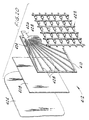
- Fig. 6 is an elevational view of the row of cells of the power generating system of Fig. 1 with opposite ends of the row of cells being urged together;
- Fig. 7 is an elevational view similar to Fig. 6 except the anodes have been consumed and the cells have been compressed;
- Fig. 8 is a schematic diagram of an alternative embodiment of an electrochemical power generating system of the present invention;
- Fig. 9 is a flow chart showing operation of the microprocessor of the power generating system of Fig. 8;
- Fig. 10 is a battery power versus time chart of the metal-air cell battery of the power generating system of Fig. 8 as electrolyte is pulsed through the cells;
- Fig. 11 is a cell temperature versus time chart of a metal-air cell of the power generating system of Fig. 8 as electrolyte is pulsed through the cell;
- Fig. 12 is a schematic diagram of the power system in a deactivated position;
- Fig. 13 is a schematic diagram of the power system during warm-up, immediately after being activated;
- Fig. 14 is a schematic diagram of the power system during normal operation;
- Fig. 15 is a schematic diagram of the power system during initial shut-down, immediately after being deactivated;
- Fig. 16 is a cross-sectional view of an alternative embodiment of a metal-air cell similar to the cell of Fig. 3 except the cell of Fig. 16 has two cathodes;
- Fig. 17 is a partial front elevational view of an alternative embodiment of a metal-air cell having an openable top;
- Fig. 18 is a section view taken along line 18-18 of Fig. 17;
- Fig. 19 is a top plan view of the metal-air cell of Fig. 17;
- Fig. 20 is an exploded perspective view of a cathode and wall of the pouch of the metal-air cell of Fig. 17; and
- Fig. 21 is a cross-sectional view similar to the view of Fig. 16 of an alternative embodiment of a metal-air cell.
-
- Corresponding reference characters indicate corresponding parts throughout the several views of the drawings.
- Referring to Figs. 1-3, an electrochemical power generating system of the present invention, generally indicated at 20, is shown to have a base unit, constituting a first portion, generally indicated at 22, and a replaceable fuel unit, constituting a second portion, generally indicated at 24. The
base unit 22 includes ahousing 26, anelectrolyte pump 28 within thehousing 26, and acontroller 30, constituting means for controlling operation of thepump 28. Thefuel unit 24 comprises ahousing 32 and a row of metal-air cells 34 electrically interconnected withinhousing 32. Eachcell 34 includes aflexible pouch 36, ametal anode 38 withinpouch 36, anair cathode 40, andspacers 42 for preventinganode 38 from contactingcathode 40.Pouch 36 has anelectrolyte inlet port 44 and anelectrolyte discharge port 46 for passage of electrolyte throughpouch 36 and betweenanode 38 andcathode 40. Asupply manifold 48 is withinhousing 32 for delivering electrolyte to thecells 34. The manifold 48 has anintake port 50 and a plurality ofdischarge ports 52. Thedischarge ports 52 are in fluid communication with theinlet ports 44 of thecells 34 via a plurality offlexible fluid lines 54 so that electrolyte flowing throughmanifold 48 is directed through theinlet ports 44 of thecells 34. Also withinhousing 32 is adischarge manifold 56 having a plurality ofintake ports 58 and adischarge port 60. A plurality offlexible fluid lines 62connect discharge ports 46 ofcells 34 tointake ports 58 ofdischarge manifold 56. Aconduit 64 connectsdischarge port 60 ofdischarge manifold 56 to anelectrolyte reservoir 66 positioned belowsupply manifold 48. Electrolyte flows fromcells 34, throughdischarge manifold 56, and then intoreservoir 66. - As shown in Fig. 1, a
conduit 68 connectsreservoir 66 to a heat exchanger 70 (preferably a fin and tube type heat exchanger) withinhousing 26.Pump 28 is connected toheat exchanger 70 via a conduit 71 and tointake port 50 ofsupply manifold 48 via aconduit 72. Thus,reservoir 66 andintake port 50 ofmanifold 48 are operatively connectable with theelectrolyte pump 28 for fluid communication therewith so thatpump 28 is able to draw electrolyte fromreservoir 66 and force it intomanifold 48. The electrolyte flows throughcells 34 and electrochemically couplesanodes 38 andrespective cathodes 40. The flowing electrolyte also flushes reaction products fromcells 34. Hydrogen gas generated by the reaction incells 34 is carried to dischargemanifold 56 by the electrolyte flowing throughcells 34. The hydrogen gas bubbles out of the electrolyte indischarge manifold 56 and is vented through a vent hole 67 inmanifold 56. Preferably,reservoir 66 is releasably connected toconduit 68 andconduit 72 is releasably connected tointake port 50 with quick-releasefluid line connectors Connectors fuel unit 24 tobase unit 22 so thatfuel unit 24 can be quickly attached to and detached frombase unit 22. Whenanodes 38 are consumed,fuel unit 24 can be detached quickly frombase unit 22 and replaced with a new fuel unit. Thus,power generating system 20 can be rapidly refueled, thereby minimizing down time. The usedfuel unit 24 can then be refueled or reclaimed. - As shown in Figs. 3 and 4,
cathode 40 has asubstrate 78 and acurrent collector 80 attached tosubstrate 78.Substrate 78 has anouter face 82 and aninner face 84.Substrate 78 is a sheet material (such as POREX® available from Porex Technology Corp. of Georgia) formed with or embedded with an activated carbonaceous material and is air-permeable and electrolyte-impermeable.Current collector 80 is a thin layer of electrically conductive material, such as nickel, silver, or stainless steel, formed on one of the faces ofsubstrate 78. Preferably,current collector 80 comprises a printed circuit on one of the faces ofsubstrate 78 in a pattern having a dendritic web extending from acommon conductor 86. The printed circuit may be formed onsubstrate 78, for example, by chemical etching, photo screening, or hot-foil stamping. -
Pouch 36 is flexible and compressible and has first and secondopposed walls 88 and 90, preferably formed of a polymeric material, such as polyethylene. The first wall 88 has awindow opening 92 with the margins ofsubstrate 78 permanently sealed to first wall 88 all aroundwindow opening 92. It is to be understood thatwindow 92 may be a specially treated portion of wall 88. In either case, only the window area is active and functions as a cathode. The exposed region ofsubstrate 78, i.e., the portion ofsubstrate 78 encompassed bywindow opening 92, is the portion ofsubstrate 78 which performs the cathodic function. Preferably, the margins ofsubstrate 78 are bonded to first wall 88 by an appropriate adhesive. Alternatively,substrate 78 could be secured to first wall 88 by heat sealing. Preferably, the carbonaceous material is deposited only in the interior region ofsubstrate 78 with the margins ofsubstrate 78 being relatively free of such material. Having no (or little) carbonaceous material at the margins ofsubstrate 78 enhances securement ofsubstrate 78 to first wall 88.Substrate 78 may also be formed of fibrillated polyolefin having a sufficient amount of carbonaceous material in the interior region to provide the desired electrolytic reactions and having a reduced amount of carbonaceous material (or none at all) at the margins to enhance securement to first wall 88. The ratio of carbonaceous material to fibrillated polyolefin may increase gradually from the edges ofsubstrate 78 to the center or may increase in an abrupt step. Alternatively, or additionally, the margins ofsubstrate 78 may be impregnated with a substance (such as polyethylene in solution) which promotes bonding to first wall 88. - Referring to Figs. 3 and 5,
anode 38 is a generally flat plate of aluminum, aluminum alloy, or other suitable metal such as magnesium or zinc, having a first face, constituting areaction face 94, and asecond face 96. The reaction face 94 opposes theinner face 84 of thecathode 40. An electrically conductive raiseddendritic pattern 98 is onsecond face 96 and extends from acommon conductor 100. Thedendritic pattern 98 ofanode 38 comprises a tapering main stem 98a that starts at thecommon terminal conductor 100 and extends substantially across thesecond face 96 and a plurality of tapering branches 98b extending from main stem 98a. During operation ofpower generating system 20,anode 38 is consumed from itsreaction face 94 toward itssecond face 96. If the anode is not consumed uniformly along the reaction face or if the thickness of the anode is not uniform (i.e., if there are thin spots), breaks or openings can form in the anode before it is substantially consumed. These breaks can isolate portions of the anode from the conductor, resulting in a partial or total reduction of energy output from the cell. To prevent isolation of these portions from the conductor, thedendritic pattern 98 protrudes fromsecond face 96. Even if breaks or openings form inanode 38,dendritic pattern 98 keeps all portions ofanode 38 in electrical contact withconductor 100. Thus,pattern 98 provides structural integrity and electrical communication acrossanode 38 toconductor 100 as the metal inanode 38 is consumed. Preferably,anode 38, includingdendritic pattern 98, is formed from a single homogeneous piece of metal. -
Spacers 42 are positioned betweencathode 40 and thereaction face 94 ofanode 38 to physically isolateanode 38 fromcathode 40 by a predetermined spacing, typically on the order of about 3mm (120 mils).Spacers 42 may be nubs or bosses integral withsubstrate 78 and projecting from theinner face 84 ofsubstrate 78. Alternatively, anode-cathode spacing may be maintained by a non-conducting lattice of criss-crossing members as described below with reference to Fig. 20. - Referring to Figs. 6 and 7, the entire row of
cells 34 is preferably surrounded by a resilient harness havingbanding straps 102 and tension springs 104 (only one of which is shown). Thestraps 102 extend around opposite ends of the row ofcells 34 and are connected together bysprings 104. Although not shown, it is to be understood that the harness is electrically insulated fromterminal connectors Springs 104 are tensioned to urge opposite ends of the row ofcells 34 toward each other. Sincepouch 36 of eachcell 34 is flexible, the harness urges theanode 38 andcathode 40 of eachcell 34 toward each other with spacers 42 (see Fig. 3) of each cell being squeezed by thereaction face 94 ofanode 38 and theinner face 84 ofcathode 40. Fig. 6 shows the row ofcells 34 beforeanodes 38 have begun to be consumed and, therefore,cells 34 and their respective anodes are relatively thick. Fig. 7 shows the row ofcells 34 with most of each anode being consumed and, therefore,cells 34 and their respective anodes are relatively thin and the row ofcells 34 is compressed. Preferably,fluid lines cells 34. Alternatively, the intake and discharge manifolds could each have a bellows-type configuration which contracts as the row ofcells 34 contracts. Sinceanode 38 andcathode 40 are being squeezed againstspacer 42, the distance between theinner face 84 ofcathode 40 and thereaction face 94 ofanode 38 remains substantially constant (i.e., the same as the thickness of spacers 42) during consumption ofanode 38. Since the distance betweencathode 40 and reaction face 94 remains substantially constant, consumption ofanode 40 does not result in a decrease in voltage and power output of the cell. Also, this distance remains substantially constant during consumption ofanode 38 regardless of the initial thickness ofanode 38. With thicker anodes, the metal-air cell battery is operable for longer periods between refueling and without an appreciable reduction in power output. - Although harness 103 constitutes the preferred means for urging the anode and cathode of each cell toward each other, it is to be understood that other means may be employed without departing from the scope of this invention. Examples of other ways of urging opposite ends of the row of
cells 34 together include: tensioned elastomeric bands placed around the row of cells; interacting wedges at ends of the row of cells which produce a compressive force against the ends; two rigid end plates engaging opposite ends of the row of cells with the end plates being urged toward each other by tensioned springs; compression springs at one end of the row of cells which urge the one end toward the other end; an inflatable bag at one end of the row of cells which, upon inflation, urges the one end toward the other end; or a hydraulic cylinder at one end of the row of cells which, upon being pressurized, urges the one end toward the other end. - Referring again to Fig. 1, the
base unit 22 further includes anair pump 108, constituting a depolarization air system, for forcing slightly compressed air across the cathodes. A plurality of inter-cell spacers or separators 106 (also shown in Figs. 2, 3 and 6), preferably formed of a synthetic resin, are interposed betweenadjacent cells 34 to provide air spaces adjacent the cathodes so that the depolarizing air can circulate around the cells and to the cathodes. The circulation of air aroundcells 34 also helps to cool the cells. The thickness of thespacers 106 betweencells 34 may vary so that the sizes of the spaces between adjacent cells varies to achieve variable cooling of the cells. For example the inter-cell spacing can decrease from one end of the row of cells to the other, or the inter-cell spacing can decrease from the center of the row of cells toward the ends of the row. The thickness ofspacers 106 is selected generally to achieve equalization of the temperatures of thecells 34 in the row of cells. - A cooling
fan 110 is withinhousing 26 for forcing cooling air across the fins ofheat exchanger 70 to cool electrolyte withinheat exchanger 70. A lead-acid battery 112, or other suitable secondary battery, operatespump 28,controller 30, and pump 108 andfan 110 during start-up of the metal-air cell battery. - Referring to Figs. 1, 4 and 6, the
conductors 86 ofcathodes 40 are directly connected to theconductors 100 ofanodes 38 of adjacent cells thereby connectingcells 34 in series to each other. Battery stackend cathode conductor 86 is connected to negative contact pad 115a via an electric cable (not shown). Battery stackend anode conductor 100 is connected to positive contact pad 115b via electric cable 113b. Positive and negative electrical contact pads 115a and 115b (see Fig. 2) extend through aside wall 114 ofhousing 32. The contact pads 115a and 115b are interengageable with two like polarity contact pads (not shown) extending through aside wall 116 ofhousing 26 for electrically connecting the metal-air cell battery to an external load and to lead-acid battery 112.Base unit 22 further includes positive and negative load engageable terminals (not shown) through asecond side wall 118 ofhousing 26 and suitable conductors (not shown) for providing electrical energy to the terminals. - Another embodiment of an electrochemical power generating system of the present invention, generally indicated at 220, is shown schematically in Fig. 8.
Power generating system 220 comprises a fluid system, a gas system, and an electrical system. The fluid system includes asump 224, anelectrolyte filter 226, a heat exchanger 228, and a reversible-flow pump 230 for moving electrolyte through a plurality of metal-air cells, generally indicated at 222. Electrolyte flows fromcells 222 through a conduit 232 and tosump 224 which includes a plurality ofbaffles 224a for collection of reaction products discharged from the cells. Electrolyte fromsump 224 flows through a conduit 234 to filter 226, which filters reactants, generated incells 222, from the electrolyte. Electrolyte moves fromfilter 226 to heat exchanger 228 via aconduit 236. Heat exchanger 228 is preferably a fin and tube type heat exchanger and includes a coolingfan 229 for moving air across the fins for cooling the electrolyte when the electrolyte exceeds a predetermined temperature. Heat exchanger 228 is in fluid communication withpump 230 via aconduit 238. Anelectrolyte reservoir 240 is in fluid communication withconduit 238 via aconduit 242. Electrolyte fromreservoir 240 is introduced into the circulatory system only if and when the electrolyte insump 224 falls below a minimum acceptable level. Thereservoir 240 maintains proper electrolyte level incells 222. Electrolyte frompump 230 flows through aconduit 244 tocells 222 via aconcentration sensor 250. The electrolyte may be an aqueous solution of potassium hydroxide (KOH), sodium hydroxide (NaOH), sodium chloride (NaCl), or any other suitable electrolyte. The electrolyte insump 224 maybe seeded with micro-crystals of the anticipated reaction products, such as Al(OH)3 in aluminum air cells where the electrolyte is KOH, to cause the reaction products to precipitate out of the electrolyte solution and facilitate the trapping of these products insump 224. -
Power generating system 220 also includes anelectrolyte concentrate reservoir 246, a solenoid-actuatedmetering valve 248, and anelectrolyte concentration sensor 250.Concentrate reservoir 246 is in communication withconduit 244 via twoconduits valve 248.Sensor 250 senses concentration of electrolyte and may be, for example, a conductivity sensor which measures the conductivity of the electrolyte solution to gauge the electrolyte concentration. Alternatively,sensor 250 may be a pH sensor which measures the pH of the electrolyte solution to gauge the electrolyte concentration. When the concentration of the electrolyte falls below a predetermined value,valve 248 meters concentrated electrolyte fromreservoir 246 toconduit 244. The concentrated electrolyte increases the concentration of electrolyte transported tocells 222. Thus, weak electrolyte is automatically replenished. - An
air pump 256 forces depolarizing air tocells 222. The circulating air is passed through afilter 257 to remove contaminants, particularly carbon particles, that might contaminate the system. The electrochemical reaction in the cells produces hydrogen gas which is vented from the cells by aconduit 258.Conduit 258 communicates with acatalytic bed 260. Air and byproduct gasses, such as hydrogen, fromcells 222 are forced to pass throughcatalytic bed 260 where the hydrogen is recombined with atmospheric oxygen to form water. The water drains fromcatalytic bed 260 tosump 224 through aconduit 262, where it replenishes moisture lost from the electrolyte during operation ofcells 222. Alternatively, or in addition, a vent can be provided to allow H2 gas to escape, with or without the assistance ofair pump 256 orfan 229. -
Power generating system 220 has acontroller 264, preferably in the form of a microprocessor, for controllingpump 230, coolingfan 229,metering valve 248, andair pump 256. A lead-acid battery 266 or any suitable supplemental battery operatescontroller 264 and pump 230 during start-up ofpower generating system 220. During operation ofpower generating system 220, i.e., when power is being supplied to a load,battery 266 serves as an accumulator for accommodating power surges demanded by the load above the normal output limits ofcells 222.Battery 266 is normally connected in parallel with the row ofcells 222 via controller-controlled switches 267 described in more detail below. Lead-acid battery 266 provides power to activate generatingsystem 220, and to complete shut-down operations after amaster switch 269 is opened. Avoltmeter 261 andammeter 263 are provided to give the operator an indication of the system voltage and the amount of current being drawn aspower generating system 220 is loaded.Power generating system 220 could also be provided with other indicators, such as temperature indicators, electrolyte fluid level indicators, and a fuel indicator indicating the thickness of the anodes or the operating time remaining. - Referring to Fig. 8 and the flow chart of Fig. 9, the operation of
pump 230 andfan 229 bycontroller 264 will be described.Controller 264 enablescells 222 to rapidly reach full power even when the electrolyte is initially cold. Afirst temperature sensor 268 senses electrolyte temperature in the circulatory system. Asecond temperature sensor 270 is in at least one of the cells for measuring the temperature of electrolyte in the cells. Initially, no electrolyte is in the cells ofbattery 222. When thepower generating system 220 is turned on,controller 264, atstep 272, compares the system temperature, as measured byfirst sensor 268, with a predetermined temperature TS. If the system temperature does not exceed temperature TS,controller 264 activates pump 230 for a brief predetermined duration D1 atstep 274. This brief activation causes a charge (volume) of electrolyte to be pumped into the cells. The electrolyte charge is held statically (or near statically) within the cells so that it quickly absorbs heat from the electrochemical reaction taking place between the cathodes and anodes. Instep 276, after the charge is pumped into the cells,controller 264 compares the electrolyte temperature in the cells, as measured bysecond sensor 270, with a predetermined temperature T1. If the cell temperature does not exceed temperature T1,controller 264 reexecutes step 274, and repeatedly does so until the cell temperature exceeds temperature T1. When temperature T1 is exceeded,controller 264 returns to start atstep 278. If the system temperature does not exceed temperature TS,controller 264 will repeat steps 272-278. As steps 272-278 are repeated, a fresh charge of electrolyte is pumped into the cells and the old charge (i.e., the one heated during the previous cycle) is forced intosump 224.Controller 264 will repeat steps 272-278, incrementally elevating the temperature in the fluid system (including reservoir 240), until the system temperature exceeds temperature TS. By pulsing charges of electrolyte into the cells and allowing them to remain static until they reach an optimal temperature,cells 222 can operate at near full power without waiting for all the electrolyte in the system to heat up. Also, sincecells 222 quickly operate at near full power, the system electrolyte is heated at a much faster rate than could be accomplished with a continuous flow system. Graphs representing battery power vs. time and cell temperature vs. time during electrolyte pulsing are shown in Figs. 10 and 11. - When
controller 264 determines that the system temperature exceeds temperature TS, pump 230 is operated for continuous flow instep 280. Instep 282,controller 264 compares the electrolyte temperature in the cells, as measured bysecond sensor 270, with a predetermined temperature T3. If the cell temperature exceeds temperature T3,controller 264, instep 284, energizes coolingfan 229 to cool electrolyte passing through heat exchanger 228. If instep 282, the cell temperature does not exceed temperature T3,controller 264 compares the cell temperature with a predetermined temperature T2 (which is less than temperature T3) instep 286. If the cell temperature is lower than temperature T2,controller 264 signals a relay for deactivatingcooling fan 229 instep 288.Controller 264 then returns to start instep 290. Temperatures T2 and T3 are selected to maintain a stable temperature for the electrolyte solution within the optimum operating range of the system. Thus,controller 264 selectively energizesfan 229 for controlling cooling of the electrolyte. -
Controller 264controls metering valve 248 in response toelectrolyte concentration sensor 250, openingvalve 248 to release concentrated electrolyte intoconduit 244 to boost the concentration of electrolyte whensensor 250 detects that the concentration has fallen below a predetermined level.Controller 264 may further controlpump 230 by varying the pulse duration D1 as a function of electrolyte temperature. For example,controller 264 could cause duration D1 to increase as the system temperature increases. Also,controller 264 could control pump 230 as a function of some operating condition ofcells 222 other than electrolyte temperature. For example, pump 230 may be operated as a function of a voltage generated bycells 222. - As noted above,
controller 264 also controls operation ofpower generating system 220 during shut-down. When amaster switch 269 is manually set so thatsystem 220 is deactivated,controller 264 initially connects lead-acid battery 266 across the row ofcells 222, applying reverse polarity voltage to inhibit electron flow and thus help protect the anodes incells 222 from further electrochemical depletion. However, ifsystem 220 is not turned on again within a predetermined duration D2 (e.g., one hour), then a timing switch withincontroller 264 disconnects the lead-acid battery 266 fromcells 222 and sends a signal to causepump 230 to operate in reverse pump mode to draw electrolyte from the cells and force it back through heat exchanger 228 and intosump 224. After a predetermined duration, or whencells 222 are substantially empty,controller 264 deactivatespump 230. - The start up and shut down operations of
system 220 are illustrated in Figs. 12-15. In Fig. 12,system 220 is shown in a deactivated state, with no power being supplied to the load. In Fig. 13 the system is shown immediately afterswitch 269 has been moved to the position shown thereby causing current from lead-acid battery 266 to be provided tocontroller 264, and causing a solenoid actuatedmaster contactor 271 to connectbattery 266 to the load,switch 273, ganged to switch 269 thereby connects afirst plurality 275 of cells 222 (constituting a first part of the row of cells 222) to asecond plurality 277 of cells 222 (constituting a second part of the row of cells 222) in series. In the position shown, switch 269 also energizes asolenoid 279 thereby to reposition twoswitches switch 281 causesbattery 266 to be connected to the row ofcells 222 in series, and the repositioning ofswitch 283 causesbattery 266 and the row ofcells 222 to be connected through a current-limitingresistor 285 to ground. Thus,battery 266 provides a current, limited byresistor 285, to heatcells 222 and to depassivate the anodes, breaking up films (such as an oxidation layer) that may form on the anodes. Whencells 222 have been warmed, a normally closedthermal switch 287 opens, de-energizingsolenoid 279 andrepositioning switches switch 281 is repositioned, it connects the negative terminal of the row ofcells 222 to ground andswitch 283 connects the positive terminal of the row of cells to the load, in parallel withbattery 266.Battery 266 and the row of cells can thus provide current to the load in parallel. However, the higher voltage output of the row of cells at maximum rated current levels exceeds the voltage ofbattery 266, and thus the row of cells usually provides all of the power output and also keepsbattery 266 charged. - When the
system 220 is shut down by movingswitch 269 to the position shown in Fig. 15,master contactor 271 is de-energized, disconnecting the output from the load. Switch 269 also initiates operation of a corrosion inhibittimer 289 which temporarily closes two normallyopen switches 291 and 293, and repositionsswitch 273 separatingfirst plurality 275 of cells andsecond plurality 277. Closing switch 291 connectsbattery 266 through a current-limitingresistor 295 to the positive terminal of thefirst plurality 275 of cells, the negative terminal of which is connected to ground.Closing switch 293 connects the negative terminal of thesecond plurality 277 of cells through a current-limiting resistor 297 to ground, the positive terminal of which is already connected tobattery 266. Withswitches 291 and 293 closed,battery 266 provides positive bias voltage to protect the anodes incells 222 from consumption. After a predetermined period, corrosion inhibittimer 289 sends a signal tocontroller 264 to openswitches 291 and 293.Controller 264 then activatespump 230 in reverse mode to drain the electrolyte intosump 224, to prevent further consumption of the anodes. - Another embodiment of a metal-air cell, generally indicated at 334, is shown in Fig. 16.
Cell 334 includes a flexible pouch 336, ametal anode 338 within pouch 336, twoair cathodes 340, and twospacers 342 for preventingcathodes 340 from contactinganode 338. The primary difference betweencell 334 andcell 34 is thatcell 334 has two cathodes. Eachcathode 340 has asubstrate 378 and acurrent collector 380. Eachsubstrate 378 is air-permeable and electrolyte-impermeable. Anode 336 has afirst reaction face 394a opposing the inner face of one cathode and asecond reaction face 394b opposing the inner face of the other cathode. Preferably, reaction faces 394a and 394b are both generally planar to provide flat reaction surfaces. Pouch 336 has first and secondopposed walls 388 and 390, having first andsecond windows 392a and 392b, respectively.Spacers 342 are electrolyte-resistant non-conductive fibrous sheets formed of randomly oriented fibers and preferably have a thickness of approximately 3mm. Alternatively,spacers 342 may be knitted, woven, felted, etc., and may be formed of nylon, polyamide fusing web, polyester, etc. Having cathodes opposing both faces ofanode 338 doubles the reaction surface area and effectively doubles the power output ofcell 334. - Another embodiment of a metal-air cell, generally indicated at 400, is shown in Figs. 17-20.
Cell 400 comprises aflexible pouch 402 having first and second walls (or panels) 404 and 406, the perimeters of which are sealed together to form a pouch having an open top. First andsecond panels second films second panels current collectors films Panels films current collectors Panel 404,film 408, andcurrent collector 410 constitute a first air cathode 412 having an inner face 414;panel 406,film 409, andcurrent collector 411 constitute a second air cathode 413 having an inner face 415. Withinpouch 402 is ametal anode 416, having first and second reaction faces 418 and 420, andspacers first face 418 ofanode 416 opposes inner face 414 of cathode 412 and the second face 420 opposes inner face 415 of cathode 413.Spacer 422 is between inner face 414 andfirst face 418 andspacer 423 is between inner face 415 and second face 420 for preventinganode 416 from contacting cathodes 412 and 413. Eachspacer rectangular frame 424 surrounding one of thefilms terminal connector 426 adjacent a corner offrame 424, and a plurality ofconductive filaments 428 each extending fromelectrical connector 426 to frame 424. As an alternative to the filaments, each current collector may have a grid pattern or any other suitable pattern.Connector 426 extends throughpouch 402 at the sealed perimeter. -
Pouch 402 includes aninlet 430 and anoutlet 432 to allow electrolyte solution to be circulated throughcell 400.Inlet 430 is preferably located generally adjacent the bottom ofpouch 402 at the sealed perimeter, andoutlet 432 is preferably located generally adjacent the top ofpouch 402 at the sealed perimeter to cause thorough circulation of the electrolyte solution frominlet 430, up and acrosscell 400, tooutlet 432. Elongate, resilient sealingbeads panels beads pouch 402 and are engageable with each other to seal the top of the pouch. Anelongate clamp 442 fits overbeads seal pouch 402. An electricalterminal connector 444 extends upwardly fromanode 416 and between sealingbeads slot 446 at one end ofclamp 442. Sealingbeads connector 444. Preferably, anend cap 447 is placed over the slotted end ofclamp 442 to secure the clamp on the pouch.Clamp 442 is easily removed frompouch 402 to allow opening of the pouch to remove the remainder of the spent anode, and install a replacement anode.Clamp 442 and sealingbeads - Although
cell 400 has been described as having two cathodes, it is to be understood that activated carbonaceous material may coat or be embedded in the entire inner surface of the pouch and a current collector may blanket the entire inner surface of the pouch so that the pouch, carbonaceous material and current collector form an active cathode which envelops the anode. - Another embodiment of a metal-air cell, generally indicated at 534, is shown in Fig. 21.
Cell 534 includes a flexible pouch, generally indicated at 536, ametal anode 538 withinpouch 536, two air cathodes, generally indicated at 540, and twospacers 542 for preventingcathodes 540 from contactinganode 538.Cell 534 is similar tocell 334 shown in Fig. 16 in that both have two cathodes.Pouch 536 comprises twopanels 588 and 590, the perimeters of which are joined together to form a pouch having an open top, similar topouch 402 shown in Figs. 17-20.Panels 588 and 590 are air-permeable and electrolyte-impermeable and may be of a microporous metal foil, such as stainless steel, having pores sufficiently large to permit air to pass therethrough and sufficiently small to prevent electrolyte from passing therethrough. A suitable material is microporous stainless steel available from Hruden Laboratories of Woodinville, Washington.Films 578 of cathodic material, such as an activated carbonaceous material, are deposited on the inner surfaces ofpanels 588 and 590.Panels 588 and 590 constitute substrates forfilms 578. Preferably,current collectors 580 are in contact with the inner surface of eachfilm 578 and are electrically isolated from thefoil panels Panels 588 and 590,films 578, andcurrent collectors 580 constituteair cathodes 540.Anode 536 has first and second reaction faces 594a, 594b opposing the inner faces ofcathodes 540.Spacers 542 are preferably the same asspacers - In view of the above, it will be seen that the several objects of the invention are achieved and other advantageous results attained.
- As various changes could be made in the above constructions without departing from the scope of the invention, it is intended that all matter contained in the above description or shown in the accompanying drawings shall be interpreted as illustrative and not in a limiting sense.
Claims (6)
- A power generating system comprising a metal-air cell (34; 222; 334; 400; 534), the metal-air cell (34; 222; 334; 400; 534) including:a flexible, collapsible pouch (36; 402; 536) having first and second opposed walls (88, 90; 388, 390; 404, 406; 588, 590), at least one of which includes an air-permeable and electrolyte-impermeable air cathode (40; 412, 413; 540);a metal anode (38; 416; 536) within the pouch (36; 402; 536) and surrounded thereby and having a first reaction face (94; 394a, 394b; 418, 420; 594a, 594b) opposing the cathode (40; 412, 413; 540);a spacer (42; 342; 422, 423; 542) between the cathode (40; 412; 413; 540) and the reaction face (94; 394a, 394b; 418, 420; 594a, 594b) of the anode (38; 416; 536) for preventing the anode (38; 416; 536) from contacting the cathode (40; 412, 413; 540), the spacer (42; 342; 422, 423; 542) separating the anode (38; 416; 536) and the cathode (40; 412, 413; 540) for maintaining a substantially constant spacing between the anode (38; 416; 536) and the cathode (40; 412, 413; 540) as the anode (38; 416; 536) is consumed durinc operation;the pouch (36; 402; 536) comprising two panels (88, 90; 388, 390; 404, 406; 588, 590) of a flexible material joined together along their edges to form a flexible pouch (36; 402; 536).
- A power generating system according to claim 1, wherein the metal-air cell (34; 222; 334; 400; 534) comprises one of a row of similar metal-air cells (34; 222; 334; 400; 534), the system further comprising means (102, 104) for urging opposite ends of the row of collapsible cells (34; 222; 334; 400; 534) toward each other thereby to urge the anode (38; 416; 536) and cathode (40; 412, 413; 540) of each cell (34; 222; 334; 400; 534) toward each other so that the spacing between the inner face (84; 414, 415) of the cathode (40; 412, 413; 540) and the reaction face (94; 394a, 394b; 418, 420; 594a, 594b) of the anode (38; 416; 536) of each cell (34; 222; 334; 400; 534) remains substantially constant during consumption of the anode (38; 416; 536).
- A power generation system according to claim 1 or claim 2, further comprising:an inlet (44; 430) and an outlet (46; 432) in the pouch (36; 402; 536) to allow electrolyte solution to be circulated through the cell (34; 222; 334; 400; 534), between the anode (38; 416; 536) and the cathode (40; 412, 413; 540);a circulatory system for delivering electrolyte solution to the inlet (44; 430) of the cell (34; 222; 334; 400; 534) and removing electrolyte solution from the outlet (46; 432) of the cell (34; 222; 334; 400; 534), the circulatory system including a pump (28; 230) and a heat exchanger (70; 228) through which the electrolyte solution circulates;a cooling fan (110; 229) for forcing cooling air over the heat exchanger (70; 228);a sensor (268) for monitoring the temperature of the electrolyte solution circulating in the circulatory system, and a controller (30; 264) for turning on the fan (110; 229) when the temperature of the electrolyte solution exceeds a temperature T3, and for turning off the fan (110; 229) when the temperature of the electrolyte solution is less than a temperature T2, the temperature T3 being greater than the temperature T2.
- A power generating system according to any one of claims 1 to 3, further comprising:an inlet (44; 430) and an outlet (46; 432) in the pouch (36; 402; 536) to allow an electrolyte solution to be circulated through the cell (34; 222; 334; 400; 534), between the anode (38; 416; 536) and the cathode (40; 412, 413; 540);a circulatory system for delivering electrolyte solution to the inlet (44; 430) of the cell (34; 222; 334; 400; 534) and removing electrolyte solution from the outlet (46; 432) of the cell (34; 222; 334; 400; 534), the circulatory system including a pump (28; 230);a supplemental battery (112; 266) for connection in parallel with the cell (34; 222; 334; 400; 534), and sized to provide operating power for the system and supplementary power to the system during periods of peak current demand by an external load; anda controller (30; 264) for temporarily connecting the supplemental battery (112; 266) in series with the cell (34; 222; 334; 400; 534) when the power generating system is turned on to facilitate start up of the power generating system.
- A power generating system according to any one of claims 1 to 4, wherein the metal-air cell (34; 222; 334; 400; 534) comprises one of a stack of similar metal-air cells (34; 222; 334; 400; 534), the system comprising a first unit (24) including the stack of metal-air cells (34; 222; 334; 400; 534), and a second unit (22), releasably connectable to the first unit (24), each metal-air cell (34; 222; 334; 400; 534) having an inlet (44; 430) and an outlet (46; 432) in the pouch (36; 402; 536) to allow an electrolyte solution to be circulated through the cell (34; 222; 334; 400; 534) between the anode (38; 416; 536) and cathode (40; 412, 413; 540), the second unit (22) comprising a circulatory system for delivering electrolyte to the inlets of the cells (34; 222; 334; 400; 534) and removing electrolyte from the outlets of the cells (34; 222; 334; 400; 534), the circulatory system including a pump (28; 230), and a controller (30; 264) for controlling the circulatory system.
- A power generating system according to claim 5, wherein the power generating system includes a supplemental battery (112; 266), and wherein the controller (30; 264) is adapted for connecting the supplemental battery (112; 266) across the stack with reverse polarity for a predetermined time when the power generating system is turned off to inhibit electron flow and so preserve the anodes (38; 416; 536) in the cells (34; 222; 334; 400; 534).
Applications Claiming Priority (5)
| Application Number | Priority Date | Filing Date | Title |
|---|---|---|---|
| US07/955,583 US5415949A (en) | 1992-10-02 | 1992-10-02 | Metal-air cell and power system using metal-air cells |
| US08/081,662 US5439758A (en) | 1992-10-02 | 1993-06-23 | Electrochemical power generating system |
| US81662 | 1993-06-23 | ||
| PCT/US1993/009188 WO1994008358A1 (en) | 1992-10-02 | 1993-09-27 | Electrochemical power generating system |
| US955583 | 1997-10-22 |
Publications (3)
| Publication Number | Publication Date |
|---|---|
| EP0665986A1 EP0665986A1 (en) | 1995-08-09 |
| EP0665986A4 EP0665986A4 (en) | 1999-05-06 |
| EP0665986B1 true EP0665986B1 (en) | 2001-08-01 |
Family
ID=26765810
Family Applications (1)
| Application Number | Title | Priority Date | Filing Date |
|---|---|---|---|
| EP93922413A Expired - Lifetime EP0665986B1 (en) | 1992-10-02 | 1993-09-27 | Electrochemical power generating system |
Country Status (9)
| Country | Link |
|---|---|
| US (2) | US5439758A (en) |
| EP (1) | EP0665986B1 (en) |
| JP (1) | JPH08505730A (en) |
| KR (1) | KR950703802A (en) |
| AT (1) | ATE203853T1 (en) |
| AU (1) | AU675460B2 (en) |
| CA (1) | CA2146158A1 (en) |
| DE (1) | DE69330527T2 (en) |
| WO (1) | WO1994008358A1 (en) |
Families Citing this family (94)
| Publication number | Priority date | Publication date | Assignee | Title |
|---|---|---|---|---|
| US5439758A (en) * | 1992-10-02 | 1995-08-08 | Voltek, Inc. | Electrochemical power generating system |
| US5418080A (en) * | 1994-07-01 | 1995-05-23 | Electric Fuel (E.F.L.) Ltd. | Mechanically rechargeable, electrochemical metal-air battery |
| US5650241A (en) * | 1994-09-09 | 1997-07-22 | Mcgee; Richard L. | Metal-air cell battery |
| US5716726A (en) * | 1994-12-22 | 1998-02-10 | Dreisbach Electromotive, Inc. | Electrolyte starved metal-air battery |
| US6106962A (en) * | 1997-09-24 | 2000-08-22 | Aer Energy Resources Inc. | Air manager control using cell voltage as auto-reference |
| US6239508B1 (en) | 1997-10-06 | 2001-05-29 | Reveo, Inc. | Electrical power generation system having means for managing the discharging and recharging of metal fuel contained within a network of metal-air fuel cell battery subsystems |
| US6299997B1 (en) | 1997-10-06 | 2001-10-09 | Reveo, Inc. | Ionically-conductive belt structure for use in a metal-air fuel cell battery system and method of fabricating the same |
| US6558829B1 (en) | 1997-10-06 | 2003-05-06 | Reveo, Inc. | Appliance with refuelable and rechargeable metal-air fuel cell battery power supply unit integrated therein |
| US6348277B1 (en) | 1997-10-06 | 2002-02-19 | Reveo, Inc. | Method of and system for producing and supplying electrical power to an electrical power consuming device using a metal-air fuel cell battery (FCB) module and a supply of metal-fuel cards |
| US6306534B1 (en) | 1997-10-06 | 2001-10-23 | Reveo, Inc. | Metal-air fuel cell battery systems employing means for discharging and recharging metal-fuel cards |
| US6569555B1 (en) | 1997-10-06 | 2003-05-27 | Reveo, Inc. | Refuelable and rechargeable metal-air fuel cell battery power supply unit for integration into an appliance |
| US6335111B1 (en) | 1997-10-06 | 2002-01-01 | Reveo, Inc. | Metal-air fuel cell battery system employing a plurality of moving cathode structures for improved volumetric power density |
| US6641943B1 (en) | 1997-10-06 | 2003-11-04 | Reveo, Inc. | Metal-air fuel cell battery system having means for recording and reading operating parameters during discharging and recharging modes of operation |
| US6472093B2 (en) | 1997-10-06 | 2002-10-29 | Reveo, Inc. | Metal-air fuel cell battery systems having a metal-fuel card storage cartridge, insertable within a fuel cartridge insertion port, containing a supply of substantially planar discrete metal-fuel cards, and fuel card transport mechanisms therein |
| US6451463B1 (en) | 1997-10-06 | 2002-09-17 | Reveo, Inc. | Electro-chemical power generation systems employing arrays of electronically-controllable discharging and/or recharging cells within a unity support structure |
| US6296960B1 (en) | 1997-10-06 | 2001-10-02 | Reveo, Inc. | System and method for producing electrical power using metal-air fuel cell battery technology |
| US6287715B1 (en) | 1997-10-06 | 2001-09-11 | Reveo, Inc. | Metal-air fuel cell battery system having means for controlling discharging and recharging parameters for improved operating efficiency |
| US6228519B1 (en) | 1997-10-06 | 2001-05-08 | Reveo, Inc. | Metal-air fuel cell battery systems having mechanism for extending the path length of metal-fuel tape during discharging and recharging modes of operation |
| WO1999045607A1 (en) | 1998-03-03 | 1999-09-10 | Celltech Power, Llc | A carbon-oxygen electricity-generating unit |
| AR018815A1 (en) * | 1998-04-02 | 2001-12-12 | Procter & Gamble | BATTERY THAT HAS AN INCORPORATED CONTROLLER |
| US6660418B1 (en) | 1998-06-15 | 2003-12-09 | Aer Energy Resources, Inc. | Electrical device with removable enclosure for electrochemical cell |
| US6093500A (en) * | 1998-07-28 | 2000-07-25 | International Fuel Cells Corporation | Method and apparatus for operating a fuel cell system |
| EP1142055A1 (en) * | 1998-11-30 | 2001-10-10 | Electric Fuel Limited | Pressurized metal-air battery cells |
| EP1142054A1 (en) * | 1998-12-15 | 2001-10-10 | Electric Fuel Limited | Battery pack design for metal-air battery cells |
| US6299998B1 (en) | 1999-03-15 | 2001-10-09 | Reveo, Inc. | Movable anode fuel cell battery |
| US9397370B2 (en) | 1999-06-25 | 2016-07-19 | The Board Of Trustees Of The University Of Illinois | Single and multiple cell battery with built-in controller |
| US6653003B1 (en) | 1999-10-12 | 2003-11-25 | Reveo Inc. | Fuel cell support and electrical interconnector |
| RU2002130712A (en) * | 2000-04-18 | 2004-03-10 | Селлтек Пауэр, Инк. (Us) | Electrochemical device and methods of energy conversion |
| US6544679B1 (en) | 2000-04-19 | 2003-04-08 | Millennium Cell, Inc. | Electrochemical cell and assembly for same |
| US6558825B1 (en) | 2000-05-12 | 2003-05-06 | Reveo, Inc. | Fuel containment and recycling system |
| US6824915B1 (en) | 2000-06-12 | 2004-11-30 | The Gillette Company | Air managing systems and methods for gas depolarized power supplies utilizing a diaphragm |
| US6759159B1 (en) | 2000-06-14 | 2004-07-06 | The Gillette Company | Synthetic jet for admitting and expelling reactant air |
| US6824905B2 (en) * | 2001-01-15 | 2004-11-30 | Casio Computer Co., Ltd. | Power supply system and device driven by power supply system |
| AU2002309797A1 (en) | 2001-05-14 | 2002-11-25 | Reveo, Inc. | Metal air cell incorporating ionic isolation systems |
| WO2003001617A2 (en) * | 2001-06-25 | 2003-01-03 | Celltech Power, Inc. | Electrode layer arrangements in an electrochemical device |
| AU2002363943A1 (en) * | 2001-11-20 | 2003-06-10 | Celltech Power, Inc. | An electrochemical system and methods for control thereof |
| US7297170B2 (en) * | 2002-07-26 | 2007-11-20 | 3M Innovative Properties Company | Method of using abrasive product |
| US6833014B2 (en) * | 2002-07-26 | 2004-12-21 | 3M Innovative Properties Company | Abrasive product, method of making and using the same, and apparatus for making the same |
| US7044989B2 (en) * | 2002-07-26 | 2006-05-16 | 3M Innovative Properties Company | Abrasive product, method of making and using the same, and apparatus for making the same |
| AU2003291649A1 (en) * | 2002-10-23 | 2004-05-13 | Inventqjaya Sdn. Bhd. | System for convenient introduction and removal of electrolyte in mechanically rechargeable metal air cells |
| EP1429407A1 (en) * | 2002-12-11 | 2004-06-16 | SFC Smart Fuel Cell GmbH | Conception of production series |
| US7432011B2 (en) * | 2002-12-13 | 2008-10-07 | University Of South Florida | Actuated electrochemical power source |
| US7157171B2 (en) * | 2003-05-09 | 2007-01-02 | Nanotek Instruments, Inc. | Metal-air battery with programmed-timing activation |
| ITVI20030099A1 (en) * | 2003-05-16 | 2004-11-17 | Franco Stocchiero | METHOD FOR THE FORMATION OF LEAD-ACID BATTERIES ED |
| US7943270B2 (en) * | 2003-06-10 | 2011-05-17 | Celltech Power Llc | Electrochemical device configurations |
| US20060040167A1 (en) * | 2003-10-16 | 2006-02-23 | Celltech Power, Inc. | Components for electrochemical devices including multi-unit device arrangements |
| WO2004112175A2 (en) * | 2003-06-10 | 2004-12-23 | Celltech Power, Inc. | Oxidation facilitator |
| JP2007524209A (en) * | 2004-02-16 | 2007-08-23 | ミート カンパニー リミテッド | Foldable air battery |
| US7275019B2 (en) * | 2005-05-17 | 2007-09-25 | Dell Products L.P. | System and method for information handling system thermal diagnostics |
| US20070015021A1 (en) * | 2005-07-18 | 2007-01-18 | Yaron Shrim | Canless bi-cell |
| US20070245755A1 (en) * | 2006-04-24 | 2007-10-25 | Galvez-Ramos Antonio M | Air cooling system for parked automobiles |
| US9780394B2 (en) * | 2006-12-21 | 2017-10-03 | Arizona Board Of Regents For And On Behalf Of Arizona State University | Fuel cell with transport flow across gap |
| US20090017342A1 (en) * | 2006-12-21 | 2009-01-15 | Arizona Board Of Regents For And On Behalf Of Arizona State University The Brickyard | Fuel cell with switching electrodes |
| US8168337B2 (en) * | 2008-04-04 | 2012-05-01 | Arizona Board Of Regents For And On Behalf Of Arizona State University | Electrochemical cell, and particularly a metal fueled cell with non-parallel flow |
| US8309259B2 (en) | 2008-05-19 | 2012-11-13 | Arizona Board Of Regents For And On Behalf Of Arizona State University | Electrochemical cell, and particularly a cell with electrodeposited fuel |
| JP5353347B2 (en) * | 2009-03-19 | 2013-11-27 | トヨタ自動車株式会社 | Air battery |
| JP5446392B2 (en) * | 2009-04-01 | 2014-03-19 | トヨタ自動車株式会社 | Air battery |
| AU2010303211B2 (en) | 2009-10-08 | 2014-06-12 | Fluidic, Inc. | Rechargeable metal-air cell with flow management system |
| JP5050065B2 (en) * | 2010-02-05 | 2012-10-17 | 株式会社日立製作所 | Metal-air secondary battery |
| US8659268B2 (en) | 2010-06-24 | 2014-02-25 | Fluidic, Inc. | Electrochemical cell with stepped scaffold fuel anode |
| CN102403525B (en) | 2010-09-16 | 2016-02-03 | 流体公司 | There is progressive electrochemical cell system of analysing oxygen electrode/fuel electrode |
| EP2966722B1 (en) | 2010-10-20 | 2018-08-29 | Fluidic, Inc. | Battery resetting process for scaffold fuel electrode |
| JP5908251B2 (en) | 2010-11-17 | 2016-04-26 | フルイディック,インク.Fluidic,Inc. | Multi-mode charging of hierarchical anode |
| EP2671273B1 (en) * | 2011-02-04 | 2019-09-11 | NantEnergy, Inc. | Electrochemical cell system with shunt current interrupt |
| WO2013017901A1 (en) * | 2011-08-02 | 2013-02-07 | Imk Greenpower Kft. | System and method for producing electrical energy |
| US10020551B2 (en) | 2011-10-21 | 2018-07-10 | Nissan Motor Co., Ltd. | Liquid activated air battery |
| JP6024907B2 (en) * | 2012-02-07 | 2016-11-16 | 日産自動車株式会社 | Air battery and battery pack using the same |
| DE102012016801B3 (en) * | 2012-08-23 | 2014-02-13 | Audi Ag | Motor vehicle with battery cooling |
| US10516195B2 (en) | 2012-12-04 | 2019-12-24 | Massachusetts Institute Of Technology | Anaerobic aluminum-water electrochemical cell |
| US10573944B2 (en) | 2012-12-04 | 2020-02-25 | Massachusetts Institute Of Technology | Anaerobic aluminum-water electrochemical cell |
| US10608307B2 (en) | 2012-12-04 | 2020-03-31 | Massachusetts Institute Of Technology | Anaerobic aluminum-water electrochemical cell |
| US10396418B2 (en) | 2012-12-04 | 2019-08-27 | Massachusetts Institute Of Technology | Anaerobic aluminum-water electrochemical cell |
| US10601095B2 (en) | 2012-12-04 | 2020-03-24 | Massachusetts Institute Of Technology | Anaerobic aluminum-water electrochemical cell |
| US10622690B2 (en) | 2012-12-04 | 2020-04-14 | Massachusetts Institute Of Technology | Anaerobic aluminum-water electrochemical cell |
| US10581127B2 (en) | 2012-12-04 | 2020-03-03 | Massachusetts Institute Of Technology | Anaerobic aluminum-water electrochemical cell |
| US10581129B2 (en) | 2012-12-04 | 2020-03-03 | Massachusetts Institute Of Technology | Anaerobic aluminum-water electrochemical cell |
| EP2929586B1 (en) | 2012-12-04 | 2020-02-05 | Massachusetts Institute of Technology | Anaerobic aluminum-water electrochemical cell |
| US10581128B2 (en) | 2012-12-04 | 2020-03-03 | Massachusetts Institute Of Technology | Anaerobic aluminum-water electrochemical cell |
| WO2015016101A1 (en) * | 2013-08-01 | 2015-02-05 | シャープ株式会社 | Metal-air battery, metal-electrode recycling method, and electrode manufacturing method |
| JP6119865B2 (en) * | 2013-08-26 | 2017-05-10 | 日産自動車株式会社 | Air battery and battery pack |
| WO2015115479A1 (en) * | 2014-01-29 | 2015-08-06 | シャープ株式会社 | Metal air cell |
| JP6255423B2 (en) * | 2014-01-29 | 2017-12-27 | シャープ株式会社 | Metal air battery |
| US10115975B2 (en) | 2014-01-31 | 2018-10-30 | Massachusetts Institute Of Technology | Water-activated permanganate electrochemical cell |
| EP3114727B1 (en) * | 2014-03-05 | 2021-05-26 | Phinergy Ltd. | System and method for replacing electrolyte in a metal-air battery on board a vehicle |
| WO2015165993A2 (en) * | 2014-04-29 | 2015-11-05 | Mahle International Gmbh | Metal-air battery |
| DE102014208044A1 (en) * | 2014-04-29 | 2015-10-29 | Mahle International Gmbh | Metal-air battery |
| JP6947645B2 (en) * | 2016-01-14 | 2021-10-13 | 藤倉コンポジット株式会社 | Metal-air battery unit and metal-air battery |
| US10297889B2 (en) | 2016-05-27 | 2019-05-21 | ZAF Energy Systems, Incorporated | Pouched metal-air battery cells |
| EP3491690B1 (en) | 2016-07-22 | 2020-07-15 | NantEnergy, Inc. | Moisture and carbon dioxide management system in electrochemical cells |
| US10505162B2 (en) | 2017-10-05 | 2019-12-10 | Analog Devices, Inc. | Battery housing |
| KR102086385B1 (en) * | 2017-12-13 | 2020-03-10 | 주식회사 미트 | Metal air battery |
| US11764392B2 (en) | 2018-03-01 | 2023-09-19 | Analog Devices, Inc. | Battery assembly and method of manufacturing the same |
| US11251476B2 (en) | 2019-05-10 | 2022-02-15 | Form Energy, Inc. | Nested annular metal-air cell and systems containing same |
| DE102021000452A1 (en) | 2021-01-29 | 2022-08-04 | Voss Automotive Gmbh | Energy storage cell module, module frame for accommodating such an energy storage cell module and module frame stack, comprising a number of such module frames |
Family Cites Families (26)
| Publication number | Priority date | Publication date | Assignee | Title |
|---|---|---|---|---|
| US3479225A (en) * | 1966-03-15 | 1969-11-18 | Leesona Corp | Oxygen depolarized electrochemical modular units |
| US3468711A (en) * | 1966-03-15 | 1969-09-23 | Leesona Corp | Metal-oxygen fuel cell |
| US3513030A (en) * | 1967-02-08 | 1970-05-19 | Leesona Corp | Metal/air batteries |
| US3531327A (en) * | 1967-02-08 | 1970-09-29 | Leesona Corp | Metal/air batteries |
| GB1226143A (en) * | 1967-03-30 | 1971-03-24 | ||
| US3513031A (en) * | 1967-07-27 | 1970-05-19 | Solomon Zaromb | Gas-depolarized cell with aluminum anode |
| US3650839A (en) * | 1968-07-01 | 1972-03-21 | Yardney International Corp | Fuel cell battery |
| US3615846A (en) * | 1969-01-02 | 1971-10-26 | Gen Electric | Fluid expansion bladder |
| US3682705A (en) * | 1970-06-11 | 1972-08-08 | Edward Petix | Replaceable electrochemical cell module |
| US3935028A (en) * | 1971-06-11 | 1976-01-27 | Siemens Aktiengesellschaft | Fuel cell set and method |
| US3980498A (en) * | 1974-06-25 | 1976-09-14 | The United States Of America As Represented By The Secretary Of The Navy | Electrochemical cell using lithium-aluminum alloy anode and aqueous electrolyte |
| US4081693A (en) * | 1975-07-18 | 1978-03-28 | Stone Gordon R | Vehicular propulsion system |
| US4246324A (en) * | 1979-04-09 | 1981-01-20 | Diamond Shamrock Technologies S.A. | Consumable replaceable anodes for batteries |
| US4612261A (en) * | 1981-08-21 | 1986-09-16 | Hitachi, Ltd. | Fuel cell battery using acidic electrolyte |
| US4756980A (en) * | 1986-03-11 | 1988-07-12 | Eltech Systems Corporation | Battery with modular air cathode and anode cage |
| US5032473A (en) * | 1987-07-06 | 1991-07-16 | Alupower, Inc. | Electrochemical cathode |
| US4906535A (en) * | 1987-07-06 | 1990-03-06 | Alupower, Inc. | Electrochemical cathode and materials therefor |
| US4885217A (en) * | 1987-07-06 | 1989-12-05 | Alupower, Inc. | Air cathodes and materials therefor |
| CA1309134C (en) * | 1987-09-25 | 1992-10-20 | Wilfrid B. O'callaghan | Metal/air battery with recirculating electrolyte |
| US4842964A (en) * | 1988-03-21 | 1989-06-27 | Aluminum Company Of America | In-situ electrolyte storage for batteries |
| US4910102A (en) * | 1989-03-30 | 1990-03-20 | Alupower, Inc. | Process and apparatus for operating a deferred actuated battery |
| US4950561A (en) * | 1989-06-29 | 1990-08-21 | Eltech Systems Corporation | Metal-air battery with easily removable anodes |
| US5053375A (en) * | 1990-01-08 | 1991-10-01 | Alupower, Inc. | Electrochemical cathode and materials therefor |
| US5192627A (en) * | 1990-11-13 | 1993-03-09 | Energy Partners, Inc. | Closed loop reactant/product management system for electrochemical galvanic energy device |
| US5200278A (en) * | 1991-03-15 | 1993-04-06 | Ballard Power Systems, Inc. | Integrated fuel cell power generation system |
| US5439758A (en) * | 1992-10-02 | 1995-08-08 | Voltek, Inc. | Electrochemical power generating system |
-
1993
- 1993-06-23 US US08/081,662 patent/US5439758A/en not_active Expired - Fee Related
- 1993-09-27 AU AU51418/93A patent/AU675460B2/en not_active Ceased
- 1993-09-27 EP EP93922413A patent/EP0665986B1/en not_active Expired - Lifetime
- 1993-09-27 WO PCT/US1993/009188 patent/WO1994008358A1/en active IP Right Grant
- 1993-09-27 DE DE69330527T patent/DE69330527T2/en not_active Expired - Fee Related
- 1993-09-27 AT AT93922413T patent/ATE203853T1/en not_active IP Right Cessation
- 1993-09-27 JP JP6509238A patent/JPH08505730A/en not_active Expired - Lifetime
- 1993-09-27 CA CA002146158A patent/CA2146158A1/en not_active Abandoned
-
1995
- 1995-04-01 KR KR1019950701256A patent/KR950703802A/en not_active Application Discontinuation
- 1995-06-05 US US08/464,382 patent/US5567540A/en not_active Expired - Fee Related
Also Published As
| Publication number | Publication date |
|---|---|
| US5567540A (en) | 1996-10-22 |
| DE69330527T2 (en) | 2002-04-18 |
| EP0665986A4 (en) | 1999-05-06 |
| CA2146158A1 (en) | 1994-04-14 |
| KR950703802A (en) | 1995-09-20 |
| WO1994008358A1 (en) | 1994-04-14 |
| US5439758A (en) | 1995-08-08 |
| ATE203853T1 (en) | 2001-08-15 |
| AU5141893A (en) | 1994-04-26 |
| EP0665986A1 (en) | 1995-08-09 |
| AU675460B2 (en) | 1997-02-06 |
| DE69330527D1 (en) | 2001-09-06 |
| JPH08505730A (en) | 1996-06-18 |
Similar Documents
| Publication | Publication Date | Title |
|---|---|---|
| EP0665986B1 (en) | Electrochemical power generating system | |
| US5415949A (en) | Metal-air cell and power system using metal-air cells | |
| CA1309134C (en) | Metal/air battery with recirculating electrolyte | |
| US5487955A (en) | Cooled zinc-oxygen battery | |
| US4317863A (en) | Fuel cell | |
| US5318861A (en) | Electrochemical metal-air cell and electrically and mechanically rechargeable anodes for use therein | |
| EP0690521B1 (en) | A mechanically rechargeable, electrochemical metal-air battery | |
| JP4157769B2 (en) | Metal-gas cell storage battery with soft pocket | |
| US4925744A (en) | Primary aluminum-air battery | |
| US5328777A (en) | Cathode cover for metal-air cell | |
| Chakkaravarthy et al. | Zinc—air alkaline batteries—A review | |
| JP2966105B2 (en) | Rechargeable electrochemical cell with vent hole for internal recombination of hydrogen and oxygen and its battery container | |
| US3682706A (en) | Gas depolarized cell | |
| US5650241A (en) | Metal-air cell battery | |
| JP2005509262A (en) | Rechargeable and refuelable metal-air electrochemical cell | |
| US4482614A (en) | Zinc-bromine battery with long term stability | |
| US5049457A (en) | Electrolyte for an aluminum air-battery comprising an anti-foaming agent and corrosion exhibitor | |
| CA1128988A (en) | Method and apparatus for storage battery electrolyte circulation | |
| CA1045679A (en) | High discharge battery with depolarized plates | |
| WO1998028805A1 (en) | Mercury-free zinc anode for electrochemical cell and method for making same | |
| US3632449A (en) | Method of making and operating a gas-depolarized cell | |
| US3457488A (en) | Method of recharging an electrochemical cell | |
| CA1153058A (en) | Consumable replaceable anodes for batteries | |
| JP2853271B2 (en) | Electrolyte static zinc-bromine battery |
Legal Events
| Date | Code | Title | Description |
|---|---|---|---|
| PUAI | Public reference made under article 153(3) epc to a published international application that has entered the european phase |
Free format text: ORIGINAL CODE: 0009012 |
|
| 17P | Request for examination filed |
Effective date: 19950404 |
|
| AK | Designated contracting states |
Kind code of ref document: A1 Designated state(s): AT BE CH DE DK ES FR GB GR IE IT LI LU MC NL PT SE |
|
| A4 | Supplementary search report drawn up and despatched |
Effective date: 19990319 |
|
| AK | Designated contracting states |
Kind code of ref document: A4 Designated state(s): AT BE CH DE DK ES FR GB GR IE IT LI LU MC NL PT SE |
|
| 17Q | First examination report despatched |
Effective date: 19991124 |
|
| GRAG | Despatch of communication of intention to grant |
Free format text: ORIGINAL CODE: EPIDOS AGRA |
|
| GRAG | Despatch of communication of intention to grant |
Free format text: ORIGINAL CODE: EPIDOS AGRA |
|
| GRAG | Despatch of communication of intention to grant |
Free format text: ORIGINAL CODE: EPIDOS AGRA |
|
| GRAH | Despatch of communication of intention to grant a patent |
Free format text: ORIGINAL CODE: EPIDOS IGRA |
|
| GRAH | Despatch of communication of intention to grant a patent |
Free format text: ORIGINAL CODE: EPIDOS IGRA |
|
| GRAA | (expected) grant |
Free format text: ORIGINAL CODE: 0009210 |
|
| AK | Designated contracting states |
Kind code of ref document: B1 Designated state(s): AT BE CH DE DK ES FR GB GR IE IT LI LU MC NL PT SE |
|
| PG25 | Lapsed in a contracting state [announced via postgrant information from national office to epo] |
Ref country code: NL Free format text: LAPSE BECAUSE OF FAILURE TO SUBMIT A TRANSLATION OF THE DESCRIPTION OR TO PAY THE FEE WITHIN THE PRESCRIBED TIME-LIMIT Effective date: 20010801 Ref country code: LI Free format text: LAPSE BECAUSE OF FAILURE TO SUBMIT A TRANSLATION OF THE DESCRIPTION OR TO PAY THE FEE WITHIN THE PRESCRIBED TIME-LIMIT Effective date: 20010801 Ref country code: GR Free format text: LAPSE BECAUSE OF NON-PAYMENT OF DUE FEES Effective date: 20010801 Ref country code: CH Free format text: LAPSE BECAUSE OF FAILURE TO SUBMIT A TRANSLATION OF THE DESCRIPTION OR TO PAY THE FEE WITHIN THE PRESCRIBED TIME-LIMIT Effective date: 20010801 Ref country code: BE Free format text: LAPSE BECAUSE OF FAILURE TO SUBMIT A TRANSLATION OF THE DESCRIPTION OR TO PAY THE FEE WITHIN THE PRESCRIBED TIME-LIMIT Effective date: 20010801 Ref country code: AT Free format text: LAPSE BECAUSE OF FAILURE TO SUBMIT A TRANSLATION OF THE DESCRIPTION OR TO PAY THE FEE WITHIN THE PRESCRIBED TIME-LIMIT Effective date: 20010801 |
|
| REF | Corresponds to: |
Ref document number: 203853 Country of ref document: AT Date of ref document: 20010815 Kind code of ref document: T |
|
| REG | Reference to a national code |
Ref country code: CH Ref legal event code: EP |
|
| REG | Reference to a national code |
Ref country code: IE Ref legal event code: FG4D |
|
| REF | Corresponds to: |
Ref document number: 69330527 Country of ref document: DE Date of ref document: 20010906 |
|
| PGFP | Annual fee paid to national office [announced via postgrant information from national office to epo] |
Ref country code: ES Payment date: 20010920 Year of fee payment: 9 |
|
| PG25 | Lapsed in a contracting state [announced via postgrant information from national office to epo] |
Ref country code: MC Free format text: LAPSE BECAUSE OF NON-PAYMENT OF DUE FEES Effective date: 20010927 Ref country code: LU Free format text: LAPSE BECAUSE OF NON-PAYMENT OF DUE FEES Effective date: 20010927 |
|
| PG25 | Lapsed in a contracting state [announced via postgrant information from national office to epo] |
Ref country code: SE Free format text: LAPSE BECAUSE OF FAILURE TO SUBMIT A TRANSLATION OF THE DESCRIPTION OR TO PAY THE FEE WITHIN THE PRESCRIBED TIME-LIMIT Effective date: 20011101 Ref country code: DK Free format text: LAPSE BECAUSE OF FAILURE TO SUBMIT A TRANSLATION OF THE DESCRIPTION OR TO PAY THE FEE WITHIN THE PRESCRIBED TIME-LIMIT Effective date: 20011101 |
|
| PG25 | Lapsed in a contracting state [announced via postgrant information from national office to epo] |
Ref country code: PT Free format text: LAPSE BECAUSE OF FAILURE TO SUBMIT A TRANSLATION OF THE DESCRIPTION OR TO PAY THE FEE WITHIN THE PRESCRIBED TIME-LIMIT Effective date: 20011105 |
|
| EN | Fr: translation not filed | ||
| REG | Reference to a national code |
Ref country code: GB Ref legal event code: IF02 |
|
| NLV1 | Nl: lapsed or annulled due to failure to fulfill the requirements of art. 29p and 29m of the patents act | ||
| REG | Reference to a national code |
Ref country code: CH Ref legal event code: PL |
|
| PG25 | Lapsed in a contracting state [announced via postgrant information from national office to epo] |
Ref country code: ES Free format text: LAPSE BECAUSE OF FAILURE TO SUBMIT A TRANSLATION OF THE DESCRIPTION OR TO PAY THE FEE WITHIN THE PRESCRIBED TIME-LIMIT Effective date: 20020228 |
|
| EN | Fr: translation not filed |
Free format text: BO 01/52 PAGES: 283, IL Y A LIEU DE SUPPRIMER: LA MENTION DE LA NON REMISE. LA REMISE EST PUBLIEE DANS LE PRESENT BOPI. |
|
| ET | Fr: translation filed | ||
| PLBE | No opposition filed within time limit |
Free format text: ORIGINAL CODE: 0009261 |
|
| STAA | Information on the status of an ep patent application or granted ep patent |
Free format text: STATUS: NO OPPOSITION FILED WITHIN TIME LIMIT |
|
| 26N | No opposition filed | ||
| PGFP | Annual fee paid to national office [announced via postgrant information from national office to epo] |
Ref country code: IE Payment date: 20020924 Year of fee payment: 10 |
|
| PGFP | Annual fee paid to national office [announced via postgrant information from national office to epo] |
Ref country code: FR Payment date: 20030909 Year of fee payment: 11 |
|
| PGFP | Annual fee paid to national office [announced via postgrant information from national office to epo] |
Ref country code: GB Payment date: 20030924 Year of fee payment: 11 |
|
| PG25 | Lapsed in a contracting state [announced via postgrant information from national office to epo] |
Ref country code: IE Free format text: LAPSE BECAUSE OF NON-PAYMENT OF DUE FEES Effective date: 20030929 |
|
| PGFP | Annual fee paid to national office [announced via postgrant information from national office to epo] |
Ref country code: DE Payment date: 20031009 Year of fee payment: 11 |
|
| REG | Reference to a national code |
Ref country code: IE Ref legal event code: MM4A |
|
| PG25 | Lapsed in a contracting state [announced via postgrant information from national office to epo] |
Ref country code: GB Free format text: LAPSE BECAUSE OF NON-PAYMENT OF DUE FEES Effective date: 20040927 |
|
| PG25 | Lapsed in a contracting state [announced via postgrant information from national office to epo] |
Ref country code: DE Free format text: LAPSE BECAUSE OF NON-PAYMENT OF DUE FEES Effective date: 20050401 |
|
| GBPC | Gb: european patent ceased through non-payment of renewal fee |
Effective date: 20040927 |
|
| PG25 | Lapsed in a contracting state [announced via postgrant information from national office to epo] |
Ref country code: FR Free format text: LAPSE BECAUSE OF NON-PAYMENT OF DUE FEES Effective date: 20050531 |
|
| REG | Reference to a national code |
Ref country code: FR Ref legal event code: ST |
|
| PG25 | Lapsed in a contracting state [announced via postgrant information from national office to epo] |
Ref country code: IT Free format text: LAPSE BECAUSE OF NON-PAYMENT OF DUE FEES Effective date: 20050927 |