EP0664443A1 - Interference spectrometer - Google Patents
Interference spectrometer Download PDFInfo
- Publication number
- EP0664443A1 EP0664443A1 EP94119866A EP94119866A EP0664443A1 EP 0664443 A1 EP0664443 A1 EP 0664443A1 EP 94119866 A EP94119866 A EP 94119866A EP 94119866 A EP94119866 A EP 94119866A EP 0664443 A1 EP0664443 A1 EP 0664443A1
- Authority
- EP
- European Patent Office
- Prior art keywords
- moving mirror
- light
- interference
- detecting means
- output
- Prior art date
- Legal status (The legal status is an assumption and is not a legal conclusion. Google has not performed a legal analysis and makes no representation as to the accuracy of the status listed.)
- Granted
Links
- 230000003287 optical effect Effects 0.000 claims abstract description 16
- 238000006073 displacement reaction Methods 0.000 claims description 4
- 230000001678 irradiating effect Effects 0.000 claims 2
- 238000010586 diagram Methods 0.000 description 9
- 238000007493 shaping process Methods 0.000 description 5
- 238000001514 detection method Methods 0.000 description 4
- 238000000034 method Methods 0.000 description 3
- 230000000694 effects Effects 0.000 description 2
- 230000007935 neutral effect Effects 0.000 description 2
- 238000013016 damping Methods 0.000 description 1
- 230000003247 decreasing effect Effects 0.000 description 1
- 238000001914 filtration Methods 0.000 description 1
- 238000012544 monitoring process Methods 0.000 description 1
Images


Classifications
-
- G—PHYSICS
- G01—MEASURING; TESTING
- G01J—MEASUREMENT OF INTENSITY, VELOCITY, SPECTRAL CONTENT, POLARISATION, PHASE OR PULSE CHARACTERISTICS OF INFRARED, VISIBLE OR ULTRAVIOLET LIGHT; COLORIMETRY; RADIATION PYROMETRY
- G01J3/00—Spectrometry; Spectrophotometry; Monochromators; Measuring colours
- G01J3/28—Investigating the spectrum
- G01J3/45—Interferometric spectrometry
- G01J3/453—Interferometric spectrometry by correlation of the amplitudes
- G01J3/4535—Devices with moving mirror
Definitions
- the present invention relates to an interference spectrometer and more particularly to an interference spectrometer in which vibration-proofing and control characteristics of a moving mirror thereof are enhanced.
- An interference spectrometer causes an interference by dividing an output light from a light source into two optical paths and by changing a length of each optical path.
- a moving mirror is used to change the optical path lengths.
- Fig. 1 is a plan view showing one example of such a prior art interference spectrometer, which is described in Japanese Patent Laid-open No. 63-135827.
- the reference numeral (1) denotes a beam splitter, (2) a fixed mirror, (3) a moving mirror, (4) a compensator, (5) an air bearing, (100) an incident light and (101) an interference light.
- the incident light 100 is input to the beam splitter 1. A part of the incident light 100 is reflected by the beam splitter 1 and enters the fixed mirror 2. Remainder of the incident light 100 transmits through the beam splitter 1 and compensator 4 and enters the moving mirror 3.
- the lights reflected from the fixed mirror 2 and the moving mirror 3 enter the beam splitter 1 again and are output as the interference light 101.
- the moving mirror 3 is provided on the air bearing 5 and its position is controlled through the control of the air bearing 5.
- Fig. 2 is a plan view of one example of another prior art interference spectrometer, which is described in Japanese Utility Model Publication No. 63-1221.
- the reference numeral (1a) denotes a beam splitter, (2a) a fixed mirror, (3a) a moving mirror, (6 and 7) diaphragms, (8) driving means, (100a) an incident light and (101a) an interference light.
- the incident light 100a is input to the beam splitter 1a and a part thereof is reflected by the beam splitter 1a and enters the fixed mirror 2a. Remainder of the incident light 100a transmits through the beam splitter 1a and enters the moving mirror 3a.
- the lights reflected from the fixed mirror 2a and moving mirror 3a enter the beam splitter 1a again and are output as the interference light 101a.
- the moving mirror 3a is supported by the diaphragms 6 and 7 and its position is controlled by the driving means 8.
- the prior art example shown in Fig. 1 has a problem that although the air bearing is used to smooth the motion of the moving mirror 3, it has no restraint in an axial direction and hence has less vibration-proofing against a vibration in the axial direction.
- the prior art example shown in Fig. 2 also has problems that although a certain degree of restraint in the axial direction may be obtained by the diaphragms 6 and 7, a large diaphragm is required to move the moving mirror 3a to a large extent and that the moving mirror 3a has to be driven by a large force if the restraint is strong, thereby consuming much electrical power.
- Fig. 3 is a structural block diagram illustrating a first preferred embodiment of an interference spectrometer of the present invention.
- the reference numeral (3b) denotes a moving mirror such as a corner cube mirror, (9) an actuator, (10) a parallel spring, (11) a light source such as a laser diode, (12) a photo-detector divided into two parts, (13) a position detecting circuit, (14) a servo circuit, (15) an actuator driving circuit, (16) a phase difference detecting circuit, (17) a voltage controlled oscillator control circuit, (18) a voltage controlled oscillator, (19) a waveform shaping circuit, (20 and 21) comparison operators, (102) an output light, (103) a reflected light and (104 and 105) fault detection signals.
- the reference numeral (3b) denotes a moving mirror such as a corner cube mirror, (9) an actuator, (10) a parallel spring, (11) a light source such as a laser diode, (12) a photo-detector
- components 11 through 13 compose position detecting means 50
- components 9 and 14 through 19 compose drive control means 51
- components 20 and 21 compose fault diagnosing means 52, respectively.
- the moving mirror 3b is supported by the parallel spring 10 and its position is controlled by the actuator 9.
- the output light of the light source 11 is input to the surface of the parallel spring 10 and the reflected light 103 from the parallel spring 10 is input to the photo-detector 12.
- Two outputs from the photo-detector 12 are connected respectively to the position detecting circuit 13 and an output of the position detecting circuit 13 is connected to the servo circuit 14 and phase difference detecting circuit 16.
- An output of the servo circuit 14 is connected to the actuator driving circuit 15 and an output of the actuator driving circuit 15 is connected to the actuator 9, phase difference detecting circuit 16 and comparison operator 20.
- an output of the phase difference detecting circuit 16 is connected to the voltage controlled oscillator control circuit 17 and an output of the voltage controlled oscillator control circuit 17 is connected to the voltage controlled oscillator 18 and comparison operator 21.
- An output of the voltage controlled oscillator 18 is connected to the waveform shaping circuit 19 and an output of the waveform shaping circuit 19 is connected to the servo circuit 14.
- the comparison operators 20 and 21 output the fault detection signals 104 and 105.
- a position of the moving mirror 3b is detected by inputting the output light 102 from the light source 11 to the parallel spring 10, detecting the reflected light 103 by the photo-detector 12 divided into two parts and calculating the lights by the position detecting circuit 13.
- the parallel spring 10 deforms as shown by "B", so that more reflected light 103 enters a part "D” rather than part “C” of the photo-detector 12 divided into two parts.
- the position of the moving mirror 3b is found by calculating the difference of incident light amounts by the position detecting circuit 13.
- the servo circuit 14 In the driving control means 51, the servo circuit 14 generates a control signal so that a position signal of the moving mirror 3b which is output by the position detecting circuit 13 coincides with a position control signal which is output by the waveform shaping circuit 19 and based on the control signal, the actuator driving circuit 15 drives the actuator 9 so as to control the position of the moving mirror 3b.
- the phase difference detecting circuit 16 finds a phase difference of the position signal of the moving mirror 3b and an output of the actuator driving circuit 15 which is proportional to a force generated by the actuator 9.
- the phase difference will become 90° when the moving mirror 3b is driven at a natural frequency of a spring system composed of the moving mirror 3b and the parallel spring 10.
- the voltage controlled oscillator control circuit 17 controls the voltage controlled oscillator 18 so that the phase difference becomes 90° and the waveform shaping circuit 19 performs a filtering process and adjustment of gain on the output of the voltage controlled oscillator 18 to output as the position control signal.
- a fault is determined by monitoring the outputs of the actuator driving circuit 15 and voltage controlled oscillator control circuit 17. That is, when the actuator 9 does not operate due to a disconnection or the like, the output of the actuator driving circuit 15 turns out to be a large value as compare to that during normal operation. Further, when the parallel spring 10 deteriorates due to a metallic fatigue or the like, the natural frequency of the spring system changes. The fault is determined by comparing the output value of the actuator driving circuit 15 and the output change of the voltage controlled oscillator control circuit 17 which is the change of the natural frequency with the normal values by the comparison operators 20 and 21.
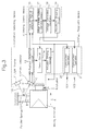
- Fig. 4 is a block diagram showing a control system of the embodiment shown in Fig. 3.
- the reference character (K) denotes a spring constant of the parallel spring 10, (G ca ) a transfer function of the actuator 9, servo circuit 14 and actuator driving circuit 15, (M) weight of the moving mirror 3b, (s) a differential operator, (F) a driving force generated by the actuator 9, (x) a displacement from a neutral position of the moving mirror 3b, ( ⁇ x) the position control signal of the moving mirror 3b.
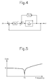
- Fig. 5 is a graph showing a plotted curve of gains of the equation (1), which is the transfer function.
- phase changes stepwise by 180° at the point of the resonance frequency fo in Fig. 6B, it actually does not change stepwise as shown in the figure because of a damping effect of materials. It changes mildly more or less as shown by the broken line A, so that it may be controlled by the driving control means 51 so that it becomes 90°.
- the vibration-proofing may be enhanced by supporting the moving mirror 3b by the parallel spring 10 and by detecting the position of the moving mirror 3b to control the position thereof and the power may be saved by driving at the natural frequency of the spring system.
- Fig. 7 is a structural drawing showing a second embodiment of an interference spectrometer of the present invention.
- the position detecting circuit 13, driving control means 51 and fault diagnosing means 52 are omitted here since their structure is the same.
- the reference numeral (3c) denotes a moving mirror, (9a) an actuator, (10a) an parallel spring, (11a) a light source, (12a) a photo-detector divided into two parts and (22) a plate having an aperture.
- the components 11a, 12a and the position detecting circuit 13 (not shown) compose position detecting means 50a.
- the present embodiment is different from the first embodiment shown in Fig. 3 in that the plate 22 having the aperture is attached to the moving mirror 3c and the light source 11a and photo-detector 12a are disposed so that an output light from the light source 11a transmits through the aperture and the transmitted light enters the photo-detector 12a.
- a portion "A” is the aperture and portions "B” and “C” block the output light from the light source 11a.
- the aperture also moves in the direction of C along that, decreasing light entering a portion "E" of the photo-detector 12a and increasing light entering a portion "F” of the photo-detector 12a.
- the position of the moving mirror 3c may be found similarly to the first embodiment by finding a difference at the portions "E" and "F" of the photo-detector 12a.
- Figs. 8A and 8B are a structural drawing and equivalent circuit diagram illustrating a third embodiment of an interference spectrometer of the present invention.
- the driving control means 51 and fault diagnosing means 52 are omitted since their structure is the same.
- the reference numeral (3d) denotes a moving mirror, (10b and 10c) parallel springs, and (23a, 23b, 23c and 23d) strain gages.
- the present embodiment is different from the first embodiment shown in Fig. 3 in that the moving mirror 3b is supported by the parallel springs 10b and 10c, the strain gages 23b and 23d are attached to the parallel spring 10b and the strain gages 23a and 23c are attached to the parallel spring 10c, respectively, and a bridge circuit is composed by the strain gages 23a through 23d. That is, the position of the moving mirror 3d is detected not optically but by gauging strain.
- Fig. 8B is a circuit diagram showing an equivalent circuit of the bridge circuit composed of the strain gages 23a through 23d.
- the reference numerals 23a through 23d are equivalent to those shown in Fig. 8A.
- a voltage "E” is applied between points b and d in Fig. 8B to detect a potential difference "e” between points a and c in the figure.
- resistance values of the strain gages 23a through 23d are equal respectively to R1, R2, R3 and R4, a distortion factor of each of the strain gages 23a through 23d is "K3" and strains which result in each of the strain gages 23a through 23d are epsilon 1, epsilon 2, epsilon 3 and epsilon 4.
- e K s * E * ( ⁇ 1 - ⁇ 2 + ⁇ 3 - ⁇ 4)/4 (4)
- the strain in the axial direction i.e., the position only in the axial direction, may be found by constructing the bridge circuit by providing the parallel springs 10b and 10c and strain gages 23a through 23d and by detecting the potential difference generated in the bridge circuit.
- the position detecting means may be downsized because the strain gages are used as described in the embodiment illustrated in Fig. 8 and a temperature compensation and position detection error may be eliminated by constructing the bridge circuit by the strain gages.
- the vibration-proofing of the moving mirror may be enhanced by controlling the position of the moving mirror just by detecting its position, not by driving it at the natural frequency of the spring system.
- the method for supporting the moving mirror is not confined only to the parallel spring.
- the present invention is not confined only to those using the optical means or strain gages.
- the fault diagnosing means 52 may be omitted since it is not an essential component in the present invention.
- the present invention has such effects that the vibration-proofing of the moving mirror may be enhanced by detecting its position to control it and that it allows to realize the interference spectrometer which consumes less power by driving the moving mirror at the natural frequency of the spring system composed of the moving mirror and leaf spring.
Landscapes
- Physics & Mathematics (AREA)
- Spectroscopy & Molecular Physics (AREA)
- General Physics & Mathematics (AREA)
- Spectrometry And Color Measurement (AREA)
Abstract
Description
- The present invention relates to an interference spectrometer and more particularly to an interference spectrometer in which vibration-proofing and control characteristics of a moving mirror thereof are enhanced.
- An interference spectrometer causes an interference by dividing an output light from a light source into two optical paths and by changing a length of each optical path. Generally, a moving mirror is used to change the optical path lengths.
- Fig. 1 is a plan view showing one example of such a prior art interference spectrometer, which is described in Japanese Patent Laid-open No. 63-135827. In Fig. 1, the reference numeral (1) denotes a beam splitter, (2) a fixed mirror, (3) a moving mirror, (4) a compensator, (5) an air bearing, (100) an incident light and (101) an interference light.
- The
incident light 100 is input to thebeam splitter 1. A part of theincident light 100 is reflected by thebeam splitter 1 and enters thefixed mirror 2. Remainder of theincident light 100 transmits through thebeam splitter 1 andcompensator 4 and enters themoving mirror 3. - The lights reflected from the
fixed mirror 2 and themoving mirror 3 enter thebeam splitter 1 again and are output as theinterference light 101. The movingmirror 3 is provided on the air bearing 5 and its position is controlled through the control of the air bearing 5. - Fig. 2 is a plan view of one example of another prior art interference spectrometer, which is described in Japanese Utility Model Publication No. 63-1221. In Fig. 2, the reference numeral (1a) denotes a beam splitter, (2a) a fixed mirror, (3a) a moving mirror, (6 and 7) diaphragms, (8) driving means, (100a) an incident light and (101a) an interference light.
- The incident light 100a is input to the
beam splitter 1a and a part thereof is reflected by thebeam splitter 1a and enters thefixed mirror 2a. Remainder of the incident light 100a transmits through thebeam splitter 1a and enters the moving mirror 3a. - The lights reflected from the
fixed mirror 2a and moving mirror 3a enter thebeam splitter 1a again and are output as the interference light 101a. In Fig. 2, the moving mirror 3a is supported by thediaphragms - The prior art example shown in Fig. 1, however, has a problem that although the air bearing is used to smooth the motion of the moving
mirror 3, it has no restraint in an axial direction and hence has less vibration-proofing against a vibration in the axial direction. - The prior art example shown in Fig. 2 also has problems that although a certain degree of restraint in the axial direction may be obtained by the
diaphragms - On the other hand, there is known a method of detecting a speed of the moving mirror by using an interference signal of a He-Ne laser to control the speed of the moving mirror.
- In such prior art example however, since a band of the interference signal of the He-Ne laser depends on the speed of the moving mirror, a control system thereof is also affected by that and a full control cannot be exerted when the moving mirror is driven at low speed. Furthermore, a detectable resolution of the speed of the moving mirror is restricted to about a half of an output wavelength of the He-Ne laser.
- Accordingly, it is an object of the present invention to solve the aforementioned problems of the interference spectrometer by realizing an interference spectrometer in which vibration-proofing of a moving mirror is enhanced and which consumes less power.
- The interference spectrometer which causes an interference by dividing an output light from a light source into two optical paths and by changing a length of each optical path comprises a moving mirror for changing the optical path lengths, position detecting means for detecting a position of the moving mirror and driving control means for controlling the position of the moving mirror based on an output of the position detecting means. Further, it comprises leaf springs for supporting the moving mirror and driving control means for controlling the position of the moving mirror by driving at a natural frequency of a spring system composed of the moving mirror and the leaf springs based on the output of the position detecting means.
- Other and further objects of the present invention will become obvious upon an understanding of the illustrative embodiments about to be described or will be indicated in the appended claims, and various advantages not referred to herein will occur to one skilled in the art upon employment of the invention in practice.
-
- Fig. 1 is a plan view showing one example of a prior art interference spectrometer;
- Fig. 2 is a plan view showing one example of another prior art interference spectrometer;
- Fig. 3 is a structural block diagram illustrating a first preferred embodiment of an interference spectrometer of the present invention;
- Fig. 4 is a block diagram showing a control system of the embodiment shown in Fig. 3;
- Fig. 5 is a graph of a characteristic curve showing a frequency characteristic of a gain of a transfer function "G";
- Figs. 6A and 6B are Bode diagrams of a transfer function "G'";
- Fig. 7 is a structural drawing showing a second embodiment of an interference spectrometer of the present invention; and
- Figs. 8A and 8B are a structural drawing and an equivalent circuit diagram illustrating a third embodiment of an interference spectrometer of the present invention.
- Referring now to the drawings, the present invention will be explained in detail.
- Fig. 3 is a structural block diagram illustrating a first preferred embodiment of an interference spectrometer of the present invention. In Fig. 3, the reference numeral (3b) denotes a moving mirror such as a corner cube mirror, (9) an actuator, (10) a parallel spring, (11) a light source such as a laser diode, (12) a photo-detector divided into two parts, (13) a position detecting circuit, (14) a servo circuit, (15) an actuator driving circuit, (16) a phase difference detecting circuit, (17) a voltage controlled oscillator control circuit, (18) a voltage controlled oscillator, (19) a waveform shaping circuit, (20 and 21) comparison operators, (102) an output light, (103) a reflected light and (104 and 105) fault detection signals.
- Here, the
components 11 through 13 compose position detecting means 50,components components - The moving
mirror 3b is supported by theparallel spring 10 and its position is controlled by theactuator 9. - The output light of the
light source 11 is input to the surface of theparallel spring 10 and thereflected light 103 from theparallel spring 10 is input to the photo-detector 12. Two outputs from the photo-detector 12 are connected respectively to theposition detecting circuit 13 and an output of theposition detecting circuit 13 is connected to theservo circuit 14 and phasedifference detecting circuit 16. - An output of the
servo circuit 14 is connected to theactuator driving circuit 15 and an output of theactuator driving circuit 15 is connected to theactuator 9, phasedifference detecting circuit 16 andcomparison operator 20. - On the other hand, an output of the phase
difference detecting circuit 16 is connected to the voltage controlledoscillator control circuit 17 and an output of the voltage controlledoscillator control circuit 17 is connected to the voltage controlledoscillator 18 andcomparison operator 21. - An output of the voltage controlled
oscillator 18 is connected to thewaveform shaping circuit 19 and an output of thewaveform shaping circuit 19 is connected to theservo circuit 14. Thecomparison operators fault detection signals - Now an operation of the embodiment shown in Fig. 3 will be explained. In the position detecting means 50, a position of the moving
mirror 3b is detected by inputting theoutput light 102 from thelight source 11 to theparallel spring 10, detecting thereflected light 103 by the photo-detector 12 divided into two parts and calculating the lights by theposition detecting circuit 13. - That is, when the moving
mirror 3b moves in the direction of arrow "A" in Fig. 3, theparallel spring 10 deforms as shown by "B", so that morereflected light 103 enters a part "D" rather than part "C" of the photo-detector 12 divided into two parts. The position of the movingmirror 3b is found by calculating the difference of incident light amounts by theposition detecting circuit 13. - In the driving control means 51, the
servo circuit 14 generates a control signal so that a position signal of themoving mirror 3b which is output by theposition detecting circuit 13 coincides with a position control signal which is output by thewaveform shaping circuit 19 and based on the control signal, theactuator driving circuit 15 drives theactuator 9 so as to control the position of the movingmirror 3b. - The phase
difference detecting circuit 16 finds a phase difference of the position signal of the movingmirror 3b and an output of theactuator driving circuit 15 which is proportional to a force generated by theactuator 9. The phase difference will become 90° when the movingmirror 3b is driven at a natural frequency of a spring system composed of the movingmirror 3b and theparallel spring 10. - Accordingly, the voltage controlled
oscillator control circuit 17 controls the voltage controlledoscillator 18 so that the phase difference becomes 90° and thewaveform shaping circuit 19 performs a filtering process and adjustment of gain on the output of the voltage controlledoscillator 18 to output as the position control signal. - Further, in the fault diagnosing means 52, a fault is determined by monitoring the outputs of the
actuator driving circuit 15 and voltage controlledoscillator control circuit 17. That is, when theactuator 9 does not operate due to a disconnection or the like, the output of theactuator driving circuit 15 turns out to be a large value as compare to that during normal operation. Further, when theparallel spring 10 deteriorates due to a metallic fatigue or the like, the natural frequency of the spring system changes. The fault is determined by comparing the output value of theactuator driving circuit 15 and the output change of the voltage controlledoscillator control circuit 17 which is the change of the natural frequency with the normal values by thecomparison operators - The operation when the moving
mirror 3b is driven at the natural frequency of the spring system will be explained in detail with reference to Figs. 4 through 6. - Fig. 4 is a block diagram showing a control system of the embodiment shown in Fig. 3. In the figure, the reference character (K) denotes a spring constant of the
parallel spring 10, (Gca) a transfer function of theactuator 9,servo circuit 14 andactuator driving circuit 15, (M) weight of the movingmirror 3b, (s) a differential operator, (F) a driving force generated by theactuator 9, (x) a displacement from a neutral position of the movingmirror 3b, (Δx) the position control signal of the movingmirror 3b. - Under the above-mentioned condition, the transfer function "G" from the position control signal Δx to the driving force F may be expressed as follows:

Fig. 5 is a graph showing a plotted curve of gains of the equation (1), which is the transfer function. When theactuator 9 is driven by a resonance frequency "fo"; i.e.,

the driving force F may be smaller, i.e., a less power may be consumed, if the position control signal Δx is varied at a constant amplitude. - A transfer function "G'" from the driving force F to the displacement from the neutral position x is:

and Bode diagrams of the transfer function G' become as shown in Figs. 6A and 6B. - Although the phase changes stepwise by 180° at the point of the resonance frequency fo in Fig. 6B, it actually does not change stepwise as shown in the figure because of a damping effect of materials. It changes mildly more or less as shown by the broken line A, so that it may be controlled by the driving control means 51 so that it becomes 90°.
- As a result, the vibration-proofing may be enhanced by supporting the moving
mirror 3b by theparallel spring 10 and by detecting the position of the movingmirror 3b to control the position thereof and the power may be saved by driving at the natural frequency of the spring system. - Fig. 7 is a structural drawing showing a second embodiment of an interference spectrometer of the present invention. The
position detecting circuit 13, driving control means 51 and fault diagnosing means 52 are omitted here since their structure is the same. - In Fig. 7, the reference numeral (3c) denotes a moving mirror, (9a) an actuator, (10a) an parallel spring, (11a) a light source, (12a) a photo-detector divided into two parts and (22) a plate having an aperture. The
components - The present embodiment is different from the first embodiment shown in Fig. 3 in that the
plate 22 having the aperture is attached to the moving mirror 3c and thelight source 11a and photo-detector 12a are disposed so that an output light from thelight source 11a transmits through the aperture and the transmitted light enters the photo-detector 12a. - In the
plate 22 having the aperture, a portion "A" is the aperture and portions "B" and "C" block the output light from thelight source 11a. - When the moving mirror 3c moves in the direction of arrow C in Fig. 7 for example, the aperture also moves in the direction of C along that, decreasing light entering a portion "E" of the photo-
detector 12a and increasing light entering a portion "F" of the photo-detector 12a. - As a result, the position of the moving mirror 3c may be found similarly to the first embodiment by finding a difference at the portions "E" and "F" of the photo-
detector 12a. - Figs. 8A and 8B are a structural drawing and equivalent circuit diagram illustrating a third embodiment of an interference spectrometer of the present invention. Here, the driving control means 51 and fault diagnosing means 52 are omitted since their structure is the same.
- In Fig. 8A, the reference numeral (3d) denotes a moving mirror, (10b and 10c) parallel springs, and (23a, 23b, 23c and 23d) strain gages.
- The present embodiment is different from the first embodiment shown in Fig. 3 in that the moving
mirror 3b is supported by theparallel springs 10b and 10c, thestrain gages parallel spring 10b and thestrain gages 23a and 23c are attached to the parallel spring 10c, respectively, and a bridge circuit is composed by thestrain gages 23a through 23d. That is, the position of the movingmirror 3d is detected not optically but by gauging strain. - Fig. 8B is a circuit diagram showing an equivalent circuit of the bridge circuit composed of the
strain gages 23a through 23d. In the figure, thereference numerals 23a through 23d are equivalent to those shown in Fig. 8A. - An operation of the third embodiment shown in Figs. 8A and 8B will now be explained. A voltage "E" is applied between points b and d in Fig. 8B to detect a potential difference "e" between points a and c in the figure. Consider that resistance values of the
strain gages 23a through 23d are equal respectively to R1, R2, R3 and R4, a distortion factor of each of thestrain gages 23a through 23d is "K₃" and strains which result in each of thestrain gages 23a through 23d areepsilon 1,epsilon 2,epsilon 3 andepsilon 4. - Under the above-mentioned condition, the potential difference e may be approximately expressed as follows:

Consider also a strain in the axial direction "ε a" and a strain caused by a torsional vibration as "εt" assuming that an absolute value of the strain caused by the move of the movingmirror 3d in the axial direction and that of the strain caused by the torsional vibration are equal in thestrain gages 23a through 23d. - When the move in the axial direction and the torsional vibration are applied to the
strain gages 23a through 23d, the strains "ε 1" through "ε 4" may be expressed as follows;


where a direction into which the strain extends in positive. - Here, when the equations (5) through (8) are substituted for the equation (4), the following equation may be obtained;

As a result, the strain in the axial direction, i.e., the position only in the axial direction, may be found by constructing the bridge circuit by providing theparallel springs 10b and 10c andstrain gages 23a through 23d and by detecting the potential difference generated in the bridge circuit. - Further, the position detecting means may be downsized because the strain gages are used as described in the embodiment illustrated in Fig. 8 and a temperature compensation and position detection error may be eliminated by constructing the bridge circuit by the strain gages.
- By the way, the vibration-proofing of the moving mirror may be enhanced by controlling the position of the moving mirror just by detecting its position, not by driving it at the natural frequency of the spring system. In this case, the method for supporting the moving mirror is not confined only to the parallel spring.
- Further, for the detection of position of the moving mirror, the present invention is not confined only to those using the optical means or strain gages.
- Still more, the fault diagnosing means 52 may be omitted since it is not an essential component in the present invention.
- As it is apparent from the above description, the present invention has such effects that the vibration-proofing of the moving mirror may be enhanced by detecting its position to control it and that it allows to realize the interference spectrometer which consumes less power by driving the moving mirror at the natural frequency of the spring system composed of the moving mirror and leaf spring.
- While preferred embodiments of the present invention have been described using specific terms, such description is for illustrative purposes only, and it is to be understood that changes and variations may be made without departing from the spirit or scope of the following claims.
Claims (9)
- An interference spectrometer which causes an interference by dividing an output light from a light source into two optical paths and by changing a length of each optical path, comprising:
a moving mirror for changing said optical path lengths;
position detecting means for detecting a position of said moving mirror; and
driving control means for controlling the position of said moving mirror based on an output of said position detecting means. - The interference spectrometer according to Claim 1, wherein a leaf spring is used for a supporting section of said moving mirror.
- The interference spectrometer according to Claim 1, wherein said position detecting means is adapted to detect an absolute displacement of said moving mirror in analog.
- The interference spectrometer according to Claim 1, wherein said position detecting means comprises a light source for irradiating light to said supporting section of said moving mirror and a photo-detector for detecting a reflected light from said supporting section and detects the position of said moving mirror based on said reflected light.
- The interference spectrometer according to Claim 1, wherein said position detecting means comprises a plate attached to said moving mirror, a light source for irradiating light to said plate and a photo-detector for detecting light transmitted through without being blocked by said plate and detects the position of said moving mirror based on said transmitted light.
- The interference spectrometer according to Claim 5, wherein an aperture is created on said plate attached to said moving mirror and the position of said moving mirror is detected based on the light which transmits through the aperture.
- The interference spectrometer according to Claim 1, wherein said position detecting means comprises strain gages provided at the supporting section of said moving mirror and detects the position of said moving mirror by detecting strains at the supporting section of said moving mirror.
- The interference spectrometer according to Claim 7, wherein a bridge composed of said strain gages is provided at the supporting section of said moving mirror as said position detecting means to detect a displacement only in the moving direction of said moving mirror by canceling an output when a torsional vibration is generated at the supporting section of said moving mirror.
- An interference spectrometer which causes an interference by dividing an output light from a light source into two optical paths and by changing a length of each optical path, comprising:
a moving mirror for changing said optical path lengths;
leaf springs for supporting said moving mirror;
position detecting means for detecting a position of said moving mirror; and
driving control means for controlling the position of said moving mirror by driving at a natural frequency of a spring system composed of said moving mirror and said leaf springs based on an output of said position detecting means.
Priority Applications (1)
| Application Number | Priority Date | Filing Date | Title |
|---|---|---|---|
| EP98100312A EP0840102B1 (en) | 1994-01-19 | 1994-12-15 | Interference spectrometer |
Applications Claiming Priority (2)
| Application Number | Priority Date | Filing Date | Title |
|---|---|---|---|
| JP6004116A JPH07209085A (en) | 1994-01-19 | 1994-01-19 | Fourier spectrometer |
| JP4116/94 | 1994-01-19 |
Related Child Applications (1)
| Application Number | Title | Priority Date | Filing Date |
|---|---|---|---|
| EP98100312.2 Division-Into | 1998-01-09 |
Publications (2)
| Publication Number | Publication Date |
|---|---|
| EP0664443A1 true EP0664443A1 (en) | 1995-07-26 |
| EP0664443B1 EP0664443B1 (en) | 1999-03-03 |
Family
ID=11575821
Family Applications (2)
| Application Number | Title | Priority Date | Filing Date |
|---|---|---|---|
| EP94119866A Expired - Lifetime EP0664443B1 (en) | 1994-01-19 | 1994-12-15 | Interference spectrometer |
| EP98100312A Expired - Lifetime EP0840102B1 (en) | 1994-01-19 | 1994-12-15 | Interference spectrometer |
Family Applications After (1)
| Application Number | Title | Priority Date | Filing Date |
|---|---|---|---|
| EP98100312A Expired - Lifetime EP0840102B1 (en) | 1994-01-19 | 1994-12-15 | Interference spectrometer |
Country Status (4)
| Country | Link |
|---|---|
| US (1) | US5592292A (en) |
| EP (2) | EP0664443B1 (en) |
| JP (1) | JPH07209085A (en) |
| DE (4) | DE69416813T2 (en) |
Cited By (2)
| Publication number | Priority date | Publication date | Assignee | Title |
|---|---|---|---|---|
| CN103528683A (en) * | 2013-10-25 | 2014-01-22 | 武汉大学 | Moving mirror scanning device for FT-IR (Fourier transform infrared spectrometer) |
| EP3270142A4 (en) * | 2015-03-13 | 2018-03-28 | Shimadzu Corporation | Fourier transform spectrophotometer |
Families Citing this family (10)
| Publication number | Priority date | Publication date | Assignee | Title |
|---|---|---|---|---|
| US6322037B1 (en) * | 1999-10-26 | 2001-11-27 | Yokogawa Electric Corporation | Moving mirror support device for photo-interferometer |
| US20020149777A1 (en) * | 2001-04-12 | 2002-10-17 | Schreiber Kenneth C. | Support for a movable mirror in an interferometer |
| US7075738B2 (en) * | 2002-09-27 | 2006-07-11 | Inlight Solutions, Inc. | Linear positioning apparatus |
| US7630081B2 (en) * | 2007-01-12 | 2009-12-08 | Sas Photonics, Llc | Interferometer maintaining optical relationship between elements |
| JP5483950B2 (en) * | 2009-08-10 | 2014-05-07 | キヤノン株式会社 | Optical component holding device |
| JP2011080854A (en) * | 2009-10-07 | 2011-04-21 | Konica Minolta Holdings Inc | Fourier transform spectroscope |
| CA2791411C (en) * | 2011-05-02 | 2017-03-21 | Foss Analytical A/S | Spectrometric instrument |
| JPWO2014112027A1 (en) * | 2013-01-18 | 2017-01-19 | コニカミノルタ株式会社 | Fourier transform spectrometer |
| US11047790B2 (en) | 2016-05-09 | 2021-06-29 | Trustees Of Boston University | Method and system for enhanced single particle reflectance imaging |
| CN110520700B (en) * | 2017-03-16 | 2021-12-28 | 热电科学仪器有限公司 | System and method for an interferometer that resists externally applied forces |
Citations (2)
| Publication number | Priority date | Publication date | Assignee | Title |
|---|---|---|---|---|
| EP0478801A1 (en) * | 1990-04-18 | 1992-04-08 | Advantest Corporation | Michelson interferometer |
| WO1992021072A1 (en) * | 1991-05-22 | 1992-11-26 | Bio-Rad Laboratories, Inc. | Step scanning technique for interferometer |
Family Cites Families (2)
| Publication number | Priority date | Publication date | Assignee | Title |
|---|---|---|---|---|
| JPS62223604A (en) * | 1986-03-26 | 1987-10-01 | Agency Of Ind Science & Technol | Double optical path interference length measuring instrument |
| US5239361A (en) * | 1991-10-25 | 1993-08-24 | Nicolet Instrument Corporation | Dynamic mirror alignment device for the interferometer of an infrared spectrometer |
-
1994
- 1994-01-19 JP JP6004116A patent/JPH07209085A/en active Pending
- 1994-12-12 US US08/353,679 patent/US5592292A/en not_active Expired - Lifetime
- 1994-12-15 DE DE69416813T patent/DE69416813T2/en not_active Expired - Lifetime
- 1994-12-15 DE DE69431679T patent/DE69431679T2/en not_active Expired - Lifetime
- 1994-12-15 EP EP94119866A patent/EP0664443B1/en not_active Expired - Lifetime
- 1994-12-15 EP EP98100312A patent/EP0840102B1/en not_active Expired - Lifetime
- 1994-12-15 DE DE0840102T patent/DE840102T1/en active Pending
- 1994-12-15 DE DE0664443T patent/DE664443T1/en active Pending
Patent Citations (2)
| Publication number | Priority date | Publication date | Assignee | Title |
|---|---|---|---|---|
| EP0478801A1 (en) * | 1990-04-18 | 1992-04-08 | Advantest Corporation | Michelson interferometer |
| WO1992021072A1 (en) * | 1991-05-22 | 1992-11-26 | Bio-Rad Laboratories, Inc. | Step scanning technique for interferometer |
Cited By (4)
| Publication number | Priority date | Publication date | Assignee | Title |
|---|---|---|---|---|
| CN103528683A (en) * | 2013-10-25 | 2014-01-22 | 武汉大学 | Moving mirror scanning device for FT-IR (Fourier transform infrared spectrometer) |
| CN103528683B (en) * | 2013-10-25 | 2015-09-02 | 武汉大学 | A kind of movinglens scanning device for Fourier transformation infrared spectrometer |
| EP3270142A4 (en) * | 2015-03-13 | 2018-03-28 | Shimadzu Corporation | Fourier transform spectrophotometer |
| US10502626B2 (en) | 2015-03-13 | 2019-12-10 | Shimadzu Corporation | Fourier transform type spectrophotometer to control a speed of a moving mirror |
Also Published As
| Publication number | Publication date |
|---|---|
| EP0840102A3 (en) | 1998-05-13 |
| EP0664443B1 (en) | 1999-03-03 |
| DE664443T1 (en) | 1996-02-15 |
| DE69431679D1 (en) | 2002-12-12 |
| DE69416813D1 (en) | 1999-04-08 |
| US5592292A (en) | 1997-01-07 |
| EP0840102A2 (en) | 1998-05-06 |
| DE69416813T2 (en) | 1999-10-07 |
| DE840102T1 (en) | 1998-09-24 |
| DE69431679T2 (en) | 2003-07-17 |
| JPH07209085A (en) | 1995-08-11 |
| EP0840102B1 (en) | 2002-11-06 |
Similar Documents
| Publication | Publication Date | Title |
|---|---|---|
| EP0664443B1 (en) | Interference spectrometer | |
| US4193693A (en) | Velocity servo for continuous scan Fourier interference spectrometer | |
| US5280341A (en) | Feedback controlled differential fiber interferometer | |
| De Wit et al. | Adaptive eccentricity compensation | |
| US5410404A (en) | Fiber grating-based detection system for wavelength encoded fiber sensors | |
| US20050286111A1 (en) | Mirror actuator position sensor systems and methods | |
| US5801939A (en) | Precision positioning control apparatus and precision positioning control method | |
| US5581521A (en) | Device for controlling the motor of a recording and reproducing apparatus | |
| US4129041A (en) | Method and apparatus for receiving ultrasonic waves by optical means | |
| US20160325780A1 (en) | Active Disturbance Rejection For Electrical Power Steering System | |
| US4674882A (en) | Precision optical displacement measuring instrument using servo controlled fiber optic sensor | |
| US4758065A (en) | Fiber optic sensor probe | |
| USH371H (en) | Optical fiber interferometer | |
| EP2706324B1 (en) | Ring laser gyro | |
| US5220397A (en) | Method and apparatus for angle measurement based on the internal reflection effect | |
| GB2147695A (en) | Balancing of interferometric optical fibre sensors | |
| JP4135054B2 (en) | Moving mirror support device for optical interferometer | |
| US6542244B1 (en) | Variable sensitivity acoustic transducer | |
| US4711577A (en) | Optical configuration of fiber optic sensor for symmetric dynamic response about the optical null | |
| JP3114397B2 (en) | Optical device | |
| GB2128735A (en) | Method and apparatus for optically measuring clearance change | |
| JPS60424A (en) | Waveform controlling system of optical beam scanner | |
| JPS63201504A (en) | Optically physical quantity measuring instrument | |
| KR100222953B1 (en) | Method and appratus for controlling servo system | |
| USRE33078E (en) | Optical configuration of fiber optic sensor for symmetric dynamic response about the optical null |
Legal Events
| Date | Code | Title | Description |
|---|---|---|---|
| PUAI | Public reference made under article 153(3) epc to a published international application that has entered the european phase |
Free format text: ORIGINAL CODE: 0009012 |
|
| 17P | Request for examination filed |
Effective date: 19950113 |
|
| AK | Designated contracting states |
Kind code of ref document: A1 Designated state(s): DE FR GB NL |
|
| EL | Fr: translation of claims filed | ||
| DET | De: translation of patent claims | ||
| 17Q | First examination report despatched |
Effective date: 19961205 |
|
| GRAG | Despatch of communication of intention to grant |
Free format text: ORIGINAL CODE: EPIDOS AGRA |
|
| GRAG | Despatch of communication of intention to grant |
Free format text: ORIGINAL CODE: EPIDOS AGRA |
|
| GRAH | Despatch of communication of intention to grant a patent |
Free format text: ORIGINAL CODE: EPIDOS IGRA |
|
| GRAH | Despatch of communication of intention to grant a patent |
Free format text: ORIGINAL CODE: EPIDOS IGRA |
|
| GRAA | (expected) grant |
Free format text: ORIGINAL CODE: 0009210 |
|
| AK | Designated contracting states |
Kind code of ref document: B1 Designated state(s): DE FR GB NL |
|
| REF | Corresponds to: |
Ref document number: 69416813 Country of ref document: DE Date of ref document: 19990408 |
|
| ET | Fr: translation filed | ||
| PLBE | No opposition filed within time limit |
Free format text: ORIGINAL CODE: 0009261 |
|
| STAA | Information on the status of an ep patent application or granted ep patent |
Free format text: STATUS: NO OPPOSITION FILED WITHIN TIME LIMIT |
|
| 26N | No opposition filed | ||
| REG | Reference to a national code |
Ref country code: GB Ref legal event code: IF02 |
|
| PGFP | Annual fee paid to national office [announced via postgrant information from national office to epo] |
Ref country code: NL Payment date: 20091216 Year of fee payment: 16 |
|
| PGFP | Annual fee paid to national office [announced via postgrant information from national office to epo] |
Ref country code: GB Payment date: 20091209 Year of fee payment: 16 Ref country code: FR Payment date: 20091221 Year of fee payment: 16 |
|
| PGFP | Annual fee paid to national office [announced via postgrant information from national office to epo] |
Ref country code: DE Payment date: 20091222 Year of fee payment: 16 |
|
| REG | Reference to a national code |
Ref country code: NL Ref legal event code: V1 Effective date: 20110701 |
|
| GBPC | Gb: european patent ceased through non-payment of renewal fee |
Effective date: 20101215 |
|
| REG | Reference to a national code |
Ref country code: FR Ref legal event code: ST Effective date: 20110831 |
|
| PG25 | Lapsed in a contracting state [announced via postgrant information from national office to epo] |
Ref country code: FR Free format text: LAPSE BECAUSE OF NON-PAYMENT OF DUE FEES Effective date: 20110103 |
|
| REG | Reference to a national code |
Ref country code: DE Ref legal event code: R119 Ref document number: 69416813 Country of ref document: DE Effective date: 20110701 |
|
| PG25 | Lapsed in a contracting state [announced via postgrant information from national office to epo] |
Ref country code: DE Free format text: LAPSE BECAUSE OF NON-PAYMENT OF DUE FEES Effective date: 20110701 Ref country code: GB Free format text: LAPSE BECAUSE OF NON-PAYMENT OF DUE FEES Effective date: 20101215 |
|
| PG25 | Lapsed in a contracting state [announced via postgrant information from national office to epo] |
Ref country code: NL Free format text: LAPSE BECAUSE OF NON-PAYMENT OF DUE FEES Effective date: 20110701 |