EP0661841B1 - Parity and syndrome generation for error detection and correction in digital communication systems - Google Patents
Parity and syndrome generation for error detection and correction in digital communication systems Download PDFInfo
- Publication number
- EP0661841B1 EP0661841B1 EP94309850A EP94309850A EP0661841B1 EP 0661841 B1 EP0661841 B1 EP 0661841B1 EP 94309850 A EP94309850 A EP 94309850A EP 94309850 A EP94309850 A EP 94309850A EP 0661841 B1 EP0661841 B1 EP 0661841B1
- Authority
- EP
- European Patent Office
- Prior art keywords
- polynomial
- decoding
- error
- updating
- degree
- Prior art date
- Legal status (The legal status is an assumption and is not a legal conclusion. Google has not performed a legal analysis and makes no representation as to the accuracy of the status listed.)
- Expired - Lifetime
Links
Images


Classifications
-
- H—ELECTRICITY
- H04—ELECTRIC COMMUNICATION TECHNIQUE
- H04L—TRANSMISSION OF DIGITAL INFORMATION, e.g. TELEGRAPHIC COMMUNICATION
- H04L1/00—Arrangements for detecting or preventing errors in the information received
- H04L1/004—Arrangements for detecting or preventing errors in the information received by using forward error control
- H04L1/0056—Systems characterized by the type of code used
- H04L1/0057—Block codes
-
- H—ELECTRICITY
- H03—ELECTRONIC CIRCUITRY
- H03M—CODING; DECODING; CODE CONVERSION IN GENERAL
- H03M13/00—Coding, decoding or code conversion, for error detection or error correction; Coding theory basic assumptions; Coding bounds; Error probability evaluation methods; Channel models; Simulation or testing of codes
- H03M13/03—Error detection or forward error correction by redundancy in data representation, i.e. code words containing more digits than the source words
- H03M13/05—Error detection or forward error correction by redundancy in data representation, i.e. code words containing more digits than the source words using block codes, i.e. a predetermined number of check bits joined to a predetermined number of information bits
- H03M13/13—Linear codes
- H03M13/15—Cyclic codes, i.e. cyclic shifts of codewords produce other codewords, e.g. codes defined by a generator polynomial, Bose-Chaudhuri-Hocquenghem [BCH] codes
- H03M13/151—Cyclic codes, i.e. cyclic shifts of codewords produce other codewords, e.g. codes defined by a generator polynomial, Bose-Chaudhuri-Hocquenghem [BCH] codes using error location or error correction polynomials
-
- H—ELECTRICITY
- H04—ELECTRIC COMMUNICATION TECHNIQUE
- H04L—TRANSMISSION OF DIGITAL INFORMATION, e.g. TELEGRAPHIC COMMUNICATION
- H04L1/00—Arrangements for detecting or preventing errors in the information received
- H04L1/004—Arrangements for detecting or preventing errors in the information received by using forward error control
- H04L1/0045—Arrangements at the receiver end
Definitions
- the present invention relates to a communication method, which corrects, at a receiving side, a data error caused by a communication path or a storage medium in a digital communication system and a digital storage system, and an apparatus therefor.
- Decoding methods of error-correcting codes can be classified into hard decision decoding methods and soft decision decoding methods.
- a hard decision decoding method is a method of performing error correction for a digital sequence obtained by hard-deciding a reception signal to "0" and "1". Since the arrangement of a decoder is simple, this method is widely used for various media such as a CD (Compact Disk).
- a soft decision decoding method an analog weight indicating a probability of a digital sequence obtained by soft-deciding a reception signal is calculated in addition to the digital sequence, and error correction is performed by utilizing the analog weight. For this reason, this method can sufficiently bring out the capability of error-correcting codes, and can improve the S/N ratio by about 2 to 3 dB as compared to the hard decision decoding method.
- a GMD (Generalized Minimum Distance) decoding method to be described below is one of the soft decision decoding methods, and is known as a decoding method which can almost perform maximum likelihood decoding using an analog weight. If the minimum distance of codes is represented by d, the conventional GMD decoding can correct a maximum of (d-1) errors, and can realize error correction about twice the correction capability obtained by a single hard decision decoding cycle.
- the present invention has been made in consideration of the above-mentioned prior arts, and has its object to provide an improved communication method and an apparatus therefor.
- a decoder for decoding an encoded received word by generalized minimum distance decoding using a remainder decoding algorithm comprising:
- a decoder for decoding an encoded received word by generalized minimum distance decoding using a remainder decoding algorithm comprising:
- a decoding method for decoding an encoded received word by generalized minimum distance decoding using a remainder decoding algorithm comprising:
- a method for decoding an encoded received word by generalized minimum distance decoding using a remainder decoding algorithm comprising:
- a GMD decoding method and an apparatus therefor according to the first embodiment of the present invention will be described below. First, an outline of the GMD decoding method will be briefly described below, and thereafter, a description of the main subject will be given.
- the GMD decoding can correct a maximum of (d-1) errors, and can realize error correction about twice the correction capability by a single hard decision decoding cycle.
- the GMD decoding requires a maximum of (d-1)/2 hard decision decoding cycles, a larger computational complexity is required than the hard decision decoding method which requires only a single decoding cycle, and this method is not used often in practice.
- E. R. Berlekamp proposed a remainder decoding method executed using a remainder polynomial obtained by dividing a received sequence by a generator polynomial of codes, and suggested a possibility of a great decrease in computational complexity required for the GMD decoding if the remainder decoding method was applied to the GMD decoding. Furthermore, E. R. Berlekamp proposed the following algorithm, called a Welch-Berlekamp (WB) algorithm, which efficiently executed remainder decoding. Since then, Morii, Araki, et. al.
- decoding processing based on the algorithm of the conventional GMD decoding does not consider the computational complexity for degrees.
- the decoding processing based on the WB algorithm requires two multipliers 30 and 31 for respectively performing multiplications with a j and b j and two degree check circuits 32 and 33 for checking the degrees of polynomials U j (x) and Q j (x), as shown in Fig. 2, so as to perform discrimination in 4).
- this technique can be applied to decoding processing based on a recursive WB algorithm (to be described later), and decoding processing with a minimum computational complexity as a whole can be realized.
- the discrimination method in the decoding processing which can be realized by a degree check circuit of a polynomial as a feature of the first embodiment will be described below.
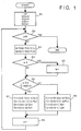
- the decoding processing method of the first embodiment will be described below with reference to the flow chart in Fig. 1.
- This decoding processing method can achieve calculations at a higher speed by a smaller number of circuit components than the conventional WB algorithm since it need not check the degree of the polynomial Q j (x).
- G(x) (x - ⁇ b )•(x - ⁇ b+1 )•••(x - ⁇ b+d-2 )
- N means the error-correcting capability of codes.
- a scalar quantity a j is calculated from the error evaluator polynomial V j (x), the error locator polynomial U j (x), and a syndrome polynomial S(x). Also, a scalar quantity b j is calculated from the auxiliary error evaluator polynomial Q j (x), the auxiliary error locator polynomial P j (x), and the syndrome polynomial S(x).
- x j is numbered by j in the order of lower reliability levels.
- step S7 "j+1"-th degree polynomials V j+1 (x), U j+1 (x), Q j+1 (x), and P j+1 (x) are calculated from j-th degree polynomials, and a j and b j .
- step S9 j is incremented by 1, and the processing from step S2 is repeated.
- Reed-Solomon codes can be decoded by simpler calculations than in the decoding method using the conventional WB algorithm.
- the discrimination processing in step S6 can be realized by, e.g., the circuit arrangement shown in Fig. 3.
- an OR circuit 2 can be realized by a 1-bit OR gate. Therefore, only one degree check circuit for the polynomial U j (x) is required, and the circuit arrangement is simple as a whole.
- the degree checking can be realized with a smaller computational complexity. The superiority of this arrangement can be clearly recognized upon comparison with the circuit shown in Fig. 2. Referring to Fig.
- high-speed decoding processing can be realized by simple calculations as compared to decoding processing based on the conventional WB algorithm.
- the recursive WB algorithm is as follows.
- the decoding processing based on the recursive WB algorithm adopts the circuit arrangement for supporting discrimination processing in 40), as shown in Fig. 5.
- reference numerals 47 and 48 denote registers for respectively storing temporary values of L and L'.
- Adders 50 and 49 respectively increment L and L' stored in the registers 47 and 48 by 1.
- Non-zero detection circuits 43 and 44 are circuits for respectively detecting if values a j and b j are non-zero. If these values are non-zero, the values are supplied to AND circuits 45 and 46, and are logically ANDed to the output values L and L' from the adders 50 and 49, respectively.
- the outputs from the AND circuits 45 and 46 are values indicating the degrees of a j •x L' and b j •x L . These degrees are compared by a comparator 40, and a comparison result is output.
- the decoding processing method of the second embodiment can execute decoding processing based on the recursive WB algorithm at a higher speed by simpler calculations, and will be described below with reference to the flow chart in Fig. 4.
- a calculation associated with L' corresponding to the degree of a polynomial Q j (x) need not be performed as compared to the decoding processing based on the recursive WB algorithm.
- an error locator polynomial U j (x) and an auxiliary error locator polynomial P j (x) are initialized to "0”
- an error evaluator polynomial V j (x) and an auxiliary error evaluator polynomial Q j (x) are initialized to "1".
- P j (x), Q j (x), U j (x), and V j (x) are expressed as elements of a matrix P. L representing the degree of each of the polynomials Q j (x) and U j (x) is initialized to "0".
- N means the error-correcting capability of codes.
- step S15 It is checked in step S15 if a j is "0" or L is larger than "j/2". If L is smaller than "j/2", the flow advances to step S16. Otherwise, the flow advances to step S17 to set a matrix Y as follows, and to increment L by 1:
- step S16 the matrix Y is set as follows:
- step S18 updating calculations of the matrices P and ⁇ are performed.
- step S19 j is incremented by 1, and processing steps from step S11 are executed.
- Decoded data are generated based on the error locator polynomial and the error evaluator polynomial which are obtained, as described above.
- Reed-Solomon codes can be decoded by simpler calculations than in the decoding method using the conventional recursive WB algorithm.
- the discrimination processing in step S15 in the second decoding processing method can be realized by, e.g., the circuit arrangement shown in Fig. 6.
- a comparator 22 compares a j and "0", and outputs the comparison result to an OR circuit 20.
- a register 24 stores a temporary value L. This L is incremented by an adder 23, and is output to a comparator 21 and the register 24.
- the register 24 stores the incremented value L.
- the comparator 21 compares the incremented value L and "j/2", and outputs the comparison result to the OR circuit 20.
- the OR circuit 20 receives the outputs from the comparators 21 and 22, logically ORs these outputs, and outputs a calculation result.
- degree processing can be realized by a smaller circuit with a smaller computational complexity. More specifically, from the circuit arrangement for degree processing based on the recursive algorithm, at least the register 48 and the adder 49 associated with L' can be omitted.
- the degree of Q j (x) is expressed by the degree of U j (x).
- checking (calculation) of the degree (L) of U j (x) can be omitted.
- P j (x) and U j (x) represent error locator polynomials
- Q j (x) and V j (x) represent error evaluator polynomials. Since Q j (x) is no longer related to control of the algorithm according to the present invention, if error evaluator polynomials are not necessary like in BCH codes, Q j (x) and V j (x) themselves can be omitted, and the computational complexity can be further decreased.
- the computational complexity associated with the degree can be decreased, and a GMD decoding algorithm with a minimum total computational complexity can be realized.
- Q j (x) and V j (x) need not be calculated, and the computational complexity can be further decreased.
- Fig. 7 will be briefly described below.
- the time base of the calculations is plotted along an abscissa 70.
- Variables for decoding processing using the WB algorithm are plotted along an ordinate 71.
- the calculation order is as follows. First, a 0 and b 0 are calculated, and P 1 , Q 1 , U 1 , and V 1 are then calculated using these values.
- a 1 and b 1 are calculated from P 1 , Q 1 , U 1 , and V 1 .
- P 2 , Q 2 , U 2 , and V 2 are calculated to calculate a 2 and b 2 ,..., and finally, P p , Q p , U p , and V p are calculated.
- the third embodiment has as its object to provide a parallel decoding processing method which can realize high-speed decoding processing.
- the parallel decoding processing method of the third embodiment will be described in detail below.
- a j and b j can be (x v •y j )-th degree coefficients of the polynomials C(x,y) and D(x,y) .
- C(x,y) and D(x,y) can be updated as follows:
- the WB algorithm can be modified as follows:
- Fig. 8 is a flow chart showing the decoding processing of the above-mentioned decoding algorithm of the third embodiment. The decoding processing will be described below with reference to this flow chart.
- step S82 the (x v •y j )-th degree coefficient of C j (x,y) is set to be a j . Also, the (x v •y j )-th degree coefficient of D j (x,y) is set to be b j .
- step S85 the degree of a j •Q j (x) is compared with the degree of b j •U j (x). If the degree of a j •Q j (x) is smaller than the degree of b j •U j (x), the flow advances to step S86; otherwise, the flow advances to step S87.
- steps S86 and S87 the updating calculations of the polynomials described in the corresponding steps in Fig. 8 are executed.
- step S88 j is incremented by 1, and the flow returns to step S81 to repeat the above processing.
- a j and b j are the (x v •y j )-th degree coefficients of C j (x,y) and D j (x,y). If C j+1 (x,y) or D j+1 (x,y) is sequentially calculated from higher degrees toward lower degrees using C j (x,y) and D j (x,y), the calculations of the (j+1)-th degree polynomials can be started when the (x v •y j )-th degree coefficients of C j (x,y) and D j (x,y) are obtained.
- the decoding processing of the third embodiment can be realized by, e.g., an apparatus shown in Fig. 11
- the respective processing units will be described below.
- a memory 110 stores initial values and their updated values set in step S80.
- the memory 110 is accessed by a control circuit 112 and a polynomial calculation processing circuit 111, as needed.
- the control circuit 112 performs the following control. That is,
- the polynomial calculation processing circuit 111 executes the selected processing, i.e., calculation processing in step S86 or S87, on the basis of the processing request from the control circuit 112.
- control circuit 112 and the polynomial calculation processing circuit 111 need not be separated since they can be executed in a software manner using, e.g., a CPU. Since calculations required in the control circuit 112 and the polynomial calculation processing circuit 111 are simple multiplications/divisions and additions/subtractions of integers, no special processing circuit is required.
- C j (x,y) and D j (x,y) are used for calculating a j and b j as their (x v •y j )-th degree coefficients, and other coefficients are not necessary. Therefore, as described in a well-known continued fraction method (see L. R. Welch and R. A. Scholtz: "Continued fractions and Berlekamp's algorithm", IEEE Trans. Inf. Theory, IT-25, pp. 19-27, Jan 1979), calculations which are not related to the final result can be omitted, and the total computational complexity can be reduced.
- the present invention may be applied to either a system constituted by a plurality of devices or an apparatus consisting of a single device. Also, the present invention may be applied to a case wherein the invention is achieved by supplying a program to a system or apparatus, as a matter of course.
- a high-speed algorithm often means one with a smaller computational complexity.
- an approach which decreases the computational complexity of the algorithm and an approach which improves the degree of parallelism of the algorithm are available. This is because the processing time can be shorted by simultaneously executing a plurality of processing operations by parallel processing.
- a large-scale parallel processing chip can be easily realized due to the recent advance of VLSI techniques. Therefore, an algorithm with a high degree of parallelism is often suitable for high-speed processing.
- the third embodiment is an example of the invention made in consideration of the background that a parallel processing circuit can be realized with low cost due to the advance of the VLSI techniques.
- the decoding processing method of the third embodiment higher-speed-processing with a higher degree of parallelism than the conventional WB algorithm can be realized.
- the conventional WB algorithm requires two different kinds of calculations, i.e., the updating calculations of polynomials and the substitution calculations for calculating a j and b j , while the decoding processing method of the third embodiment requires only the updating calculations of polynomials, thus realizing a simple communication apparatus which can perform high-speed decoding.
- the decoding method and apparatus for communication codes have been described.
- an example of a communication apparatus which comprises these decoding method and apparatus will be described.
- Fig. 12 is a schematic block diagram showing the arrangement of a communication apparatus 120 according to the fourth embodiment.
- the communication apparatus 120 of the fourth embodiment will be described below with reference to Fig. 12.
- a CPU 121 controls the entire communication apparatus 120.
- a control program is pre-stored in a ROM 124, and the CPU 121 executes this control program.
- a keyboard 122 is an input terminal for inputting commands and data for the communication apparatus 120.
- a RAM 123 stores work data and communication data with which the CPU 121 executes various kinds of processing.
- a monitor 125 displays various kinds of processing results in the communication apparatus 120, communication data, input commands from the keyboard 122, and the like.
- An encoder 127 performs encoding processing of communication data stored in the RAM 123, and outputs encoded data onto a communication line 129.
- a decoder 126 decodes encoded data transmitted from an external communication apparatus via a communication line 128, and stores decoded data in the RAM 123.
- the decoder 126 is a portion for performing decoding processing based on the decoding method of one of the first to third embodiments.
- the decoder 126 includes a CPU A 130 for controlling the decoding processing, and a memory 131 which stores a decoding program corresponding to the decoding method.
- received encoded data can be decoded at high speed.
- the present invention may be applied to either a system constituted by a plurality of devices or an apparatus consisting of a single device. Also, the present invention may be applied to a case wherein the invention is achieved by supplying a program to a system or apparatus, as a matter of course.
- communication codes can be decoded at high speed with a minimum computational complexity.
- communication codes can be decoded at highest speed.
Description
- The present invention relates to a communication method, which corrects, at a receiving side, a data error caused by a communication path or a storage medium in a digital communication system and a digital storage system, and an apparatus therefor.
- Decoding methods of error-correcting codes can be classified into hard decision decoding methods and soft decision decoding methods. A hard decision decoding method is a method of performing error correction for a digital sequence obtained by hard-deciding a reception signal to "0" and "1". Since the arrangement of a decoder is simple, this method is widely used for various media such as a CD (Compact Disk).
- On the other hand, in a soft decision decoding method, an analog weight indicating a probability of a digital sequence obtained by soft-deciding a reception signal is calculated in addition to the digital sequence, and error correction is performed by utilizing the analog weight. For this reason, this method can sufficiently bring out the capability of error-correcting codes, and can improve the S/N ratio by about 2 to 3 dB as compared to the hard decision decoding method.
- A GMD (Generalized Minimum Distance) decoding method to be described below is one of the soft decision decoding methods, and is known as a decoding method which can almost perform maximum likelihood decoding using an analog weight. If the minimum distance of codes is represented by d, the conventional GMD decoding can correct a maximum of (d-1) errors, and can realize error correction about twice the correction capability obtained by a single hard decision decoding cycle.
- However, since the GMD decoding requires a maximum of (d-1)/2 hard decision decoding cycles, a larger computational complexity is required than the hard decision decoding method which requires only a single decoding cycle, resulting in a large calculation circuit scale and a long calculation time.
- It is known from ARAKI K. et al., "On a Recursive Form of Welch-Berlekamp Algorithm" published in IECE Transactions of Fundamentals of Electroniccs, Communications and Computer Sciences, vol.E76-A, no.1, January 1993, Tokyo, JP, pages 132-138 to apply a recursive Welch-Berlekamp algorithm to GMD decoding to improve decoding speed.
- The present invention has been made in consideration of the above-mentioned prior arts, and has its object to provide an improved communication method and an apparatus therefor.
- According to the present invention there is disclosed a decoder for decoding an encoded received word by generalized minimum distance decoding using a remainder decoding algorithm, comprising:
- syndrome polynomial generating means for generating a syndrome polynomial on the basis of a received word;
- polynomial updating means for updating an error locator polynomial and an error evaluator polynomial which are set; and
- decoded sequence generating means for generating a decoded sequence on the basis of the error locator polynomial and the error evaluator polynomial, characterised in that
- said polynomial updating means updates the error locator polynomial and the error evaluator polynomial using the generated syndrome polynomial, on the basis of a degree of the error locator polynomial.
-
- According to a further aspect of the present invention there is disclosed a decoder for decoding an encoded received word by generalized minimum distance decoding using a remainder decoding algorithm, comprising:
- syndrome polynomial generating means for generating a syndrome polynomial on the basis of a received word;
- polynomial updating means for updating an error locator polynomial and an error evaluator polynomial which are set; and
- decoded sequence generating means for generating a decoded sequence on the basis of the error locator polynomial and the error evaluator polynomial, characterised in that
- said polynomial updating means further updates a first polynomial generated based on an erasure position of the received word and a second polynomial generated based on the erasure position, and
- said polynomial updating means updates the error locator polynomial, the error evaluator polynomial, the first polynomial, and the second polynomial on the basis of coefficients of a predetermined degree of the first and the second polynomials.
-
- According to a further aspect of the present invention there is disclosed a decoding method for decoding an encoded received word by generalized minimum distance decoding using a remainder decoding algorithm, comprising:
- a syndrome polynomial generating step for generating a syndrome polynomial on the basis of a received word;
- a polynomial updating step for updating an error locator polynomial and an error evaluator polynomial which are set; and
- a decoded sequence generating step for generating a decoded sequence on the basis of the error locator polynomial and the error evaluator polynomial, characterised in that
- in said polynomial updating step, the error locator polynomial and the error evaluator polynomial are updated using the generated syndrome polynomial, on the basis of a degree of the error locator polynomial.
-
- According to a further aspect of the present invention there is disclosed a method for decoding an encoded received word by generalized minimum distance decoding using a remainder decoding algorithm, comprising:
- a syndrome polynomial generating step for generating a syndrom polynomial on the basis of a received word;
- a polynomial updating step for updating an error locator polynomial and an error evaluator polynomial which are set; and
- a decoded sequence generating step for generating a decoded sequence on the basis of the error locator polynomial and the error evaluator polynomial, characterised in that
- in said polynomial updating step, a first polynomial generated based on erasure position of the received word and a second polynomial generated based on the erasure position are further updated, and
- in said polynomial updating step, the error locator polynomial, the error evaluator polynomial, the first polynomial, and the second polynomial are updated on the basis of coefficients of a predetermined degree of the first and the second polynomials.
-
- Further aspects of the invention are set out in the appended claims.
- Other features and advantages of the present invention will be apparent from the following description taken in conjunction with the accompanying drawings, in which like reference characters designate the same or similar parts throughout the figures thereof.
- The accompanying drawings, which are incorporated in and constitute a part of the specification, illustrate embodiment of the present invention and, together with the description, serve to explain the principles of the invention by way of example only.
- Fig. 1 is a flow chart for explaining decoding processing according to the first embodiment of the present invention;
- Fig. 2 is a block diagram for explaining the arrangement of a degree calculation circuit based on a WB algorithm;
- Fig. 3 is a block diagram for explaining the arrangement of a degree calculation circuit of the first embodiment;
- Fig. 4 is a flow chart for explaining decoding processing according to the second embodiment of the present invention;
- Fig. 5 is a block diagram for explaining the arrangement of a degree calculation circuit based on a recursive WB algorithm;
- Fig. 6 is a block diagram for explaining the arrangement of a degree calculation circuit of the second embodiment;
- Fig. 7 is a view for explaining the procedures of decoding processing based on a WB algorithm;
- Fig. 8 is a flow chart for explaining parallel decoding processing according to the third embodiment of the present invention;
- Fig. 9 is a view for explaining parallel processing of the parallel decoding processing of the third embodiment;
- Fig. 10 is a view for explaining parallel processing of the parallel decoding processing of the third embodiment;
- Fig. 11 is a block diagram for explaining the arrangement of a parallel decoding processing circuit of the third embodiment; and
- Fig. 12 is a block diagram for explaining an example of the arrangement of a communication apparatus according to the fourth embodiment of the present invention.
-
- Preferred embodiments of the present invention will be described in detail in accordance with the accompanying drawings.
- A GMD decoding method and an apparatus therefor according to the first embodiment of the present invention will be described below. First, an outline of the GMD decoding method will be briefly described below, and thereafter, a description of the main subject will be given.
- Analog weights which respectively represent probabilities of symbols in a received sequence R = (R0, R1,..., Rn-1) having a code length n are represented by = (0, 1,..., n-1. Note that 0 ≤ i ≤ 1, and if i > j, a symbol Ri in the received sequence R has a higher reliability than Rj.
- A function x(a, b) is defined by:

- At this time, it has already been proved that a received sequence R which satisfies the following inequality can be accurately corrected.
- When processing consisting of the following four steps is repetitively executed a finite number of times, a received sequence R which satisfies inequality (3) can be found out, and it can be accurately corrected:
- Step 1: A test sequence R' is generated by setting j (initial value is 0) symbols in the order from smaller analog weights in the received sequence R to be erasure symbols, and hard-decision-processing other symbols.
- Step 2: A code word C' is obtained by hard-decision decoding the test sequence R'. If the test sequence cannot be corrected, the control advances to step 4.
- Step 3: It is discriminated if the inner product R'·C' of the test sequence R' and the code word C' satisfies inequality (3). If the inequality is satisfied, the code word C is output; otherwise, the control advances to step 4.
- Step 4: "j = j + 2" is performed, and the control returns to step 1. If j ≥ d, since it means that an error exceeding error-correcting capability has occurred, decoding ends.
-
- In this manner, the GMD decoding can correct a maximum of (d-1) errors, and can realize error correction about twice the correction capability by a single hard decision decoding cycle. However, since the GMD decoding requires a maximum of (d-1)/2 hard decision decoding cycles, a larger computational complexity is required than the hard decision decoding method which requires only a single decoding cycle, and this method is not used often in practice.
- For this reason, E. R. Berlekamp proposed a remainder decoding method executed using a remainder polynomial obtained by dividing a received sequence by a generator polynomial of codes, and suggested a possibility of a great decrease in computational complexity required for the GMD decoding if the remainder decoding method was applied to the GMD decoding. Furthermore, E. R. Berlekamp proposed the following algorithm, called a Welch-Berlekamp (WB) algorithm, which efficiently executed remainder decoding. Since then, Morii, Araki, et. al. proved that a maximum of (d-1) errors could be corrected, i.e., the GMD decoding could be performed by a maximum of two cycles of the remainder decoding method, and verified the possibility of the decrease in computational complexity required for the GMD decoding suggested by E. R. Berlekamp.
-
- 1) j = 0, V0(x) = 0, P0(x) = 0, U0(x) = 1, Q0(x) = 1
- 2) if j = 2N then end
- 3)
- aj = Vj(xj) - S(xj) • Uj(xj)
- bj = Qj(xj) - S(xj)•Pj(xj)
- if aj = 0 then bj = 1
- 4) if deg(aj•Qj(x)) < deg (bj•Uj(x)) then
- Vj+1(x) = bj•Vj(x) - aj•Qj(x)
- Uj+1(x) = bj•Uj(x) - aj•Pj(x)
- Qj+1(x) = (x - xj)•Qj(x)
- Pj+1 (x) = (x - xj)•Pj(x) else
- Qj+1(x) = bj•Vj(x) - aj•Qj(x)
- Pj+1(x) = bj•Uj(x) - aj•Pj(x)
- Vj+1(x) = (x - xj)•Vj(x)
- Uj+1(x) = (x - xj)•Uj(x)
- 5) j = j + 1 goto 2)
-
- However, decoding processing based on the algorithm of the conventional GMD decoding does not consider the computational complexity for degrees.
- The decoding processing based on the WB algorithm requires two multipliers 30 and 31 for respectively performing multiplications with aj and bj and two degree check circuits 32 and 33 for checking the degrees of polynomials Uj(x) and Qj(x), as shown in Fig. 2, so as to perform discrimination in 4).
- In the first embodiment, a discrimination method in the decoding processing, which can realize the above-mentioned degree check circuits of the two polynomials by a degree check circuit of a single polynomial will be described.
- Note that this technique can be applied to decoding processing based on a recursive WB algorithm (to be described later), and decoding processing with a minimum computational complexity as a whole can be realized.
- The discrimination method in the decoding processing which can be realized by a degree check circuit of a polynomial as a feature of the first embodiment will be described below.
- Morii & Araki, "Recursive Structure of Welch-Berlekamp Algorithm (IT91-100)" describes that the following formula is established for the WB algorithm:
- In the conditional formula in 4), since aj and bj do not influence degrees of the polynomials if they are not 0, the conditional formula can be rewritten as:
- When formula (4) is substituted in conditional formula (5), we have:
- Since aj = 0 is checked at the end of 3), the computational complexity is not increased. Since the value j is checked upon updating in 5), the check required in formula (6) is the degree of the polynomial Uj(x). Therefore, the computational complexity associated with the degree in the discrimination in 4) can be decreased.
- The decoding processing method of the first embodiment will be described below with reference to the flow chart in Fig. 1. This decoding processing method can achieve calculations at a higher speed by a smaller number of circuit components than the conventional WB algorithm since it need not check the degree of the polynomial Qj(x).
- Assume that a p-element Galois field is represented by GF(p). Processing procedures for decoding Reed-Solomon code using the following generator polynomial on the GF(p) will be explained below.
- where α: primitive element on GF(p)
- d: minimum distance of codes
- b: arbitrary integer
-
- In step S1, a variable j for counting the number of times of processing is initialized, i.e., "j = 0". Also, an error locator polynomial Uj(x) and an auxiliary error locator polynomial Pj(x) are initialized to "0", and an error evaluator polynomial Vj(x) and an auxiliary error evaluator polynomial Qj(x) are initialized to "1".
- In step S2, the variable j for counting the number of times of processing of first decoding processing is compared with a value twice a value N for determining the upper limit value of a predetermined number of times of processing. If j = 2N, the first decoding processing ends. Otherwise, the flow advances to step S3.
- Note that N means the error-correcting capability of codes.
- In step S3, a scalar quantity aj is calculated from the error evaluator polynomial Vj(x), the error locator polynomial Uj(x), and a syndrome polynomial S(x). Also, a scalar quantity bj is calculated from the auxiliary error evaluator polynomial Qj(x), the auxiliary error locator polynomial Pj(x), and the syndrome polynomial S(x).
- Note that the syndrome polynomial S(x) is obtained by calculating the following formulas:

- In step S6, it is checked if aj = "0" or the degree of Uj(x) is larger than "j/2". If this condition is not satisfied, the flow advances to step S8 to calculate "j+1"-th degree polynomials Vj+1(x), Uj+1(x), Qj+1(x), and Pj+1(x).
- In step S7, "j+1"-th degree polynomials Vj+1(x), Uj+1(x), Qj+1(x), and Pj+1(x) are calculated from j-th degree polynomials, and aj and bj.
- In step S9, j is incremented by 1, and the processing from step S2 is repeated.
- With the above-mentioned processing, Reed-Solomon codes can be decoded by simpler calculations than in the decoding method using the conventional WB algorithm.
- Note that the discrimination processing in step S6 can be realized by, e.g., the circuit arrangement shown in Fig. 3. Referring to Fig. 3, a comparator 1 corresponding to "aj = 0" is a 0 detection circuit, and can be very easily realized by, e.g., an EX-OR gate. Also, an OR circuit 2 can be realized by a 1-bit OR gate. Therefore, only one degree check circuit for the polynomial Uj(x) is required, and the circuit arrangement is simple as a whole. Similarly, when the processing is realized in a software manner, the degree checking can be realized with a smaller computational complexity. The superiority of this arrangement can be clearly recognized upon comparison with the circuit shown in Fig. 2. Referring to Fig. 2, since the multipliers 30 and 31 perform multiplications on the Galois field, they require a complicated circuit arrangement as compared to a multiplication of integers. Since two degree check circuits and two multipliers are required, the circuit scale is undesirably large. In contrast to this, the circuit shown in Fig. 3 does not require any multipliers, and requires only one degree check circuit 3, thus realizing a remarkably simple arrangement as compared to the circuit arrangement shown in Fig. 2.
- As described above, according to the first embodiment, high-speed decoding processing can be realized by simple calculations as compared to decoding processing based on the conventional WB algorithm.
- In the second embodiment, a second decoding processing method which can achieve high-speed decoding by simple calculations as compared to a recursive WB algorithm obtained by modifying the WB algorithm (see Morii & Araki, "Recursive Structure of Welch-Berlekamp Algorithm (IT91-100)") will be described below.
- The recursive WB algorithm is as follows.
- Note that the recursive WB algorithm can decrease the total computational complexity as compared to the WB algorithm.
-
- 10) j = 0, L = 0, L' = 0,

- 20) if j = 2N then end
- 30)
- aj = Aj(xj)
- bj = Bj(xj)
- if aj = 0 then bj = 1
- 40) if deg(aj•xL') < deg(bj•xL) then
L' = L' + 1

else
- 50)
- Δ = Y•Δ
- P = Y•P
- 60) j = j + 1 goto 20)
-
- In the decoding processing method of the second embodiment, a decrease in total computational complexity by decreasing the number of variables in calculations is the main objective.
- The decoding processing based on the recursive WB algorithm adopts the circuit arrangement for supporting discrimination processing in 40), as shown in Fig. 5. Referring to Fig. 5, reference numerals 47 and 48 denote registers for respectively storing temporary values of L and L'. Adders 50 and 49 respectively increment L and L' stored in the registers 47 and 48 by 1. Non-zero detection circuits 43 and 44 are circuits for respectively detecting if values aj and bj are non-zero. If these values are non-zero, the values are supplied to AND circuits 45 and 46, and are logically ANDed to the output values L and L' from the adders 50 and 49, respectively. Note that the outputs from the AND circuits 45 and 46 are values indicating the degrees of aj•xL' and bj•xL. These degrees are compared by a comparator 40, and a comparison result is output.
- The decoding processing method of the second embodiment can execute decoding processing based on the recursive WB algorithm at a higher speed by simpler calculations, and will be described below with reference to the flow chart in Fig. 4.
- In the decoding processing method of the second embodiment, a calculation associated with L' corresponding to the degree of a polynomial Qj(x) need not be performed as compared to the decoding processing based on the recursive WB algorithm.
- In step S10, a variable j for counting the number of times of processing is initialized, i.e., "j = 0". Also, an error locator polynomial Uj(x) and an auxiliary error locator polynomial Pj(x) are initialized to "0", and an error evaluator polynomial Vj(x) and an auxiliary error evaluator polynomial Qj(x) are initialized to "1". Assume that Pj(x), Qj(x), Uj(x), and Vj(x) are expressed as elements of a matrix P. L representing the degree of each of the polynomials Qj(x) and Uj(x) is initialized to "0".
- Furthermore, the following polynomials for calculating aj and bj by substituting xj are introduced, and are expressed as elements of a matrix Δ:
- In step S11, the variable j for counting the number of times of processing of second decoding processing is compared with a value twice a value N for determining the upper limit value of a predetermined number of times of processing. If j = 2N, the second decoding processing ends. Otherwise, the flow advances to step S12.
- Note that N means the error-correcting capability of codes.
- In step S12, aj and bj are obtained by substituting xj in Aj(x) and Bj(x). Note that it is checked in step S13 if aj = 0, and if aj = 0, the flow advances to step S14 to set bj = 1.
- It is checked in step S15 if aj is "0" or L is larger than "j/2". If L is smaller than "j/2", the flow advances to step S16. Otherwise, the flow advances to step S17 to set a matrix Y as follows, and to increment L by 1:

- In step S16, the matrix Y is set as follows:

- In step S18, updating calculations of the matrices P and Δ are performed.
- In step S19, j is incremented by 1, and processing steps from step S11 are executed.
- Decoded data are generated based on the error locator polynomial and the error evaluator polynomial which are obtained, as described above.
- With the above-mentioned processing, Reed-Solomon codes can be decoded by simpler calculations than in the decoding method using the conventional recursive WB algorithm.
- The discrimination processing in step S15 in the second decoding processing method can be realized by, e.g., the circuit arrangement shown in Fig. 6. Referring to Fig. 6, a comparator 22 compares aj and "0", and outputs the comparison result to an OR circuit 20. A register 24 stores a temporary value L. This L is incremented by an adder 23, and is output to a comparator 21 and the register 24. The register 24 stores the incremented value L. On the other hand, the comparator 21 compares the incremented value L and "j/2", and outputs the comparison result to the OR circuit 20. The OR circuit 20 receives the outputs from the comparators 21 and 22, logically ORs these outputs, and outputs a calculation result.
- As can be seen from a comparison between the circuit arrangement of degree processing based on the recursive WB algorithm shown in Fig. 5, and the degree processing circuit of the second embodiment, degree processing can be realized by a smaller circuit with a smaller computational complexity. More specifically, from the circuit arrangement for degree processing based on the recursive algorithm, at least the register 48 and the adder 49 associated with L' can be omitted.
- Note that the technique for decreasing the computational complexity associated with the degree is effective not only for the above-mentioned WB algorithm and the recursive WB algorithm, but also for other algorithms having relations of formulas (4) and (5).
- In formula (4), the degree of Qj(x) is expressed by the degree of Uj(x). Alternatively, the degree of Uj(x) can be expressed by the degree of Qj(x) as follows:
- Therefore, the conditional formula in step S15 can also be expressed as follows:
- In this case, in place of the degree (L') of Qj(x), checking (calculation) of the degree (L) of Uj(x) can be omitted.
- Pj(x) and Uj(x) represent error locator polynomials, and Qj(x) and Vj(x) represent error evaluator polynomials. Since Qj(x) is no longer related to control of the algorithm according to the present invention, if error evaluator polynomials are not necessary like in BCH codes, Qj(x) and Vj(x) themselves can be omitted, and the computational complexity can be further decreased.
- As described above, in the decoding processing method of the second embodiment, the computational complexity associated with the degree can be decreased, and a GMD decoding algorithm with a minimum total computational complexity can be realized. When error evaluator polynomials are not necessary like in BCH codes, Qj(x) and Vj(x) need not be calculated, and the computational complexity can be further decreased.
- In the third embodiment, a new decoding method which allows high-speed calculations, based on parallel processing, of the WB algorithm, which cannot be conventionally achieved by parallel processing, will be described below.
- It is difficult for the above-mentioned WB algorithm to parallelly calculate the j-th degree polynomials (Uj(x), Vj(x), Pj(x), Qj(x)) and (j+1)-th degree polynomials (Uj+1(x), Vj+1(x), Pj+1(x), Qj+1(x)). This is because calculations of the (j+1)-th degree polynomials require aj and bj, and aj and bj are calculated using all the coefficients of the j-th degree polynomials. Therefore, since aj and bj are obtained after completion of calculations of the j-th degree polynomials, the calculations of the (j+1)-th degree polynomials can only be started thereafter. Therefore, as shown in Fig. 7, in the WB algorithm, updating calculations of the polynomials are sequentially performed. Fig. 7 will be briefly described below. The time base of the calculations is plotted along an abscissa 70. Variables for decoding processing using the WB algorithm are plotted along an ordinate 71. The calculation order is as follows. First, a0 and b0 are calculated, and P1, Q1, U1, and V1 are then calculated using these values. Then, a1 and b1 are calculated from P1, Q1, U1, and V1. Following the same procedures, P2, Q2, U2, and V2 are calculated to calculate a2 and b2,..., and finally, Pp, Qp, Up, and Vp are calculated.
- Such recurrence calculation procedures also apply to the above-mentioned recursive WB algorithm. Therefore, the WB algorithm and its recursive WB algorithm cannot achieve high-speed processing since they cannot perform parallel processing associated with updating of j.
- Therefore, the third embodiment has as its object to provide a parallel decoding processing method which can realize high-speed decoding processing. The parallel decoding processing method of the third embodiment will be described in detail below.
- First, the following polynomials Aj(x) and Bj(x) are defined:
- Also, the following polynomials Z(x,y), C(x,y), and D(x,y) are defined:(v is an arbitrary integer)


- Therefore, as can be seen from the above formulas, if i = m is set in formulas (14) and (15), aj and bj can be (xv•yj)-th degree coefficients of the polynomials C(x,y) and D(x,y) .
- On the other hand, C(x,y) and D(x,y) can be updated as follows:
- (a) When deg(aj•Qj(x)) < deg(bj•Uj(x))
From - Vj+1(x) = bj•vj(x) - aj•Qj(x)
- Uj+1(x) = bj•Uj(x) - aj•Pj(x)
- Qj+1(x) = (x - xj)•Qj(x)
- Pj+1(x) = (x - xj)•Pj(x) Aj+1(x) and Bj+1(x) are updated as follows:
- Aj+1(x) = bj•Aj(x) - aj•Bj(x)
- Bj+1(x) = (x - xj)•Bj(x)
- Cj+1(x,y) = Aj+1(x) • Z(x,y)
= (bj•Aj(x) - aj•Bj(x))•Z(x,y)
= bj•Cj(x,y) - aj•Dj(x,y) - Dj+1(x,y) = Bj+1(x) • Z(x,y)
= (x - xj) • Bj(x) • Z(x,y)
= (x - xj)•Dj(x,y) - (b) When deg (aj•Qj(x)) ≥ deg (bj•Uj(x))
From - Qj+1(x) = bj•Vj(x) - aj•Qj(x)
- Pj+1(x) = bj•Uj(x) - aj•Pj(x)
- Vj+1(x) = (x - xj)•Vj(x)
- Uj+1(x) = (x - xj)•Uj(x) Aj+1(x) and Bj+1(x) are updated as follows:
- Aj+1(x) = (x - xj)•Aj(x)
- Bj+1(x) = bj•Aj(x) - aj•Bj(x)
- Cj+1(x, y) = Aj+1(x)•Z(x,y)
= (x - xj)Aj(x)•Z(x,y)
= (x - xj)•Cj(x,y) - Dj+1(x,y) = Bj+1(x)•Z(x,y)
= (bj•Aj(x) - aj•Bj(x))•Z(x,y)
= bj•Cj(x,y) - aj•Dj(x,y) -
- Therefore, since aj and bj are (xv•yj)-th degree coefficients of the polynomials Cj(x,y) and Dj(x,y) without calculations in 3) in the WB algorithm described in the first embodiment, the WB algorithm can be modified as follows:
-
- 100) j = 0, C0(x,y) = -S(x)•Z(x,y), D0(x,y) = Z(x,y)
V0(x) = 0, P0(x) = 0, U0(x) = 1, Q0(x) = 1 - 200) if j = p then end
- 300)
- set (xv•yj)-th degree coefficient of Cj(x,y) to be aj
- set (xv•yj)-th degree coefficient of Dj(x,y) to be bj
- if aj = 0 then bj = 1
- 400) if deg (aj•Qj(x)) < deg (bj•Uj(x)) then
- Cj+1(x,y) = bj•Cj(x,y) - aj•Dj(x,y)
- Uj+1(x) = bj•Uj(x) - aj•Pj(x)
- Vj+1(x) = bj•Vj - aj•Qj(x)
- Dj+1(x,y) = (x - xj)•Dj(x,y)
- Pj+1(x) = (x - xj)•Pj(x)
- Qj+1(x) = (x - xj)•Qj(x) else
- Dj+1(x,y) = bj•Cj(x,y) - aj•Dj(x,y)
- Pj+1(x) = bj•Uj(x) - aj•Pj(x)
- Qj+1(x) = bj•Vj(x) - aj•Qj(x)
- Cj+1(x,y) = (x - xj) • Cj(x,y)
- Uj+1(x) = (x - xj)•Uj(x)
- Vj+1(x) = (x - xj)•Vj(x)
- 500) j = j + 1 goto 200
-
- Fig. 8 is a flow chart showing the decoding processing of the above-mentioned decoding algorithm of the third embodiment. The decoding processing will be described below with reference to this flow chart.
- In step S80, a variable j for counting the number of times of processing is initialized, i.e., "j = 0". Also, the polynomials C0(x,y), D0(x,y), V0(x), P0(x), U0(x), and Q0(x) are initialized.
- In step S81, the variable j for counting the number of times of processing is compared with a predetermined number p of times of repetition, and if j = p, the decoding processing ends. Otherwise, the flow advances to step S82.
- In step S82, the (xv•yj)-th degree coefficient of Cj(x,y) is set to be aj. Also, the (xv•yj)-th degree coefficient of Dj(x,y) is set to be bj.
- In step S83, it is checked if aj = 0. If aj = 0, the flow advances to step S84 to set bj = 1.
- In step S85, the degree of aj•Qj(x) is compared with the degree of bj•Uj(x). If the degree of aj•Qj(x) is smaller than the degree of bj•Uj(x), the flow advances to step S86; otherwise, the flow advances to step S87.
- In steps S86 and S87, the updating calculations of the polynomials described in the corresponding steps in Fig. 8 are executed.
- In step S88, j is incremented by 1, and the flow returns to step S81 to repeat the above processing.
- In the decoding method according to the third embodiment described above, parallel processing associated with j can be performed. In the decoding processing of the third embodiment, aj and bj are the (xv•yj)-th degree coefficients of Cj(x,y) and Dj(x,y). If Cj+1(x,y) or Dj+1(x,y) is sequentially calculated from higher degrees toward lower degrees using Cj(x,y) and Dj(x,y), the calculations of the (j+1)-th degree polynomials can be started when the (xv•yj)-th degree coefficients of Cj(x,y) and Dj(x,y) are obtained. This means that parallel calculations of j-th degree polynomials and (j+1)-th degree polynomials can be performed. Therefore, in the decoding method of the third embodiment, the calculations of the j-th degree polynomials can be parallelly executed, as shown in Fig. 9. In Fig. 9, the time base of the calculations is plotted along an abscissa 90. Also, variables for the third decoding processing are plotted along an ordinate 91. As can be seen from Fig. 9, in the decoding processing of the third embodiment, if a plurality of processing circuits for performing updating calculations of polynomials are prepared, the processing speed can be easily increased in proportion to the number of processing circuits. Even when the updating calculation of each j-th degree polynomials is performed by one clock, the calculation time requires only about p clocks, as shown in Fig. 10, and higher-speed calculations than those based on the conventional WB algorithm can be realized. Note that the time base of the calculations is plotted along an abscissa 100 in Fig. 10. In addition, variables for the third decoding processing are plotted along an ordinate 101.
- Therefore, the decoding processing of the third embodiment can be realized by, e.g., an apparatus shown in Fig. 11 The respective processing units will be described below.
- A memory 110 stores initial values and their updated values set in step S80. The memory 110 is accessed by a control circuit 112 and a polynomial calculation processing circuit 111, as needed.
- The control circuit 112 performs the following control. That is,
- a1: It is checked if j is equal to the predetermined number p of times of processing, and if j is not equal to p, the processing in step S82 is selected.
- a2: It is checked if aj is equal to 0, and if aj = 0, bj = 1.
- a3: If aj is not equal to 0, the degree discrimination in step S85 is performed, and the processing in step S86 or S87 is selected in accordance with the discrimination result. After the processing is selected, execution of the selected processing is requested for the polynomial calculation processing circuit 111. The polynomial calculation processing circuit 111 executes the selected processing in accordance with the request.
-
- The polynomial calculation processing circuit 111 executes the selected processing, i.e., calculation processing in step S86 or S87, on the basis of the processing request from the control circuit 112.
- Note that the control circuit 112 and the polynomial calculation processing circuit 111 need not be separated since they can be executed in a software manner using, e.g., a CPU. Since calculations required in the control circuit 112 and the polynomial calculation processing circuit 111 are simple multiplications/divisions and additions/subtractions of integers, no special processing circuit is required.
- Since the updating calculations of Pj+1(x), Qj+1(x), Uj+1(x), Vj+1(x), Cj+1(x), and Dj+1(x) can be simultaneously executed, a plurality of processing circuits may be independently arranged. Alternatively, since the updating calculations of polynomials are achieved by similar processing, they can be executed by a single circuit. As can be understood from the above description, the circuit arrangement for executing the decoding processing of the third embodiment can be simplified.
- Note that the modification technique of the WB algorithm described in the decoding method of the third embodiment can be applied to the recursive algorithm described in "Recursive Structure of Welch-Berlekamp Algorithm (IT91-100)" described above, and high-speed parallel processing of the recursive WB algorithm can be achieved.
- Cj(x,y) and Dj(x,y) are used for calculating aj and bj as their (xv•yj)-th degree coefficients, and other coefficients are not necessary. Therefore, as described in a well-known continued fraction method (see L. R. Welch and R. A. Scholtz: "Continued fractions and Berlekamp's algorithm", IEEE Trans. Inf. Theory, IT-25, pp. 19-27, Jan 1979), calculations which are not related to the final result can be omitted, and the total computational complexity can be reduced.
- Note that the present invention may be applied to either a system constituted by a plurality of devices or an apparatus consisting of a single device. Also, the present invention may be applied to a case wherein the invention is achieved by supplying a program to a system or apparatus, as a matter of course.
- In general, a high-speed algorithm often means one with a smaller computational complexity. However, in order to realize high-speed processing, an approach which decreases the computational complexity of the algorithm and an approach which improves the degree of parallelism of the algorithm are available. This is because the processing time can be shorted by simultaneously executing a plurality of processing operations by parallel processing. A large-scale parallel processing chip can be easily realized due to the recent advance of VLSI techniques. Therefore, an algorithm with a high degree of parallelism is often suitable for high-speed processing. The third embodiment is an example of the invention made in consideration of the background that a parallel processing circuit can be realized with low cost due to the advance of the VLSI techniques.
- As described above, according to the decoding processing method of the third embodiment, higher-speed-processing with a higher degree of parallelism than the conventional WB algorithm can be realized. The conventional WB algorithm requires two different kinds of calculations, i.e., the updating calculations of polynomials and the substitution calculations for calculating aj and bj, while the decoding processing method of the third embodiment requires only the updating calculations of polynomials, thus realizing a simple communication apparatus which can perform high-speed decoding.
- In the first to third embodiments, the decoding method and apparatus for communication codes have been described. In the fourth embodiment, an example of a communication apparatus which comprises these decoding method and apparatus will be described.
- Fig. 12 is a schematic block diagram showing the arrangement of a communication apparatus 120 according to the fourth embodiment. The communication apparatus 120 of the fourth embodiment will be described below with reference to Fig. 12.
- A CPU 121 controls the entire communication apparatus 120. A control program is pre-stored in a ROM 124, and the CPU 121 executes this control program. A keyboard 122 is an input terminal for inputting commands and data for the communication apparatus 120. A RAM 123 stores work data and communication data with which the CPU 121 executes various kinds of processing. A monitor 125 displays various kinds of processing results in the communication apparatus 120, communication data, input commands from the keyboard 122, and the like. An encoder 127 performs encoding processing of communication data stored in the RAM 123, and outputs encoded data onto a communication line 129. A decoder 126 decodes encoded data transmitted from an external communication apparatus via a communication line 128, and stores decoded data in the RAM 123.
- Note that the decoder 126 is a portion for performing decoding processing based on the decoding method of one of the first to third embodiments. The decoder 126 includes a CPU A 130 for controlling the decoding processing, and a memory 131 which stores a decoding program corresponding to the decoding method.
- In the communication apparatus of the fourth embodiment, received encoded data can be decoded at high speed.
- Note that the present invention may be applied to either a system constituted by a plurality of devices or an apparatus consisting of a single device. Also, the present invention may be applied to a case wherein the invention is achieved by supplying a program to a system or apparatus, as a matter of course.
- As described above, according to the present invention, communication codes can be decoded at high speed with a minimum computational complexity.
- According to another aspect of the present invention, communication codes can be decoded at highest speed.
Claims (9)
- A decoder for decoding an encoded received word by generalized minimum distance decoding using a remainder decoding algorithm, comprising:syndrome polynomial generating means for generating a syndrome polynomial (S(x)) on the basis of a received word (R);polynomial updating means for updating an error locator polynomial (Uj(x)) and an error evaluator polynomial (Vj(x)) which are set; anddecoded sequence generating means for generating a decoded sequence (C) on the basis of the error locator polynomial and the error evaluator polynomial, characterised in thatsaid polynomial updating means is adapted to update the error locator polynomial and the error evaluator polynomial using the generated syndrome polynomial, on the basis of a degree of the error locator polynomial.
- The decoder according to claim 1, wherein said polynomial updating means comprises:degree calculating means (3,23,24) for calculating a degree of the error locator polynomial; andupdate control means (2,4,20,21) for controlling the updating of the error locator polynomial and the error evaluator polynomial on the basis of a result of comparison between the calculated degree and a predetermined threshold value.
- A decoder for decoding an encoded received word by generalized minimum distance decoding using a remainder decoding algorithm, comprising:syndrome polynomial generating means for generating a syndrome polynomial (S(x)) on the basis of a received word (R);polynomial updating means (111,112) for updating an error locator polynomial (Uj(x)) and an error evaluator polynomial (Vj(x)) which are set; anddecoded sequence generating means for generating a decoded sequence (C) on the basis of the error locator polynomial and the error evaluator polynomial, characterised in thatsaid polynomial updating means is further adapted to update a first polynomial (Dj(x,y)) generated based on a erasure position (xj) of the received word and a second polynomial (Cj(x,y)) generated based on the erasure position, andsaid polynomial updating means is adapted to update the error locator polynomial, the error evaluator polynomial, the first polynomial, and the second polynomial on the basis of coefficients of a predetermined degree of the first and the second polynomials.
- A communication apparatus (120) comprising a decoder (126) according to any of preceding claims.
- A decoding method for decoding an encoded received word by generalized minimum distance decoding using a remainder decoding algorithm, comprising:a syndrome polynomial generating step for generating a syndrome polynomial (S(x)) on the basis of a received word (R);a polynomial updating step (S7,S8,S16,S17,S18) for updating an error locator polynomial (Uj(x)) and an error evaluator polynomial (Vj(x)) which are set; anda decoded sequence generating step for generating a decoded sequence (C) on the basis of the error locator polynomial and the error evaluator polynomial, characterised in thatin said polynomial updating step, the error locator polynomial and the error evaluator polynomial are updated using the generated syndrome polynomial, on the basis of a degree of the error locator polynomial.
- The method according to claim 5, wherein said polynomial updating step comprises:a degree calculating step (S17) for calculating a degree of the error locator polynomial; andan update control step (S6,S15) for controlling the updating of the error locator polynomial and the error evaluator polynomial on the basis of a result of comparison between the calculated degree and a predetermined threshold value.
- A method for decoding an encoded received word by generalized minimum distance decoding using a remainder decoding algorithm, comprising:a syndrome polynomial generating step for generating a syndrome polynomial (S(x)) on the basis of a received word (R);a polynomial updating step (S86,S87) for updating an error locator polynomial (Uj(x)) and an error evaluator polynomial (Vj(x)) which are set; anda decoded sequence generating step for generating a decoded sequence (C) on the basis of the error locator polynomial and the error evaluator polynomial, characterised in thatin said polynomial updating step, a first polynomial (Dj(x,y)) generated based on erasure position (xj) of the received word and a second polynomial (Cj(x,y)) generated based on the erasure position are further updated, andin said polynomial updating step, the error locator polynomial, the error evaluator polynomial, the first polynomial, and the second polynomial are updated on the basis of coefficients of a predetermined degree of the first and the second polynomials.
- A communication method using the decoding method according to any of claims 5 to 7.
- A computer program comprising processor implementable instructions for causing a decoder to perform all the steps of a method according to any one of claims 5 to 7.
Applications Claiming Priority (3)
| Application Number | Priority Date | Filing Date | Title |
|---|---|---|---|
| JP354518/93 | 1993-12-29 | ||
| JP35451893A JP3245290B2 (en) | 1993-12-29 | 1993-12-29 | Decoding method and device |
| JP35451893 | 1993-12-29 |
Publications (3)
| Publication Number | Publication Date |
|---|---|
| EP0661841A2 EP0661841A2 (en) | 1995-07-05 |
| EP0661841A3 EP0661841A3 (en) | 1995-11-22 |
| EP0661841B1 true EP0661841B1 (en) | 2002-03-27 |
Family
ID=18438102
Family Applications (1)
| Application Number | Title | Priority Date | Filing Date |
|---|---|---|---|
| EP94309850A Expired - Lifetime EP0661841B1 (en) | 1993-12-29 | 1994-12-28 | Parity and syndrome generation for error detection and correction in digital communication systems |
Country Status (4)
| Country | Link |
|---|---|
| US (1) | US5604752A (en) |
| EP (1) | EP0661841B1 (en) |
| JP (1) | JP3245290B2 (en) |
| DE (1) | DE69430236T2 (en) |
Families Citing this family (9)
| Publication number | Priority date | Publication date | Assignee | Title |
|---|---|---|---|---|
| JP3507119B2 (en) * | 1994-03-15 | 2004-03-15 | キヤノン株式会社 | Pseudorandom number generator and communication device using the same |
| JPH0936755A (en) * | 1995-07-21 | 1997-02-07 | Canon Inc | Decoder and its method |
| US7076720B1 (en) | 1999-05-28 | 2006-07-11 | Canon Kabushiki Kaisha | Encoding apparatus and decoding apparatus |
| US6634007B1 (en) * | 1999-11-08 | 2003-10-14 | Codevector Technology | Algebraic soft decoding of reed-solomon codes |
| JP2001359070A (en) * | 2000-06-14 | 2001-12-26 | Canon Inc | Data processing unit, data processing method and computer-readable storage medium |
| JP2003078421A (en) * | 2001-09-04 | 2003-03-14 | Canon Inc | Method and device for detecting first position of code series, and decoding method and device using the sames |
| JP2003324418A (en) * | 2002-02-27 | 2003-11-14 | Canon Inc | Image processor, data process apparatus and method therefor |
| JP2006025409A (en) * | 2004-06-11 | 2006-01-26 | Canon Inc | Apparatus and method for image processing |
| US9419651B2 (en) * | 2008-12-31 | 2016-08-16 | Stmicroelectronics, Inc. | Non-polynomial processing unit for soft-decision error correction coding |
Family Cites Families (3)
| Publication number | Priority date | Publication date | Assignee | Title |
|---|---|---|---|---|
| US4633470A (en) * | 1983-09-27 | 1986-12-30 | Cyclotomics, Inc. | Error correction for algebraic block codes |
| US4649541A (en) * | 1984-11-21 | 1987-03-10 | The United States Of America As Represented By The Administrator Of The National Aeronautics And Space Administration | Reed-Solomon decoder |
| US5323402A (en) * | 1991-02-14 | 1994-06-21 | The Mitre Corporation | Programmable systolic BCH decoder |
-
1993
- 1993-12-29 JP JP35451893A patent/JP3245290B2/en not_active Expired - Fee Related
-
1994
- 1994-12-27 US US08/363,957 patent/US5604752A/en not_active Expired - Lifetime
- 1994-12-28 DE DE69430236T patent/DE69430236T2/en not_active Expired - Lifetime
- 1994-12-28 EP EP94309850A patent/EP0661841B1/en not_active Expired - Lifetime
Also Published As
| Publication number | Publication date |
|---|---|
| EP0661841A2 (en) | 1995-07-05 |
| US5604752A (en) | 1997-02-18 |
| JP3245290B2 (en) | 2002-01-07 |
| DE69430236D1 (en) | 2002-05-02 |
| JPH07202720A (en) | 1995-08-04 |
| EP0661841A3 (en) | 1995-11-22 |
| DE69430236T2 (en) | 2002-09-12 |
Similar Documents
| Publication | Publication Date | Title |
|---|---|---|
| US5440570A (en) | Real-time binary BCH decoder | |
| EP1131893B1 (en) | Forward error corrector | |
| US6631172B1 (en) | Efficient list decoding of Reed-Solomon codes for message recovery in the presence of high noise levels | |
| US5742620A (en) | GMD decoding apparatus and a method therefor | |
| US7502989B2 (en) | Even-load software Reed-Solomon decoder | |
| US6543026B1 (en) | Forward error correction apparatus and methods | |
| US4897839A (en) | Coding and decoding method | |
| US5805617A (en) | Apparatus for computing error correction syndromes | |
| EP0249982B1 (en) | Decoder | |
| EP0661841B1 (en) | Parity and syndrome generation for error detection and correction in digital communication systems | |
| US5583499A (en) | Method and apparatus for computing error locator polynomial for use in a Reed-Solomon decoder | |
| US5315600A (en) | Error correction system including a plurality of processor elements which are capable of performing several kinds of processing for error correction in parallel | |
| EP1458105B1 (en) | Method and device for decoding of Reed-Solomon codes | |
| EP0660535B1 (en) | Apparatus for uniformly correcting erasure and error of received word by using a common polynomial | |
| KR100258951B1 (en) | Rs decoder having serial expansion architecture and method therefor | |
| US6915478B2 (en) | Method and apparatus for computing Reed-Solomon error magnitudes | |
| US20030159103A1 (en) | Efficient method for fast decoding of BCH binary codes | |
| US20030131308A1 (en) | Method and apparatus for solving key equation polynomials in decoding error correction codes | |
| EP0991196B1 (en) | Method of correcting lost data and circuit thereof | |
| US5450420A (en) | Error correction system for correcting errors generated in digital signals | |
| JP2773701B2 (en) | Error correction decoding device | |
| US5978950A (en) | Polynomial evaluator for use in a reed-solomon decoder | |
| JP2575506B2 (en) | Chain search circuit | |
| US6446233B1 (en) | Forward error correction apparatus and methods | |
| EP0825533A1 (en) | Method and circuit for calculating and processing error correction |
Legal Events
| Date | Code | Title | Description |
|---|---|---|---|
| PUAI | Public reference made under article 153(3) epc to a published international application that has entered the european phase |
Free format text: ORIGINAL CODE: 0009012 |
|
| AK | Designated contracting states |
Kind code of ref document: A2 Designated state(s): DE FR GB |
|
| PUAL | Search report despatched |
Free format text: ORIGINAL CODE: 0009013 |
|
| AK | Designated contracting states |
Kind code of ref document: A3 Designated state(s): DE FR GB |
|
| 17P | Request for examination filed |
Effective date: 19960409 |
|
| 17Q | First examination report despatched |
Effective date: 20000131 |
|
| GRAG | Despatch of communication of intention to grant |
Free format text: ORIGINAL CODE: EPIDOS AGRA |
|
| RTI1 | Title (correction) |
Free format text: PARITY AND SYNDROME GENERATION FOR ERROR DETECTION AND CORRECTION IN DIGITAL COMMUNICATION SYSTEMS |
|
| GRAG | Despatch of communication of intention to grant |
Free format text: ORIGINAL CODE: EPIDOS AGRA |
|
| GRAH | Despatch of communication of intention to grant a patent |
Free format text: ORIGINAL CODE: EPIDOS IGRA |
|
| GRAH | Despatch of communication of intention to grant a patent |
Free format text: ORIGINAL CODE: EPIDOS IGRA |
|
| REG | Reference to a national code |
Ref country code: GB Ref legal event code: IF02 |
|
| GRAA | (expected) grant |
Free format text: ORIGINAL CODE: 0009210 |
|
| AK | Designated contracting states |
Kind code of ref document: B1 Designated state(s): DE FR GB |
|
| PG25 | Lapsed in a contracting state [announced via postgrant information from national office to epo] |
Ref country code: FR Free format text: LAPSE BECAUSE OF FAILURE TO SUBMIT A TRANSLATION OF THE DESCRIPTION OR TO PAY THE FEE WITHIN THE PRESCRIBED TIME-LIMIT Effective date: 20020327 |
|
| REF | Corresponds to: |
Ref document number: 69430236 Country of ref document: DE Date of ref document: 20020502 |
|
| EN | Fr: translation not filed | ||
| PLBE | No opposition filed within time limit |
Free format text: ORIGINAL CODE: 0009261 |
|
| STAA | Information on the status of an ep patent application or granted ep patent |
Free format text: STATUS: NO OPPOSITION FILED WITHIN TIME LIMIT |
|
| 26N | No opposition filed |
Effective date: 20021230 |
|
| PGFP | Annual fee paid to national office [announced via postgrant information from national office to epo] |
Ref country code: GB Payment date: 20121219 Year of fee payment: 19 |
|
| PGFP | Annual fee paid to national office [announced via postgrant information from national office to epo] |
Ref country code: DE Payment date: 20121231 Year of fee payment: 19 |
|
| REG | Reference to a national code |
Ref country code: DE Ref legal event code: R119 Ref document number: 69430236 Country of ref document: DE |
|
| GBPC | Gb: european patent ceased through non-payment of renewal fee |
Effective date: 20131228 |
|
| REG | Reference to a national code |
Ref country code: DE Ref legal event code: R119 Ref document number: 69430236 Country of ref document: DE Effective date: 20140701 |
|
| PG25 | Lapsed in a contracting state [announced via postgrant information from national office to epo] |
Ref country code: DE Free format text: LAPSE BECAUSE OF NON-PAYMENT OF DUE FEES Effective date: 20140701 |
|
| PG25 | Lapsed in a contracting state [announced via postgrant information from national office to epo] |
Ref country code: GB Free format text: LAPSE BECAUSE OF NON-PAYMENT OF DUE FEES Effective date: 20131228 |