EP0656671B1 - Orientable antenna with maintenance of the polarisations axes - Google Patents
Orientable antenna with maintenance of the polarisations axes Download PDFInfo
- Publication number
- EP0656671B1 EP0656671B1 EP94402741A EP94402741A EP0656671B1 EP 0656671 B1 EP0656671 B1 EP 0656671B1 EP 94402741 A EP94402741 A EP 94402741A EP 94402741 A EP94402741 A EP 94402741A EP 0656671 B1 EP0656671 B1 EP 0656671B1
- Authority
- EP
- European Patent Office
- Prior art keywords
- reflector
- antenna
- source
- rotation
- antenna according
- Prior art date
- Legal status (The legal status is an assumption and is not a legal conclusion. Google has not performed a legal analysis and makes no representation as to the accuracy of the status listed.)
- Expired - Lifetime
Links
Images


Classifications
-
- H—ELECTRICITY
- H01—ELECTRIC ELEMENTS
- H01Q—ANTENNAS, i.e. RADIO AERIALS
- H01Q3/00—Arrangements for changing or varying the orientation or the shape of the directional pattern of the waves radiated from an antenna or antenna system
- H01Q3/12—Arrangements for changing or varying the orientation or the shape of the directional pattern of the waves radiated from an antenna or antenna system using mechanical relative movement between primary active elements and secondary devices of antennas or antenna systems
- H01Q3/16—Arrangements for changing or varying the orientation or the shape of the directional pattern of the waves radiated from an antenna or antenna system using mechanical relative movement between primary active elements and secondary devices of antennas or antenna systems for varying relative position of primary active element and a reflecting device
-
- H—ELECTRICITY
- H01—ELECTRIC ELEMENTS
- H01Q—ANTENNAS, i.e. RADIO AERIALS
- H01Q19/00—Combinations of primary active antenna elements and units with secondary devices, e.g. with quasi-optical devices, for giving the antenna a desired directional characteristic
- H01Q19/10—Combinations of primary active antenna elements and units with secondary devices, e.g. with quasi-optical devices, for giving the antenna a desired directional characteristic using reflecting surfaces
- H01Q19/18—Combinations of primary active antenna elements and units with secondary devices, e.g. with quasi-optical devices, for giving the antenna a desired directional characteristic using reflecting surfaces having two or more spaced reflecting surfaces
- H01Q19/19—Combinations of primary active antenna elements and units with secondary devices, e.g. with quasi-optical devices, for giving the antenna a desired directional characteristic using reflecting surfaces having two or more spaced reflecting surfaces comprising one main concave reflecting surface associated with an auxiliary reflecting surface
- H01Q19/191—Combinations of primary active antenna elements and units with secondary devices, e.g. with quasi-optical devices, for giving the antenna a desired directional characteristic using reflecting surfaces having two or more spaced reflecting surfaces comprising one main concave reflecting surface associated with an auxiliary reflecting surface wherein the primary active element uses one or more deflecting surfaces, e.g. beam waveguide feeds
-
- H—ELECTRICITY
- H01—ELECTRIC ELEMENTS
- H01Q—ANTENNAS, i.e. RADIO AERIALS
- H01Q19/00—Combinations of primary active antenna elements and units with secondary devices, e.g. with quasi-optical devices, for giving the antenna a desired directional characteristic
- H01Q19/10—Combinations of primary active antenna elements and units with secondary devices, e.g. with quasi-optical devices, for giving the antenna a desired directional characteristic using reflecting surfaces
- H01Q19/18—Combinations of primary active antenna elements and units with secondary devices, e.g. with quasi-optical devices, for giving the antenna a desired directional characteristic using reflecting surfaces having two or more spaced reflecting surfaces
- H01Q19/19—Combinations of primary active antenna elements and units with secondary devices, e.g. with quasi-optical devices, for giving the antenna a desired directional characteristic using reflecting surfaces having two or more spaced reflecting surfaces comprising one main concave reflecting surface associated with an auxiliary reflecting surface
- H01Q19/192—Combinations of primary active antenna elements and units with secondary devices, e.g. with quasi-optical devices, for giving the antenna a desired directional characteristic using reflecting surfaces having two or more spaced reflecting surfaces comprising one main concave reflecting surface associated with an auxiliary reflecting surface with dual offset reflectors
Definitions
- the field of the invention is that of antennas for the emission and / or reception of electromagnetic radiation, and more particularly directive and orientable antennas, capable of emitting and / or receiving radiation in a determined and variable direction.
- Such an antenna may consist of a radiation source and one or more reflector (s), the shape of the reflector (s) and the arrangement of the DU system / reflectors relative to the source determining the directivity of the antenna thus formed as well as the shape of the beam emitted or received.
- An offset system is a system comprising a main reflector, the cut of which is eccentric relative to the axis of the surface considered. In the case of a single reflector, the primary source located on this axis is inclined to target the center of the reflector.
- the invention relates more particularly to antennas capable of transmitting and / or receiving according to two orthogonal linear polarizations, and the success of their mission of which depends on this capacity. This is the case for some telecommunications antennas, for example, which use polarization diversity to allow reuse of the spectrum in a given frequency band. Another example concerns antennas for satellite broadcasting in DBS (Direct Broadcast by Satellite) or DTH (Direct to the Home) systems. Independent measurements according to orthogonal polarizations are also carried out by certain equipment radar, to determine the radar signature of a complex target, for example, or for weather or earth observation radars.
- DBS Direct Broadcast by Satellite
- DTH Direct to the Home
- the present invention for its part, will be particularly advantageous when deployed in space, on board a satellite, an orbital station, a probe, or any other space platform.
- a geostationary telecommunications satellite in most cases, must be able to communicate with a relatively limited number of fixed ground stations.
- the orientations of the axes of orthogonal polarizations used in such a system can be arbitrary provided that some initial adjustments are made to the equipment on the ground before the transmission of the useful information.
- the constraint to accept is that in this case, no temporal variation of the geometric parameters of the link can be tolerated, without causing the need for a new sequence of settings. In the known art, this poses almost no drawback, since the geometric parameters of connection with a geostationary satellite are in principle invariable.
- a linear polarization can be chosen parallel to the trajectory of the satellite, known a priori from ephemerides, and with the other polarization chosen perpendicular to this trajectory and to the nadir.
- Each fixed station on the ground can know in advance the orientations of the polarization axes used by the satellite, and the antenna on the ground can be adjusted accordingly.
- the reuse of frequencies by diversity of polarizations can also provide advantages for direct broadcasting by satellite.
- a ground user will not be obliged to reorient his antenna to target a second satellite in order to receive a second "bouquet" of emissions, if a first satellite can provide the programs of this second bouquet, with those of the first bouquet, from the only orbital position of the first satellite, in cross polarizations.
- the invention seeks to remedy the drawbacks of the prior art for telecommunications satellites (transmit and / or receive antenna) and direct broadcast satellites (transmit antenna only).
- the polarization of the wave received by the equipment can be used to better probe the target.
- backscattering and depolarization of a polarized wave emitted by the satellite can reveal the nature of atmospheric precipitation, since depolarization depends on the size, concentration, and phase state (ice, liquid in droplets). , vapor) of the probed compounds.
- radar backscatter from the sea surface can reveal the state of sea agitation through polarization measurements.
- the sensitivity to polarization is variable depending on the mission.
- the polarization of the initial wave can be arbitrary without influencing the result obtained, precisely because the targets themselves are not fixed but on the contrary of arbitrary orientation.
- the situation is different in the case where one would like to observe a fixed target, illuminated by a polarized wave at separate times in time.
- Such successive measurements can be used to observe the evolution of the target over time, or to improve the signal-to-noise ratio and the resolution of the fixed image by correlation of the successive images (subtraction of the background).
- a typical case is the observation of the same geographical area or the same object on the ground, during the successive passages of a traveling satellite.
- the successive orbits of such a satellite are not generally closed when viewed from the earth's surface, but rather describe a spiral whose step advances in longitude. These are for example heliosynchronous orbits.
- European patent application No. 0.139.482 describes an antenna intended to be used on board a satellite, this antenna being of the Cassegrain type and comprising a source, a primary reflector and a secondary reflector. The two reflectors are integral with one another and the source is fixed. Thus, the source is constantly maintained at the focal point of the antenna, regardless of the position of the reflectors.
- This document does not however deal with the conservation of the orthogonal axes of polarization as a function of the pointing performed. In fact, it does not pose the problem linked to the targeting of non-circular spots, as will be seen later.
- the new problem addressed by the invention is the following: we would like an antenna whose elements can be oriented at will to allow the arbitrary orientation of the beam of radiation emitted or received, while allowing conservation axes of orthogonal linear polarizations, whatever the orientation of the beam.
- the antenna according to the invention must allow the conservation of the axes of orthogonal linear polarizations even in the case of a rotation of the beam around its main direction of propagation.
- the invention proposes an antenna according to claims 1 or 14.
- the source can be a simple horn, a microstrip radiator ("patch" in English), a slot, ... or the source can be a complex or extended source, for example a network of patches or slots, possibly in association with cavities.
- the complex source can be a plurality of separate sources, with a selective polarization reflector or with a plurality of frequency selective reflectors.
- the source can be a direct source or a periscopic source. In short, the invention can be carried out using any source known to those skilled in the art for such applications.
- the movement of at least one reflector comprises a rotation of the reflector around the preferred direction of radiation.
- this movement comprises an angular displacement (deflection) of the preferred direction around a point which represents the position of the source.
- the movement comprises a rotation of the reflector around the direction of propagation of radiation which connects the source and the reflector.
- the direction of propagation between the source and the reflector coincides with the preferred direction of radiation.
- the reflector is a single reflector having parabolic generators, this reflector being illuminated by a source arranged substantially in its focus, and the reflector can be rotated around the direction of radiation while the source is kept fixed.
- the geometry of the assembly is in this case centered.
- the single parabolic reflector is illuminated by a source arranged in an "offset" geometry and the reflector can be rotated around the direction of radiation while the source is held stationary.
- the antenna comprises at least two reflectors arranged in a geometry called "Gregory", offset or centered.
- the two reflectors are arranged with their concave surfaces facing each other, each of them being illuminated either in offset or in center.
- the antenna comprises at least two reflectors arranged in a Cassegrain geometry, including a main reflector which reflects the beam, and an auxiliary reflector which is illuminated by the source. At least the main reflector can be rotated around the preferred direction of radiation while the source is kept stationary. Alternatively, all of the reflectors can be rotated around the preferred direction of radiation while the source is held stationary.
- the antenna further comprises mechanical means for deflecting all of the constituents, without modification of their relative arrangement, in addition to the mechanical means previously described.
- the reflector can be simple or complex.
- a complex reflector can for example be a bigrille reflector consisting of two reflectors arranged one in front of the other in a direction of propagation of the beam, the first reflector having to be reflective for a first linear polarization, and transparent for a second orthogonal linear polarization , which will be reflected by the second reflector located behind said first reflector.
- a bigrille reflector is well known to those skilled in the art.
- the mechanical means allow the rotation of the source, of any shape, while keeping the reflector (s) fixed.
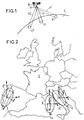
- Figure 1 schematically shows a satellite Q in Earth orbit.
- the satellite has a steerable antenna; according to the position of the reflector 11, the beam can be directed in different directions, to illuminate different places on the earth E.
- the beam F directed according to the nadir illuminate the "spot" 1
- the beams respectively F ', F' 'illuminate the spots 1', 1 '' spot is the English word used by those skilled in the art to designate the path on the ground of a narrow beam directed towards the earth E).
- the beam can be oriented either mechanically by positioning a main reflector 11 as shown schematically in this figure, or electronically in the case of a network antenna by playing on the phases applied to the elementary sources of the network.
- the description of the antenna of the invention will be made in transmission but it is understood that the invention also relates to a reception antenna having the same characteristics, as well as a transmission / reception antenna such as a radar or telecommunications antenna.
- the amplification electronics associated with the antenna must be adapted: either to the power amplification for an antenna at transmission, or to the low noise amplification at reception, or both for a transmit / receive antenna.
- the spot 1 has the shape of an ellipse having axes a, b; the ellipse being elongated along the axis a.
- the axes x, y of polarization coincide with the axes a, b of the elliptical spot 1.
- a rotation of the antenna around the main axis of the beam is obtained by mechanical means which physically rotate the antenna around this main axis.
- this antenna is supplied by one or more sources along two axes of linear orthogonal polarization
- the axes of polarization undergo the same rotation as the axes of the spot on the ground.
- the rotation of the axes of polarization cannot be tolerated, since it would inevitably cause interference between the signals conveyed by channels which are distinct and separated only by their polarization.
- the antenna of the invention makes it possible to solve this problem and to obtain the result illustrated in FIG. 2.
- the spots 1 ', 1'' can be illuminated by a translation and a rotation of the elliptical spot 1, but that the axes of polarization (x, y) are preserved whatever the orientation of the axes (a ', b'; a '', b '') of the elliptical spot (1 ', 1''respectively).
- the elliptical spots are oriented to better cover the geographic areas indicated on a geopolitical map of Europe.
- FIG. 3 shows schematically and in side section a parabolic antenna of the prior art.
- the essential elements of this antenna are the focusing reflector 11 having the shape of a paraboloid of revolution around the axis of symmetry z, and the source 10 placed at the focus of the reflector 11.
- the source of this example is a horn 10 supplied by a waveguide 12.
- Mechanical means 13 are provided to maintain the source 10 at the focus of the reflector 11, in a fixed and optimal geometric arrangement.
- the electromagnetic radiation emitted by the source 10 at the focus is reflected by the reflector 11 according to parallel rays which form a beam F of radiation along the main axis z.
- FIGS. 4A, 4B, 4C are shown different views of an asymmetrical parabolic reflector, capable of making an elongated spot on the ground.
- the shape of the reflector 11 when viewed in plan in FIG. 4B is almost rectangular.
- the sections AA ', BB' shown respectively in FIGS. 4A, 4C, are arcs of paraboloids of different lengths. The arcs can have the same focal length, despite their different lengths, and the reflector 11 will have a single focus. The beam resulting from a source at the focus will have a rectangular section.
- FIG. 5 shows in axial section a conventional Cassegrain geometry, which comprises a source 10 which illuminates an auxiliary reflector 21 through a hole 20 in a main parabolic reflector 11.
- the conventional geometry is axisymmetric around the z axis which corresponds to the direction of propagation of the beam F.
- the source 10 is either arranged on the z axis, or (in a variant not shown) imaged on the axis using a third periscope reflector (not shown).
- the auxiliary reflector 21 in the form of a hyperboloid, the first focus C of which coincides with the focal point of the main parabolic reflector 11, while the phase center of the source 10 is imaged at the second focus C 'of the hyperboloid.
- a ray emitted by the source 10 of the point C 'at an angle of ⁇ with respect to the axis z will be reflected from the surface of the auxiliary reflector 21 towards the main reflector 11 in a direction which will have for its origin the focal point C of the main parabolic reflector 11.
- the rays arriving from the focal point C are reflected by the main parabolic reflector by a reflection angle ⁇ 'to form a beam F whose all the rays are parallel to the axis z.
- the vector N represents the normal to the surface of the auxiliary reflector 21. and the vector N 'represents the normal to the surface of the main reflector 11.
- Figure 6 shows schematically and in three dimensions in perspective the parabolic reflector (11) of Figures 4A, 4B, 4C, with a coordinate system which makes it possible to describe the movements of the antenna according to the invention.
- the top of the reflector 11 is located at the origin 0, and the axis z represents the direction of propagation of the reflected waves (not shown).
- the parabolic reflector 11 has an approximate rectangular shape when viewed in projection on a flat surface perpendicular to the z axis, for example the plane (x, y).
- D is its width in the direction x, and D 'is its height in the direction y.
- a section AA 'in the plane (x, z) describes a parabola
- a section B'B in the plane (y, z) describes a parabola, in accordance with FIGS. 4A 4B and 4C.
- the system has three degrees of freedom of movement: rotation by an angle ⁇ around the axis principal z; and a depointing which can be described by two angles ( ⁇ , ⁇ ) in two orthogonal planes whose intersection is the main axis z.
- the depointing can be represented by the unit vector u ⁇ which is oriented along the angles of directions ( ⁇ , ⁇ , ⁇ ,) to arrive at a point P outside the z axis.
- the angle ⁇ can be expressed as a function of the two independent variables ( ⁇ , ⁇ ).
- the angle ⁇ represents the projection of the vector u ⁇ on the plane (x, y), and the point M the projection of the point P on this same plane (x, y).
- the angle ⁇ represents the projection of the vector u ⁇ on the plane (y, z).
- the projection of point P on this plane is not shown for reasons of clarity of the drawing.
- a rotation of the reflector can be represented either by the angle ⁇ around the main axis z, or by the angle ⁇ 'around the unit vector u ⁇ ; these angles are not independent of each other.
- the assembly comprising the source (10), the reflectors (11, 21) and the mechanical positioning means (depointing, rotation) is fixed by means of the supports S 3 to the platform Q, a satellite for example.
- the positioning means comprise three stepping motors (R ⁇ , R ⁇ , R ⁇ ) capable of effecting angular displacements ( ⁇ , ⁇ , ⁇ ) explained in FIG. 6. These means are mounted on a small platform Q 'which rests on supports S 3 .
- the deflection means (R ⁇ , R ⁇ ) are fixed on the small platform Q 'and drive the support S 2 which supports the axial rotation motor R ⁇ .
- This axial rotation motor R ⁇ is mechanically fixed to the main reflector 11 to perform a rotation ( ⁇ ) of the latter around the main axis z. Unlike the antennas known in the prior art, the rotation of the main reflector 11 does not cause the rotation of the source 10, which is not fixed to the reflector 11.
- the source 10 is supplied with two orthogonal polarizations which also remain fixed relative to the source 10 during a rotation ⁇ of the main reflector.
- FIG. 9 the same embodiment in FIG. 8 is shown in three dimensions and in perspective seen from above.
- the elements already described in Figure 8 have the same references.
- This characteristic already present in the centered Cassegrain geometry, is used according to the invention to isolate the source 10 of rotations ⁇ of the main reflector and of the auxiliary reflector linked to the main 11 around the z axis.
- the projections of points A, A '; B, B 'on the x plane, y are the points a, a'; b, b 'respectively, and gives the lateral dimensions of the main reflector 11 and of the auxiliary reflector 21 fixed to the main reflector 11 by the support rods S 1 .
- these lateral dimensions (aa ', bb') are unequal, and the section of the beam F (not shown) can have an arbitrary shape determined by the shape of the perimeter of the main reflector 11, elliptical in this example.
- the source 10 of this example is a horn, but can be produced according to any other technology known to those skilled in the art.
- the source 10 can be a network of elementary sources produced in microstrip technology.
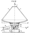
- FIG. 10 schematically shows in axial section another embodiment according to the invention which represents a variant of the antenna shown in FIGS. 8 and 9.
- auxiliary periscopic reflector 14 which receives the radiation from the source 10 offset on the z 'axis parallel to the x axis and perpendicular to the main z axis .
- This auxiliary reflector 14 is arranged in such a way that it reflects the radiation from the source 10 along the z axis to illuminate the hyperbolic auxiliary reflector 21. Everything then takes place according to the description which has been made of FIGS. 8 and 9.
- the source 10 remains stationary relative to the platforms Q and Q ', even during a rotation ⁇ of the main and auxiliary reflector 11 by the motor R ⁇ .
- the position of the auxiliary reflector 14 is adjusted to hold the reflection of the radiation from the source 10 along the main axis z to illuminate the auxiliary reflector 21.
- FIG. 11 shows schematically and in partial section another example of an embodiment according to the invention of an adjustable offset Cassegrain antenna with polarization conservation.
- the main parabolic reflector 11 is illuminated by the source 10 via an auxiliary reflector 15.
- the main reflector is offset offset by the auxiliary reflector at an angle of ⁇ relative to the normal N 'of the main reflector 11 at its summit; the beam F (not shown) is reflected at the same angle ⁇ of the normal N 'along the main axis z.
- the beam deflection is obtained in this example by positioning the main reflector by the means R ⁇ , R ⁇ .
- Different mechanical means of static support are shown (S 5 , S 6 , S 7 ), as well as a removable support S 4 which supports the platform Q '' along the main axis z, while allowing its movement in a perpendicular plane to z.
- Different means of thermal insulation I 1 , I 2 ) are also shown in this figure.
- the main axis z is distant from the illumination axis z 'of the auxiliary reflector 15, and the two axes are parallel.
- a mobile platform Q '' on which the main reflector 11 and the means of the support (S 5 , S 6 , S 7 ) and of depointing (R ⁇ , R ⁇ ) of the latter are mounted, can be moved by the means R ⁇ d ' an angle ⁇ around the z axis of primary illumination. Since the source 10 remains fixed relative to the platform Q (a satellite for example) during a rotation ⁇ around the axis z ', the axes of polarization remain invariant with respect to the platform Q.
- the support means S 8 of the auxiliary reflector 15 connects the latter to the mobile platform Q '', which means that a rotation of the latter does not cause any modification the relative geometry of the two main 11 and auxiliary 15 reflectors.
- the depointing means are mechanical and act on the main reflector, but the invention can also make use of electronic depointing (by phase shifts of the elementary sources in the network) or else, to a depointing effected by mechanical means which act on an auxiliary or auxiliary periscope reflector.
- the rotation of the spot formed on the ground can be obtained either by a rotation ⁇ around the main axis (z), or by a rotation ⁇ of the reflector system (s) around the axis of primary illumination z ', or by a rotation ⁇ ' around a depointed main axis u ⁇ .
- a decoupling of the deflection means and of rotation means around one of the axes (z, z ', u ⁇ ) propagation of electromagnetic radiation allows the orientation of the beam with conservation of the polarization.
Landscapes
- Aerials With Secondary Devices (AREA)
- Variable-Direction Aerials And Aerial Arrays (AREA)
Description
Le domaine de l'invention est celui des antennes pour l'émission et/ou la réception du rayonnement électromagnétique, et plus particulièrement des antennes directives et orientables, aptes à émettre et/ou à recevoir du rayonnement selon une direction déterminée et variable. Une telle antenne peut être constituée par une source de rayonnement et un ou plusieurs réflecteur(s), la forme de de(s) réflecteur(s) et la disposition du système DU/des réflecteurs relativement à la source déterminant la directivité de l'antenne ainsi constituée ainsi que la forme du faisceau émis ou reçu.The field of the invention is that of antennas for the emission and / or reception of electromagnetic radiation, and more particularly directive and orientable antennas, capable of emitting and / or receiving radiation in a determined and variable direction. Such an antenna may consist of a radiation source and one or more reflector (s), the shape of the reflector (s) and the arrangement of the DU system / reflectors relative to the source determining the directivity of the antenna thus formed as well as the shape of the beam emitted or received.
De nombreux exemples d'antennes directives connus de l'homme de l'art peuvent être concernés par la présente invention, telles les antennes dites paraboliques, les antennes Cassegrain, les antennes Gregory et cetera, avec leurs variantes ayant une illumination soit axiale, soit "offset". Un système offset est un système comportant un réflecteur principal dont la découpe est excentrée par rapport à l'axe de la surface considérée. Dans le cas mono réflecteur, la source primaire située sur cet axe est inclinée pour viser le centre du réflecteur.Numerous examples of directional antennas known to those skilled in the art can be concerned with the present invention, such as so-called parabolic antennas, Cassegrain antennas, Gregory et cetera antennas, with their variants having an illumination either axial or "offset". An offset system is a system comprising a main reflector, the cut of which is eccentric relative to the axis of the surface considered. In the case of a single reflector, the primary source located on this axis is inclined to target the center of the reflector.
L'invention concerne plus particulièrement des antennes aptes à émettre et/ou à recevoir selon deux polarisations linéaires orthogonales, et dont le succès de leur mission dépend de cette capacité. Tel est le cas pour certaines antennes de télécommunications, par exemple, qui utilisent la diversité de polarisation pour permettre la réutilisation du spectre dans une bande de fréquences donnée. Un autre exemple concerne des antennes pour la télédiffusion par satellite dans des systèmes DBS (Direct Broadcast by Satellite) ou encore DTH (Direct to the Home). Des mesures indépendantes selon des polarisations orthogonales sont aussi effectuées par certains équipements radar, pour déterminer la signature radar d'une cible complexe, par exemple, ou pour des radars météorologiques ou d'observation de la terre.The invention relates more particularly to antennas capable of transmitting and / or receiving according to two orthogonal linear polarizations, and the success of their mission of which depends on this capacity. This is the case for some telecommunications antennas, for example, which use polarization diversity to allow reuse of the spectrum in a given frequency band. Another example concerns antennas for satellite broadcasting in DBS (Direct Broadcast by Satellite) or DTH (Direct to the Home) systems. Independent measurements according to orthogonal polarizations are also carried out by certain equipment radar, to determine the radar signature of a complex target, for example, or for weather or earth observation radars.
Dans l'art connu, de telles réalisations ont été, dans leur plus grande majorité, des systèmes terrestres fixes voire embarqués sur des plateformes mobiles terrestres ou aéroportés.In the known art, such embodiments have been, for the most part, fixed terrestrial systems or even embedded on mobile terrestrial or airborne platforms.
La présente invention, quant à elle, sera particulièrement avantageuse quand déployée dans l'espace, à bord d'un satellite, d'une station orbitale, d'une sonde, ou de tout autre plateforme spatiale.The present invention, for its part, will be particularly advantageous when deployed in space, on board a satellite, an orbital station, a probe, or any other space platform.
En effet, un nouveau problème peut apparaître quand on veut extrapoler à partir des systèmes terrestres de l'art connu, pour concevoir un système spatial utilisant la diversité de polarisation, à savoir : les axes implicites de référence dont nous jouissons sur la surface terrestre, la verticale et l'horizontale, n'existent pas dans l'espace. En conséquence, la conservation de ces axes comme références est remise en question.Indeed, a new problem can appear when one wants to extrapolate from terrestrial systems of the known art, to conceive a space system using the diversity of polarization, namely: the implicit axes of reference which we enjoy on the terrestrial surface, vertical and horizontal do not exist in space. Consequently, the conservation of these axes as references is questioned.
Ce problème n'est pas insurmontable, et l'on peut même très facilement le résoudre en acceptant différentes contraintes sur le système.This problem is not insurmountable, and one can even very easily solve it by accepting different constraints on the system.
Par exemple, un satellite géostationnaire de télécommunications, le plus souvent, doit pouvoir communiquer avec un nombre relativement limité de stations fixes au sol. Les orientations des axes de polarisations orthogonales utilisées dans un tel système peuvent être arbitraires à condition d'opérer quelques réglages initiaux sur l'équipement au sol avant la transmission des informations utiles. La contrainte à accepter est que dans ce cas, aucune variation temporelle des paramètres géométriques de la liaison ne peut être tolérée, sans entraîner le besoin d'une nouvelle séquence de réglages. Dans l'art connu, ceci ne pose aucun inconvénient ou presque, car les paramètres géométriques de liaison avec un satellite géostationnaire sont en principe invariables.For example, a geostationary telecommunications satellite, in most cases, must be able to communicate with a relatively limited number of fixed ground stations. The orientations of the axes of orthogonal polarizations used in such a system can be arbitrary provided that some initial adjustments are made to the equipment on the ground before the transmission of the useful information. The constraint to accept is that in this case, no temporal variation of the geometric parameters of the link can be tolerated, without causing the need for a new sequence of settings. In the known art, this poses almost no drawback, since the geometric parameters of connection with a geostationary satellite are in principle invariable.
La situation est différente pour un satellite en orbite basse, en orbite polaire, ou en orbite inclinée (orbites Walker, Molnya, et cetera) ; ces orbites pouvant être elliptiques ou circulaires. Les satellites placés sur de telles orbites défilent dans le ciel quand vu par un observateur à partir d'un point fixe sur le globe terrestre. En conséquence, une liaison entre un tel satellite dit "défilant" et une station fixe au sol sera selon une direction qui subit une variation en permanence due au mouvement du satellite.The situation is different for a satellite in low orbit, in polar orbit, or in inclined orbit (Walker, Molnya, et cetera); these orbits can be elliptical or circular. Satellites placed in such orbits parade through the sky when seen by an observer from a fixed point on the earth. Consequently, a link between such a so-called "traveling" satellite and a fixed station on the ground will be in a direction which undergoes a variation continuously due to the movement of the satellite.
Encore, pour ces satellites défilant, il n'y a pas forcément de problème insurmontable à utiliser des polarisations linéaires orthogonales à condition d'accepter certaines contraintes dans la conception du système. Par exemple, une polarisation linéaire peut être choisie parallèle à la trajectoire du satellite, connue a priori à partir d'éphémérides, et avec l'autre polarisation choisie perpendiculaire à cette trajectoire et au nadir. Chaque station fixe au sol peut connaître à l'avance les orientations des axes de polarisation utilisées par le satellite, et l'antenne au sol peut être réglée en conséquence.Still, for these traveling satellites, there is not necessarily an insurmountable problem in using orthogonal linear polarizations provided that certain constraints are accepted in the design of the system. For example, a linear polarization can be chosen parallel to the trajectory of the satellite, known a priori from ephemerides, and with the other polarization chosen perpendicular to this trajectory and to the nadir. Each fixed station on the ground can know in advance the orientations of the polarization axes used by the satellite, and the antenna on the ground can be adjusted accordingly.
L'importance et la fréquence de tels réglages dépendront de la liberté que l'on veut accorder aux paramètres géométriques de la liaison établie entre le satellite défilant et la station au sol. Dans la mesure où la liaison n'est exploitée que lorsque ces paramètres sont identiques ou presque (variations faibles des valeurs pouvant être tolérées dans une fourchette dont la largeur est déterminée par le bilan de liaison en polarisations croisées), il n'y a pas de problème d'interférences à prévoir entre deux canaux de transmission exploités à la même fréquence en polarisations orthogonales (diversité de polarisation).The importance and frequency of such adjustments will depend on the freedom which one wishes to grant to the geometric parameters of the link established between the traveling satellite and the ground station. Insofar as the link is only used when these parameters are almost identical (small variations in the values which can be tolerated in a range whose width is determined by the link budget in cross polarizations), there is no interference problem to be expected between two transmission channels operated at the same frequency in orthogonal polarizations (polarization diversity).
Mais cette contrainte est un problème dans les systèmes connus de l'art antérieur, dans la mesure où la possibilité d'orienter l'antenne embarquée se trouve limitée par les spécifications de performances radioélectriques émises par des administrations nationales et internationales (FCC, CCITT, ITU, et cetera) pour les transmissions par voie hertzienne. Dans les systèmes connus, l'orientation de l'antenne peut faire varier les performances en dehors de la fourchette étroite permise par ces normes et ces spécifications.However, this constraint is a problem in the systems known from the prior art, insofar as the possibility of orienting the on-board antenna is limited by the radio performance specifications issued by national and international administrations (FCC, CCITT, ITU, et cetera) for radio transmissions. In known systems, the orientation of the antenna can vary performance outside the narrow range allowed by these standards and specifications.
La réutilisation de fréquences par diversité de polarisations peut aussi procurer des avantages pour la télédiffusion directe par satellite. Un utilisateur au sol ne sera pas obligé de réorienter son antenne pour viser un deuxième satellite en vue de capter un deuxième "bouquet" d'émissions, si un premier satellite peut fournir les programmes de ce deuxième bouquet, avec ceux du premier bouquet, depuis l'unique position orbitale du premier satellite, en polarisations croisées.The reuse of frequencies by diversity of polarizations can also provide advantages for direct broadcasting by satellite. A ground user will not be obliged to reorient his antenna to target a second satellite in order to receive a second "bouquet" of emissions, if a first satellite can provide the programs of this second bouquet, with those of the first bouquet, from the only orbital position of the first satellite, in cross polarizations.
L'invention cherche à remédier aux inconvénients de l'art antérieur pour les satellites de télécommunications (antenne émission et/ou réception) et les satellites de télédiffusion directe (antenne émission uniquement).The invention seeks to remedy the drawbacks of the prior art for telecommunications satellites (transmit and / or receive antenna) and direct broadcast satellites (transmit antenna only).
Dans les systèmes de radar météorologique embarqué et d'observation de la terre, la polarisation de l'onde reçue par l'équipement peut être utilisée pour mieux sonder la cible. Par exemple, la rétrodiffusion et la dépolarisation d'une onde polarisée émise par le satellite peuvent révéler la nature des précipitations atmosphériques, car la dépolarisation dépend de la taille, de la concentration, et de l'état de phase (glace, liquide en gouttelettes, vapeur) des composés sondés. Dans un autre exemple, la rétrodiffusion radar à partir de la surface de la mer peut révéler l'état d'agitation de la mer par le biais de mesures en polarisation.In on-board weather radar and earth observation systems, the polarization of the wave received by the equipment can be used to better probe the target. For example, backscattering and depolarization of a polarized wave emitted by the satellite can reveal the nature of atmospheric precipitation, since depolarization depends on the size, concentration, and phase state (ice, liquid in droplets). , vapor) of the probed compounds. In another example, radar backscatter from the sea surface can reveal the state of sea agitation through polarization measurements.
La sensibilité à la polarisation est variable suivant la mission. Pour ces deux derniers exemples, la polarisation de l'onde initiale peut être arbitraire sans influer sur le résultat obtenu, justement parce que les cibles elles-mêmes ne sont pas fixes mais au contraire d'orientation arbitraire.The sensitivity to polarization is variable depending on the mission. For these last two examples, the polarization of the initial wave can be arbitrary without influencing the result obtained, precisely because the targets themselves are not fixed but on the contrary of arbitrary orientation.
La situation est différente dans le cas où l'on voudrait observer une cible fixe, illuminée par une onde polarisée à des moments séparés dans le temps. De telles mesures successives peuvent servir à observer l'évolution de la cible dans le temps, ou bien pour améliorer le rapport de signal sur bruit et la résolution de l'image fixe par corrélation des images successives (soustraction du fond). Un cas typique en est l'observation d'une même aire géographique ou d'un même objet au sol, lors des passages successifs d'un satellite défilant. Les orbites successives d'un tel satellite ne sont pas closes en général quand vues de la surface terrestre, mais décrivent plutôt une spirale dont le pas avance en longitude. Ce sont par exemple des orbites héliosynchrones.The situation is different in the case where one would like to observe a fixed target, illuminated by a polarized wave at separate times in time. Such successive measurements can be used to observe the evolution of the target over time, or to improve the signal-to-noise ratio and the resolution of the fixed image by correlation of the successive images (subtraction of the background). A typical case is the observation of the same geographical area or the same object on the ground, during the successive passages of a traveling satellite. The successive orbits of such a satellite are not generally closed when viewed from the earth's surface, but rather describe a spiral whose step advances in longitude. These are for example heliosynchronous orbits.
Un problème avec un tel système de l'art antérieur est que les vecteurs de polarisations orthogonales, alors qu'ils peuvent être arbitraires pour des observations isolées, doivent être conservés pour effectuer la corrélation de mesures successives. Or, ces vecteurs ont tendance à évoluer pour au moins deux raisons : d'une part, la précession de l'orbite introduit des facteurs géométriques variables mais prévisibles ; d'autre part la visée au sol d'un même endroit à partir d'orbites successives engendre d'autres variations de paramètres géométriques, qui doivent être prises en compte dans les corrélations à effectuer.A problem with such a system of the prior art is that the vectors of orthogonal polarizations, while they can be arbitrary for isolated observations, must be kept to perform the correlation of successive measurements. However, these vectors tend to evolve for at least two reasons: on the one hand, the precession of the orbit introduces variable but predictable geometric factors; on the other hand the aiming on the ground of a same place from successive orbits generates other variations of geometric parameters, which must be taken into account in the correlations to be made.
La demande de brevet européen n°0.139.482 décrit une antenne destinée à être utilisée à bord d'un satellite, cette antenne étant de type Cassegrain et comprenant une source, un réflecteur primaire et un réflecteur secondaire. Les deux réflecteurs sont solidaires l'un de l'autre et la source est fixe. Ainsi, la source est constamment maintenue au point focal de l'antenne, quelle que soit la position des réflecteurs. Ce document ne traite cependant pas de la conservation des axes de polarisation orthogonaux en fonction du pointage réalisé. En fait, il ne pose pas le problème lié à la visée de spots non circulaires, comme il sera vu par la suite.European patent application No. 0.139.482 describes an antenna intended to be used on board a satellite, this antenna being of the Cassegrain type and comprising a source, a primary reflector and a secondary reflector. The two reflectors are integral with one another and the source is fixed. Thus, the source is constantly maintained at the focal point of the antenna, regardless of the position of the reflectors. This document does not however deal with the conservation of the orthogonal axes of polarization as a function of the pointing performed. In fact, it does not pose the problem linked to the targeting of non-circular spots, as will be seen later.
Exprimé de façon la plus générale, le nouveau problème adressé par l'invention est le suivant : on voudrait une antenne dont les éléments peuvent être orientés à volonté pour permettre l'orientation arbitraire du faisceau de rayonnement émis ou reçu, tout en permettant la conservation des axes de polarisations linéaires orthogonales, quelle que soit l'orientation du faisceau. De plus, l'antenne selon l'invention doit permettre la conservation des axes de polarisations linéaires orthogonales même dans le cas d'une rotation du faisceau autour de sa direction principale de propagation.Expressed in the most general way, the new problem addressed by the invention is the following: we would like an antenna whose elements can be oriented at will to allow the arbitrary orientation of the beam of radiation emitted or received, while allowing conservation axes of orthogonal linear polarizations, whatever the orientation of the beam. In addition, the antenna according to the invention must allow the conservation of the axes of orthogonal linear polarizations even in the case of a rotation of the beam around its main direction of propagation.
Pour résoudre ce problème, l'invention propose une antenne selon les revendications 1 ou 14.To solve this problem, the invention proposes an antenna according to
La nature de la source sera déterminée par le concepteur selon la mission à accomplir. Par exemple, la source peut être un simple cornet, un radiateur microruban ("patch" en anglais), une fente,... ou encore la source peut être une source complexe ou étendue, par exemple un réseau de patches ou de fentes, éventuellement en association avec des cavités. La source complexe peut être une pluralité de sources séparées, avec un réflecteur sélectif en polarisation ou avec une pluralité de réflecteurs sélectifs en fréquence. La source peut être une source directe ou une source périscopique. Bref, l'invention peut être réalisée utilisant toute source connue de l'homme de l'art pour de telles applications.The nature of the source will be determined by the designer according to the mission to be accomplished. For example, the source can be a simple horn, a microstrip radiator ("patch" in English), a slot, ... or the source can be a complex or extended source, for example a network of patches or slots, possibly in association with cavities. The complex source can be a plurality of separate sources, with a selective polarization reflector or with a plurality of frequency selective reflectors. The source can be a direct source or a periscopic source. In short, the invention can be carried out using any source known to those skilled in the art for such applications.
Selon une caractéristique de l'invention, le mouvement d'au moins un réflecteur comprend une rotation du réflecteur autour de la direction privilégiée de rayonnement. Selon une autre caractéristique, ce mouvement comprend un déplacement angulaire (dépointage) de la direction privilégiée autour d'un point qui représente la position de la source. Selon une variante, le mouvement comprend une rotation du réflecteur autour de la direction de propagation de rayonnement qui relie la source et le réflecteur.According to a characteristic of the invention, the movement of at least one reflector comprises a rotation of the reflector around the preferred direction of radiation. According to another characteristic, this movement comprises an angular displacement (deflection) of the preferred direction around a point which represents the position of the source. According to a variant, the movement comprises a rotation of the reflector around the direction of propagation of radiation which connects the source and the reflector.
Selon une caractéristique particulière, la direction de propagation entre la source et le réflecteur coïncide avec la direction privilégiée de rayonnement.According to a particular characteristic, the direction of propagation between the source and the reflector coincides with the preferred direction of radiation.
Selon une réalisation particulière de l'invention, le réflecteur est un réflecteur unique ayant des génératrices paraboliques, ce réflecteur étant illuminé par une source disposée sensiblement en son foyer, et le réflecteur peut être tourné autour de la direction de rayonnement tandis que la source est maintenue fixe. La géométrie de l'ensemble est dans ce cas centrée.According to a particular embodiment of the invention, the reflector is a single reflector having parabolic generators, this reflector being illuminated by a source arranged substantially in its focus, and the reflector can be rotated around the direction of radiation while the source is kept fixed. The geometry of the assembly is in this case centered.
Selon une variante, le réflecteur parabolique unique est illuminé par une source disposée dans une géométrie "offset" et le réflecteur peut être tourné autour de la direction de rayonnement tandis que la source est maintenue fixe.Alternatively, the single parabolic reflector is illuminated by a source arranged in an "offset" geometry and the reflector can be rotated around the direction of radiation while the source is held stationary.
Selon une autre réalisation particulière, l'antenne comprend au moins deux réflecteurs disposés selon une géométrie dite "Gregory", offset ou centrée. Les deux réflecteurs sont disposés avec leurs surfaces concaves se faisant face, chacun d'eux étant illuminé soit en offset, soit en centrée.According to another particular embodiment, the antenna comprises at least two reflectors arranged in a geometry called "Gregory", offset or centered. The two reflectors are arranged with their concave surfaces facing each other, each of them being illuminated either in offset or in center.
Selon une autre réalisation particulièrement avantageuse, l'antenne comprend au moins deux réflecteurs disposés dans une géométrie Cassegrain, dont un réflecteur principal qui réfléchit le faisceau, et un réflecteur auxiliaire qui est illuminé par la source. Au moins le réflecteur principal peut être tourné autour de la direction privilégiée de rayonnement tandis que la source est maintenue fixe. Selon une variante, l'ensemble des réflecteurs peut être tourné autour de la direction privilégiée de rayonnement tandis que la source est maintenue fixe. Selon une caractéristique additionnelle, l'antenne comprend en outre des moyens mécaniques de dépointage de l'ensemble des constituants, sans modification de leur disposition relative, en plus des moyens mécaniques précédemment décrits.According to another particularly advantageous embodiment, the antenna comprises at least two reflectors arranged in a Cassegrain geometry, including a main reflector which reflects the beam, and an auxiliary reflector which is illuminated by the source. At least the main reflector can be rotated around the preferred direction of radiation while the source is kept stationary. Alternatively, all of the reflectors can be rotated around the preferred direction of radiation while the source is held stationary. According to an additional characteristic, the antenna further comprises mechanical means for deflecting all of the constituents, without modification of their relative arrangement, in addition to the mechanical means previously described.
Dans toute les réalisations les réflecteurs focalisant sont d'une forme arbitraire ; toutefois, l'invention sera particulièrement avantageuse si au moins un réflecteur ne comporte pas de symétrie axiale (de rotation autour d'un axe).In all the embodiments the focusing reflectors are of an arbitrary shape; however, the invention will be particularly advantageous if at least one reflector does not have axial symmetry (of rotation about an axis).
Le réflecteur peut être simple ou complexe.The reflector can be simple or complex.
Un réflecteur complexe peut être par exemple un réflecteur bigrille constitué de deux réflecteurs disposés l'un devant l'autre selon une direction de propagation du faisceau, le premier réflecteur devant être réfléchissant pour une première polarisation linéaire, et transparent pour une deuxième polarisation linéaire orthogonale, qui sera réfléchie par le deuxième réflecteur situé derrière ledit premier réflecteur. Un tel réflecteur bigrille est bien connu de l'homme de l'art. Dans une variante de l'invention utilisant un réflecteur bigrille, les moyens mécaniques permettent la rotation de la source, de forme quelconque, tout en maintenant le(s) réflecteur(s) fixe(s).A complex reflector can for example be a bigrille reflector consisting of two reflectors arranged one in front of the other in a direction of propagation of the beam, the first reflector having to be reflective for a first linear polarization, and transparent for a second orthogonal linear polarization , which will be reflected by the second reflector located behind said first reflector. Such a bigrille reflector is well known to those skilled in the art. In a variant of the invention using a bigrille reflector, the mechanical means allow the rotation of the source, of any shape, while keeping the reflector (s) fixed.
D'autres caractéristiques et avantages de l'invention apparaîtront à la lecture de la description détaillée qui suit, avec ses dessins annexés, dont :
- la figure 1 montre schématiquement un satellite avec un faisceau orientable sur orbite terrestre ;
- la figure 2 montre schématiquement les tracés au sol d'un faisceau orientable d'une antenne orientable selon l'invention avec conservation de la polarisation ;
- la figure 3 montre schématiquement et en coupe latérale une antenne parabolique selon l'art antérieur ;
- les figures 4A, 4B, 4C montrent respectivement en coupe AA', en plan, et en coupe BB', un réflecteur parabolique asymétrique selon une variante de l'invention ;
- la figure 5 montre schématiquement et en coupe la géométrie Cassegrain centrée ;
- la figure 6 montre schématiquement en trois dimensions et en perspective, le réflecteur parabolique des figures 4A, 4B, 4C avec un système de coordonnées qui permet de décrire les mouvements de l'antenne selon l'invention ;
- la figure 7 montre schématiquement et en coupe une géométrie Gregory à l'illumination en offset ;
- la figure 8 montre schématiquement et vue de côté, un exemple d'une réalisation d'une antenne Cassegrain selon l'invention ;
- la figure 9 montre schématiquement en trois dimensions et en vue plongeante, l'exemple de réalisation de la figure 8 ;
- la figure 10 montre un autre exemple en coupe axiale d'une réalisation d'antenne selon l'invention, dans une géométrie Cassegrain centrée avec adjonction d'un réflecteur périscopique auxiliaire et la source déportée ;
- la figure 11 montre schématiquement et en coupe partielle, un autre exemple d'une réalisation d'antenne selon l'invention, dans une géométrie Cassegrain offset.
- FIG. 1 schematically shows a satellite with an orientable beam in Earth orbit;
- FIG. 2 schematically shows the traces on the ground of a steerable beam of a steerable antenna according to the invention with conservation of the polarization;
- Figure 3 shows schematically and in side section a parabolic antenna according to the prior art;
- FIGS. 4A, 4B, 4C show respectively in section AA ', in plan, and in section BB', an asymmetrical parabolic reflector according to a variant of the invention;
- Figure 5 shows schematically and in section the centered Cassegrain geometry;
- FIG. 6 schematically shows in three dimensions and in perspective, the parabolic reflector of FIGS. 4A, 4B, 4C with a coordinate system which makes it possible to describe the movements of the antenna according to the invention;
- Figure 7 shows schematically and in section a Gregory geometry at offset illumination;
- Figure 8 shows schematically and side view, an example of an embodiment of a Cassegrain antenna according to the invention;
- Figure 9 shows schematically in three dimensions and in a plan view, the embodiment of Figure 8;
- FIG. 10 shows another example in axial section of an embodiment of the antenna according to the invention, in a centered Cassegrain geometry with the addition of an auxiliary periscopic reflector and the remote source;
- Figure 11 shows schematically and in partial section, another example of an antenna embodiment according to the invention, in a Cassegrain offset geometry.
Les dessins représentent des exemples non limitatifs de réalisations selon l'invention. Les mêmes repères désignent les mêmes éléments sur les différentes figures. L'échelle n'est pas toujours respectée pour des raisons de clarté.The drawings represent nonlimiting examples of embodiments according to the invention. The same references designate the same elements in the different figures. The scale is not always respected for reasons of clarity.
La figure 1 montre schématiquement un satellite Q sur orbite terrestre.Figure 1 schematically shows a satellite Q in Earth orbit.
Le satellite comporte une antenne orientable ; selon la position du réflecteur 11, le faisceau peut être dirigé selon différentes directions, pour illuminer différents endroits sur la terre E. Dans l'exemple de la figure 1, nous voyons le faisceau F dirigé selon le nadir illuminer le "spot" 1, alors que les faisceaux respectivement F', F'' illuminent les spots 1', 1'' (spot est le mot anglais utilisé par l'homme de l'art pour désigner le tracé au sol d'un faisceau étroit dirigé vers la terre E).The satellite has a steerable antenna; according to the position of the
Le faisceau peut être orienté soit mécaniquement par positionnement d'un réflecteur principal 11 comme montré schématiquement sur cette figure, soit électroniquement dans le cas d'une antenne réseau en jouant sur les phases appliquées sur les sources élémentaires du réseau.The beam can be oriented either mechanically by positioning a
Dans toute la description qui suit, nous exposons le fonctionnement d'une antenne en émission uniquement. Cependant, l'homme de l'art connaît la réciprocité de la théorie des antennes passives selon laquelle une antenne agit de la même manière en émission et en réception moyennant une inversion du signe du temps (t) dans les équations qui décrivent la propagation électromagnétique (équations de Maxwell).In all the description which follows, we expose the operation of an antenna in emission only. However, a person skilled in the art knows the reciprocity of the theory of passive antennas according to which an antenna acts in the same way in transmission and in reception by means of an inversion of the sign of time (t) in the equations which describe the electromagnetic propagation. (Maxwell equations).
La description de l'antenne de l'invention sera faite en émission mais il est entendu que l'invention concerne également une antenne de réception ayant les mêmes caractéristiques, ainsi qu'une antenne émission/réception telle une antenne radar ou de télécommunications. Parmi ces différentes variantes, l'électronique d'amplification associée à l'antenne doit être adaptée : soit à l'amplification de puissance pour une antenne à l'émission, soit à l'amplification faible bruit à la réception, soit les deux pour une antenne émission/réception.The description of the antenna of the invention will be made in transmission but it is understood that the invention also relates to a reception antenna having the same characteristics, as well as a transmission / reception antenna such as a radar or telecommunications antenna. Among these different variants, the amplification electronics associated with the antenna must be adapted: either to the power amplification for an antenna at transmission, or to the low noise amplification at reception, or both for a transmit / receive antenna.
Sur la figure 2, nous voyons les tracés au sol d'une antenne orientable selon l'invention avec conservation des vecteurs de polarisation linéaire selon les axes x, y. Dans cet exemple, le spot 1 a la forme d'une ellipse ayant des axes a, b ; l'ellipse étant allongée selon l'axe a. Les axes x, y de polarisation coïncident avec les axes a, b du spot elliptique 1.In FIG. 2, we see the traces on the ground of a steerable antenna according to the invention with conservation of the linear polarization vectors along the x, y axes. In this example, the
Les spots elliptiques 1', 1'' sont illuminés par exemple par les faisceaux F', F'' de la figure 1, obtenus par orientation de l'antenne orientable 11. L'orientation relative entre les spots (1, 1', 1'') peut être obtenue par une combinaison de dépointage de l'antenne qui procure une translation du spot, et une rotation de l'antenne autour de l'axe principal du faisceau émis, pour obtenir une rotation des axes de l'ellipse.The elliptical spots 1 ', 1' 'are illuminated for example by the beams F', F '' of FIG. 1, obtained by orientation of the
Dans une antenne orientable de l'art connu, une rotation de l'antenne autour de l'axe principal du faisceau est obtenue par des moyens mécaniques qui tournent l'antenne physiquement autour de cet axe principal. Dans le cas où cette antenne est alimentée par une ou plusieurs sources selon deux axes de polarisation linéaire orthogonaux, les axes de polarisation subissent la même rotation que les axes du spot au sol. Pour les applications envisagées de l'invention, la rotation des axes de polarisation ne peut être tolérée, car elle engendrerait inévitablement une interférence entre les signaux véhiculés par des canaux qui ne sont distincts et séparés que par leur polarisation.In a steerable antenna of the known art, a rotation of the antenna around the main axis of the beam is obtained by mechanical means which physically rotate the antenna around this main axis. In the case where this antenna is supplied by one or more sources along two axes of linear orthogonal polarization, the axes of polarization undergo the same rotation as the axes of the spot on the ground. For the envisaged applications of the invention, the rotation of the axes of polarization cannot be tolerated, since it would inevitably cause interference between the signals conveyed by channels which are distinct and separated only by their polarization.
L'antenne de l'invention permet de résoudre ce problème et d'obtenir le résultat illustré sur la figure 2. Nous constatons que les spots 1', 1'' peuvent être illuminés par une translation et une rotation du spot elliptique 1, mais que les axes de polarisation (x, y) sont conservés quelle que soit l'orientation des axes (a', b' ; a'', b'') du spot elliptique (1', 1'' respectivement). Dans cet exemple, les spots elliptiques sont orientés pour mieux couvrir les aires géographiques indiquées sur une carte géopolitique de l'Europe.The antenna of the invention makes it possible to solve this problem and to obtain the result illustrated in FIG. 2. We note that the spots 1 ', 1''can be illuminated by a translation and a rotation of the
Pour mieux comprendre comment l'invention permet de résoudre le problème posé, la figure 3 montre schématiquement et en coupe latérale une antenne parabolique de l'art antérieur. Les éléments essentiels de cette antenne sont le réflecteur focalisant 11 ayant la forme d'un paraboloïde de révolution autour de l'axe de symétrie z, et la source 10 placée au foyer du réflecteur 11.To better understand how the invention makes it possible to solve the problem posed, FIG. 3 shows schematically and in side section a parabolic antenna of the prior art. The essential elements of this antenna are the focusing
La source de cet exemple est un cornet 10 alimenté par un guide d'onde 12. Des moyens mécaniques 13 sont prévus pour maintenir la source 10 au foyer du réflecteur 11, dans une disposition géométrique fixe et optimale. La radiation électromagnétique émise par la source 10 au foyer est réfléchie par le réflecteur 11 selon des rayons parallèles qui forment un faisceau F de rayonnement selon l'axe principal z.The source of this example is a
Dans le cas d'un réflecteur principal 10 ayant une symétrie de révolution, il n'y a pas lieu d'effectuer une rotation de l'antenne autour de l'axe principal z car le spot au nadir sera circulaire.In the case of a
Sur les figures 4A, 4B, 4C sont montrées différentes vues d'un réflecteur parabolique asymétrique , apte à faire un spot allongé sur le sol. La forme du réflecteur 11 quand vue en plan en figure 4B est quasi rectangulaire. Les coupes AA', BB' montrées respectivement en figures 4A, 4C, sont des arcs de paraboloïdes de longueurs différentes. Les arcs peuvent avoir la même longueur focale, malgré leurs longueurs différentes, et le réflecteur 11 aura un foyer unique. Le faisceau résultant d'une source au foyer aura une section rectangulaire.In FIGS. 4A, 4B, 4C are shown different views of an asymmetrical parabolic reflector, capable of making an elongated spot on the ground. The shape of the
La figure 5 montre en coupe axiale une géométrie Cassegrain classique, qui comprend une source 10 qui illumine un réflecteur auxiliaire 21 à travers un trou 20 dans un réflecteur principal parabolique 11. La géométrie classique est axisymétrique autour de l'axe z qui correspond à la direction de propagation du faisceau F. La source 10 est soit disposée sur l'axe z, soit (dans une variante non montrée) imagée sur l'axe à l'aide d'un troisième réflecteur périscopique (non montré).FIG. 5 shows in axial section a conventional Cassegrain geometry, which comprises a
Le réflecteur auxiliaire 21 à la forme d'un hyperboloïde, dont le premier foyer C coïncide avec le point focal du réflecteur principal parabolique 11, tandis que le centre de phase de la source 10 est imagé au deuxième foyer C' de l'hyperboloïde.The
De cette manière, un rayon émis par la source 10 du point C' à un angle de θ par rapport à l'axe z sera réfléchi de la surface du réflecteur auxiliaire 21 vers le réflecteur principal 11 selon une direction qui aura pour son origine le point focal C du réflecteur principal parabolique 11. Les rayons arrivant du point focal C sont réfléchis par le réflecteur principal parabolique par un angle de réflexion θ' pour former un faisceau F dont tous les rayons sont parallèles à l'axe z.In this way, a ray emitted by the
Le vecteur N représente la normale à la surface du réflecteur auxiliaire 21. et le vecteur N' représente la normale à la surface du réflecteur principal 11.The vector N represents the normal to the surface of the
La figure 6 montre schématiquement et en trois dimensions en perspective le réflecteur parabolique (11) des figures 4A, 4B, 4C, avec un système de coordonnées qui permet de décrire les mouvements de l'antenne selon l'invention. Le sommet du réflecteur 11 est situé à l'origine 0, et l'axe z représente la direction de propagation des ondes réfléchies (non-montrées).Figure 6 shows schematically and in three dimensions in perspective the parabolic reflector (11) of Figures 4A, 4B, 4C, with a coordinate system which makes it possible to describe the movements of the antenna according to the invention. The top of the
Le réflecteur parabolique 11 a une forme rectangulaire approximative quand vu en projection sur une surface plane perpendiculaire à l'axe z, par exemple le plan (x, y).The
D est sa largeur selon la direction x, et D' est sa hauteur selon la direction y. Une coupe AA' dans le plan (x, z) décrit une parabole, et une coupe B'B dans le plan (y, z) décrit une parabole, conformément aux figures 4A 4B et 4C.D is its width in the direction x, and D 'is its height in the direction y. A section AA 'in the plane (x, z) describes a parabola, and a section B'B in the plane (y, z) describes a parabola, in accordance with FIGS. 4A 4B and 4C.
Le système possède trois degrés de liberté de mouvement : une rotation par un angle ϕ autour de l'axe principal z ; et un dépointage qui peut être décrit par deux angles (α, β) dans deux plans orthogonaux dont l'intersection est l'axe principal z. Le dépointage peut être représenté par le vecteur unitaire ![]()
![]()
L'angle α représente la projection du vecteur ![]()
![]()
L'angle γ représente la projection du vecteur ![]()
![]()
![]()
![]()
Une rotation du réflecteur peut être représentée soit par l'angle ϕ autour de l'axe principal z, soit par l'angle ϕ' autour du vecteur unitaire ![]()
![]()
La figure 7 montre schématiquement et en coupe une géométrie Gregory à l'illumination en offset. Le réflecteur principal parabolique 11 est illuminé par la source 10 via un réflecteur auxiliaire elliptique 13 disposé en dehors de l'axe principal z du faisceau F des rayons parallèles. La source 10 placée au premier foyer de l'ellipse émet vers le réflecteur auxiliaire 13 selon l'axe z" et les ondes sont réfléchies vers le réflecteur principal 11 et focalisées en un point C" (foyer de la parabole et deuxième foyer de l'ellipse), d'où elles divergent pour illuminer la totalité du réflecteur principal 11. Ce système possède donc deux axes (z, z") autour desquels on peut effectuer soit une rotation ϕ autour de l'axe z, soit une rotation ϕ" autour de l'axe z", respectivement.Figure 7 shows schematically and in section a Gregory geometry with offset illumination. The main
La figure 8 montre schématiquement et en plan un exemple d'une réalisation selon l'invention d'une antenne Cassegrain orientable avec conservation de polarisation. Comme dans la figure 5, le réflecteur parabolique principal 11 est illuminé par la source 10 via le réflecteur hyperbolique auxiliaire 21, dont l'un des foyers est disposé au foyer du réflecteur parabolique principal 11. Les deux réflecteurs (11, 21) sont maintenus mécaniquement en position relative moyennant des supports S1.Figure 8 shows schematically and in plan an example of an embodiment according to the invention of an antenna Cassegrain orientable with polarization conservation. As in FIG. 5, the main
L'ensemble comprenant la source (10), les réflecteurs (11, 21) et les moyens mécaniques de positionnement (dépointage, rotation) est fixé moyennant les supports S3 à la plateforme Q, un satellite par exemple.The assembly comprising the source (10), the reflectors (11, 21) and the mechanical positioning means (depointing, rotation) is fixed by means of the supports S 3 to the platform Q, a satellite for example.
Les moyens de positionnement comprennent trois moteurs pas à pas (Rϕ, Rα, Rβ) capable d'effectuer des déplacements angulaires (ϕ, α, β) explicités sur la figure 6. Ces moyens sont montés sur une petite plateforme Q' qui repose sur les supports S3.The positioning means comprise three stepping motors (Rϕ, Rα, Rβ) capable of effecting angular displacements (ϕ, α, β) explained in FIG. 6. These means are mounted on a small platform Q 'which rests on supports S 3 .
Les moyens de dépointage (Rα, Rβ) sont fixés sur la petite plateforme Q' et entraînent le support S2 qui soutient le moteur de rotation axiale Rϕ. Ce moteur de rotation axiale Rϕ est fixé mécaniquement au réflecteur principal 11 pour effectuer une rotation (ϕ) de ce dernier autour de l'axe principal z. A la différence des antennes connues de l'art antérieur la rotation du réflecteur principal 11 n'entraîne pas la rotation de la source 10, qui n'est pas fixée au réflecteur 11.The deflection means (Rα, Rβ) are fixed on the small platform Q 'and drive the support S 2 which supports the axial rotation motor Rϕ. This axial rotation motor Rϕ is mechanically fixed to the
La source 10 est alimentée en deux polarisations orthogonales qui elles aussi restent fixes par rapport à la source 10 lors d'une rotation ϕ du réflecteur principal.The
Sur la figure 9, la même réalisation de la figure 8 est montrée en trois dimensions et en perspective vue de dessus. Les éléments déjà décrits sur la figure 8 portent les mêmes références. Nous voyons le trou 20 dans le réflecteur principal 11 pour permettre le passage de la source 10, sans contact mécanique avec ce dernier. Cette caractéristique, déjà présente dans la géométrie Cassegrain centrée est mise à profit selon l'invention pour isoler la source 10 des rotations ϕ du réflecteur principal et du réflecteur auxiliaire lié au principal 11 autour de l'axe z.In FIG. 9, the same embodiment in FIG. 8 is shown in three dimensions and in perspective seen from above. The elements already described in Figure 8 have the same references. We see the
Les coupes (A, A' ; B, B') orthogonales du réflecteur principal 11 sont des paraboles comme dans les figures 4A, 4B, 4C et 6.The orthogonal sections (A, A '; B, B') of the
Les projections des points A, A' ; B, B' sur le plan x, y sont les points a, a' ; b, b' respectivement, et donne les dimensions latérales du réflecteur principal 11 et du réflecteur auxiliaire 21 fixe au réflecteur principal 11 par les tiges de support S1. Dans le cas le plus général, et comme montré sur la figure 6, ces dimensions latérales (aa', bb') sont inégales, et la section du faisceau F (non montrée) peut avoir une forme arbitraire déterminée par la forme du périmètre du réflecteur principal 11, elliptique dans cet exemple.The projections of points A, A '; B, B 'on the x plane, y are the points a, a'; b, b 'respectively, and gives the lateral dimensions of the
Sur cette figure 9, la source 10 de cet exemple est un cornet, mais peut être réalisé selon toute autre technologie connue de l'homme de l'art. Par exemple la source 10 peut être un réseau de sources élémentaires réalisées en technologie microruban.In this FIG. 9, the
La figure 10 montre schématiquement et en coupe axiale une autre réalisation selon l'invention qui représente une variante de l'antenne montrée sur les figures 8 et 9.FIG. 10 schematically shows in axial section another embodiment according to the invention which represents a variant of the antenna shown in FIGS. 8 and 9.
Il s'agit d'une antenne de géométrie Cassegrain centrée avec adjonction d'un réflecteur auxiliaire périscopique 14 qui reçoit le rayonnement de la source 10 déportée sur l'axe z' parallèle à l'axe x et perpendiculaire à l'axe principal z. Ce réflecteur auxiliaire 14 est disposé de telle manière qu'il réfléchi le rayonnement de la source 10 selon l'axe z pour illuminer le réflecteur auxiliaire hyperbolique 21. Tout se passe alors selon la description qui a été faite des figures 8 et 9.It is a Cassegrain geometry antenna centered with the addition of an auxiliary
La source 10 reste fixe par rapport aux plateformes Q et Q', même lors d'une rotation φ du réflecteur principal et de auxiliaire 11 par le moteur Rφ. Lors d'un dépointage α dans le plan x, z, la position du réflecteur auxiliaire 14 est ajustée pour tenir la réflexion du rayonnement de la source 10 selon l'axe principal z pour illuminer le réflecteur auxiliaire 21.The
La figure 11 montre schématiquement et en coupe partielle un autre exemple d'une réalisation selon l'invention d'une antenne Cassegrain offset orientable avec conservation de polarisation. Comme dans les figures précédentes, le réflecteur parabolique principal 11 est illuminé par la source 10 via un réflecteur auxiliaire 15. Le réflecteur principal est illuminé en offset par le réflecteur auxiliaire à un angle de δ par rapport à la normale N' du réflecteur principal 11 à son sommet ; le faisceau F (non montré) est réfléchi au même angle δ de la normale N' selon l'axe principal z.FIG. 11 shows schematically and in partial section another example of an embodiment according to the invention of an adjustable offset Cassegrain antenna with polarization conservation. As in the previous figures, the main
Le dépointage du faisceau est obtenu dans cet exemple par positionnement du réflecteur principal par les moyens Rα, Rβ. Différents moyens mécaniques de support statique sont montrés (S5, S6, S7), ainsi qu'un support amovible S4 qui soutient la plateforme Q'' selon l'axe principal z, tout en permettant son déplacement dans un plan perpendiculaire à z. Différents moyens d'isolation thermique (I1, I2) sont aussi portés sur cette figure.The beam deflection is obtained in this example by positioning the main reflector by the means Rα, Rβ. Different mechanical means of static support are shown (S 5 , S 6 , S 7 ), as well as a removable support S 4 which supports the platform Q '' along the main axis z, while allowing its movement in a perpendicular plane to z. Different means of thermal insulation (I 1 , I 2 ) are also shown in this figure.
Dans l'exemple de la figure 11, l'axe principal z est éloigné de l'axe d'illumination z' du réflecteur auxiliaire 15, et les deux axes sont parallèles. Une plateforme mobile Q'' sur laquelle sont montés le réflecteur principal 11 et les moyens du support (S5, S6, S7) et de dépointage (Rα, Rβ) de ce dernier, peut être déplacée par les moyens Rφ d'un angle φ autour de l'axe z d'illumination primaire. Puisque la source 10 reste fixe par rapport à la plateforme Q (un satellite par exemple) lors d'une rotation φ autour de l'axe z', les axes de polarisation restent invariantes par rapport à la plateforme Q.In the example of FIG. 11, the main axis z is distant from the illumination axis z 'of the
Les moyens de support S8 du réflecteur auxiliaire 15 relie ce dernier à la plateforme mobile Q'', ce qui fait qu'une rotation de ce dernier n'entraîne pas de modification de la géométrie relative des deux réflecteurs principal 11 et auxiliaire 15.The support means S 8 of the
Ces quelques exemples de réalisations selon l'invention servent à illustrer ses principes et quelques unes de ces variantes à partir desquels l'homme de l'art saura décliner l'invention selon les besoins spécifiques d'une mission donnée. Dans ces exemples, les moyens de dépointage sont mécaniques et agissent sur le réflecteur principal mais l'invention peut aussi faire appel à un dépointage électronique (par déphasages des sources élémentaires en réseau) ou encore, à un dépointage effectué par des moyens mécaniques qui agissent sur un réflecteur auxiliaire ou auxiliaire périscopique.These few examples of embodiments according to the invention serve to illustrate its principles and some of these variants from which those skilled in the art will be able to decline the invention according to the specific needs of a given mission. In these examples, the depointing means are mechanical and act on the main reflector, but the invention can also make use of electronic depointing (by phase shifts of the elementary sources in the network) or else, to a depointing effected by mechanical means which act on an auxiliary or auxiliary periscope reflector.
La rotation du spot formé au sol, sans rotation des polarisations, peut être obtenue soit par une rotation ϕ autour de l'axe principal (z), soit par une rotation φ du système de réflecteur(s) autour de l'axe d'illumination primaire z', soit par une rotation ϕ' autour d'un axe principal dépointé ![]()
![]()
![]()
![]()
Claims (14)
- Satellite antenna of the type including at least one reflector (11) and at least one source (10) of electromagnetic radiation, at last one of said sources (10) including at least one radiating element and means for exciting said element with two characteristic orthogonal linear polarizations, at least one reflector being a focusing reflector, said antenna further including mechanical means (S1, S2, ...) linking said sources (10) to said reflectors (11) and positioning them, said antenna being adapted to transmit or to receive a beam F of electromagnetic radiation in a preferred radiation direction (z), said beam F being adapted to illuminate a spot on the surface of the Earth, said mechanical positioning means (S1, S2, Rϕ, ...) enabling movement of at least one reflector (11) relative to said preferred radiation direction,
characterized in that said spot is non-circular and in that said mechanical means (S1, S2, Rϕ) are adapted to enable said reflector (11) to rotate (ϕ, φ, ϕ') about a propagation axis (z, z', u) of said electromagnetic radiation to rotate said spot about the axis defined by said preferred radiation direction while holding said source (10) in a position such that the polarization axes remain invariant in said spot during said rotation (ϕ, φ, ϕ'). - Antenna according to claim 1 characterized in that said rotation is a rotation ϕ about the main axis (z) which represents said preferred direction of radiation, said rotation being effected by mechanical rotation means Rϕ which operate on the disposition of at least one of said reflectors (11), leaving the position of said source (10) unchanged.
- Antenna according to claim 1 characterized in that said rotation is a rotation φ about an auxiliary axis (z') which joins said source (10) and an auxiliary first reflector (15), said rotation being effected by mechanical rotation means Rφ which operate on the disposition of at least one reflector (11) while leaving the position of said source (10) unchanged.
- Antenna according to any one of claims 1 to 3 characterized in that said auxiliary axis (z') is the same as that defining said preferred direction (z) and in that said antenna has a coaxial configuration.
- Antenna according to any one of claims 1 to 4 characterized in that it has an offset or centered Cassegrain configuration.
- Antenna according to claim 1, claim 2 or claim 4 having a parabolic main reflector (11) illuminated by a source (10) disposed at its focus characterized in that said parabolic main reflector (11) can be turned about said preferred radiation direction (z) while said source (10) is held fixed.
- Antenna according to any one of claims 1 to 4 characterized in that it has an offset or centered Gregorian configuration.
- Antenna according to any one of claims 1 to 7 characterized in that it further includes squinting means (Rα, Rβ) which enable said preferred direction (z) to be changed while holding the polarization axes invariant in said spot.
- Antenna according to any one of claims 1 to 8 characterized in that it constitutes a transmit and/or receive antenna.
- Antenna according to any one of claims 1 to 9 characterized in that it further includes a complex primary source (10).
- Antenna according to claim 10 characterized in that said complex primary source (10) includes a plurality of separate sources and in that said antenna further includes at least one polarizationselective reflector.
- Antenna according to claim 11 characterized in that said complex primary source (10) includes a plurality of separate sources and in that said antenna further includes a plurality of frequency-selective reflectors.
- Antenna according to claim 10 characterized in that said complex primary source (10) includes at least one periscopic source.
- Satellite antenna of the type including at least one reflector (11) and at least one source (10) of electromagnetic radiation, at least one of said sources (10) including at least one radiating element and means for exciting said element, at least one reflector being a dual gridded reflector, said antenna further including mechanical means (S1, S2, ...) which link said sources (10) and said reflectors (11) and position them, said antenna being adapted to transmit or to receive a beam F of electromagnetic radiation in a preferred direction z of radiation, said beam F having orthogonal polarization axes conferred on it by the orientation of the grids of said reflector (11), said beam F being adapted to illuminate a spot on the surface of the Earth, said mechanical positioning means (S1, S2, Rϕ, ...) enabling movement of at least one reflector (11) relative to said preferred radiation direction z,
characterized in that said spot is non-circular and in that said mechanical positioning means (S1, S2, R, ...) are adapted to effect rotation (ϕ, φ, ϕ') of said source (10) to rotate said spot about the axis defined by said preferred radiation direction z while holding said dual gridded reflector (11) in a position such that said polarization axes remain invariant in said spot during said rotation.
Applications Claiming Priority (2)
| Application Number | Priority Date | Filing Date | Title |
|---|---|---|---|
| FR9314452A FR2713404B1 (en) | 1993-12-02 | 1993-12-02 | Oriental antenna with conservation of polarization axes. |
| FR9314452 | 1993-12-02 |
Publications (2)
| Publication Number | Publication Date |
|---|---|
| EP0656671A1 EP0656671A1 (en) | 1995-06-07 |
| EP0656671B1 true EP0656671B1 (en) | 1996-08-14 |
Family
ID=9453477
Family Applications (1)
| Application Number | Title | Priority Date | Filing Date |
|---|---|---|---|
| EP94402741A Expired - Lifetime EP0656671B1 (en) | 1993-12-02 | 1994-11-30 | Orientable antenna with maintenance of the polarisations axes |
Country Status (5)
| Country | Link |
|---|---|
| US (1) | US5796370A (en) |
| EP (1) | EP0656671B1 (en) |
| AU (1) | AU7891094A (en) |
| DE (1) | DE69400372T2 (en) |
| FR (1) | FR2713404B1 (en) |
Cited By (1)
| Publication number | Priority date | Publication date | Assignee | Title |
|---|---|---|---|---|
| CN109301498A (en) * | 2018-09-13 | 2019-02-01 | 芜湖博高光电科技股份有限公司 | A kind of novel 3mm wave band antenna film coated plastic subreflector bracket |
Families Citing this family (30)
| Publication number | Priority date | Publication date | Assignee | Title |
|---|---|---|---|---|
| JP3313636B2 (en) * | 1997-12-22 | 2002-08-12 | 日本電気株式会社 | Antenna device for low-orbit satellite communication |
| NZ508886A (en) | 1998-05-20 | 2002-09-27 | L 3 Comm Essco Inc | Multibeam satellite communication antenna |
| US6043788A (en) * | 1998-07-31 | 2000-03-28 | Seavey; John M. | Low earth orbit earth station antenna |
| US6397039B1 (en) * | 1998-09-14 | 2002-05-28 | Space Systems/Loral, Inc. | Satellite communication system using multiple ground station RF power control in a single downlink beam |
| US6496682B2 (en) | 1998-09-14 | 2002-12-17 | Space Systems/Loral, Inc. | Satellite communication system employing unique spot beam antenna design |
| US6266024B1 (en) * | 1998-12-23 | 2001-07-24 | Hughes Electronics Corporation | Rotatable and scannable reconfigurable shaped reflector with a movable feed system |
| US6331839B1 (en) | 1999-03-17 | 2001-12-18 | Burt Baskette Grenell | Satellite antenna enhancer and method and system for using an existing satellite dish for aiming replacement dish |
| US6215453B1 (en) | 1999-03-17 | 2001-04-10 | Burt Baskette Grenell | Satellite antenna enhancer and method and system for using an existing satellite dish for aiming replacement dish |
| GB9914162D0 (en) | 1999-06-18 | 1999-08-18 | Secr Defence Brit | Steerable transponders |
| GB2368467B (en) * | 2000-10-25 | 2002-09-11 | Stanford Components Ltd | Satellite signal receiving unit |
| US6342865B1 (en) * | 2000-11-29 | 2002-01-29 | Trw Inc. | Side-fed offset cassegrain antenna with main reflector gimbal |
| US6563473B2 (en) * | 2001-02-22 | 2003-05-13 | Ems Technologies Canada, Ltd. | Low sidelobe contiguous-parabolic reflector array |
| ATE305661T1 (en) * | 2001-07-20 | 2005-10-15 | Eutelsat Sa | TRANSMIT-RECEIVE SATELLITE ANTENNA WITH HIGH PERFORMANCE AND LOW COST |
| US6628238B2 (en) * | 2001-11-19 | 2003-09-30 | Parthasarathy Ramanujam | Sub-reflector for dual-reflector antenna system |
| US7030831B2 (en) * | 2002-11-14 | 2006-04-18 | Wifi-Plus, Inc. | Multi-polarized feeds for dish antennas |
| JP4150778B2 (en) * | 2003-01-28 | 2008-09-17 | オプテックス株式会社 | 3-axis adjustable object detection device |
| US6972480B2 (en) | 2003-06-16 | 2005-12-06 | Shellcase Ltd. | Methods and apparatus for packaging integrated circuit devices |
| EP1538704B1 (en) * | 2003-08-13 | 2016-08-24 | Mitsubishi Denki Kabushiki Kaisha | Reflector antena |
| GB0421956D0 (en) | 2004-10-02 | 2004-11-03 | Qinetiq Ltd | Antenna system |
| US7109937B2 (en) * | 2004-11-29 | 2006-09-19 | Elta Systems Ltd. | Phased array planar antenna and a method thereof |
| US7755557B2 (en) * | 2007-10-31 | 2010-07-13 | Raven Antenna Systems Inc. | Cross-polar compensating feed horn and method of manufacture |
| DE102008011350A1 (en) * | 2008-02-27 | 2009-09-03 | Loeffler Technology Gmbh | Apparatus and method for real-time detection of electromagnetic THz radiation |
| US9190716B2 (en) * | 2008-09-05 | 2015-11-17 | Astrium Limited | Reflector |
| EP2161784A1 (en) * | 2008-09-05 | 2010-03-10 | Astrium Limited | Antenna reflector |
| US9774095B1 (en) * | 2011-09-22 | 2017-09-26 | Space Systems/Loral, Llc | Antenna system with multiple independently steerable shaped beams |
| JPWO2014061293A1 (en) * | 2012-10-16 | 2016-09-05 | 三菱電機株式会社 | Reflector antenna device |
| US9647334B2 (en) * | 2014-09-10 | 2017-05-09 | Macdonald, Dettwiler And Associates Corporation | Wide scan steerable antenna |
| CN106410411A (en) * | 2016-11-14 | 2017-02-15 | 中国电信股份有限公司深圳分公司 | Turntable device applied to antenna control system |
| US10938103B2 (en) | 2018-05-22 | 2021-03-02 | Eagle Technology, Llc | Antenna with single motor positioning and related methods |
| CN110334480B (en) * | 2019-07-26 | 2022-11-22 | 中国电子科技集团公司第五十四研究所 | Design method of secondary surface extended curved surface of double-offset antenna for reducing noise temperature |
Family Cites Families (15)
| Publication number | Priority date | Publication date | Assignee | Title |
|---|---|---|---|---|
| US842351A (en) * | 1906-02-19 | 1907-01-29 | Walter Stock | Christmas-music apparatus. |
| US3276022A (en) * | 1964-05-13 | 1966-09-27 | Aeronca Mfg Corp | Dual frequency gregorian-newtonian antenna system with newtonian feed located at common focus of parabolic main dish and ellipsoidal sub-dish |
| US3407404A (en) * | 1964-10-05 | 1968-10-22 | Bell Telephone Labor Inc | Directive microwave antenna capable of rotating about two intersecting axes |
| US3562753A (en) * | 1968-02-23 | 1971-02-09 | Hitachi Ltd | Casseyrain antenna system with rotatable main reflector for scanning |
| US3696432A (en) * | 1971-01-15 | 1972-10-03 | Motorola Inc | Combined scan and track antennas |
| US3795003A (en) * | 1973-02-26 | 1974-02-26 | Us Army | Schwarzschild radar antenna with a unidirectional turnstile scanner |
| DE2321613A1 (en) * | 1973-04-28 | 1974-11-14 | Rohde & Schwarz | SWITCHING DEVICE FOR THE EXCITATION SYSTEM OF A REFLECTOR ANTENNA |
| US3914768A (en) * | 1974-01-31 | 1975-10-21 | Bell Telephone Labor Inc | Multiple-beam Cassegrainian antenna |
| FR2429505A1 (en) * | 1978-06-20 | 1980-01-18 | Thomson Csf | PERISCOPIC FEEDING SYSTEM FOR TWO-RANGE ANTENNA |
| FR2498820A1 (en) * | 1981-01-23 | 1982-07-30 | Thomson Csf | HYPERFREQUENCY SOURCE BI-BAND AND ANTENNA COMPRISING SUCH A SOURCE |
| US4535338A (en) * | 1982-05-10 | 1985-08-13 | At&T Bell Laboratories | Multibeam antenna arrangement |
| US4755826A (en) * | 1983-01-10 | 1988-07-05 | The United States Of America As Represented By The Secretary Of The Navy | Bicollimated offset Gregorian dual reflector antenna system |
| JPS6089104A (en) * | 1983-09-22 | 1985-05-20 | ブリテイツシユ・エアロスペイス・パブリツク・リミテツド・カンパニー | Antenna unit |
| US4668955A (en) * | 1983-11-14 | 1987-05-26 | Ford Aerospace & Communications Corporation | Plural reflector antenna with relatively moveable reflectors |
| US4786912A (en) * | 1986-07-07 | 1988-11-22 | Unisys Corporation | Antenna stabilization and enhancement by rotation of antenna feed |
-
1993
- 1993-12-02 FR FR9314452A patent/FR2713404B1/en not_active Expired - Fee Related
-
1994
- 1994-11-18 AU AU78910/94A patent/AU7891094A/en not_active Abandoned
- 1994-11-30 EP EP94402741A patent/EP0656671B1/en not_active Expired - Lifetime
- 1994-11-30 DE DE69400372T patent/DE69400372T2/en not_active Expired - Fee Related
-
1996
- 1996-07-16 US US08/683,779 patent/US5796370A/en not_active Expired - Fee Related
Cited By (1)
| Publication number | Priority date | Publication date | Assignee | Title |
|---|---|---|---|---|
| CN109301498A (en) * | 2018-09-13 | 2019-02-01 | 芜湖博高光电科技股份有限公司 | A kind of novel 3mm wave band antenna film coated plastic subreflector bracket |
Also Published As
| Publication number | Publication date |
|---|---|
| DE69400372D1 (en) | 1996-09-19 |
| DE69400372T2 (en) | 1996-12-12 |
| US5796370A (en) | 1998-08-18 |
| FR2713404B1 (en) | 1996-01-05 |
| FR2713404A1 (en) | 1995-06-09 |
| AU7891094A (en) | 1995-06-08 |
| EP0656671A1 (en) | 1995-06-07 |
Similar Documents
| Publication | Publication Date | Title |
|---|---|---|
| EP0656671B1 (en) | Orientable antenna with maintenance of the polarisations axes | |
| EP1177601B1 (en) | Antenna with continuous reflector for multiple reception of satellite beams | |
| EP1568104B1 (en) | Multiple-beam antenna with photonic bandgap material | |
| EP0640844B1 (en) | Electronically scanning dual beam antenna | |
| EP0707357B1 (en) | Antenna system with multiple feeders integrated in a low noise converter (LNC) | |
| EP1798809B1 (en) | Device for transmitting and/or receiving electromagnetic waves for aerodynes | |
| EP1198864B1 (en) | System comprising a satellite with radiofrequency antenna | |
| EP0548876B1 (en) | An active offset antenna having two reflectors | |
| EP1554777A1 (en) | Multibeam antenna with photonic bandgap material | |
| EP0512487B1 (en) | Antenna with shaped lobe and high gain | |
| EP0949710A1 (en) | Spherical multilayer focalising lens | |
| EP0638956B1 (en) | Active antenna with electronic scanning in azimuth and elevation, particularly for microwave imaging by satellite | |
| FR3113345A1 (en) | PROCEDURE FOR ENTRY INTO A BEAM-HOPPING SATELLITE NETWORK | |
| FR3054732A1 (en) | POINTABLE MULTIFACEAL ANTENNA, TELECOMMUNICATION SATELLITE AND CONSTELLATION OF ASSOCIATED SATELLITES | |
| EP0534862B1 (en) | An electronic scanning antenna | |
| CA2706761A1 (en) | Multi-frequency flexible coverage reflector antenna and satellite equipped with such an antenna | |
| FR2965410A1 (en) | Spatial radio communication antenna, has maintenance unit for maintaining positions and relative orientations of source and reflecting satellites between each other, where positions correspond to optical configuration of antenna | |
| FR2596208A1 (en) | Two-frequency antenna with independent steerable beams | |
| FR2530872A1 (en) | Array antenna with phase shifter for radars with spherical coverage | |
| FR2795575A1 (en) | Satellite antenna array transmits signals from source satellite auto compensates for deformations | |
| FR2782193A1 (en) | RECEPTION ANTENNA WITH EXCENTRE REFLECTOR SCANNED BY THE RECEPTION HEAD, IN PARTICULAR FOR THE RECEPTION OF SEVERAL TELEVISION SATELLITES AND ITS PROCESS FOR IMPLEMENTATION | |
| EP1339177A1 (en) | Antennas system for link between vehicle and air platform | |
| FR2854734A1 (en) | Earth communications geostationary satellite multiple beam antenna having focal point radiation pattern and photonic band gap material outer surface with periodicity default providing narrow pass band | |
| FR2848301A1 (en) | Satellite tracking high frequency antenna having reflector with detectors functioning fundamental mode pairs/generating signals processed providing upper non pairs representing pointing error satellite target detection |
Legal Events
| Date | Code | Title | Description |
|---|---|---|---|
| PUAI | Public reference made under article 153(3) epc to a published international application that has entered the european phase |
Free format text: ORIGINAL CODE: 0009012 |
|
| 17P | Request for examination filed |
Effective date: 19941230 |
|
| AK | Designated contracting states |
Kind code of ref document: A1 Designated state(s): DE FR GB IT |
|
| 17Q | First examination report despatched |
Effective date: 19950609 |
|
| GRAH | Despatch of communication of intention to grant a patent |
Free format text: ORIGINAL CODE: EPIDOS IGRA |
|
| GRAH | Despatch of communication of intention to grant a patent |
Free format text: ORIGINAL CODE: EPIDOS IGRA |
|
| GRAA | (expected) grant |
Free format text: ORIGINAL CODE: 0009210 |
|
| AK | Designated contracting states |
Kind code of ref document: B1 Designated state(s): DE FR GB IT |
|
| ITF | It: translation for a ep patent filed |
Owner name: JACOBACCI & PERANI S.P.A. |
|
| REF | Corresponds to: |
Ref document number: 69400372 Country of ref document: DE Date of ref document: 19960919 |
|
| GBT | Gb: translation of ep patent filed (gb section 77(6)(a)/1977) |
Effective date: 19961007 |
|
| PLBE | No opposition filed within time limit |
Free format text: ORIGINAL CODE: 0009261 |
|
| STAA | Information on the status of an ep patent application or granted ep patent |
Free format text: STATUS: NO OPPOSITION FILED WITHIN TIME LIMIT |
|
| 26N | No opposition filed | ||
| PGFP | Annual fee paid to national office [announced via postgrant information from national office to epo] |
Ref country code: GB Payment date: 20001013 Year of fee payment: 7 |
|
| PGFP | Annual fee paid to national office [announced via postgrant information from national office to epo] |
Ref country code: FR Payment date: 20001101 Year of fee payment: 7 |
|
| PGFP | Annual fee paid to national office [announced via postgrant information from national office to epo] |
Ref country code: DE Payment date: 20001102 Year of fee payment: 7 |
|
| PG25 | Lapsed in a contracting state [announced via postgrant information from national office to epo] |
Ref country code: GB Free format text: LAPSE BECAUSE OF NON-PAYMENT OF DUE FEES Effective date: 20011130 |
|
| REG | Reference to a national code |
Ref country code: GB Ref legal event code: IF02 |
|
| PG25 | Lapsed in a contracting state [announced via postgrant information from national office to epo] |
Ref country code: DE Free format text: LAPSE BECAUSE OF NON-PAYMENT OF DUE FEES Effective date: 20020702 |
|
| GBPC | Gb: european patent ceased through non-payment of renewal fee |
Effective date: 20011130 |
|
| PG25 | Lapsed in a contracting state [announced via postgrant information from national office to epo] |
Ref country code: FR Free format text: LAPSE BECAUSE OF NON-PAYMENT OF DUE FEES Effective date: 20020730 |
|
| REG | Reference to a national code |
Ref country code: FR Ref legal event code: ST |
|
| REG | Reference to a national code |
Ref country code: FR Ref legal event code: ST |
|
| PG25 | Lapsed in a contracting state [announced via postgrant information from national office to epo] |
Ref country code: IT Free format text: LAPSE BECAUSE OF NON-PAYMENT OF DUE FEES Effective date: 20051130 |