EP0654770A1 - Device for early detection of fires - Google Patents
Device for early detection of fires Download PDFInfo
- Publication number
- EP0654770A1 EP0654770A1 EP94113869A EP94113869A EP0654770A1 EP 0654770 A1 EP0654770 A1 EP 0654770A1 EP 94113869 A EP94113869 A EP 94113869A EP 94113869 A EP94113869 A EP 94113869A EP 0654770 A1 EP0654770 A1 EP 0654770A1
- Authority
- EP
- European Patent Office
- Prior art keywords
- signal
- arrangement according
- stage
- signals
- neural network
- Prior art date
- Legal status (The legal status is an assumption and is not a legal conclusion. Google has not performed a legal analysis and makes no representation as to the accuracy of the status listed.)
- Granted
Links
Images


Classifications
-
- G—PHYSICS
- G08—SIGNALLING
- G08B—SIGNALLING OR CALLING SYSTEMS; ORDER TELEGRAPHS; ALARM SYSTEMS
- G08B29/00—Checking or monitoring of signalling or alarm systems; Prevention or correction of operating errors, e.g. preventing unauthorised operation
- G08B29/16—Security signalling or alarm systems, e.g. redundant systems
-
- G—PHYSICS
- G08—SIGNALLING
- G08B—SIGNALLING OR CALLING SYSTEMS; ORDER TELEGRAPHS; ALARM SYSTEMS
- G08B17/00—Fire alarms; Alarms responsive to explosion
Definitions
- the present invention relates to an arrangement for the early detection of fires, with a plurality of detectors connected to a control center, some of which are equipped with at least two sensors for monitoring different fire parameters, and with means for processing the signals from the sensors.
- the response behavior of the detectors can be better balanced and the error alarm rate per detection point can be significantly reduced.
- the redundancy associated with multiple monitoring increases reliability and leads to a balance between the weak and strong points that occur with single detectors.
- the invention now aims to further reduce the error alarm rate per detection point and, at the same time, to obtain the earliest possible detection capability.
- the means mentioned for processing the signals from the sensors are arranged decentrally in the detectors and have a microcontroller for processing the sensor signals and for signal processing for the purpose of obtaining hazard signals, and in that the hazard signals are obtained in a neuronal manner Network.
- the signal processing is thus shifted from the control center into the detectors and is decentralized, as a result of which the limitation of the communication bandwidth of the usual connections between the control center and detectors has no influence.
- the observation length of the signals is not subject to any restrictions and the possibility of overloading the control center is practically excluded.
- the high redundancy of the system also has the The advantage that the detectors can trigger an alarm themselves if the main processor fails at the control center.
- the use of the neural network has the advantage that the reliability of the detector function is generally improved in that there is a wide range of possibilities for linking the different signal signatures, that is to say the detection patterns, and can also be optimally used in the neural network.
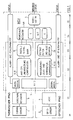
- Fig. 1 shows an overview of the signal processing in the detector, which can be divided into five stages S1 to S5.
- the first stage S1 consists of the sensor hardware and essentially contains a thermal sensor 1 formed by an NTC sensor, an optical sensor 2 formed by a light pulse transmitter and a light pulse receiver, a bias network 3 for the thermal sensor 1 and an ASIC 4.
- About the sensor -Hardware also includes an A / D converter 5 of a microcontroller MCU.
- the MCU has a ROM mask which contains the operating system and the sensor software of the detector and thus controls all processes at the functional level, that is to say the sensor control, the signal processing, and the addressing and communication with the control center.
- the ASIC 5 contains all amplifiers and filters for the signal of the light pulse receiver, a one-chip temperature sensor, the control electronics for the light pulse transmitter, a quartz oscillator and the start / power management as well as the line monitoring for the MCU. There is a bidirectional, serial data bus and various control lines between the MCU and the ASIC 4.
- the signals are processed in the second stage S2 following the A / D converter 5, with various compensations being used to try to obtain the most accurate possible representation of the real measurement variables.
- signal signatures or criteria are extracted, which are then condensed in the fourth stage S4 in a neural network NN to form a scalar hazard signal and are assigned to a hazard level.
- the decision about the definitive danger level is finally made in a verification stage 6 and forwarded together with the functional state or status to the communication interface of the MCU.
- the first three stages S1 to S3 are passed through separately from the signal from the thermal sensor 1 and from the signal from the optical sensor 2, which is symbolized in the figure by two signal paths, a "thermal” and an “optical” path, which are then combined in the fourth stage S4, that is to say in the neural network.
- the signal flow of the two paths through the stages S1 to S3 is shown in FIGS. 2a and 2b, and the neural network NN is shown in detail in FIG. 3.
- the thermal and then the optical signal path will now be described in more detail below:
- the NTC temperature sensor 1 is operated in a pulsed manner via the biasing network 3 and the NTC voltage is fed to the A / D converter 5.
- the NTC temperature data are subsequently analyzed in a stage 7, interruptions and short circuits being recognized.
- step 7 the influence of small driver voltage changes on the measured value is also compensated to increase the measuring accuracy. Any interference peaks are removed in the following “anti-EMI” algorithm 8. This limits the signal change from one measurement to the next to certain values stored in the data memory of the MCU. Normal fire signals pass this algorithm unchanged.
- the output signal of the A / D converter is then converted into a temperature value in an linearization stage 9 using an interpolation table in accordance with the characteristics of the NTC sensor. Then in a block 10 the heat dissipation through connecting wires and plastic wall and in a block 11 the Heat capacity of the NTC sensor 1 compensated.
- the output signals of blocks 10 and 11 then pass through a digital filter bank 12 and are finally linked in a stage 13 with parameters. At the output of stage 13 and thus at the end of the thermal path there are then several signature signals or criteria S1 to Sm which are dependent on the NTC signal and thus on the temperature.
- a pulse generator 14 which generates a current pulse of almost 100 ⁇ s every 3s, drives an infrared light-emitting diode 15 which forms the light pulse transmitter and sends a light pulse into the optical scattering space.
- the light scattered by any smoke is collected by a lens and directed to a receiver photodiode 15 '.
- the resulting photocurrent is integrated by an integrator 16 in synchronism with the transmission pulse.
- the subsequent, still differential voltage amplifier 17 offers several selectable gain settings.
- the coarse detector adjustment is then carried out.
- a so-called AMB filter 18 eliminates DC components and low-frequency interference from the signal. High-frequency interference has already been eliminated by integrator 17.
- a single unipolar signal appears at the output of the AMB filter 18 and is further amplified by a voltage amplifier 19.
- the output signal of the amplifier 19 is converted into digital data in the A / D converter 5, with which the software signal processing begins (FIG. 1, stage S2).
- the effective signal swing is now determined by forming the difference in a stage 20 between a light and a dark measurement. This arrives in a block 21 and, thanks to the availability of the ASIC temperature, can be corrected there in such a way that the temperature drops of the optoelectronic components are largely compensated for.
- the software-based fine adjustment which is also carried out in block 21, serves as the last and practically continuous adjustment of the signals to a desired size.
- tracking eliminates those signal components which are caused by very slow environmental influences (for example dustiness) and which would produce a false smoke signal over time and thus change the sensitivity.
- the result of the previous processing steps is a quantity that represents the effective, filtered, adjusted, temperature-compensated and updated smoke value and forms the immediate reference for determining the hazard level.
- the last link (block 23) in the optical signal processing are algorithms controlled by various parameter sets, which assess the temporal behavior of the variable representing the smoke value.
- the signature signals Sm + 1 to Sn are then available.
- the signature signals S1 to Sn of the thermal and the optical path form the input level L0 of a layered, neural network NN, which is shown in FIG. 3. It can be seen from the representation of the neural network NN in FIG. 1 that these input variables are dependent either on the temperature signal (T) or on the optical signal (O) or both.
- the network also has other levels L1 to L5 with so-called neurons or nodes.
- the input variables weighted with parameters are subjected to an addition and a maximum and / or minimum linkage. The addition takes place in the neurons labeled A and the maximum and / or minimum linkage in the neurons labeled M.
- the network can be integrated into a learning environment. Due to the learning effect of the network, certain connections will prove to be preferred and strengthen, and others will, at the same time, atrophy. Alternatively, the network can also be used without a learning phase be constructed. In both cases, the weights of the network are frozen during operation for security reasons.
- the hazard signal is assigned to one of several, for example at least three, security levels, and this signal assigned to one of the security levels is the output signal GS of the neural network NN.
- the shift of signal processing from the control center to the detectors and the use of a neural network for signal processing for detectors with multiple sensors is particularly advantageous, these multiple sensors should not be understood as restrictive.
- detectors with only one sensor can also be designed in the manner described.
- the neural network NN represents a very special type related to a fuzzy logic and could therefore also be replaced by a fuzzy logic.
Abstract
Description
Die vorliegende Erfindung betrifft eine Anordnung zur Früherkennung von Bränden, mit einer Mehrzahl von mit einer Zentrale verbundenen Meldern, von denen einige mit mindestens zwei Sensoren zur Überwachung von verschiedenen Brandkenngrössen ausgerüstet sind, und mit Mitteln zur Verarbeitung der Signale der Sensoren.The present invention relates to an arrangement for the early detection of fires, with a plurality of detectors connected to a control center, some of which are equipped with at least two sensors for monitoring different fire parameters, and with means for processing the signals from the sensors.
Da bei Meldern mit Mehrfachsensoren die einzelnen Sensoren verschiedene Parameter überwachen, kann das Antwortverhalten der Melder besser ausgeglichen und dadurch die Fehleralarmrate pro Detektionspunkt deutlich reduziert werden. Ausserdem steigt durch die mit der Mehrfachüberwachung verbundene Redundanz die Zuverlässigkeit und führt zu einem Ausgleich zwischen den bei Einfachdetektoren auftretenden schwachen und starken Punkten.As the individual sensors monitor different parameters in detectors with multiple sensors, the response behavior of the detectors can be better balanced and the error alarm rate per detection point can be significantly reduced. In addition, the redundancy associated with multiple monitoring increases reliability and leads to a balance between the weak and strong points that occur with single detectors.
Durch die Erfindung soll nun die Fehleralarmrate pro Detektionspunkt weiter reduziert und gleichzeitig eine möglichst frühzeitige Detektionsfähigkeit erhalten werden.The invention now aims to further reduce the error alarm rate per detection point and, at the same time, to obtain the earliest possible detection capability.
Diese Aufgabe wird erfindungsgemäss dadurch gelöst, dass die genannten Mittel zur Verarbeitung der Signale der Sensoren dezentral in den Meldern angeordnet sind und einen Microcontroller zur Aufbereitung der Sensorsignale und zur Signalverarbeitung zum Zweck der Gewinnung von Gefahrensignalen aufweisen, und dass die Gewinnung der Gefahrensignale in einem neuronalen Netzwerk erfolgt.This object is achieved according to the invention in that the means mentioned for processing the signals from the sensors are arranged decentrally in the detectors and have a microcontroller for processing the sensor signals and for signal processing for the purpose of obtaining hazard signals, and in that the hazard signals are obtained in a neuronal manner Network.
Bei der erfindungsgemässen Anordnung ist also die Signalverarbeitung von der Zentrale in die Melder verlagert und dezentralisiert, wodurch die Beschränkung der Kommunikationsbandbreite der üblichen Verbindungen zwischen Zentrale und Meldern ohne Einfluss ist. Ausserdem ist die Beobachtungslange der Signale keinen Einschränkungen unterworfen und die Möglichkeit einer Überlastung der Zentrale ist praktisch ausgeschlossen. Die hohe Redundanz des Systems hat ausserdem den Vorteil, dass bei Ausfall oder Störung des Hauptprozessors in der Zentrale die Melder selbst Alarm auslösen können.In the arrangement according to the invention, the signal processing is thus shifted from the control center into the detectors and is decentralized, as a result of which the limitation of the communication bandwidth of the usual connections between the control center and detectors has no influence. In addition, the observation length of the signals is not subject to any restrictions and the possibility of overloading the control center is practically excluded. The high redundancy of the system also has the The advantage that the detectors can trigger an alarm themselves if the main processor fails at the control center.
Die Verwendung des neuronalen Netzwerks hat den Vorteil, dass die Zuverlässigkeit der Melderfunktion ganz allgemein verbessert wird, indem eine breite Palette von Möglichkeiten der Verknüpfung der verschiedenen Signalsignaturen, das sind die Erkennungsmuster, besteht und in dem neuronalen Netzwerk auch optimal genutzt werden kann.The use of the neural network has the advantage that the reliability of the detector function is generally improved in that there is a wide range of possibilities for linking the different signal signatures, that is to say the detection patterns, and can also be optimally used in the neural network.
Im folgenden wird die Erfindung anhand eines Ausführungsbeispiels und der Zeichnungen näher erläutert; dabei zeigt:
- Fig. 1
- ein Übersichtsdiagramm der Signalverarbeitung im Melder,
- Fig. 2a, b
- ein Schema der beiden Signalpfade der Signalverarbeitung; und
- Fig. 3
- ein Diagramm des neuronalen Netzwerks der Signalverarbeitung.
- Fig. 1
- an overview diagram of signal processing in the detector,
- 2a, b
- a schematic of the two signal paths of signal processing; and
- Fig. 3
- a diagram of the neural network of signal processing.
Fig. 1 zeigt eine Übersicht der Signalverarbeitung im Melder, die in fünf Stufen S1 bis S5 aufgeteilt werden kann. Die erste Stufe S1 besteht aus der Sensor-Hardware und enthält im wesentlichen einen durch einen NTC-Sensor gebildeten Thermosensor 1, einen durch einen Lichtpulssender und einen Lichtpulsempfänger gebildeten optischen Sensor 2, ein Vorspannungsnetzwerk 3 für den Thermosensor 1 und einen ASIC 4. Zur Sensor-Hardware gehört ausserdem noch ein A/D-Wandler 5 eines Microcontrollers MCU.Fig. 1 shows an overview of the signal processing in the detector, which can be divided into five stages S1 to S5. The first stage S1 consists of the sensor hardware and essentially contains a
Die MCU weist in bekannter Weise eine ROM-Maske auf, die das Betriebssystem und die Sensorsoftware des Melders enthält und damit sämtliche Abläufe auf der Funktionsebene, also die Sensorsteuerung, die Signalverarbeitung sowie die Adressierung und die Kommunikation mit der Zentrale kontrolliert. Der ASIC 5 beinhaltet alle Verstärker und Filter für das Signal des Lichtimpulsempfängers, einen Einchip-Temperatursensor, die Ansteuerelektronik für den Lichtpulssender, einen Quarzoszillator und das Aufstart-/Power-Management sowie die Linienüberwachung für die MCU. Zwischen der MCU und dem ASIC 4 bestehen ein bidirektionaler, serieller Datenbus und diverse Kontrollleitungen.In a known manner, the MCU has a ROM mask which contains the operating system and the sensor software of the detector and thus controls all processes at the functional level, that is to say the sensor control, the signal processing, and the addressing and communication with the control center. The ASIC 5 contains all amplifiers and filters for the signal of the light pulse receiver, a one-chip temperature sensor, the control electronics for the light pulse transmitter, a quartz oscillator and the start / power management as well as the line monitoring for the MCU. There is a bidirectional, serial data bus and various control lines between the MCU and the ASIC 4.
In der an den A/D-Wandler 5 anschliessenden zweiten Stufe S2 werden die Signale aufbereitet, wobei durch verschiedene Kompensationen versucht wird, ein möglichst genaues Abbild der reellen Messgrössen zu erhalten. In der dritten Stufe S3 werden Signalsignaturen oder Kriterien extrahiert, die dann in der vierten Stufe S4 in einem neuronalen Netzwerk NN zu einem skalaren Gefahrensignal kondensiert und einer Gefahrenstufe zugeordnet werden. In der fünften Stufe S5 wird schliesslich in einer Verifizierungsstufe 6 der Entscheid über die definitive Gefahrenstufe gefällt und zusammen mit dem Funktionszustand oder Status an das Kommunikationsinterface der MCU weitergeleitet.The signals are processed in the second stage S2 following the A /
Gemäss Fig. 1 werden die ersten drei Stufen S1 bis S3 vom Signal des thermischen Sensors 1 und vom Signal des optischen Sensors 2 getrennt durchlaufen, was in der Figur durch zwei Signalpfade, einen "thermischen" und einen "optischen" Pfad, symbolisiert ist, die dann in der vierten Stufe S4, also im neuronalen Netzwerk zusammengeführt sind. Der Signalfluss der beiden Pfade durch die Stufen S1 bis S3 ist in den Fig. 2a und 2b, und das neuronale Netzwerk NN ist in Fig. 3 im Detail dargestellt.1, the first three stages S1 to S3 are passed through separately from the signal from the
Nachfolgend soll nun zuerst der thermische und dann der optische Signalpfad näher beschrieben werden: Der NTC-Temperatursensor 1 wird über das Vorspannungsnetzwerk 3 gepulst betrieben und die NTC-Spannung wird dem A/D-Wandler 5 zugeleitet. Die NTC-Temperaturdaten werden nachfolgend in einer Stufe 7 analysiert, wobei Unterbrechungen und Kurzschluss erkannt werden. In der Stufe 7 wird ausserdem zur Erhöhung der Messgenauigkeit der Einfluss von kleinen Treiberspannungsänderungen auf den Messwert kompensiert. Allfällige Störspitzen werden im nachfolgenden "anti-EMI"-Algorithmus 8 entfernt. Dieser begrenzt die Signaländerung von einer Messung zur nächsten auf bestimmte, im Datenspeicher der MCU gespeicherte Werte. Normale Brandsignale passieren diesen Algorithmus unverändert.The thermal and then the optical signal path will now be described in more detail below: The
Anschliessend wird in einer Linearisierungsstufe 9 das Ausgangssignal des A/D-Wandlers mittels einer Interpolationstabelle gemäss der Charakteristik des NTC-Sensors in einen Temperaturwert umgerechnet. Dann wird in einem Block 10 die Wärmeableitung durch Anschlussdrähte und Kunststoffwandung und in einem Block 11 die Wärmekapazität des NTC-Sensors 1 kompensiert. Die Ausgangssignale der Blöcke 10 und 11 durchlaufen dann eine digitale Filterbank 12 und werden schliesslich in einer Stufe 13 mit Parametern verknüpft. Am Ausgang der Stufe 13 und damit am Ende des thermischen Pfads stehen dann mehrere, vom NTC-Signal und damit von der Temperatur abhängige Signatursignale oder Kriterien S1 bis Sm zur Verfügung.The output signal of the A / D converter is then converted into a temperature value in an
Im optischen Signalpfad treibt ein Pulsgenerator 14, der alle 3s einen knapp 100µs langen Strompuls erzeugt, eine den Lichtimpulssender bildende Infrarot-Leuchtdiode 15, die einen Lichtpuls in den optischen Streuraum sendet. Das von allfällig vorhandenem Rauch gestreute Licht wird von einer Linse gesammelt und auf eine Empfänger-Photodiode 15' geleitet. Der resultierende Photostrom wird synchron zum Sendepuls von einem Integrator 16 integriert. Der nachfolgende, immer noch differentielle Spannungsverstärker 17 bietet mehrere wählbare Verstärkungseinstellungen an. Damit wird der Melder-Grobabgleich vorgenommen. Ein sogenanntes AMB-Filter 18 eliminiert Gleichstromanteile und niederfrequente Störungen aus dem Signal. Hochfrequente Störungen wurden bereits vom Integrator 17 beseitigt. Am Ausgang des AMB-Filters 18 erscheint ein einziges unipolares Signal, das von einem Spannungsverstärker 19 weiter verstärkt wird.In the optical signal path, a
Das Ausgangssignal des Verstärkers 19 wird im A/D-Wandler 5 in digitale Daten umgewandelt, womit die softwaremässige Signalverarbeitung beginnt (Fig. 1, Stufe S2). Durch Differenzbildung in einer Stufe 20 zwischen einer Hell- und einer Dunkelmessung wird jetzt der effektive Signalhub bestimmt. Dieser gelangt in einen Block 21 und kann dort dank der Verfügbarkeit der ASIC-Temperatur so korrigiert werden, dass eine weitgehende Kompensation der Temperaturabgänge der optoelektronischen Bauteile erfolgt. Als letzte und praktisch stufenlose Anpassung der Signale an eine Sollgrösse dient der softwaremässige Feinabgleich, der ebenfalls im Block 21 erfolgt. Im nächsten Block 22 beseitigt eine Nachführung diejenigen Signalanteile, die durch sehr langsame Umwelteinflüsse (beispielsweise Verstaubung) verursacht sind, und die mit der Zeit ein Scheinrauchsignal erzeugen und damit die Empfindlichkeit verändern würden.The output signal of the
Das Resultat aus den bisherigen Verarbeitungsschritten ist eine Grösse , die den effektiven, gefilterten, abgeglichenen, temperaturkompensierten und nachgeführten Rauchwert darstellt und die unmittelbare Referenz für die Ermittlung der Gefahrenstufe bildet. Als letztes Glied (Block 23) in der optischen Signalverarbeitung wirken von verschiedenen Parametersätzen gesteuerte Algorithmen, die das zeitliche Verhalten der den Rauchwert darstellenden Grösse beurteilen. Am Ende des optischen Signalverarbeitungspfades stehen dann die Signatursignale Sm+1 bis Sn zur Verfügung.The result of the previous processing steps is a quantity that represents the effective, filtered, adjusted, temperature-compensated and updated smoke value and forms the immediate reference for determining the hazard level. The last link (block 23) in the optical signal processing are algorithms controlled by various parameter sets, which assess the temporal behavior of the variable representing the smoke value. At the end of the optical signal processing path, the signature signals Sm + 1 to Sn are then available.
Die Signatursignale S1 bis Sn des thermischen und des optischen Pfades bilden die Eingangsebene L0 eines geschichteten, neuronalen Netzwerks NN, das in Fig. 3 dargestellt ist. Aus der Darstellung des neuronalen Netzwerks NN in Fig. 1 ist ersichtlich, dass diese Eingangsgrössen entweder vom Temperatursignal (T) abhängig sind, oder vom optischen Signal (O) oder von beiden. Das Netzwerk weist neben der Eingangsebene L0 noch weitere Ebenen L1 bis L5 mit sogenannten Neuronen oder Knoten auf. In diesen werden die mit Parametern gewichteten Eingangsgrössen einer Addition und einer Maximum- und/oder Minimumverknüpfung unterworfen. Die Addition erfolgt in den mit A und die Maximum- und/oder Minimumverknüpfung in den mit M bezeichneten Neuronen.The signature signals S1 to Sn of the thermal and the optical path form the input level L0 of a layered, neural network NN, which is shown in FIG. 3. It can be seen from the representation of the neural network NN in FIG. 1 that these input variables are dependent either on the temperature signal (T) or on the optical signal (O) or both. In addition to the input level L0, the network also has other levels L1 to L5 with so-called neurons or nodes. In these, the input variables weighted with parameters are subjected to an addition and a maximum and / or minimum linkage. The addition takes place in the neurons labeled A and the maximum and / or minimum linkage in the neurons labeled M.
Dabei ist die Maximumverknüpfung die nichtlineare Netzwerfunktion:
![]()
die nach dem Prinzip "alles gehört dem Stärksten" arbeitet.The maximum linkage is the nonlinear network function:
![]()
who works on the principle that "everything belongs to the strongest".
Die Addition ist das das Skalarprodukt:
![]()
Zwischen den Neuronen sind grundsätzlich alle Verbindungen möglich. In einer Lernphase während der Entwicklung des Melders kann das Netzwerk in eine Lernumgebung eingebunden werden. Dabei werden sich durch den Lerneffekt des Netzwerks bestimmte Verbindungen als bevorzugt erweisen und sich verstärken und andere werden gleichsam verkümmern. Alternativ kann das Netzwerk auch ohne Lernphase konstruiert werden. In beiden Fällen werden aus Sicherheitsgründen im Betrieb die Gewichte des Netzwerks eingefroren.The addition is the dot product:
![]()
In principle, all connections are possible between the neurons. In a learning phase during the development of the detector, the network can be integrated into a learning environment. Due to the learning effect of the network, certain connections will prove to be preferred and strengthen, and others will, at the same time, atrophy. Alternatively, the network can also be used without a learning phase be constructed. In both cases, the weights of the network are frozen during operation for security reasons.
Zwischen der Eingangs- und der Ausgangsebene L0 bzw. L5 des neuronalen Netzwerks NN erfolgt eine Konzentration der jeweiligen Eingangsgrössen auf eine einzige Ausgangsgrösse, die ein skalares Gefahrensignal darstellt. Das Gefahrensignal wird in einer Quantisierungsstufe 24 einer von mehreren, beispielsweise von mindestens drei, Gefahrenstufen zugeordnet, und dieses einer der Gefahrenstufen zugeordnete Signal ist das Ausgangssignal GS des neuronalen Netzwerks NN.Between the input and output levels L0 and L5 of the neural network NN, the respective input variables are concentrated on a single output variable, which represents a scalar danger signal. In a
Schliesslich erfolgt in der dem neuronalen Netzwerk nachgeordneten Verfifizierungsstufe 6 die Verifizierung der definitiven Gefahrenstufe. Das entsprechende Ausgangssignal GSdef wird zusammen mit dem Funktionszustand (Fig. 1, "Status") über das Kommunikationsinterface der MCU der Zentrale mitgeteilt.Finally, the verification of the final danger level takes place in the
Abschliessend sollen noch einige besonders vorteilhafte Eigenschaften und Zusatzfunktionen des beschriebenen Rauchmelders erwähnt werden:
- Die Messung der aktuellen ASIC-Temperatur mit Hilfe eines Einchip-Temperatursensors wurde bereits erwähnt. Diese Messung, die periodisch erfolgt, liefert einen Temperaturwert, mit dem die Temperaturgänge der optoelektronischen Bauteile softwaremässig kompensiert werde, so dass auch bei extremen Temperaturen zuverlässige Rauchdichtemessungen vorgenommen werden können.
- Die Funktionsweise der Signalnachführung wurde ebenfalls bereits erwähnt. Das Rauchdichtesignal wird von sehr niederfrequenten Anteilen befreit, um Einflüsse der Umwelt auszufiltern, die signifikant langsamer sind als Brandphänomene (beispielsweise Verstaubung). Damit wird eine sehr gute Langzeitkonstanz der Rauchempfindlichkeit erreicht.
- Regelmässig wird automatisch ein Selbsttest auf gewisse Fehler durchgeführt, der den Melder einer detaillierten Diagnose unterzieht.
- The measurement of the current ASIC temperature using a single-chip temperature sensor has already been mentioned. This measurement, which is carried out periodically, provides a temperature value with which the temperature responses of the optoelectronic components are compensated for by software, so that reliable smoke density measurements can also be carried out at extreme temperatures.
- The functionality of signal tracking has also already been mentioned. The smoke density signal is freed from very low-frequency components in order to filter out environmental influences that are significantly slower than fire phenomena (e.g. dustiness). This ensures a very good long-term consistency in smoke sensitivity.
- A self-test for certain errors is carried out automatically, which subjects the detector to a detailed diagnosis.
Wenn auch die Verlagerung der Signalverarbeitung von der Zentrale in die Melder und die Verwendung eines neuronalen Netzwerks bei der Signalverarbeitung für Melder mit Mehrfachsensoren besonders vorteilhaft ist, so sollen diese Mehrfachsensoren nicht als einschränkend verstanden werden. Selbstverständlich können auch Melder mit nur einem Sensor in der beschriebenen Art ausgebildet sein. Ausserdem sei noch erwähnt, dass das neuronale Netzwerk NN einen ganz speziellen, einer Fuzzy-Logic verwandten Typus darstellt und daher auch durch eine Fuzzy-Logic ersetzt werden könnte.Although the shift of signal processing from the control center to the detectors and the use of a neural network for signal processing for detectors with multiple sensors is particularly advantageous, these multiple sensors should not be understood as restrictive. Of course, detectors with only one sensor can also be designed in the manner described. It should also be mentioned that the neural network NN represents a very special type related to a fuzzy logic and could therefore also be replaced by a fuzzy logic.
Ein ganz wesentliches Merkmal der vorliegenden Anordnung ist durch die digitale Filterbank 12 und den Block 23 (Fig. 1) gebildet, wobei insbesondere die digitale Filterbank rekursive Filter enthalten kann. Wenn man anstelle dieser Filterbank und/oder des Blocks 23 je ein neuronales Netzwerk verwenden und diesem Zeitmuster der Sensorsignale sequentiell zuführen würde, dann hätte man gegenüber der vorgeschlagenen Lösung zwei wesentliche Nachteile:
- Diese neuronalen Netzwerke wären eine Art von Transversalfilter und hätten ein wesentlich geringeres Gedächtnis als rekursive Filter;
- am Ausgang jedes dieser neuronalen Netzwerke wäre nur je eine Signalsignatur pro Brandphänomen (Rauch, Temperatur) erhältlich, wogegen die vorgeschlagene Lösung S1 bis Sm Signalsignaturen für das Brandphänomen Temperatur und Sm+1 bis Sn Signalsignaturen für das Brandphänomen Rauch zur Verfügung stellt. Diese Mehrzahl von Signalsignaturen ist aber für die sichere Funktion des neuronalen Netzwerks NN (Fig. 3) sehr wichtig, weil man dieses dann so ausbilden kann, dass seine Funktionen voll verständlich und überblickbar sind. Und letzteres ist in einem Sicherheitssystem unbedingt erforderlich.
- These neural networks would be a type of transversal filter and would have a much smaller memory than recursive filters;
- at the output of each of these neural networks, only one signal signature per fire phenomenon (smoke, temperature) would be available, whereas the proposed solution S1 to Sm provides signal signatures for the temperature fire phenomenon and Sm + 1 to Sn signal signatures for the smoke fire phenomenon. However, this plurality of signal signatures is very important for the safe functioning of the neural network NN (FIG. 3), because it can then be designed in such a way that its functions are fully understandable and clear. And the latter is absolutely essential in a security system.
Claims (17)
Applications Claiming Priority (3)
| Application Number | Priority Date | Filing Date | Title |
|---|---|---|---|
| CH3479/93 | 1993-11-22 | ||
| CH347993 | 1993-11-22 | ||
| CH03479/93A CH686913A5 (en) | 1993-11-22 | 1993-11-22 | Arrangement for early detection of fires. |
Publications (2)
| Publication Number | Publication Date |
|---|---|
| EP0654770A1 true EP0654770A1 (en) | 1995-05-24 |
| EP0654770B1 EP0654770B1 (en) | 2000-02-02 |
Family
ID=4256867
Family Applications (1)
| Application Number | Title | Priority Date | Filing Date |
|---|---|---|---|
| EP94113869A Expired - Lifetime EP0654770B1 (en) | 1993-11-22 | 1994-09-05 | Device for early detection of fires |
Country Status (10)
| Country | Link |
|---|---|
| US (1) | US5751209A (en) |
| EP (1) | EP0654770B1 (en) |
| JP (1) | JPH07192189A (en) |
| CN (1) | CN1052087C (en) |
| AT (1) | ATE189549T1 (en) |
| CH (1) | CH686913A5 (en) |
| DE (1) | DE59409119D1 (en) |
| DK (1) | DK0654770T3 (en) |
| ES (1) | ES2144474T3 (en) |
| PT (1) | PT654770E (en) |
Cited By (8)
| Publication number | Priority date | Publication date | Assignee | Title |
|---|---|---|---|---|
| EP0729123A1 (en) * | 1995-02-21 | 1996-08-28 | Pittway Corporation | Apparatus including a fire sensor and a non-fire sensor |
| EP0759602A1 (en) | 1995-08-23 | 1997-02-26 | Cerberus Ag | Fire detector |
| WO2000014693A1 (en) * | 1998-09-09 | 2000-03-16 | Siemens Building Technologies Ag | Fire alarm and fire alarm system |
| EP1768074A1 (en) | 2005-09-21 | 2007-03-28 | Siemens Schweiz AG | Early detection of fires |
| US7286704B2 (en) | 2000-03-09 | 2007-10-23 | Robert Bosch Gmbh | Imaging fire detector |
| CN104933841A (en) * | 2015-04-30 | 2015-09-23 | 重庆三峡学院 | Fire prediction method based on self-organizing neural network |
| EP3531386A4 (en) * | 2016-10-24 | 2020-09-30 | Hochiki Corporation | Fire monitoring system |
| EP2091029B2 (en) † | 2008-02-15 | 2020-11-18 | Siemens Schweiz AG | Hazard recognition utilising a temperature measurement device integrated in a microcontroller |
Families Citing this family (21)
| Publication number | Priority date | Publication date | Assignee | Title |
|---|---|---|---|---|
| DE19902319B4 (en) * | 1999-01-21 | 2011-06-30 | Novar GmbH, Albstadt-Ebingen Zweigniederlassung Neuss, 41469 | Scattered light fire detectors |
| DE19932906A1 (en) * | 1999-07-12 | 2001-01-18 | Siemens Ag | Method and arrangement for detecting a heat source in a monitored area |
| US6493687B1 (en) * | 1999-12-18 | 2002-12-10 | Detection Systems, Inc. | Apparatus and method for detecting glass break |
| US6184792B1 (en) | 2000-04-19 | 2001-02-06 | George Privalov | Early fire detection method and apparatus |
| US7034701B1 (en) * | 2000-06-16 | 2006-04-25 | The United States Of America As Represented By The Secretary Of The Navy | Identification of fire signatures for shipboard multi-criteria fire detection systems |
| PT102617B (en) | 2001-05-30 | 2004-01-30 | Inst Superior Tecnico | COMPUTER-CONTROLLED LIDAR SYSTEM FOR SMOKING LOCATION, APPLICABLE, IN PARTICULAR, TO EARLY DETECTION OF FIREFIGHTERS |
| FR2831981B1 (en) * | 2001-11-08 | 2005-07-08 | Cit Alcatel | METHOD AND DEVICE FOR ANALYZING ALARMS FROM A COMMUNICATION NETWORK |
| WO2005045775A1 (en) * | 2003-11-07 | 2005-05-19 | Axonx, L.L.C. | Smoke detection method and apparatus |
| US7680297B2 (en) * | 2004-05-18 | 2010-03-16 | Axonx Fike Corporation | Fire detection method and apparatus |
| US7202794B2 (en) * | 2004-07-20 | 2007-04-10 | General Monitors, Inc. | Flame detection system |
| US8248226B2 (en) | 2004-11-16 | 2012-08-21 | Black & Decker Inc. | System and method for monitoring security at a premises |
| US7769204B2 (en) * | 2006-02-13 | 2010-08-03 | George Privalov | Smoke detection method and apparatus |
| WO2008088325A1 (en) * | 2007-01-16 | 2008-07-24 | Utc Fire & Security Corporation | System and method for video based fire detection |
| US8378808B1 (en) | 2007-04-06 | 2013-02-19 | Torrain Gwaltney | Dual intercom-interfaced smoke/fire detection system and associated method |
| US7786880B2 (en) * | 2007-06-01 | 2010-08-31 | Honeywell International Inc. | Smoke detector |
| US7986228B2 (en) | 2007-09-05 | 2011-07-26 | Stanley Convergent Security Solutions, Inc. | System and method for monitoring security at a premises using line card |
| CN104008625A (en) * | 2014-05-21 | 2014-08-27 | 关宏 | Intelligent fire evacuation system achieving evacuation through images |
| EP3704679A1 (en) * | 2017-10-30 | 2020-09-09 | Carrier Corporation | Compensator in a detector device |
| EP3796985A4 (en) * | 2018-05-21 | 2022-03-16 | Tyco Fire Products LP | Systems and methods of real-time electronic fire sprinkler location and activation |
| US11361654B2 (en) * | 2020-08-19 | 2022-06-14 | Honeywell International Inc. | Operating a fire system network |
| CN114333251B (en) * | 2021-12-29 | 2023-06-20 | 成都中科慧源科技有限公司 | Intelligent alarm, method, system, equipment and storage medium |
Citations (2)
| Publication number | Priority date | Publication date | Assignee | Title |
|---|---|---|---|---|
| EP0338218A1 (en) * | 1988-03-30 | 1989-10-25 | Cerberus Ag | Early fire detection method |
| EP0403659A1 (en) * | 1988-12-02 | 1990-12-27 | Nohmi Bosai Kabushiki Kaisha | Fire alarm system |
Family Cites Families (8)
| Publication number | Priority date | Publication date | Assignee | Title |
|---|---|---|---|---|
| US3099825A (en) * | 1960-09-30 | 1963-07-30 | Harriman Cy | Control units for fire protective signaling systems |
| US3703721A (en) * | 1971-06-01 | 1972-11-21 | Audio Alert Corp | Fire alarm system |
| US4027302A (en) * | 1976-06-03 | 1977-05-31 | W. E. Healey & Associates, Inc. | Double detection circuit for conserving energy in fire detection systems and the like |
| US4319229A (en) * | 1980-06-09 | 1982-03-09 | Firecom, Inc. | Alarm system having plural diverse detection means |
| JPS58127292A (en) * | 1982-01-26 | 1983-07-29 | ニツタン株式会社 | Fire sensing system |
| US4633230A (en) * | 1984-05-04 | 1986-12-30 | Tam Wee M | Cooking, fire, and burglar alarm system |
| JPH0778484B2 (en) * | 1986-05-16 | 1995-08-23 | 株式会社日立製作所 | Air-fuel ratio sensor temperature controller |
| IT225152Z2 (en) * | 1990-11-05 | 1996-10-22 | G P B Beghelli S R L Ora Begne | IMPROVEMENT IN EMERGENCY LAMPS, ESPECIALLY OF THE PORTABLE TYPE, PROVIDED WITH A SENSOR OF A GAS AND / OR HARMFUL COMBUSION SMOKE. |
-
1993
- 1993-11-22 CH CH03479/93A patent/CH686913A5/en not_active IP Right Cessation
-
1994
- 1994-09-05 DK DK94113869T patent/DK0654770T3/en active
- 1994-09-05 DE DE59409119T patent/DE59409119D1/en not_active Expired - Lifetime
- 1994-09-05 AT AT94113869T patent/ATE189549T1/en active
- 1994-09-05 PT PT94113869T patent/PT654770E/en unknown
- 1994-09-05 EP EP94113869A patent/EP0654770B1/en not_active Expired - Lifetime
- 1994-09-05 ES ES94113869T patent/ES2144474T3/en not_active Expired - Lifetime
- 1994-09-20 JP JP6225006A patent/JPH07192189A/en active Pending
- 1994-11-20 US US08/345,735 patent/US5751209A/en not_active Expired - Lifetime
- 1994-11-22 CN CN94118504A patent/CN1052087C/en not_active Expired - Lifetime
Patent Citations (2)
| Publication number | Priority date | Publication date | Assignee | Title |
|---|---|---|---|---|
| EP0338218A1 (en) * | 1988-03-30 | 1989-10-25 | Cerberus Ag | Early fire detection method |
| EP0403659A1 (en) * | 1988-12-02 | 1990-12-27 | Nohmi Bosai Kabushiki Kaisha | Fire alarm system |
Non-Patent Citations (1)
| Title |
|---|
| SHINJI NAKANISHI: "INTELLIGENT FIRE WARNING SYSTEM APPLYING FUZZY THEORY", PROCEEDINGS OF IECON 91. 1991INTERNATIONAL CONFERENCE ON INDUSTRIAL ELECTRONICS, CONTROL AND INSTRUMENTATION, vol. 2, 1 November 1991 (1991-11-01), KOBE,JAPAN, pages 1561 - 1566, XP000313493 * |
Cited By (9)
| Publication number | Priority date | Publication date | Assignee | Title |
|---|---|---|---|---|
| EP0729123A1 (en) * | 1995-02-21 | 1996-08-28 | Pittway Corporation | Apparatus including a fire sensor and a non-fire sensor |
| US5659292A (en) * | 1995-02-21 | 1997-08-19 | Pittway Corporation | Apparatus including a fire sensor and a non-fire sensor |
| EP0759602A1 (en) | 1995-08-23 | 1997-02-26 | Cerberus Ag | Fire detector |
| WO2000014693A1 (en) * | 1998-09-09 | 2000-03-16 | Siemens Building Technologies Ag | Fire alarm and fire alarm system |
| US7286704B2 (en) | 2000-03-09 | 2007-10-23 | Robert Bosch Gmbh | Imaging fire detector |
| EP1768074A1 (en) | 2005-09-21 | 2007-03-28 | Siemens Schweiz AG | Early detection of fires |
| EP2091029B2 (en) † | 2008-02-15 | 2020-11-18 | Siemens Schweiz AG | Hazard recognition utilising a temperature measurement device integrated in a microcontroller |
| CN104933841A (en) * | 2015-04-30 | 2015-09-23 | 重庆三峡学院 | Fire prediction method based on self-organizing neural network |
| EP3531386A4 (en) * | 2016-10-24 | 2020-09-30 | Hochiki Corporation | Fire monitoring system |
Also Published As
| Publication number | Publication date |
|---|---|
| DK0654770T3 (en) | 2000-07-17 |
| CN1052087C (en) | 2000-05-03 |
| ATE189549T1 (en) | 2000-02-15 |
| JPH07192189A (en) | 1995-07-28 |
| CN1122486A (en) | 1996-05-15 |
| DE59409119D1 (en) | 2000-03-09 |
| ES2144474T3 (en) | 2000-06-16 |
| EP0654770B1 (en) | 2000-02-02 |
| PT654770E (en) | 2000-07-31 |
| CH686913A5 (en) | 1996-07-31 |
| US5751209A (en) | 1998-05-12 |
Similar Documents
| Publication | Publication Date | Title |
|---|---|---|
| EP0654770B1 (en) | Device for early detection of fires | |
| DE60014709T2 (en) | TWO-WIRE TRANSMITTER WITH SELF-TESTING AND LOW POWER | |
| DE69737336T2 (en) | Validity checking sensors | |
| DE10297009B4 (en) | Sensor fusion using self-evaluating process sensors | |
| DE4436658B4 (en) | Device and method for troubleshooting | |
| DE3610466C2 (en) | ||
| DE3614140C2 (en) | ||
| DE3418622C2 (en) | ||
| DE69818275T2 (en) | QUALITY MEASUREMENT OF WELDING | |
| EP0173833B1 (en) | Circuit and process to measure and to digitize a resistor | |
| DE102009061036B4 (en) | Residue generation apparatus and method for detecting erroneous transients, drifts or oscillations in the system behavior of a system of an aircraft, and aircraft | |
| DE10140134A1 (en) | Multi-sensor detector e.g. for detecting gas quality to detect fire state, delivers information relating to ambient states via data communication medium | |
| EP1860410A1 (en) | Method for processing the output signal of a transducer and force measuring device | |
| EP0788624B1 (en) | Process for analysing a measurement and measurement analyser for implementing it | |
| WO2006037804A1 (en) | Scattered light smoke detector | |
| DE19952327B4 (en) | Fire sensor and method for detecting a fire | |
| EP1736748A1 (en) | Method of processing the output signal of a mesuring transducer and force measuring device for carrying out the method. | |
| EP0750764B1 (en) | Process and arrangement for fuzzy control | |
| EP0231786A2 (en) | Process for eliminating disturbances in measuring signals | |
| DE3506956A1 (en) | SMOKE DETECTOR | |
| DE19625896A1 (en) | Warning of impending failure in auto-calibration system of e.g. gas analysis instruments | |
| EP0707247B1 (en) | Analyzer, in particular for waste water | |
| EP0660282B1 (en) | System for the early detection of fires | |
| DE3010324C2 (en) | ||
| WO1997028521A1 (en) | Device for the production of an alarm and for surveillance of an area |
Legal Events
| Date | Code | Title | Description |
|---|---|---|---|
| PUAI | Public reference made under article 153(3) epc to a published international application that has entered the european phase |
Free format text: ORIGINAL CODE: 0009012 |
|
| AK | Designated contracting states |
Kind code of ref document: A1 Designated state(s): AT BE CH DE DK ES FR GB IE IT LI LU NL PT SE |
|
| 17P | Request for examination filed |
Effective date: 19951115 |
|
| 17Q | First examination report despatched |
Effective date: 19980421 |
|
| GRAG | Despatch of communication of intention to grant |
Free format text: ORIGINAL CODE: EPIDOS AGRA |
|
| RAP1 | Party data changed (applicant data changed or rights of an application transferred) |
Owner name: SIEMENS BUILDING TECHNOLOGIES AG |
|
| GRAG | Despatch of communication of intention to grant |
Free format text: ORIGINAL CODE: EPIDOS AGRA |
|
| GRAH | Despatch of communication of intention to grant a patent |
Free format text: ORIGINAL CODE: EPIDOS IGRA |
|
| GRAH | Despatch of communication of intention to grant a patent |
Free format text: ORIGINAL CODE: EPIDOS IGRA |
|
| GRAA | (expected) grant |
Free format text: ORIGINAL CODE: 0009210 |
|
| AK | Designated contracting states |
Kind code of ref document: B1 Designated state(s): AT BE CH DE DK ES FR GB IE IT LI LU NL PT SE |
|
| REF | Corresponds to: |
Ref document number: 189549 Country of ref document: AT Date of ref document: 20000215 Kind code of ref document: T |
|
| REG | Reference to a national code |
Ref country code: CH Ref legal event code: EP |
|
| GBT | Gb: translation of ep patent filed (gb section 77(6)(a)/1977) |
Effective date: 20000202 |
|
| REF | Corresponds to: |
Ref document number: 59409119 Country of ref document: DE Date of ref document: 20000309 |
|
| ITF | It: translation for a ep patent filed |
Owner name: JACOBACCI & PERANI S.P.A. |
|
| REG | Reference to a national code |
Ref country code: IE Ref legal event code: FG4D Free format text: GERMAN |
|
| REG | Reference to a national code |
Ref country code: ES Ref legal event code: FG2A Ref document number: 2144474 Country of ref document: ES Kind code of ref document: T3 |
|
| REG | Reference to a national code |
Ref country code: DK Ref legal event code: T3 |
|
| REG | Reference to a national code |
Ref country code: PT Ref legal event code: SC4A Free format text: AVAILABILITY OF NATIONAL TRANSLATION Effective date: 20000428 |
|
| PLBE | No opposition filed within time limit |
Free format text: ORIGINAL CODE: 0009261 |
|
| STAA | Information on the status of an ep patent application or granted ep patent |
Free format text: STATUS: NO OPPOSITION FILED WITHIN TIME LIMIT |
|
| 26N | No opposition filed | ||
| REG | Reference to a national code |
Ref country code: GB Ref legal event code: IF02 |
|
| REG | Reference to a national code |
Ref country code: CH Ref legal event code: PFA Owner name: SIEMENS BUILDING TECHNOLOGIES AG C-IPR Free format text: SIEMENS BUILDING TECHNOLOGIES AG#ALTE LANDSTRASSE 411#8708 MAENNEDORF (CH) -TRANSFER TO- SIEMENS BUILDING TECHNOLOGIES AG C-IPR#GUBELSTRASSE 22#6300 ZUG (CH) |
|
| PGFP | Annual fee paid to national office [announced via postgrant information from national office to epo] |
Ref country code: DK Payment date: 20070910 Year of fee payment: 14 |
|
| PGFP | Annual fee paid to national office [announced via postgrant information from national office to epo] |
Ref country code: LU Payment date: 20070911 Year of fee payment: 14 |
|
| REG | Reference to a national code |
Ref country code: PT Ref legal event code: PC4A Owner name: SIEMENS SCHWEIZ AG, US Effective date: 20080829 |
|
| REG | Reference to a national code |
Ref country code: PT Ref legal event code: PC4A Owner name: SIEMENS AKTIENGESELLSCHAFT, DE Effective date: 20080829 |
|
| REG | Reference to a national code |
Ref country code: FR Ref legal event code: TP Ref country code: FR Ref legal event code: CD |
|
| REG | Reference to a national code |
Ref country code: CH Ref legal event code: PUE Owner name: SIEMENS AKTIENGESELLSCHAFT Free format text: SIEMENS BUILDING TECHNOLOGIES AG C-IPR#GUBELSTRASSE 22#6300 ZUG (CH) -TRANSFER TO- SIEMENS AKTIENGESELLSCHAFT#WITTELSBACHERPLATZ 2#80333 MUENCHEN (DE) Ref country code: CH Ref legal event code: NV Representative=s name: SIEMENS SCHWEIZ AG |
|
| REG | Reference to a national code |
Ref country code: DK Ref legal event code: EBP |
|
| REG | Reference to a national code |
Ref country code: GB Ref legal event code: 732E Free format text: REGISTERED BETWEEN 20090514 AND 20090520 |
|
| BECA | Be: change of holder's address |
Owner name: SIEMENS A.G.WITTELSBACHERPLATZ 2, DE-80333 MUENCHE Effective date: 20100423 |
|
| BECH | Be: change of holder |
Owner name: SIEMENS A.G. Effective date: 20100423 |
|
| PG25 | Lapsed in a contracting state [announced via postgrant information from national office to epo] |
Ref country code: DK Free format text: LAPSE BECAUSE OF NON-PAYMENT OF DUE FEES Effective date: 20090331 |
|
| PG25 | Lapsed in a contracting state [announced via postgrant information from national office to epo] |
Ref country code: LU Free format text: LAPSE BECAUSE OF NON-PAYMENT OF DUE FEES Effective date: 20080905 |
|
| REG | Reference to a national code |
Ref country code: NL Ref legal event code: SD Effective date: 20110318 |
|
| PGFP | Annual fee paid to national office [announced via postgrant information from national office to epo] |
Ref country code: IE Payment date: 20110923 Year of fee payment: 18 |
|
| PGFP | Annual fee paid to national office [announced via postgrant information from national office to epo] |
Ref country code: AT Payment date: 20110810 Year of fee payment: 18 Ref country code: PT Payment date: 20110825 Year of fee payment: 18 Ref country code: SE Payment date: 20110908 Year of fee payment: 18 |
|
| PGFP | Annual fee paid to national office [announced via postgrant information from national office to epo] |
Ref country code: IT Payment date: 20110927 Year of fee payment: 18 Ref country code: NL Payment date: 20110913 Year of fee payment: 18 |
|
| PGFP | Annual fee paid to national office [announced via postgrant information from national office to epo] |
Ref country code: ES Payment date: 20111013 Year of fee payment: 18 Ref country code: BE Payment date: 20111013 Year of fee payment: 18 |
|
| REG | Reference to a national code |
Ref country code: PT Ref legal event code: MM4A Free format text: LAPSE DUE TO NON-PAYMENT OF FEES Effective date: 20130305 |
|
| BERE | Be: lapsed |
Owner name: SIEMENS A.G. Effective date: 20120930 |
|
| REG | Reference to a national code |
Ref country code: NL Ref legal event code: V1 Effective date: 20130401 |
|
| PG25 | Lapsed in a contracting state [announced via postgrant information from national office to epo] |
Ref country code: SE Free format text: LAPSE BECAUSE OF NON-PAYMENT OF DUE FEES Effective date: 20120906 |
|
| REG | Reference to a national code |
Ref country code: SE Ref legal event code: EUG |
|
| REG | Reference to a national code |
Ref country code: AT Ref legal event code: MM01 Ref document number: 189549 Country of ref document: AT Kind code of ref document: T Effective date: 20120905 |
|
| PG25 | Lapsed in a contracting state [announced via postgrant information from national office to epo] |
Ref country code: PT Free format text: LAPSE BECAUSE OF NON-PAYMENT OF DUE FEES Effective date: 20130305 |
|
| REG | Reference to a national code |
Ref country code: IE Ref legal event code: MM4A |
|
| PG25 | Lapsed in a contracting state [announced via postgrant information from national office to epo] |
Ref country code: AT Free format text: LAPSE BECAUSE OF NON-PAYMENT OF DUE FEES Effective date: 20120905 Ref country code: BE Free format text: LAPSE BECAUSE OF NON-PAYMENT OF DUE FEES Effective date: 20120930 Ref country code: IE Free format text: LAPSE BECAUSE OF NON-PAYMENT OF DUE FEES Effective date: 20120905 |
|
| PG25 | Lapsed in a contracting state [announced via postgrant information from national office to epo] |
Ref country code: NL Free format text: LAPSE BECAUSE OF NON-PAYMENT OF DUE FEES Effective date: 20130401 Ref country code: IT Free format text: LAPSE BECAUSE OF NON-PAYMENT OF DUE FEES Effective date: 20120905 |
|
| REG | Reference to a national code |
Ref country code: ES Ref legal event code: FD2A Effective date: 20131018 |
|
| PG25 | Lapsed in a contracting state [announced via postgrant information from national office to epo] |
Ref country code: ES Free format text: LAPSE BECAUSE OF NON-PAYMENT OF DUE FEES Effective date: 20120906 |
|
| PGFP | Annual fee paid to national office [announced via postgrant information from national office to epo] |
Ref country code: FR Payment date: 20130924 Year of fee payment: 20 Ref country code: GB Payment date: 20130911 Year of fee payment: 20 |
|
| PGFP | Annual fee paid to national office [announced via postgrant information from national office to epo] |
Ref country code: CH Payment date: 20131210 Year of fee payment: 20 Ref country code: DE Payment date: 20131120 Year of fee payment: 20 |
|
| REG | Reference to a national code |
Ref country code: DE Ref legal event code: R071 Ref document number: 59409119 Country of ref document: DE |
|
| REG | Reference to a national code |
Ref country code: CH Ref legal event code: PL |
|
| REG | Reference to a national code |
Ref country code: GB Ref legal event code: PE20 Expiry date: 20140904 |
|
| PG25 | Lapsed in a contracting state [announced via postgrant information from national office to epo] |
Ref country code: DE Free format text: LAPSE BECAUSE OF EXPIRATION OF PROTECTION Effective date: 20140906 |
|
| PG25 | Lapsed in a contracting state [announced via postgrant information from national office to epo] |
Ref country code: GB Free format text: LAPSE BECAUSE OF EXPIRATION OF PROTECTION Effective date: 20140904 |