EP0654673A1 - Method and apparatus for insulation monitoring in unearthed DC and AC networks - Google Patents
Method and apparatus for insulation monitoring in unearthed DC and AC networks Download PDFInfo
- Publication number
- EP0654673A1 EP0654673A1 EP94118162A EP94118162A EP0654673A1 EP 0654673 A1 EP0654673 A1 EP 0654673A1 EP 94118162 A EP94118162 A EP 94118162A EP 94118162 A EP94118162 A EP 94118162A EP 0654673 A1 EP0654673 A1 EP 0654673A1
- Authority
- EP
- European Patent Office
- Prior art keywords
- measurement
- value
- network
- voltage
- measuring
- Prior art date
- Legal status (The legal status is an assumption and is not a legal conclusion. Google has not performed a legal analysis and makes no representation as to the accuracy of the status listed.)
- Granted
Links
Images

Classifications
-
- G—PHYSICS
- G01—MEASURING; TESTING
- G01R—MEASURING ELECTRIC VARIABLES; MEASURING MAGNETIC VARIABLES
- G01R27/00—Arrangements for measuring resistance, reactance, impedance, or electric characteristics derived therefrom
- G01R27/02—Measuring real or complex resistance, reactance, impedance, or other two-pole characteristics derived therefrom, e.g. time constant
- G01R27/16—Measuring impedance of element or network through which a current is passing from another source, e.g. cable, power line
- G01R27/18—Measuring resistance to earth, i.e. line to ground
-
- G—PHYSICS
- G01—MEASURING; TESTING
- G01R—MEASURING ELECTRIC VARIABLES; MEASURING MAGNETIC VARIABLES
- G01R27/00—Arrangements for measuring resistance, reactance, impedance, or electric characteristics derived therefrom
- G01R27/02—Measuring real or complex resistance, reactance, impedance, or other two-pole characteristics derived therefrom, e.g. time constant
- G01R27/025—Measuring very high resistances, e.g. isolation resistances, i.e. megohm-meters
-
- G—PHYSICS
- G01—MEASURING; TESTING
- G01R—MEASURING ELECTRIC VARIABLES; MEASURING MAGNETIC VARIABLES
- G01R31/00—Arrangements for testing electric properties; Arrangements for locating electric faults; Arrangements for electrical testing characterised by what is being tested not provided for elsewhere
- G01R31/50—Testing of electric apparatus, lines, cables or components for short-circuits, continuity, leakage current or incorrect line connections
- G01R31/52—Testing for short-circuits, leakage current or ground faults
Definitions
- the invention relates to a method for monitoring the insulation of unearthed direct and alternating current networks according to the preamble of claim 1 and a device suitable for carrying out this method according to the preamble of claim 21.
- the invention is concerned with the insulation monitoring of unearthed direct current networks and alternating current networks in operation and in particular also of those alternating current networks in which leakage direct currents and low and high-frequency components occur due to connected direct current, alternating current or other power converters which occur via the unavoidable ohmic part of the Insulation resistance between the mains and earth flow.
- the ohmic part of the insulation resistance of the network can be measured during operation by superimposing a constant DC measurement voltage on the network via an ohmic network connection between the network and earth.
- the due this DC measuring voltage via the network coupling, the network and the ohmic insulation resistance, the measurement DC current flowing is proportional in size to the size of the ohmic insulation resistance, so that this resistance can be determined from the DC measurement current or a measurement current measurement value derived therefrom, such as a voltage.
- Interfering frequency influences can be filtered out by a low-pass filter.
- a direct current interference component based on a leakage direct current is added (or subtracted) to the measurement direct current, which leads to incorrect measurements when using a measurement direct voltage.
- an alternating pulse voltage with different pulse voltage values can be superimposed on the network instead of a DC measurement voltage.
- the respective measured current measured value is always only recorded after the network has settled to the respective pulse voltage value. The ohmic insulation resistance is then determined from the difference between two successive measured current measured values. The influence of the interference component is eliminated by forming the difference.
- the present invention is therefore based on the object of designing a method for monitoring the insulation of ungrounded direct and alternating current networks according to the preamble of claim 1 and a device suitable for carrying out this method according to the preamble of claim 21 so that it is easy to handle and with Simple measures to achieve shorter measuring times with any unearthed networks while avoiding measurement falsifications.
- a method for monitoring the insulation of unearthed direct and alternating current networks of the type mentioned in the preamble of claim 1 is distinguished according to the invention by the features listed in the characterizing part of this claim.
- the individual pulses of the pulse alternating voltage are thus always adapted in terms of their length to the respective existing network so that the next pulse voltage value is immediately switched over when the continuously monitored transient process has ended.
- This results in a constant adaptation of the measuring method to the current network conditions, so that optimally short measuring times can be achieved without any risk of incorrect measurements.
- the measurement result of the ohmic insulation resistance can be achieved using the new method after a measurement time which, depending on the size of the ohmic and capacitive parts of the insulation resistance, is only about 10% in the optimal case.
- the time intervals of the measuring times or the lengths of the mean value measuring intervals should become larger over time when monitoring each transient process. This is to prevent the monitoring process from being terminated prematurely because differences in the measurement samples which are too small and no longer readily measurable occur.
- By increasing the time intervals or measuring intervals it is achieved that there are always sufficiently large measurement sample differences during the transient process and thus the end of the transient process can be reliably detected.
- a starting value that is as small as possible should initially be selected, which, in the most unfavorable grid conditions, that is to say with a large time constant, just enables the measuring process to be reliably determined.
- the starting values of the measurement sample time interval or the mean value measurement interval can be selected in accordance with the regulations of claims 6 to 8, taking into account the respective network conditions.
- the enlargement of the measurement samples - time intervals or the average measurement intervals, which takes place during the monitoring of each transient process, should preferably be carried out in accordance with the regulations of claims 9 to 11 in order to simplify the method and to achieve perfect measurement results. According to claims 10 and 11 it can be achieved that the monitoring process does not end at a maximum measuring resolution of approximately 1% before the approx. 6-fold time constant of the transient process is reached, that is to say it is not terminated too early.
- claim 12 increases the measurement reliability and switches off incorrect measurements, for example those due to changing network conditions.
- very favorable conditions for averaging can be achieved by reducing the initially assumed interference frequency for determining the respective starting value of the mean value measuring interval within a certain limit when no clear measuring result can be achieved until a reliable measurement result is available. For the next measurement cycle, the actual size of an existing, larger interference frequency can be measured and then immediately taken into account when determining the start value.
- a device suitable for carrying out the above method of the type mentioned in the preamble of claim 21 is furthermore distinguished according to the invention by the features listed in the characterizing part of this claim.
- the pulse alternating voltage source is therefore not designed as a pulse generator with a fixed pulse repetition frequency, as in the prior art, but rather as a voltage source with different direct or pulse voltage values that can be reversed by a control signal.
- the reversal of the voltage source to the various DC voltage values takes place each time the transient state monitored by the evaluation unit is reached.
- Such a device is particularly easy to use and adapts itself optimally to the respective network conditions, even if the network conditions change over time.
- microcontroller contains almost all necessary circuit parts (AD converter, data memory, timer, input / output circuits, program memory, etc.) in one housing. After the analog / digital conversion of the measurement samples, measurement current measurement values and measurement value differences, all the necessary evaluations and activities can be controlled via a sequence program located in the program memory of the microcontroller. Parameters and settings can be shown on a display, entered or changed via an interface (keyboard, serial interface) and in an electrically erasable read-only memory (EEPROM) can be saved.
- EEPROM electrically erasable read-only memory
- claims 23 and 24 enable the microcontroller to monitor the transient processes precisely and to determine the ohmic part of the insulation resistance from the subtraction circuit.
- the settling could basically always be monitored on the output signal of the active rectifier.
- the settling to the positive DC voltage value at the output of the subtracting circuit is monitored, because this smaller differential signal, which is not influenced by leakage direct currents, enables more precise monitoring via the analog / digital conversion.
- a DC voltage source according to claims 26 to 28 works reliably and is particularly easy and inexpensive to manufacture.
- a DC / DC converter enables a relatively large DC bridge supply voltage to be generated from a relatively small DC input voltage. It is particularly preferred to provide galvanic separations according to claims 29 to 31 on the supply side and on the control signal side.
- the measures of claims 32 to 35 enable effective monitoring for a correct connection of the device to the network and to earth and for a correct functioning of the evaluation unit. In this way, incorrect connections and measurement errors can be reliably avoided.
- the same device can be coupled with two poles to a direct current network or three-pole with an alternating current network.
- the dependent change in internal resistance can be entered via the coupling type or automatically recorded and taken into account via the mains voltage form (AC or DC).
- a low-pass filter preferred according to claims 37 and 38 ensures that higher-frequency interference frequencies, as well as the mains frequency, can be kept away from the measuring current path.
- the low-frequency interference frequency signals passing through the low-pass filter can be eliminated by measurement using the above-mentioned averaging.
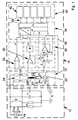
- an unearthed direct or alternating current network in the present case has two mains conductors 12, which are supplied with direct or alternating voltage (U DC , U AC ) by a mains voltage source 14.
- An unavoidable insulation resistance with ohmic and capacitive parts Re, Ce represents a certain network derivation between the network conductors 12 and earth E even when the network conditions are correct.
- the size of the ohmic part Re of this insulation resistance must be monitored. This is done by means of a pulse overlay.
- a monitoring device 16 is connected to the network conductors 12 and earth E via an ohmic network connection 24.
- FIG. 1 shows a measuring pulse with a pulse voltage value Up - pulse alternating voltage source 20 - via an ohmic network connection 24 between the network conductors 12 of the network 10 and earth E, a measuring current flows through the insulation resistance, which is proportional to the ohmic part Re after the transient process is inevitable insulation resistance (parallel connection of Re, Ce) between the network and earth and that of the internal resistance Ri of the measuring device (this includes the ohmic resistance of the Network connection).
- a voltage drop Um from which the ohmic part Re of the insulation resistance between the network 12 to be monitored and earth E can be calculated as follows:
- the transient process is based on the fact that when the measuring pulse is switched on, the capacitive part Ce of the insulation resistance first reaches the voltage value Up * Re / (Ri + Re) must be charged before the measuring current or the voltage drop derived therefrom (measuring current measured value) at Rm can be evaluated as a measure of the ohmic part of the insulation resistance.
- leakage direct currents superimpose the measurement result, namely the measured current measured value. Therefore, in the known pulse superimposition, two measuring pulses with different pulse voltage values are successively superimposed on the network and the associated measured current measured values are recorded. The difference between these measured current measured values eliminates the influence of the leakage direct currents.
- the value Um relevant for the determination of Re can be calculated from the two voltage drops Um1, Um2 at Rm as follows:
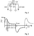
- the two voltages are subtracted in a known manner via a so-called sample & hold circuit according to FIG. 2.
- the first voltage Um1 is applied with the switch S2 closed, and the capacitors C1 and C2 charge up Voltage Um1 on.
- the switch S2 is opened and the second voltage Um2 is applied.
- the capacitor C1 is charged to the second voltage Um2, while the capacitor C2 maintains its previous voltage Um1.
- the differential voltage Um1-Um2 At the output of the sample and hold circuit - or at the input of a downstream measuring amplifier (see Fig. 1) - there is now the differential voltage Um1-Um2 to be evaluated.
- Ri represents the resistance of the parallel connection of Re and Ri. Since the measured variable Re can be infinitely large, tmess is 6 * Ri * Ce as the minimum duration to be set for the individual measuring pulses. For a full measuring cycle (difference formation of the measuring current measured values with two successive measuring pulses), at least twice the minimum duration applies.
- Adaptive measuring pulses are used, so to speak, the length of time of which is continuously adapted to the prevailing network conditions, namely the sizes of Ce and Re. In this way, optimally short measuring times can be achieved.
- FIG. 7 shows the clear temporal advantage of the method according to the invention over the prior art. While there is a constant measuring time tmess of 100% (set to Ce) according to the prior art, the measuring time according to the invention is reduced with decreasing Re to less than 10%. For usual sizes of Re, the measuring time tmeas is reduced to about 50% to 10%.
- FIGS. 3 and 4 for the case without interference frequencies (FIG. 3) and with interference frequencies (FIG. 4), it is shown how the transient processes of the voltage at Rm are monitored.
- the voltage rises steeply when Ce is charged (limited by the internal resistance Ri and slightly throttled by the choke 26), and then after an e-function to the final value Um1 or Um2 to be measured (measured current value in steady state) or to increase with a negative pulse voltage value.
- the measurement samples are detected by the fact that in certain mean measurement intervals between t0 and t1; t1 and t2 etc. arithmetic averaging of the voltage at Rm. In this way, interference frequencies can be eliminated by measurement. If the difference between two successive measurement samples Ua i and Ub i is sufficiently small or no longer measurable, the transient process is deemed to have ended and the measurement current measurement value Um1 or Um2 is recorded.
- the distances between the measuring times and the lengths of the mean value measuring intervals increase over time from a starting value t n0 or t n0 disturb .
- the starting value should be as small as possible so that short transient processes (Re and / or Ce small) can be detected as quickly as possible.
- the start value must be sufficiently large that long settling processes (Re and / or Ce large) are not immediately treated as finished because of the small differences in the test samples and the limited measurement resolution.
- a the still measurable minimum percentage change in measured value
- Cemax is the maximum expected system leakage capacitance (capacitive part Ce of the insulation resistance; Ce is, for example, about 150 ⁇ F).
- This start value must be increased to t nOstör if due to an existing interference frequency f stör of the value of t nOstör proves greater than t n0.
- a certain initial value of the interference frequency of, for example, 25 Hz is assumed - if the actual interference frequency should be different, in particular smaller, an automatic adjustment takes place in the course of the measuring method.
- the value of the ohmic insulation resistance calculated after the difference is only used as the correct end value when the end values determined in two successive measuring cycles or the difference values match. In this way, incorrect measurements can be avoided, which are based, for example, on the fact that the power supply ratio has changed in the meantime or that the actual interference frequency f interference deviates from the assumed initial value of 25 Hz by erroneous values.
- the starting value t n0stör (measuring interval for averaging the test sample) for the next measuring cycle each enlarged, as doubled by halving f disturb . This change continues until two identical end values are determined or until a minimum value of the interference frequency of, for example, 0.1 Hz has been reached. This automatically adjusts the measuring intervals to the actual interference frequency.
- the measuring time is extended in accordance with the interference frequency.
- the approximate size of the interference frequency is determined by measuring the time between maximum and minimum values at the end of a measuring cycle. If an actual interference frequency is greater than interference, then interference is adjusted accordingly and the mean value measurement interval or measurement time is shortened accordingly.
- a circuit part 18 of the measuring device 16 contains the above-mentioned parts 20, 22 and 24, which are connected in series between earth E and the line conductors 12. Between the network connection 24, which has four ohmic resistors in the present case, and the measuring resistor 22 or Rm a low-pass filter with a choke 26 and a capacitor 27 connected to earth E.
- the low-pass filter ensures that the higher-frequency interference components, as well as the mains frequency, are filtered out of the measuring branch.
- the voltage across the measuring resistor Rm or 22 is fed to a subtraction circuit 28 with an input-side resistor R and a subtraction element connected to it in the form of a sample and hold circuit which has two capacitors C1, C2 and a switch S2 bridging the capacitor C2 in the closed state.
- the subtractor which corresponds to the detail from FIG. 2 and operates accordingly, is connected on the output side to a measuring amplifier, not designated, from which the Measured value difference Um1-Um2 corresponding output signal U1 reaches an analog / digital converter A / D of a programmable microcontroller 34.
- the switch S2 controlled by the microcontroller 34 is initially closed until, after settling in, Um1 is stored in C2. Then S2 is opened and Um2 is stored in C1 after the transient has settled.
- a switch S1 bridging the capacitor C2 in the closed state, also controlled by the microcontroller 34, serves only the purpose of switching off the function of the subtractor in the event that a difference formation is not required, for example when none in an AC network due to missing converters or the like disturbing leakage direct currents occur in the network 12. Then circuit 28 can direct the voltage at Rm directly to microcontroller 34.
- the voltage across the measuring resistor Rm or 22 is also fed to an active rectifier circuit 30 with a measuring amplifier (not designated) and a rectifier element connected to it.
- Its output signal U2 which is also fed to the analog / digital converter A / D of the microcontroller 34, represents the rectified settling processes of the voltage at Rm. It is thus possible in principle with this signal U2 and the microcontroller 34 to monitor all positive and negative settling processes and the Determine transient conditions.
- the signal U2 falsified by leakage direct currents is only used to treat the negative transient processes, while the positive transient processes are tracked on the smaller difference signal U1 not falsified by leakage direct currents.
- the microcontroller 34 determines a transient state through the measurement sample comparisons, it passes a control signal S via a control line 36 to the pulse alternating voltage source 20, which in the present case is designed as a reversible voltage source. Depending on the control signal S, this alternately generates a positive and a negative DC voltage value (positive and negative pulse voltage values of the pulse AC voltage of the same size): the respective pulse voltage value is always retained until a further control signal S arrives.
- the pulse length of the measuring pulses is always adapted by the microcontroller 34 to the actual network conditions, which leads to an optimal shortening of the measuring times.
- the microcontroller 34 determines by evaluating U1 that two successive difference values or end values to be calculated from them for the ohmic insulation resistance Re are essentially the same, the last value of U1 for Re is evaluated and the value of Re is via a line connection 38 fed to an interface 40 with individual links 42.
- the individual elements can contain, for example, a trigger relay for an error, control buttons, a serial interface and the like.
- the mains voltage on the mains conductors 12 is detected via a differential amplifier 32 connected on the input side to the network coupling 24 and on the output side to the analog / digital converter A / D.
- This allows the microcontroller 34 to determine whether the measuring device is actually connected to the network to be monitored.
- the microcontroller 34 can thereby determine via the curve shape whether the measuring device is connected to a direct current network (with a two-pole network connection) or to an alternating current network (with a three-pole network connection).
- an automatic resistance correction can then be carried out. Instead, it is too possible to manually enter the type of network connection to the microcontroller 34 via the interface 40.
- a test switch Sp can disconnect the measuring resistor Rm or 22 from the choke 26 and instead connect the measuring resistor to an ohmic test resistor Rp connected to a control earth KE. This is designed so that it simulates a full earth fault of the network 10 to be monitored.
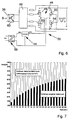
- FIG. 6 A practical exemplary embodiment of the pulse voltage source 20 designed as a reversible voltage source is shown in FIG. 6.
- a bridge circuit 46 consisting of four MOS field-effect transistors 48, 50, 52, 54 supplies via its bridge end points an output DC voltage which, depending on whether the diagonal transistors 48, 54 or 50, 52 are switched on, is either + 27V or -27V.
- the output DC voltage that can be switched between these values represents the pulse voltage values of the pulse AC voltage.
- the bridge center points are connected to the output of a DC voltage source 44. In the present case, this generates a DC voltage of 30V from a small DC input voltage of 12V via a galvanically isolating DC / DC converter 56, from which the stabilized DC voltage of 27V is generated.
- control electrodes of the field effect transistors are connected to the output of a control logic 58, which ensures the mutual switching and blocking of the diagonal field effect transistors.
- the control signal S coming from the microcontroller 34 via the control line 36, which is the control logic, serves as the input signal of the control logic 58 is fed via a galvanically isolating optocoupler 60.
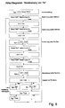
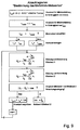
- FIGS. 8 and 9 represent essential steps in the overall sequence of the measuring method.
- a basic setting with default values for f disturb and Cemax is selected first. Then the flow chart of Fig. 9 is called for each of two successive measuring pulses in order to check the transient condition from two measurement samples obtained by averaging and for the two Measuring pulses determine the last measuring current measured value Um1 (first pulse), Um2 (second pulse) which is decisive in the transient state. A first insulation value Re1 for Re is then calculated from this. The whole process is then repeated to determine a second insulation value Re2 for Re. If the amount of Re1 and Re2 are completely or almost identical, it is assumed that the result is correct and the mean value of Re1, Re2 is calculated as a measure for Re.
- the starting value t n0 of the measuring intervals for generating the mean value of the measuring samples is first determined. Then two successive samples are compared. This process is repeated, increasing the measuring intervals, until two measuring samples match and the last measuring sample is adopted as the measuring current measured value Um.
Landscapes
- Physics & Mathematics (AREA)
- General Physics & Mathematics (AREA)
- Measurement Of Resistance Or Impedance (AREA)
- Arrangements For Transmission Of Measured Signals (AREA)
- Interface Circuits In Exchanges (AREA)
- Monitoring And Testing Of Transmission In General (AREA)
- Investigating Or Analyzing Materials By The Use Of Electric Means (AREA)
- Air Bags (AREA)
- Measurement Of Current Or Voltage (AREA)
- Testing Of Short-Circuits, Discontinuities, Leakage, Or Incorrect Line Connections (AREA)
Abstract
Description
Die Erfindung betrifft ein Verfahren zur Isolationsüberwachung von ungeerdeten Gleich- und Wechselstromnetzen gemäß dem Oberbegriff von Anspruch 1 und eine zum Durchführen dieses Verfahrens geeignete Einrichtung gemäß dem Oberbegriff von Anspruch 21.The invention relates to a method for monitoring the insulation of unearthed direct and alternating current networks according to the preamble of
Demnach befaßt sich die Erfindung mit der Isolationsüberwachung von ungeerdeten Gleichstromnetzen und Wechselstromnetzen im Betrieb und insbesondere auch von solchen Wechselstromnetzen, in denen durch angeschlossene Gleich-, Wechsel- oder sonstige Stromrichter Ableitgleichströme sowie nieder- und hochfrequente Anteile auftreten, die über den unvermeidbaren ohmschen Teil des Isolationswiderstands zwischen Netz und Erde fließen.Accordingly, the invention is concerned with the insulation monitoring of unearthed direct current networks and alternating current networks in operation and in particular also of those alternating current networks in which leakage direct currents and low and high-frequency components occur due to connected direct current, alternating current or other power converters which occur via the unavoidable ohmic part of the Insulation resistance between the mains and earth flow.
In reinen Wechselstromnetzen kann der ohmsche Teil des Isolationswiderstands des Netzes im Betrieb dadurch gemessen werden, daß dem Netz über eine ohmsche Netzankopplung zwischen Netz und Erde eine konstante Meßgleichspannung überlagert wird. Der aufgrund dieser Meßgleichspannung über die Netzankopplung, das Netz und den ohmschen Isolationswiderstand fließende Meßgleichstrom ist hinsichtlich seiner Größe proportional zur Größe des ohmschen Isolationswiderstandes, so daß dieser Widerstand aus dem Meßgleichstrom bzw. einem hieraus abgeleiten Meßstrom-Meßwert, wie einer Spannung, bestimmt werden kann. Dabei können störende Frequenzeinflüsse durch einen Tiefpaß ausgefiltert werden.In pure AC networks, the ohmic part of the insulation resistance of the network can be measured during operation by superimposing a constant DC measurement voltage on the network via an ohmic network connection between the network and earth. The due this DC measuring voltage via the network coupling, the network and the ohmic insulation resistance, the measurement DC current flowing is proportional in size to the size of the ohmic insulation resistance, so that this resistance can be determined from the DC measurement current or a measurement current measurement value derived therefrom, such as a voltage. Interfering frequency influences can be filtered out by a low-pass filter.
In Gleichstromnetzen und in Wechselstromnetzen, in denen die erwähnten Ableitgleichströme auftreten können, addiert (oder subtrahiert) sich zum Meßgleichstrom eine auf einem Ableitgleichstrom beruhende Gleichstrom-Störkomponente, die bei Verwendung einer Meßgleichspannung zu Fehlmessungen führt. Zur Eliminierung dieser Störkomponente kann dem Netz statt einer Meßgleichspannung eine Impulswechselspannung mit unterschiedlichen Impulsspannungswerten überlagert werden. Um zusätzlich auch den kapazitven Einfluß des Isolationswiderstandes zu eliminieren, wird der jeweilige Meßstrom-Meßwert stets erst nach dem Einschwingen des Netzes auf den jeweiligen Impulsspannungswert erfaßt. Aus der Differenz zweier aufeinanderfolgender Meßstrom-Meßwerte wird dann der ohmsche Isolationswiderstand bestimmt. Durch die Differenzbildung entfällt der Einfluß der Störkomponente.In direct current networks and in alternating current networks in which the mentioned leakage direct currents can occur, a direct current interference component based on a leakage direct current is added (or subtracted) to the measurement direct current, which leads to incorrect measurements when using a measurement direct voltage. To eliminate this interference component, an alternating pulse voltage with different pulse voltage values can be superimposed on the network instead of a DC measurement voltage. In order to additionally eliminate the capacitive influence of the insulation resistance, the respective measured current measured value is always only recorded after the network has settled to the respective pulse voltage value. The ohmic insulation resistance is then determined from the difference between two successive measured current measured values. The influence of the interference component is eliminated by forming the difference.
Solche Verfahren mit Impulsüberlagerung sind beispielsweise in DE 33 46 387 C2, DE 25 09 661 C2 und in der deutschen Offenlegungsschrift 26 18 303 beschrieben. Sie haben jedoch den Nachteil, daß der Meßtakt eines dabei benutzten Impulsgenerators für die Erzeugung der Impulswechselspannung stets fest auf den maximal zu erwartenden kapazitiven Isolationswiderstand (Ableitkapazität) zwischen Netz und Erde abgestimmt werden muß (das heißt, daß die maximal zu erwartende Zeitkonstante zum Einschwingen der Meßspannung auf das Netz berücksichtigt werden muß). Dieses führt zu teils extrem langen Meßzeiten. Wenn zur Verkürzung der Meßzeit ein kürzerer Meßtakt, also eine größere Impulsfolgefrequenz, gewählt wird, können sich erhebliche Meßwertverfälschungen ergeben.Such methods with impulse superposition are described, for example, in DE 33 46 387 C2, DE 25 09 661 C2 and in
Der vorliegenden Erfindung liegt daher die Aufgabe zugrunde, ein Verfahren zur Isolationsüberwachung von ungeerdeten Gleich- und Wechselstromnetzen gemäß dem Oberbegriff von Anspruch 1 und eine zum Durchführen dieses Verfahrens geeignete Einrichtung gemäß dem Oberbegriff von Anspruch 21 so zu gestalten, daß sich bei einfacher Handhabung und mit einfachen Maßnahmen bei beliebigen ungeerdeten Netzen unter Vermeidung von Meßwertverfälschungen kürzere Meßzeiten erzielen lassen.The present invention is therefore based on the object of designing a method for monitoring the insulation of ungrounded direct and alternating current networks according to the preamble of
Zur Lösung der gestellten Aufgabe zeichnet sich ein Verfahren zur Isolationsüberwachung von ungeerdeten Gleich- und Wechselstromnetzen der im Oberbegriff von Anspruch 1 genannten Art erfindungsgemäß durch die im Kennzeichen dieses Anspruchs aufgeführten Merkmale aus.To achieve the object, a method for monitoring the insulation of unearthed direct and alternating current networks of the type mentioned in the preamble of
Erfindungsgemäß werden somit die Einzelimpulse der Impulswechselspannung hinsichtlich ihrer Länge an das jeweils vorhandene Netz stets so angepaßt, daß unverzüglich dann auf den nächsten Impulsspannungswert umgeschaltet wird, wenn der laufend überwachte Einschwingvorgang beendet ist. Dadurch erfolgt eine ständige Anpassung des Meßverfahrens an die momentanen Netzverhältnisse, so daß sich optimal kurze Meßzeiten erzielen lassen, ohne daß irgendeine Gefahr von Fehlmessungen besteht. Auf diese Weise entfällt die Notwendigkeit der Verwendung einer Impulswechselspannung mit auf die ungünstigsten Netzverhältnisse anzupassender und dadurch notwendigerweise relativ kleiner sowie konstanter Impulsfolgefrequenz. Das Meßergebnis des ohmschen Isolationswiderstandes kann nach dem neuen Verfahren bereits nach einer Meßzeit erzielt werden, die je nach Größe der ohmschen und kapazitiven Teile des Isolationswiderstandes im Optimalfall nur etwa 10% der Meßzeit bei herkömmlichen Verfahren entspricht. Dieser Wert steigt zwar mit größer werdendem ohmschen Isolationswiderstand an, doch ist auch bei ungünstigeren Verhältnissen eine deutliche Zeitersparnis von beispielsweise etwa 50% erzielbar. Die Verwendung einer Impulsüberlagerung mit einem "adaptiven Meßimpuls" im Sinne dieser Erfindung führt auch zu einer einfacheren Handhabung des Meßverfahrens, weil sich das Verfahren hinsichtlich der jeweiligen Impulslangen stets selbsttätig anpassen kann.According to the invention, the individual pulses of the pulse alternating voltage are thus always adapted in terms of their length to the respective existing network so that the next pulse voltage value is immediately switched over when the continuously monitored transient process has ended. This results in a constant adaptation of the measuring method to the current network conditions, so that optimally short measuring times can be achieved without any risk of incorrect measurements. In this way, there is no need to use an alternating pulse voltage with a pulse repetition frequency that is to be adapted to the most unfavorable network conditions and therefore necessarily relatively small and constant. The measurement result of the ohmic insulation resistance can be achieved using the new method after a measurement time which, depending on the size of the ohmic and capacitive parts of the insulation resistance, is only about 10% in the optimal case. corresponds to the measuring time in conventional methods. Although this value increases with increasing ohmic insulation resistance, significant time savings of, for example, about 50% can be achieved even under less favorable conditions. The use of a pulse superimposition with an "adaptive measuring pulse" in the sense of this invention also leads to a simpler handling of the measuring method, because the method can always adapt automatically with regard to the respective pulse lengths.
Die weiteren Ausgestaltungen gemäß den Ansprüchen 2 und 3 sehen zur Überwachung der Einschwingvorgänge auf die verschiedenen Impulsspannungswerte einzelne Meßproben zu bestimmten Meßzeitpunkten oder aber zur meßtechnischen Eliminierung von Störfrequenzen solche Meßproben vor, die durch Mittelwertbildung in bestimmten Meßintervallen erhalten werden. Da in vielen Netzen solche Störfrequenzen auftreten, hat sich die Mittelwertbildung in praktischen Versuchen besonders bewährt.The further refinements according to
Gemäß den Weiterbildungen der Ansprüche 4 und 5 sollten die Zeitabstände der Meßzeitpunkte bzw. die Längen der Mittelwert-Meßintervalle bei der Überwachung eines jeden Einschwingvorgangs mit der Zeit größer werden. Hierdurch soll verhindert werden, daß der Überwachungsvorgang vorzeitig dadurch abgebrochen wird, weil zu kleine, nicht mehr ohne weiteres meßbare Unterschiede der Meßproben auftreten. Durch das Vergrößern der Zeitabstände bzw. Meßintervalle wird erreicht, daß sich während des Einschwingvorgangs stets ausreichend große Meßproben-Unterschiede ergeben und somit das Ende des Einschwingvorgangs sicher erfaßbar ist. Zur Reduzierung der Meßzeit sollte anfangs ein möglichst kleiner Startwert gewählt werden, der bei den ungünstigsten Netzverhältnissen, also bei großer Zeitkonstante, gerade noch ein sicheres meßtechnisches Feststellen des Einschwingvorgangs ermöglicht.According to the developments of claims 4 and 5, the time intervals of the measuring times or the lengths of the mean value measuring intervals should become larger over time when monitoring each transient process. This is to prevent the monitoring process from being terminated prematurely because differences in the measurement samples which are too small and no longer readily measurable occur. By increasing the time intervals or measuring intervals it is achieved that there are always sufficiently large measurement sample differences during the transient process and thus the end of the transient process can be reliably detected. In order to reduce the measuring time, a starting value that is as small as possible should initially be selected, which, in the most unfavorable grid conditions, that is to say with a large time constant, just enables the measuring process to be reliably determined.
Die Startwerte des Meßproben - Zeitabstands bzw. des Mittelwert - Meßintervalls lassen sich unter Berücksichtigung der jeweiligen Netzverhältnisse bevorzugt nach den Vorschriften der Ansprüche 6 bis 8 wählen.The starting values of the measurement sample time interval or the mean value measurement interval can be selected in accordance with the regulations of claims 6 to 8, taking into account the respective network conditions.
Die während der Überwachung eines jeden Einschwingvorgangs erfolgende Vergrößerung der Meßproben - Zeitabstände bzw. der Mittelwert-Meßintervalle sollte zur Vereinfachung des Verfahrens und zur Erzielung einwandfreier Meßergebnisse bevorzugt nach den Vorschriften der Ansprüche 9 bist 11 erfolgen. Nach den Ansprüchen 10 und 11 kann erreicht werden, daß der Überwachungsvorgang bei einer maximalen meßtechnischen Auflösung von etwa 1% nicht vor Erreichen der ca. 6-fachen Zeitkonstante des Einschwingvorgangs endet, also nicht zu früh abgebrochen wird.The enlargement of the measurement samples - time intervals or the average measurement intervals, which takes place during the monitoring of each transient process, should preferably be carried out in accordance with the regulations of claims 9 to 11 in order to simplify the method and to achieve perfect measurement results. According to
Die Weiterbildung von Anspruch 12 erhöht die Meßsicherheit und schaltet Fehlmessungen aus, beispielsweise solche aufgrund sich ändernder Netzverhältnisse.The development of
Mit den bevorzugten Weiterbildungen der Ansprüche 13 bis 16 lassen sich sehr günstige Verhältnisse für die Mittelwertbildung erzielen, indem die anfänglich angenommene Störfrequenz zur Bestimmung des jeweiligen Startwerts des Mittelwert-Meßintervalls dann, wenn sich kein eindeutiges Meßergebnis erzielen läßt, innerhalb einer bestimmten Grenze solange verkleinert wird, bis ein sicheres Meßergebnis vorliegt. Für den nächsten Meßzyklus kann die tatsächliche Größe einer vorhandenen größeren Störfrequenz gemessen und dann sofort bei der Festlegung des Startwerts berücksichtigt werden.With the preferred developments of claims 13 to 16, very favorable conditions for averaging can be achieved by reducing the initially assumed interference frequency for determining the respective starting value of the mean value measuring interval within a certain limit when no clear measuring result can be achieved until a reliable measurement result is available. For the next measurement cycle, the actual size of an existing, larger interference frequency can be measured and then immediately taken into account when determining the start value.
Gemäß den Ansprüchen 17 bis 20 können sehr verschiedene Arten von Impulswechselspannungen eingesetzt werden. Wichtig ist dabei lediglich, daß die Einschwingvorgänge auf verschiedene Impulsspannungswerte erfolgen, beobachtet und durch Differenzbildung ausgewertet werden, wodurch die störenden Ableitgleichströme meßtechnisch eliminiert werden.According to claims 17 to 20, very different types of alternating pulse voltages can be used. It is only important that the transient processes take place at different pulse voltage values, observed and by difference formation are evaluated, whereby the disturbing leakage direct currents are eliminated by measurement.
Zur Lösung der gestellten Aufgabe zeichnet sich ferner eine zum Durchführen des obigen Verfahrens geeignete Einrichtung der im Oberbegriff von Anspruch 21 genannten Art erfindungsgemäß durch die im Kennzeichen dieses Anspruchs aufgeführten Merkmale aus.To achieve the object, a device suitable for carrying out the above method of the type mentioned in the preamble of claim 21 is furthermore distinguished according to the invention by the features listed in the characterizing part of this claim.
Die Impulswechselspannungsquelle ist demnach nicht wie beim Stand der Technik als ein Impulsgenerator mit fester Impulsfolgefrequenz ausgebildet, sondern als eine durch ein Steuersignal umsteuerbare Spannungsquelle mit verschiedenen Gleich- bzw. Impulsspannungswerten. Das Umsteuern der Spannungsquelle auf die verschiedenen Gleichspannungswerte erfolgt jeweils beim Erreichen des von der Auswerteeinheit überwachten Einschwingzustandes. Eine solche Einrichtung ist besonders einfach zu handhaben und paßt sich selbst den jeweiligen Netzverhältnissen optimal an, und zwar auch dann, wenn sich die Netzverhältnisse im Laufe der Zeit ändern.The pulse alternating voltage source is therefore not designed as a pulse generator with a fixed pulse repetition frequency, as in the prior art, but rather as a voltage source with different direct or pulse voltage values that can be reversed by a control signal. The reversal of the voltage source to the various DC voltage values takes place each time the transient state monitored by the evaluation unit is reached. Such a device is particularly easy to use and adapts itself optimally to the respective network conditions, even if the network conditions change over time.
Gemäß der Weiterbildung von Anspruch 22 ist es mit einem integrierten programmierbaren Mikrokontroller möglich, eine möglichst "intelligente" und flexible Auswerteinheit mit einer geringen Anzahl von Bauteilen zu erstellen. Der Mikrokontroller enthält nahezu alle erforderlichen Schaltungsteile (AD-Wandler, Datenspeicher, Timer, Eingangs/Ausgangsschaltungen, Programmspeicher etc) in einem Gehäuse. Nach der Analog/Digital-Wandlung der Meßproben, Meßstrom-Meßwerte und Meßwertdifferenzen können alle erforderlichen Auswertungen und Aktivitäten über ein in dem Programmspeicher des Mikrokontrollers befindliches Ablaufprogramm gesteuert werden. Parameter und Einstellungen können auf einem Display angezeigt, über ein Interface (Tastatur, serielle Schnittstelle) eingegeben bzw. verändert und in einem elektrisch löschbaren Festwertspeicher (EEPROM) gespeichert werden.According to the development of
Die Ausgestaltungen der Ansprüche 23 und 24 ermöglichen es, daß der Mikrokontroller die Einschwingvorgänge genau überwachen und den ohmschen Teil des Isolationswiderstandes aus der Differenzbildung der Subtrahierschaltung bestimmen kann. Das Einschwingen könnte grundsätzlich immer am Ausgangssignal des aktiven Gleichrichters überwacht werden. Gemäß Anspruch 25 wird jedoch das Einschwingen auf den positiven Gleichspannungswert am Ausgang der Subtrahierschaltung überwacht, weil dieses nicht durch Ableitgleichströme beeinflußte kleinere Differenzsignal eine genauere Überwachung über die Analog/Digital-Wandlung ermöglicht.The refinements of
Eine Gleichspannungsquelle gemäß den Ansprüchen 26 bis 28 arbeitet zuverlässig und ist besonders leicht sowie preiswert herstellbar. Ein DC/DC-Wandler ermöglicht das Erzeugen einer relativ großen Brückenversorgungsgleichspannung aus einer relativ kleinen Eingangsgleichspannung. Es ist besonders bevorzugt, versorgungsseitig und steuersignalseitig galvanische Trennungen gemäß den Ansprüchen 29 bis 31 vorzusehen.A DC voltage source according to
Die Maßnahmen der Ansprüche 32 bis 35 ermöglichen eine wirksame Überwachung auf einen korrekten Anschluß der Einrichtung an das Netz sowie an Erde und auf eine korrekte Arbeitsweise der Auswerteeinheit. Hierdurch können Fehlanschlüsse und Meßfehler sicher vermieden werden.The measures of
Gemäß Anspruch 36 kann dieselbe Einrichtung zweipolig an ein Gleichstromnetz oder dreipolig an ein Wechselstromnetz angekoppelt werden. Die hiervon abhängige Innenwiderstandsänderung kann über die Ankoppelart eingegeben oder über die Netzspannungsform (AC oder DC) selbsttätig erfaßt sowie berücksichtigt werden.According to
Ein gemäß den Ansprüchen 37 und 38 bevorzugter Tiefpaß sorgt dafür, daß höherfrequente Störfrequenzen, wie auch die Netzfrequenz, von dem Meßstrompfad ferngehalten werden können. Die den Tiefpaß durchlaufenden niederfrequenten Störfrequenzsignale können durch die erwähnte Mittelwertbildung meßtechnisch eliminiert werden.A low-pass filter preferred according to
Die Erfindung wird nachfolgend unter anderem an zeichnerisch dargestellten Ausführungsbeispielen näher erläutert. Es zeigen:
- Fig. 1 eine Einrichtung nach der vorliegenden Erfindung in einer prinzipiellen Übersichtsdarstellung,
- Fig. 2 eine für eine Differenzbildung sorgende Subtrahierschaltung als Einzelteil der Einrichtung aus Fig 1,
- Fig. 3 Einschwingvorgänge auf positive und negative Impulsspannungswerte mit einer Entnahme von Meßproben zu bestimmten Meßzeitpunkten,
- Fig. 4 einen sich auf einen positiven Impulsspannungswert beziehenden Teil der Einschwingvorgänge mit einer Entnahme von Meßproben, die zur Eliminierung von Störfrequenzen durch Mittelwertbildung in bestimmten Meßintervallen gewonnen werden,
- Fig. 5 eine Prüfschaltung zum Überwachen eines korrekten Erdanschlusses und einer korrekten Arbeitsweise einer Auswerteeinheit der Einrichtung,
- Fig. 6 eine steuerbare Schaltung zum Erzeugen einer großen Ausgangsspannung mit gleich großen positiven und negativen Impulsspannungswerten aus einer kleinen Eingangsgleichspannung,
- Fig. 7 in einer Vergleichsdarstellung den deutlichen zeitlichen Vorteil des erfindungsgemäßen Verfahrens mit einem "adaptiven" (längenmäßig angepaßten) Meßimpuls gegenüber dem bekannten Verfahren mit einem "statischen" (langenmäßig konstanten) Meßimpuls,
- Fig. 8 ein erstes Ablaufdiagramm zum Bestimmen des ohmschen Teils des Isolationswiderstandes und
- Fig. 9 ein vom ersten Ablaufdiagramm aufgerufenes zweites Ablaufdiagramm zum Bestimmen von Meßstrom-Meßwerten.
- 1 shows a device according to the present invention in a basic overview,
- FIG. 2 shows a subtracting circuit that provides a difference as an individual part of the device from FIG. 1, FIG.
- 3 settling processes to positive and negative pulse voltage values with taking measurement samples at certain measuring times,
- 4 shows a part of the transient processes relating to a positive pulse voltage value with a removal of measurement samples which are obtained in order to eliminate interference frequencies by averaging at certain measurement intervals,
- 5 shows a test circuit for monitoring a correct earth connection and a correct functioning of an evaluation unit of the device,
- 6 shows a controllable circuit for generating a large output voltage with equally large positive and negative pulse voltage values from a small DC input voltage,
- Fig. 7 in a comparison, the clear temporal advantage of the method according to the invention with an "adaptive" (length-adjusted) measuring pulse compared to the known method with a "static" (constant in length) measuring pulse,
- 8 shows a first flow chart for determining the ohmic part of the insulation resistance and
- 9 shows a second flowchart called by the first flowchart for determining measured current measured values.
Zunächst wird auf das bekannte Verfahren mit einer Impulsüberlagerung von Meßimpulsen konstanter Impulsfolgefrequenz näher eingegangen.First, the known method with a pulse superimposition of measuring pulses of constant pulse repetition frequency is discussed in more detail.
In Fig. 1 weist ein allgemein mit 10 bezeichnetes ungeerdetes Gleich- oder Wechselstromnetz im vorliegenden Fall zwei Netzleiter 12 auf, die von einer Netzspannungsquelle 14 mit Gleich- oder Wechselspannung (UDC, UAC) beaufschlagt sind. Ein unvermeidbarer Isolationswiderstand mit ohmschen und kapazitiven Teilen Re, Ce stellt auch bei korrekten Netzverhältnissen eine gewisse Netzableitung zwischen den Netzleitern 12 und Erde E dar. Die Größe des ohmschen Teils Re dieses Isolationswiderstands muß überwacht werden. Das erfolgt mittels einer Impulsüberlagerung. Zu diesem Zweck wird eine Überwachungseinrichtung 16 über eine ohmsche Netzankopplung 24 mit den Netzleitern 12 und Erde E verbunden.In FIG. 1, an unearthed direct or alternating current network, generally designated 10, in the present case has two
Legt man gemäß Fig. 1 einen Meßimpuls mit einem Impulsspannungswert Up - Impulswechselspannnungsquelle 20 - über eine ohmsche Netzankopplung 24 zwischen die Netzleiter 12 des Netzes 10 und Erde E, so fließt über den Isolationswiderstand ein Meßstrom, der nach dem Einschwingvorgang proportional zum ohmschen Teil Re des unvermeidbaren Isolationswiderstands (Parallelschaltung von Re, Ce) zwischen dem Netz sowie Erde ist und der vom Innenwiderstand Ri der Meßeinrichtung (hierzu gehört der ohmsche Widerstand der Netzankopplung) abhängt. An einem Meßwiderstand Rm - Widerstand 22 - kommt es zu einem Spannungsabfall Um, aus dem man den ohmschen Teil Re des Isolationswiderstands zwischen dem zu überwachenden Netz 12 und Erde E wie folgt berechnen kann:
Der Einschwingvorgang beruht darauf, daß beim Einschalten des Meßimpulses zunächst der kapazitive Teil Ce des Isolationswiderstandes auf den Spannungswert ![]()
The transient process is based on the fact that when the measuring pulse is switched on, the capacitive part Ce of the insulation resistance first reaches the voltage value ![]()
Bei in Betrieb befindlichen Gleich- und Wechselstromnetzen überlagern Ableitgleichströme das Meßergebnis, nämlich den Meßstrom-Meßwert. Deshalb werden bei der bekannten Impulsüberlagerung dem Netz nacheinander zwei Meßimpulse mit unterschiedlichen Impulsspannungswerten überlagert und die zugehörigen Meßstrom-Meßwerte erfaßt. Durch Differenzbildung dieser Meßstrom-Meßwerte entfällt der Einfluß der Ableitgleichströme.With direct and alternating current networks in operation, leakage direct currents superimpose the measurement result, namely the measured current measured value. Therefore, in the known pulse superimposition, two measuring pulses with different pulse voltage values are successively superimposed on the network and the associated measured current measured values are recorded. The difference between these measured current measured values eliminates the influence of the leakage direct currents.
Wenn beispielsweise zwei Meßimpulse mit gegenpoligen Impulsspannungswerten benutzt werden, läßt sich aus den beiden Spannungsabfällen Um1, Um2 an Rm der für die Bestimmung von Re maßgebliche Wert Um wie folgt berechnen:
Die Subtraktion der beiden Spannungen erfolgt in bekannter Weise über eine sogenannte Sample&Hold-Schaltung gemäß Fig. 2. Zunächst wird die erste Spannung Um1 bei geschlossenem Schalter S2 angelegt, und die Kondensatoren C1 und C2 laden sich auf die Spannung Um1 auf. Dann werden der Schalter S2 geöffnet und die zweite Spannung Um2 angelegt. Dabei wird der Kondensator C1 auf die zweite Spannung Um2 aufgeladen, während der Kondensator C2 seine vorherige Spannung Um1 beibehält. Am Ausgang der Sample&Hold-Schaltung - bzw. am Eingang eines nachgeschalteten Meßverstärkers (siehe Fig. 1) - ergibt sich nun die auszuwertende Differenzspannung Um1-Um2..If, for example, two measuring pulses with opposite-pole pulse voltage values are used, the value Um relevant for the determination of Re can be calculated from the two voltage drops Um1, Um2 at Rm as follows:
The two voltages are subtracted in a known manner via a so-called sample & hold circuit according to FIG. 2. First, the first voltage Um1 is applied with the switch S2 closed, and the capacitors C1 and C2 charge up Voltage Um1 on. Then the switch S2 is opened and the second voltage Um2 is applied. The capacitor C1 is charged to the second voltage Um2, while the capacitor C2 maintains its previous voltage Um1. At the output of the sample and hold circuit - or at the input of a downstream measuring amplifier (see Fig. 1) - there is now the differential voltage Um1-Um2 to be evaluated.
Der wesentliche Nachteil des bekannten Impulsüberlagerungsverfahrens besteht darin, daß die Impulsdauer der mit einem fest eingestellten Impulsgenerator erzeugten Meßimpulse an die Länge des längstmöglichen Einschwingvorgangs und damit auch an den maximal möglichen kapazitiven Teil Ce des Isolationswiderstandes angepaßt werden muß. Wenn nämlich die Messungen vor dem Erreichen der Einschwingzustände erfolgen, treten deutliche Meßfehler bezüglich Re auf. Die Messungen können jeweils erst nach einer Meßzeit tmess vorgenommen werden, die etwa der 6-fachen Zeitkonstante entspricht und sich aus folgender Formel ergibt:
![]()
Hierbei stellt Re || Ri den Widerstand der Parallelschaltung von Re und Ri dar. Da die Meßgröße Re maximal unendlich groß sein kann, beträgt tmess als einzustellende Mindestdauer für die einzelnen Meßimpulse 6 * Ri * Ce. Für einen vollen Meßzyklus (Differenzbildung der Meßstrom-Meßwerte bei zwei aufeinanderfolgenden Meßimpulsen) gilt demnach wenigstens die doppelte Mindestdauer.The main disadvantage of the known pulse superposition method is that the pulse duration of the measurement pulses generated with a fixed pulse generator must be adapted to the length of the longest possible transient process and thus also to the maximum possible capacitive part Ce of the insulation resistance. If the measurements are made before the transient conditions are reached, clear measurement errors with respect to Re occur. The measurements can only be carried out after a measuring time tmeas, which corresponds approximately to 6 times the time constant and results from the following formula:
![]()
Here Re || Ri represents the resistance of the parallel connection of Re and Ri. Since the measured variable Re can be infinitely large, tmess is 6 * Ri * Ce as the minimum duration to be set for the individual measuring pulses. For a full measuring cycle (difference formation of the measuring current measured values with two successive measuring pulses), at least twice the minimum duration applies.
Es folgt nunmehr die Beschreibung der Besonderheiten der vorliegenden Erfindung.The characteristics of the present invention will now be described.
Im Rahmen der vorliegenden Erfindung werden keine fest eingestellten Meßimpulse mehr verwendet. Stattdessen werden die einzelnen Einschwingvorgänge auf verschiedene Impulsspannungswerte laufend überwacht, und die Meßimpulse werden jeweils sofort nach Erreichen der Einschwingzustände und nach Durchführung der Messungen beendet. Es werden sozusagen "adaptive" Meßimpulse verwendet, deren zeitliche Länge laufend den jeweils vorhandenen Netzverhältnissen, nämlich den Größen von Ce und Re, angepaßt wird. Hierdurch lassen sich optimal kurze Meßzeiten ezielen.In the context of the present invention, fixed measuring pulses are no longer used. Instead, the individual transients are set to different pulse voltage values continuously monitored, and the measuring pulses are stopped immediately after reaching the transient state and after carrying out the measurements. "Adaptive" measuring pulses are used, so to speak, the length of time of which is continuously adapted to the prevailing network conditions, namely the sizes of Ce and Re. In this way, optimally short measuring times can be achieved.
Aus Fig. 7 ist für ein Beispiel (Ce = 50 µF) der deutliche zeitliche Vorteil des erfindungsgemäßen Verfahrens gegenüber dem Stand der Technik dargestellt. Während nach dem Stand der Technik eine (auf Ce eingestellte) konstante Meßzeit tmess von 100% vorliegt, verkleinert sich die Meßzeit nach der Erfindung mit kleiner werdendem Re bis auf unter 10%. Für übliche Größen von Re vermindert sich die Meßzeit tmess auf etwa 50% bis 10%.For an example (Ce = 50 μF), FIG. 7 shows the clear temporal advantage of the method according to the invention over the prior art. While there is a constant measuring time tmess of 100% (set to Ce) according to the prior art, the measuring time according to the invention is reduced with decreasing Re to less than 10%. For usual sizes of Re, the measuring time tmeas is reduced to about 50% to 10%.
In den Figuren 3 und 4 ist für den Fall ohne Störfrequenzen (Fig. 3) und mit Störfrequenzen (Fig. 4) dargestellt, wie die Einschwingvorgänge der Spannung an Rm überwacht werden. Zu Beginn eines jeden Meßimpulses steigt die Spannung beim Aufladen von Ce steil an (begrenzt durch den Innenwiderstand Ri und leicht gedrosselt durch die Drossel 26), um dann nach einer e-Funktion auf den zu messenden Endwert Um1 bzw. Um2 (Meßstrom-Meßwert im eingeschwungenen Zustand) abzufallen bzw. bei negativem Impulsspannungswert anzusteigen.In FIGS. 3 and 4, for the case without interference frequencies (FIG. 3) and with interference frequencies (FIG. 4), it is shown how the transient processes of the voltage at Rm are monitored. At the beginning of each measuring pulse, the voltage rises steeply when Ce is charged (limited by the internal resistance Ri and slightly throttled by the choke 26), and then after an e-function to the final value Um1 or Um2 to be measured (measured current value in steady state) or to increase with a negative pulse voltage value.
Gemäß Fig. 3 werden bei jedem Meßimpuls zu bestimmten Meßzeitpunkten t₀ bis t₆ Meßproben der Spannung an Rm genommen. Wenn der Unterschied zweier aufeinanderfolgender Meßproben Uai und Ubi ausreichend klein oder nicht mehr meßbar ist, gilt der Einschwingvorgang als beendet, und es wird der Meßstrom-Meßwert Um1 bzw. Um2 erfaßt.3, measurement samples of the voltage at Rm are taken at each measurement pulse at specific measurement times t bestimmten to t₆. If the difference between two successive measurement samples Ua i and Ub i is sufficiently small or no longer measurable, the transient process is deemed to have ended and the measurement current measurement value Um1 or Um2 is recorded.
Gemäß Fig. 4 werden die Meßproben daurch erfaßt, daß in bestimmten Mittelwert-Meßintervallen zwischen t₀ und t₁; t₁ und t₂ etc. eine arithmetische Mittelwertbildung der Spannung an Rm erfolgt. Hierdurch lassen sich Störfrequenzen meßtechnisch eliminieren. Wenn der Unterschied zweier aufeinanderfolgender Meßproben Uai und Ubi ausreichend klein oder nicht mehr meßbar ist, gilt der Einschwingvorgang als beendet, und es wird der Meßstrom-Meßwert Um1 bzw. Um2 erfaßt.According to FIG. 4, the measurement samples are detected by the fact that in certain mean measurement intervals between t₀ and t₁; t₁ and t₂ etc. arithmetic averaging of the voltage at Rm. In this way, interference frequencies can be eliminated by measurement. If the difference between two successive measurement samples Ua i and Ub i is sufficiently small or no longer measurable, the transient process is deemed to have ended and the measurement current measurement value Um1 or Um2 is recorded.
Die Abstände der Meßzeitpunkte bzw. die Langen der Mittelwert-Meßintervalle vergrößern sich mit der Zeit von einem Startwert tn0 bzw. tn0stör ausgehend. Der Startwert sollte zwar möglichst klein sein, damit kurze Einschwingvorgänge (Re und/oder Ce klein) möglichst schnell erfaßt werden können. Der Startwert muß aber ausreichend groß sein, damit bei langen Einschwingvorgängen (Re und/oder Ce groß) diese wegen der kleinen Unterschiede der Meßproben und der begrenzten Meßauflösung nicht sofort als beendet behandelt werden.The distances between the measuring times and the lengths of the mean value measuring intervals increase over time from a starting value t n0 or t n0 disturb . The starting value should be as small as possible so that short transient processes (Re and / or Ce small) can be detected as quickly as possible. However, the start value must be sufficiently large that long settling processes (Re and / or Ce large) are not immediately treated as finished because of the small differences in the test samples and the limited measurement resolution.
Wenn bei dem Meßverfahren eine maximale digitale Meßauflösung a (die noch meßbare minimale prozentuale Meßwertänderung) angenommen wird - beispielsweise eine Meßauflösung von 0,01 (wie bei Verwendung einer Analog/Digital-Wandlung mit einem Wert von maximal 800 bit und mit minimal 8 bit Auflösung) - ergibt sich der zu wählende Startwert tn0 aus folgendem Formelzusammenhang:
![]()
![]()
Hierin ist Cemax die maximal zu erwartende Netzableitkapazitat (kapazitiver Teil Ce des Isolationswiderstandes; Ce beträgt beispielsweise etwa 150 µF).If a maximum digital measurement resolution a (the still measurable minimum percentage change in measured value) is assumed in the measurement method - for example a measurement resolution of 0.01 (as when using an analog / digital conversion with a value of maximum 800 bit and with minimum 8 bit resolution ) - the start value to be selected t n0 results from the following formula:
![]()
![]()
In this, Cemax is the maximum expected system leakage capacitance (capacitive part Ce of the insulation resistance; Ce is, for example, about 150 µF).
Dieser Startwert muß dann auf tnOstör vergrößert werden, wenn sich aufgrund einer vorhandenen Störfrequenz fstör der Wert von tnOstör größer erweist als tn0. Der neue größere Startwert ergibt sich aus folgender Formel:
![]()
Dieser Startwert stellt bei niederfrequenten Störsignalen sicher, daß eine ausreichend lange Zeit für die Mittelwertbildung vorliegt und keine durch die Störfrequenz bedingten Fehlmessungen auftreten. Am Anfang wird ein bestimmter Anfangswert der Störfrequenz von beispielsweise 25 Hz angenommen - falls die tatsächliche Störfrequenz anders, insbesondere kleiner, sein sollte, erfolgt im Laufe des Meßverfahrens eine selbsttätige Anpassung.This start value must be increased to t nOstör if due to an existing interference frequency f stör of the value of t nOstör proves greater than t n0. The new larger starting value results from the following formula:
![]()
In the case of low-frequency interference signals, this start value ensures that there is a sufficiently long time for averaging and that there are no incorrect measurements due to the interference frequency. At the beginning, a certain initial value of the interference frequency of, for example, 25 Hz is assumed - if the actual interference frequency should be different, in particular smaller, an automatic adjustment takes place in the course of the measuring method.
Nach Festliegen des Startwertes werden bei der digitalen Überprüfung eines jeden Einschwingvorgangs jeweils zwei aufeinanderfolgende Mittelwert-Meßproben aus den Einzelwerten Uai und Ubi nach folgendem Formelzusammenhang gebildet und verglichen:
Der Einschwingzustand auf den Impulsspannungswert eines Meßimpulses liegt unter Berücksichtigung einer maximalen Meßauflösung a=0,01=8 bit dann vor, wenn folgende Gleichung erfüllt ist:
Nach jeder Kontrolle der Einschwingbedingung muß die Zeit tn (Zeitabstand benachbarter Meßzeitpunkte bzw. die Länge des Mittelwert-Meßintervalls) für die nächste Kontrolle um einen bestimmten Faktor f vergrößert werden, damit die Einschwingbedingung nicht vor Erreichen einer Periodendauer von ca. 6 Zeitkonstanten, also 6*T, den Meßimpuls beendet.After the start value has been determined, two consecutive average measurement samples are formed and compared from the individual values Ua i and Ub i using the following formula in the digital check of each transient process:
The state of transient response to the pulse voltage value of a measuring pulse is then given a maximum measuring resolution a = 0.01 = 8 bit if the following equation is fulfilled:
After each check of the transient condition, the time tn (time interval between adjacent measurement times or the length of the mean measurement interval) for the next check must be increased by a certain factor f, so that the transient condition does not occur before a period of approximately 6 time constants has been reached, i.e. 6 * T, the measuring pulse ended.
Aus der Grundgleichung der e-Funktion kann man ableiten, daß zwischen den Zeitpunkten von 6 Zeitkonstanten und 4,38 Zeitkonstanten eine Wertedifferenz von 1% (8bit=1%) besteht. Dies bedeutet, daß die Zeit tn bei Messung des Endwertes, also bei Feststellung des Einschwingzustandes, ca. 6T-4.38T=1.62T betragen sollte. Daraus läßt sich ein optimierter Faktor f = 1,66 für die Vergrößerung der Zeit tn bis zum Feststellen der Einschwingbedingung ableiten.It can be derived from the basic equation of the e-function that there is a value difference of 1% (8bit = 1%) between the times of 6 time constants and 4.38 time constants. This means that the time tn when measuring the final value, i.e. when determining the transient state, should be approx. 6T-4.38T = 1.62T. An optimized factor f = 1.66 for the increase in the time tn until the transient condition is established can be derived from this.
Grundsätzlich ist es bei diesem Verfahren so, daß der nach der Differenzbildung berechnete Wert des ohmschen Isolationswiderstandes erst dann als richtiger Endwert verwertet wird, wenn die in zwei aufeinanderfolgenden Meßzyklen festgestellten Endwerte oder die Differenzwerte übereinstimmen. Damit lassen sich Fehlmessungen vermeiden, die beispielsweise darauf beruhen, daß sich die Netzverhältnisses zwischenzeitlich verändert haben oder daß die tatsächliche Störfrequenz fstör von dem angenommenen Anfangswert von 25 Hz meßwertverfälschend abweicht.It is basically the case with this method that the value of the ohmic insulation resistance calculated after the difference is only used as the correct end value when the end values determined in two successive measuring cycles or the difference values match. In this way, incorrect measurements can be avoided, which are based, for example, on the fact that the power supply ratio has changed in the meantime or that the actual interference frequency f interference deviates from the assumed initial value of 25 Hz by erroneous values.
Wenn bei einem Meßzyklus keine zwei übereinstimmenden Differenz- oder Endwerte für den ohmschen Isolationswiderstand feststellbar sind (wie beim Auftreten sehr niederfrequenter Störsignale infolge einer dann vorhandenen Fehlanpassung der Meßintervalle an die Störfrequenz), wird der Startwert tn0stör (Meßintervall für die Mittelwertbildung der Meßprobe) für den nächsten Meßzyklus jeweils vergrößert, wie durch Halbierung von fstör verdoppelt. Diese Veränderung wird so oft fortgesetzt, bis zwei gleiche Endwerte festgestellt werden oder bis ein Minimalwert der Störfrequenz von beispielsweise 0,1 Hz erreicht ist. Damit erfolgt eine selbsttätige Anpassung der Meßintervalle an die tatsächliche Störfrequenz.If no two matching difference or end values for the ohmic insulation resistance can be determined in one measuring cycle (as when very low-frequency interference signals occur due to a mismatching of the measuring intervals to the interference frequency), the starting value t n0stör (measuring interval for averaging the test sample) for the next measuring cycle each enlarged, as doubled by halving f disturb . This change continues until two identical end values are determined or until a minimum value of the interference frequency of, for example, 0.1 Hz has been reached. This automatically adjusts the measuring intervals to the actual interference frequency.
Dieses hat aber zur Folge, daß sich die Meßzeit entsprechend der Störfrequenz verlängert. Um die Meßzeit nach einem Meßzyklus schnell wieder einer größeren Störfrequenz anzupassen, wird am Ende eines Meßzyklus durch Zeitmessung zwischen Maximal.- und Minimalwerten die ungefähre Größe der Störfrequenz bestimmt. Ergibt sich eine tatsächliche Störfrequenz größer fstör, so werden fstör entsprechend angepaßt und damit das Mittelwert-Meßintervall bzw. die Meßzeit entsprechend verkürzt.However, this has the consequence that the measuring time is extended in accordance with the interference frequency. In order to quickly adapt the measuring time to a larger interference frequency after a measuring cycle, the approximate size of the interference frequency is determined by measuring the time between maximum and minimum values at the end of a measuring cycle. If an actual interference frequency is greater than interference, then interference is adjusted accordingly and the mean value measurement interval or measurement time is shortened accordingly.
Es folgt jetzt eine Beschreibung verschiedener Schaltungsdetails der Einrichtung nach der vorliegenden Erfindung.Various circuit details of the device according to the present invention will now be described.
Gemäß Fig.1 enthält ein Schaltungsteil 18 der Meßeinrichtung 16 die hintereinander zwischen Erde E und die Netzleiter 12 geschalteten, oben erwähnten Teile 20, 22 und 24. Zwischen der im vorliegenden Fall vier ohmsche Widerstände aufweisenden Netzankopplung 24 und dem Meßwiderstand 22 bzw Rm befindet sich ein Tiefpaß mit einer Drossel 26 und einem mit Erde E verbunden Kondensator 27. Der Tiefpaß sorgt für ein Ausfiltern der höherfrequenten Störanteile, wie auch der Netzfrequenz, aus dem Meßzweig.According to FIG. 1, a circuit part 18 of the measuring
Die Spannung am Meßwiderstand Rm bzw. 22 wird einer Subtrahierschaltung 28 mit einem eingangsseitigen Widerstand R und einem an diesen angeschlossenen Subtrahierglied in Form einer Sample&Hold-Schaltung zugeleitet, die zwei Kondensatoren C1, C2 und einen den Kondensator C2 im geschlossenen Zustand überbrückenden Schalter S2 aufweist. Das Subtrahierglied, das der Einzelheit aus Fig. 2 entspricht und entsprechend arbeitet, ist ausgangsseitig an einen nicht bezeichneten Meßverstärker angeschlossen, von dem aus das der Meßwertdifferenz Um1-Um2 entsprechende Ausgangssignal U1 zu einem Analog/Digital-Wandler A/D eines programmierbaren Mikrokontrollers 34 gelangt. Wie es bereits oben erläutert wurde, ist der vom Mikrokontroller 34 gesteuerte Schalter S2 zunächst geschlossen, bis nach erfolgtem Einschwingen Um1 in C2 gespeichert ist. Danach wird S2 geöffnet, und Um2 wird nach dem Einschwingen in C1 gespeichert.The voltage across the measuring resistor Rm or 22 is fed to a
Ein den Kondensator C2 im Schließzustand überbrückender, ebenfalls vom Mikrokontroller 34 gesteuerter Schalter S1, dient lediglich dem Zweck, die Funktion des Subtrahiergliedes für den Fall auszuschalten, daß eine Differenzbildung nicht erforderlich ist, beispielsweise dann, wenn in einem Wechselstromnetz aufgrund fehlender Stromrichter oder dergleichen keine störenden Ableitgleichströme im Netz 12 auftreten. Dann kann die Schaltung 28 die Spannung an Rm direkt zum Mikrokontroller 34 leiten.A switch S1 bridging the capacitor C2 in the closed state, also controlled by the
Die Spannung am Meßwiderstand Rm bzw. 22 wird außerdem einer aktiven Gleichrichterschaltung 30 mit einem nicht bezeichneten Meßverstärker und einem daran angeschlossenen Gleichrichterglied zugeleitet. Dessen ebenfalls dem Analog/Digital-Wandler A/D des Mikrokontrollers 34 zugeleitete Ausgangssignal U2 stellt die gleichgerichteten Einschwingvorgänge der Spannung an Rm dar. Somit ist es mit diesem Signal U2 und dem Mikrokontrollers 34 grundsätzlich möglich, alle positiven und negativen Einschwingvorgänge zu überwachen und die Einschwingzustände festzustellen. Aus Gründen der Erhöhung der Meßgenauigkeit wird jedoch das durch Ableitgleichströme verfälschte Signal U2 nur zur Behandlung der negativen Einschwingvorgänge benutzt, während die positiven Einschwingvorgänge an dem kleineren nicht durch Ableitgleichströme verfälschten Differenzsignal U1 verfolgt werden.The voltage across the measuring resistor Rm or 22 is also fed to an
Sobald der Mikrokontroller 34 durch die Meßprobenvergleiche einen Einschwingzustand feststellt, leitet er über eine Steuerleitung 36 ein Steuersignal S zu der Impulswechselspannungsquelle 20, die im vorliegenden Fall als eine umsteuerbare Spannungsquelle ausgebildet ist. Diese erzeugt in Abhängigkeit von dem Steuersignal S im vorliegenden Fall abwechselnd einen positiven und einen negativen Gleichspannungswert (gleich große positive und negative Impulsspannungswerte der Impulswechselspannung): Der jeweilige Impulsspannungswert bleibt stets solange erhalten, bis ein weiteres Steuersignal S eintrifft. Dadurch wird die Impulslänge der Meßimpulse durch den Mikrokontroller 34 immer den tatsächlichen Netzverhältnissen angepaßt, was zu einer optimalen Verkürzung der Meßzeiten führt.As soon as the
Sobald der Mikrokontroller 34 durch die Auswertung von U1 feststellt, daß zwei aufeinanderfolgende Differenzwerte oder hieraus zu berechnende Endwerte für den ohmschen Isolationswiderstand Re im wesentlichen gleich groß sind, wird der letzte Wert von U1 für Re ausgewertet, und der Wert von Re wird über eine Leitungsverbindung 38 einem Interface 40 mit Einzelgliedern 42 zugeleitet. Die Einzelglieder können außer einem LCD-Display beispielsweise ein Auslöserelais für einen Fehlerfall, Bedientasten, eine serielle Schnittstelle und dergleichen mehr enthalten.As soon as the
Über einen eingangsseitig an die Netzankopplung 24 und ausgangsseitig an den Analog/Digital-Wandler A/D angeschlossenen Differenzverstärker 32 wird die Netzspannung an den Netzleitern 12 erfaßt. Dadurch kann der Mikrokontroller 34 feststellen, ob die Meßeinrichtung tatsächlich an das zu überwachende Netz angeschlossen ist. Außerdem kann der Mikrokontroller 34 hierdurch über die Kurvenform feststellen, ob die Meßeinrichtung an ein Gleichstromnetz (mit einer zweipoligen Netzankopplung) oder an ein Wechselstromnetz (mit einer dreipoligen Netzankopplung) angeschlossen ist. Je nach Art des Netzes und des damit zusammenhängenden Innenwiderstandes der Netzankopplung kann dann eine selbsttätige Widerstandskorrektur vorgenommen werden. Stattdessen ist es aber auch möglich, die Art der Netzankopplung dem Mikrokontroller 34 über das Interface 40 manuell einzugeben.The mains voltage on the
Mit einer Prüfschaltung gemäß Fig. 5 kann überprüft werden, ob die Meßeinrichtung an Erde E angeschlossen ist und richtig arbeitet. Ein Prüfschalter Sp kann die Verbindung des Meßwiderstands Rm bzw. 22 mit der Drossel 26 aufheben und den Meßwiderstand stattdessen mit einem an eine Kontrollerde KE angeschlossenen ohmschen Prüfwiderstand Rp verbinden. Dieser ist so ausgelegt, daß er einen satten Erdschluß des zu überwachenden Netzes 10 simuliert. Damit muß die Auswerteeinheit der Meßeinrichtung einen ohmschen Isolationswiderstand Re = 0 Ohm anzeigen, wenn ein korrekter Erdanschluß vorliegt und die Auswerteeinheit korrekt arbeitet.5 can be used to check whether the measuring device is connected to earth E and is working properly. A test switch Sp can disconnect the measuring resistor Rm or 22 from the
Ein praktisches Ausführungsbeispiel für die als umsteuerbare Spannungsquelle ausgebildete Impulsspannungsquelle 20 ist in Fig. 6 dargestellt. Eine aus vier MOS-Feldeffektransistoren 48, 50, 52, 54 bestehende Brückenschaltung 46 liefert über ihre Brückenendpunkte eine Ausgangsgleichspannung, die je nachdem, ob die diagonalen Transistoren 48, 54 oder 50, 52 durchgeschaltet sind, entweder +27V oder -27 V beträgt. Die zwischen diesen Werten umschaltbare Ausgangsgleichspannung stellt die Impulsspannungswerte der Impulswechselspannung dar. Die Brückenmittelpunkte sind an den Ausgang einer Gleichspannungsquelle 44 angeschlossen. Diese erzeugt im vorliegenden Fall aus einer kleinen Eingangsgleichspannung von 12V über einen galvanisch trennenden DC/DC-Wanlder 56 eine Gleichspannung von 30V, aus der die stabilisierte Gleichspannung von 27V erzeugt wird. Die Steuerelektroden der Feldeffekttransistoren sind an den Ausgang einer Steuerlogik 58 angeschlossen, welche für das wechselseitige Durchschalten und Sperren der diagonalen Feldeffekttransistoren sorgt. Als Eingangssignal der Steuerlogik 58 dient das über die Steuerleitung 36 von dem Mikrokontroller 34 kommende Steuersignal S, welches der Steuerlogik über einen galvanisch trennenden Optokoppler 60 zugeleitet wird.A practical exemplary embodiment of the
Die in den Fig. 8 und 9 dargestellten Ablaufdiagramme stellen wesentliche Schritte des Gesamtablaufs des Meßverfahrens dar.The flow diagrams shown in FIGS. 8 and 9 represent essential steps in the overall sequence of the measuring method.
Im Ablaufdiagramm von Fig. 8 wird zunächst eine Grundeinstellung mit Vorgabewerten für fstör und Cemax gewählt Dann wird für jeden von zwei aufeinanderfolgenden Meßimpulsen das Ablaufdiagramm von Fig. 9 aufgerufen, um aus jeweils zwei durch Mittelwertbildung erhaltenen Meßproben die Einschwingbedingung zu überprüfen und für die beiden Meßmpulse jeweils den im Einschwingzustand maßgeblichen letzten Meßstrom-Meßwert Um1 (erster Impuls), Um2 (zweiter Impuls) zu bestimmen. Hieraus wird dann ein erster Isolationswert Re1 für Re berechnet. Der ganze Vorgang wird anschließend wiederholt, um einen zweiten Isolationswert Re2 für Re zu bestimmen. Wenn Re1 und Re2 betragsmäßig ganz oder nahezu übereinstimmen, wird davon ausgegangen, daß das Ergebnis richtig ist, und es wird der Mittelwert von Re1, Re2 als Maß für Re berechnet. Wenn allerdings keine übereinstimmenden Re1 und Re2 festgestellt werden konnten, wird mit halbiertem fstör neu begonnen. Nach der Berechnung von Re erfolgt vor Beginn eines neuen Meßzyklus erforderlichenfalls eine sofortige Festlegung von fstör auf den im Ablaufdiagramm von Fig. 9 festgestellten größeren Wert fmeß des Störsignals.In the flow chart of Fig. 8, a basic setting with default values for f disturb and Cemax is selected first. Then the flow chart of Fig. 9 is called for each of two successive measuring pulses in order to check the transient condition from two measurement samples obtained by averaging and for the two Measuring pulses determine the last measuring current measured value Um1 (first pulse), Um2 (second pulse) which is decisive in the transient state. A first insulation value Re1 for Re is then calculated from this. The whole process is then repeated to determine a second insulation value Re2 for Re. If the amount of Re1 and Re2 are completely or almost identical, it is assumed that the result is correct and the mean value of Re1, Re2 is calculated as a measure for Re. If, however, no matching Re1 and Re2 could be found, a new beginning with halved f disturbance is started. After the calculation of Re, if necessary, f disturb is immediately determined before the start of a new measuring cycle to the larger value f meas of the disturbing signal determined in the flowchart of FIG. 9.
Bei dem Ablaufdiagramm aus Fig. 9 wird zunächst der Startwert tn0 der Meßintervalle für die Mittelwerterzeugung der Meßproben ermittelt. Dann werden jeweils zwei aufeinanderfolgende Meßproben verglichen. Dieser Vorgang wird unter Vergrößerung der Meßintervalle so oft wiederholt, bis zwei Meßproben übereinstimmen und die letzte Meßprobe als Meßstrom-Meßwert Um übernommen wird.In the flowchart from FIG. 9, the starting value t n0 of the measuring intervals for generating the mean value of the measuring samples is first determined. Then two successive samples are compared. This process is repeated, increasing the measuring intervals, until two measuring samples match and the last measuring sample is adopted as the measuring current measured value Um.
Claims (38)
mit einer abwechselnd verschiedene Impulsspannungswerte aufweisenden Impulswechselspannung, die über eine ohmsche Netzankopplung zwischen Netz und Erde an das zu überwachende Netz als Meßspannung angelegt wird,
wobei für jeden Impulsspannungswert der nach dem Einschwingen des Netzes auf diesen Impulsspannungswert zwischen Netz und Erde fließende Meßstrom, der von der Größe des ohmschen Isolationswiderstands des Netzes gegenüber Erde und von dem Impulsspannungswert abhängig ist, direkt oder indirekt als Meßstrom-Meßwert erfaßt wird
und wobei jeweils die Meßwertdifferenz zweier aufeinanderfolgender Meßstrom-Meßwerte zur Bestimmung des ohmschen Isolationswiderstands zwischen Netz und Erde benutzt wird,
dadurch gekennzeichnet,
daß für jeden Impulsspannungswert der Meßspannung der zeitliche Verlauf des vom momentanen Netz abhängigen Einschwingvorgangs des Meßstroms oder einer hiervon abgeleiteten Größe, wie einer Spannung, bis zum Erreichen des Einschwingzustands überwacht wird,
daß unmittelbar nach Erreichen der Einschwingzustände die zugehörigen Meßstrom-Meßwerte erfaßt werden
und daß dann unverzüglich der jeweilige Impulsspannungswert der Impulswechselspannung auf ihren zeitlich nächsten Impulsspannungswert umgeschaltet wird.Method for monitoring the insulation of unearthed, unavoidable ohmic and capacitive insulation resistance between mains and earth and direct current and alternating current networks - in particular those with connected rectifiers and other converters -
with an alternating pulse voltage having alternating pulse voltage values, which is applied to the network to be monitored as a measuring voltage via an ohmic network connection between the network and earth,
whereby for each pulse voltage value the measuring current flowing between the network and earth after the oscillation of the network to this pulse voltage value, which depends on the size of the ohmic insulation resistance of the network from earth and on the pulse voltage value, is directly or indirectly recorded as a measured current measured value
and in each case the measured value difference between two successive measured current measured values is used to determine the ohmic insulation resistance between the network and earth,
characterized,
that for each pulse voltage value of the measuring voltage, the time course of the transient-dependent transient of the measuring current or a quantity derived therefrom, such as a voltage, is monitored until the transient state is reached,
that the associated measured current measured values are recorded immediately after the transient conditions have been reached
and that the respective pulse voltage value of the pulse AC voltage is then immediately switched to its next pulse voltage value.
selbsttätig bestimmt und gewählt wird, wobei LN der natürliche Logarithmus des Klammerwertes, Ri der ohmsche Innenwiderstand der Netzankopplung für die Impulswechselspannung, Cemax der zu erwartende maximale kapazitve Isolationswiderstand und a die gerade noch meßbare minimale prozentuale Werteänderung (maximale Meßauflösung) der ersten Meßprobe sind.A method according to claim 6, characterized in that the starting value of the measurement samples - time interval or the mean value measurement interval according to the formula
is automatically determined and selected, where LN is the natural logarithm of the bracketed value, Ri is the ohmic internal resistance of the network connection for the alternating pulse voltage, Cemax is the expected maximum capacitive insulation resistance and a is the just measurable minimum percentage value change (maximum measurement resolution) of the first test sample.
selbsttätig bestimmt und gewählt wird, sofern dieser Startwert aufgrund der auftretenden Störfrequenz fstör größer als der sich aus der Gleichung
ergebende Startwert ist.Method according to claim 7, characterized in that the starting value of the measurement samples - time interval or the mean value measurement interval according to the formula
automatically determined and selected, this starting value if due to the occurring interfering frequency f stör is larger than the by the equation
resulting starting value is.
mit einer Meßimpulse erzeugenden Impulswechselspannungsquelle (20), die über einen ohmschen Meßwiderstand (Rm; 22) und eine ohmsche Netzankopplung (24) zwischen ein zu überwachendes ungeerdetes elektrisches Netz (10, 12) und Erde (E) schaltbar ist,
ferner mit einer an den Meßwiderstand angeschlossenen Auswerteeinheit, die den jeweils am Ende des Einschwingvorgangs eines jeden Meßimpulses am Meßwiderstand auftretenden Meßstrom-Meßwert (Um1, Um2) erfaßt und die aus der Meßwertdifferenz (Um1-Um2) jeweils zweier aufeinanderfolgender Meßstrom-Meßwerte den ohmschen Isolationswiderstand (Re) zwischen dem zu überwachenden Netz und Erde bestimmt,
dadurch gekennzeichnet,
daß die Impulswechselspannungsquelle als eine umsteuerbare Spannungsquelle (20) ausgebildet ist, die in Abhängigkeit von einem Steuersignal (S; 36) jeweils einen von mehreren, insbesondere von zwei, verschiedenen Gleich- bzw. Impulsspannungswerten erzeugen kann,
und daß die Auswerteeinheit (28, 34) so ausgebildet ist, daß sie den elektrischen Einschwingvorgang auf einen Gleichspannungswert am Meßwiderstand (Rm; 22) erfaßt und am Ende eines jeden Einschwingvorgangs die umsteuerbare Spannungsquelle auf den anderen Gleich- bzw. Impulsspannungswert umsteuert.Device for performing the method according to one or more of claims 1 to 20,
with a measuring pulse generating pulse alternating voltage source (20) which can be switched between an unearthed electrical network (10, 12) and earth (E) via an ohmic measuring resistor (Rm; 22) and an ohmic network connection (24),
furthermore with an evaluation unit connected to the measuring resistor, which detects the measuring current measured value (Um1, Um2) which occurs at the end of the transient process of each measuring pulse at the measuring resistor and which, from the measured value difference (Um1-Um2) in each case two successive measured current measured values, measures the ohmic insulation resistance (Re) between the network to be monitored and earth
characterized,
the pulse alternating voltage source is designed as a reversible voltage source (20) which, depending on a control signal (S; 36), can generate one of several, in particular two, different direct or pulse voltage values,
and that the evaluation unit (28, 34) is designed such that it detects the electrical transient to a DC voltage value at the measuring resistor (Rm; 22) and at the end of each transient transitions the reversible voltage source to the other DC or pulse voltage value.
Applications Claiming Priority (2)
| Application Number | Priority Date | Filing Date | Title |
|---|---|---|---|
| DE4339946A DE4339946A1 (en) | 1993-11-24 | 1993-11-24 | Method and device for monitoring the insulation of unearthed direct and alternating current networks |
| DE4339946 | 1993-11-24 |
Publications (2)
| Publication Number | Publication Date |
|---|---|
| EP0654673A1 true EP0654673A1 (en) | 1995-05-24 |
| EP0654673B1 EP0654673B1 (en) | 2002-07-10 |
Family
ID=6503264
Family Applications (1)
| Application Number | Title | Priority Date | Filing Date |
|---|---|---|---|
| EP94118162A Expired - Lifetime EP0654673B1 (en) | 1993-11-24 | 1994-11-18 | Method and apparatus for insulation monitoring in unearthed DC and AC networks |
Country Status (6)
| Country | Link |
|---|---|
| EP (1) | EP0654673B1 (en) |
| AT (1) | ATE220462T1 (en) |
| DE (2) | DE4339946A1 (en) |
| DK (1) | DK0654673T3 (en) |
| ES (1) | ES2179834T3 (en) |
| PT (1) | PT654673E (en) |
Cited By (26)
| Publication number | Priority date | Publication date | Assignee | Title |
|---|---|---|---|---|
| EP1586910A1 (en) * | 2004-04-18 | 2005-10-19 | Deif A/S | Method of and device for insulation monitoring |
| CN100401079C (en) * | 2004-04-14 | 2008-07-09 | 山东大学 | Single phase earthing wire selection method for small earthing current system |
| US7609076B2 (en) * | 2006-07-03 | 2009-10-27 | Hanwa Electronic Ind. Co., Ltd. | Method of measuring characteristic impedance of electrostatic discharge protecting circuit and apparatus for realizing the same |
| EP2138854A1 (en) | 2008-06-26 | 2009-12-30 | Deere & Company | Apparatus and method of determining insulation resistance in an ungrounded mobile vehicle electrical bus system |
| CN101140317B (en) * | 2006-09-06 | 2010-06-09 | 日立车辆能源株式会社 | Assembled battery total voltage detection and leak detection apparatus |
| WO2010133282A1 (en) * | 2009-05-19 | 2010-11-25 | Abb Ag | Method and device for insulation monitoring of non-grounded electrical dc and ac grids |
| EP2256506A1 (en) * | 2009-05-27 | 2010-12-01 | DIPL.-ING. W. BENDER GmbH & Co. KG | Method and device for insulation monitoring of unearthed direct voltage and alternating current networks |
| ES2390148A1 (en) * | 2010-12-17 | 2012-11-07 | Zigor Corporacion, S. A. | Measuring the electrical insulation resistance of a DC voltage source |
| DE102011050590A1 (en) | 2011-05-24 | 2012-11-29 | Sma Solar Technology Ag | Insulation monitoring with a test signal of variable frequency |
| WO2012164073A1 (en) * | 2011-06-01 | 2012-12-06 | Commissariat à l'énergie atomique et aux énergies alternatives | Detection of an insulation defect |
| FR2976083A1 (en) * | 2011-06-01 | 2012-12-07 | Commissariat Energie Atomique | Device for detecting insulation fault in e.g. lithium ion phosphate battery of motorization system of electric vehicle, has control circuit for simultaneously maintaining one of two switches in open state and other switch in closed state |
| CN103063950A (en) * | 2012-12-19 | 2013-04-24 | 华中科技大学 | Test system and test method for electrical properties of memristor component unit |
| EP2664932A1 (en) * | 2012-05-15 | 2013-11-20 | Bender GmbH & Co. KG | Pulse generator circuit assembly and method for producing pulse signals for insulation error finding in IT networks |
| EP2672280A2 (en) | 2012-06-06 | 2013-12-11 | Bender GmbH & Co. KG | Insulation fault monitoring with signal quality display |
| CN103884930A (en) * | 2014-03-04 | 2014-06-25 | 王金全 | Full bridge uncontrolled rectifier fault diagnosis method based on insulation monitoring |
| WO2014128439A1 (en) * | 2013-02-20 | 2014-08-28 | Viper Subsea Technology Limited | Rejuvenation of subsea electrical distribution systems |
| WO2016131584A1 (en) * | 2015-02-18 | 2016-08-25 | Sma Solar Technology Ag | Apparatus for determining insulation resistance at a pv generator, and photovoltaic installation |
| EP3109647A1 (en) | 2015-06-26 | 2016-12-28 | ABB Technology AG | Method and arrangement for measuring insulation resistance of photovoltaic system |
| WO2017161870A1 (en) * | 2016-03-21 | 2017-09-28 | 华为技术有限公司 | Method and apparatus for frequency adjustment |
| EP3361270A1 (en) * | 2017-02-09 | 2018-08-15 | ABB Schweiz AG | Method and device for fast insulation monitoring of electrical devices having large ground capacitance |
| EP3413062A1 (en) * | 2017-06-08 | 2018-12-12 | Bender GmbH & Co. KG | Method and device for isolation error search in ungrounded power supply systems with adaptive test current duration |
| US10199810B2 (en) | 2013-02-20 | 2019-02-05 | Viper Innovations Ltd | Rejuvenation of subsea electrical cable insulation |
| DE102014205877B4 (en) | 2014-03-28 | 2019-08-22 | Continental Automotive Gmbh | Device and method for monitoring electrical insulation in a vehicle electrical system |
| EP3546957A1 (en) * | 2018-03-28 | 2019-10-02 | Siemens Healthcare GmbH | Isolated grounding effectiveness monitor |
| CN111426882A (en) * | 2020-05-13 | 2020-07-17 | 常熟瑞特电气股份有限公司 | RIM type insulation monitoring system |
| FR3109222A1 (en) | 2020-04-14 | 2021-10-15 | Renault S.A.S. | Method for detecting an electrical insulation fault between an electrical energy source and an electrical ground |
Families Citing this family (21)
| Publication number | Priority date | Publication date | Assignee | Title |
|---|---|---|---|---|
| DE10106200C1 (en) * | 2001-02-10 | 2002-09-05 | Ean Elektroschaltanlagen Gmbh | Insulation monitoring method for unearthed electrical network uses pulses AC voltage applied between network and earth and evaluation of measured current values |
| DE10205381A1 (en) * | 2002-02-09 | 2003-08-21 | Ballard Power Systems | Monitoring insulation of direct current network, with measurement resistance galvanically separated from resistance measurement device to suppress interference effects |
| DE10212493A1 (en) | 2002-03-21 | 2003-10-02 | Ballard Power Systems | Arrangement for monitoring insulation of equipment of DC system isolated from earth has dual insulation monitoring devices operating alternately |
| DE10304234A1 (en) * | 2003-01-28 | 2004-08-05 | Volkswagen Ag | Insulation resistance measuring device, for electrical power system of e.g. electric or hybrid vehicle, has two measurement resistances between traction battery poles connected to main power supply |
| EP1909368B1 (en) | 2006-10-06 | 2020-05-20 | Schmidhauser AG | Switching assembly and method for insulation monitoring for converter applications |
| DE102010030475A1 (en) | 2010-06-24 | 2012-01-19 | Robert Bosch Gmbh | Method and device for determining the insulation resistance of an ungrounded electrical network |
| DE102010039692A1 (en) * | 2010-08-24 | 2012-03-01 | Dipl.-Ing. Walther Bender Gmbh & Co. Kg | Apparatus for monitoring the insulation of a non-grounded direct voltage network, in particular a photovoltaic system, and installation with such a device |
| DE102010042394B4 (en) * | 2010-10-13 | 2022-02-03 | Vitesco Technologies GmbH | Method and circuit arrangement for checking electrical insulation |
| EP2570289B1 (en) | 2011-09-16 | 2018-08-15 | Samsung SDI Co., Ltd. | Device for determining the insulation resistance of a high-voltage battery system |
| DE102012019095B4 (en) * | 2012-09-27 | 2016-07-21 | E. Dold & Söhne KG | Device for monitoring insulation resistance of networks |
| EP2796886B1 (en) | 2013-04-23 | 2017-09-06 | Technische Universität Graz | Circuit assembly for locating of insulation faults |
| DE102013013950B4 (en) * | 2013-08-21 | 2020-08-06 | Audi Ag | Method, measuring arrangement and measuring device for determining insulation resistance of single cells of a high-voltage battery |
| WO2015087098A1 (en) | 2013-12-13 | 2015-06-18 | Prause József | Method for measuring the insulation resistance of an ungrounded dc power network and for localizing the earth fault, and current injecting two-pole device |
| DE102014200288A1 (en) | 2014-01-10 | 2015-07-16 | Bender Gmbh & Co. Kg | Method and device for insulation monitoring with alarm diagnosis display |
| DE102014016245A1 (en) | 2014-11-04 | 2015-06-11 | Daimler Ag | A method for performing an insulation test on an electrical system of an electrically driven vehicle |
| DE102015016000A1 (en) | 2015-12-10 | 2016-08-11 | Daimler Ag | Circuit arrangement for a motor vehicle and method for discharging Y capacities in vehicles with high-voltage on-board electrical system |
| JP7389944B2 (en) | 2019-11-28 | 2023-12-01 | エルエス、エレクトリック、カンパニー、リミテッド | Insulation monitoring device and control method for the insulation monitoring device |
| AT523526B1 (en) | 2020-04-10 | 2021-09-15 | Seibt Kristl & Co Gmbh | Method, device and system for determining a capacitance value of a grounding capacitance of an ungrounded power network |
| DE102020120433B3 (en) | 2020-08-03 | 2021-10-28 | Bender Gmbh & Co. Kg | Sensor for an on-board electrical system |
| DE102021203919A1 (en) | 2021-04-20 | 2022-10-20 | Vitesco Technologies GmbH | Insulation monitor for detecting an insulation fault in an electrical insulation of an electrical system |
| DE102022100846A1 (en) | 2022-01-14 | 2023-07-20 | Preh Gmbh | Method and device for charging a high-voltage battery |
Citations (5)
| Publication number | Priority date | Publication date | Assignee | Title |
|---|---|---|---|---|
| DE2509661A1 (en) * | 1975-03-06 | 1976-09-16 | Gerd Dr Ing Harms | Insulation resistance tester for non-earthed DC networks - has pulse-switched capacitance bridge with integrating amplifier detector |
| DE2545315A1 (en) * | 1975-10-09 | 1977-04-14 | Siemens Ag | Power supply earth fault monitoring circuit - senses AC phase and is used in earth free DC circuit connected to mains through rectifier |
| DE2545325A1 (en) * | 1975-10-09 | 1977-04-14 | Siemens Ag | Insulation resistance measurement circuit - for winding and iron core in electric machines uses scanner and oscillator |
| DE2618303A1 (en) * | 1976-04-27 | 1977-11-17 | Bureaux De Const De Relais Ele | Measurement of leakage resistant of polyphase network - using DC bridge with two arms consisting of insulation resistances |
| DE3346387A1 (en) * | 1983-12-22 | 1985-07-04 | Standard Elektrik Lorenz Ag, 7000 Stuttgart | Circuit arrangement for monitoring short circuits to earth and frame |
Family Cites Families (4)
| Publication number | Priority date | Publication date | Assignee | Title |
|---|---|---|---|---|
| DE2357081C3 (en) * | 1973-11-15 | 1979-09-13 | Gerd Dr.-Ing. 3167 Burgdorf Harms | Method and device for measuring the insulation resistance of ungrounded direct current networks |
| CH579840A5 (en) * | 1974-11-14 | 1976-09-15 | Bbc Brown Boveri & Cie | |
| DE2717158A1 (en) * | 1977-04-19 | 1978-11-02 | Bureaux De Const De Relais Ele | Multiple phase network insulation resistance determination - involves pulse generator and filtering detection circuit |
| SU1323983A1 (en) * | 1986-01-23 | 1987-07-15 | Войсковая часть 27177 | Device for measuring insulation resistance of direct current electric circuits |
-
1993
- 1993-11-24 DE DE4339946A patent/DE4339946A1/en not_active Ceased
-
1994
- 1994-11-18 DE DE59410152T patent/DE59410152D1/en not_active Expired - Lifetime
- 1994-11-18 EP EP94118162A patent/EP0654673B1/en not_active Expired - Lifetime
- 1994-11-18 ES ES94118162T patent/ES2179834T3/en not_active Expired - Lifetime
- 1994-11-18 AT AT94118162T patent/ATE220462T1/en active
- 1994-11-18 PT PT94118162T patent/PT654673E/en unknown
- 1994-11-18 DK DK94118162T patent/DK0654673T3/en active
Patent Citations (5)
| Publication number | Priority date | Publication date | Assignee | Title |
|---|---|---|---|---|
| DE2509661A1 (en) * | 1975-03-06 | 1976-09-16 | Gerd Dr Ing Harms | Insulation resistance tester for non-earthed DC networks - has pulse-switched capacitance bridge with integrating amplifier detector |
| DE2545315A1 (en) * | 1975-10-09 | 1977-04-14 | Siemens Ag | Power supply earth fault monitoring circuit - senses AC phase and is used in earth free DC circuit connected to mains through rectifier |
| DE2545325A1 (en) * | 1975-10-09 | 1977-04-14 | Siemens Ag | Insulation resistance measurement circuit - for winding and iron core in electric machines uses scanner and oscillator |
| DE2618303A1 (en) * | 1976-04-27 | 1977-11-17 | Bureaux De Const De Relais Ele | Measurement of leakage resistant of polyphase network - using DC bridge with two arms consisting of insulation resistances |
| DE3346387A1 (en) * | 1983-12-22 | 1985-07-04 | Standard Elektrik Lorenz Ag, 7000 Stuttgart | Circuit arrangement for monitoring short circuits to earth and frame |
Cited By (51)
| Publication number | Priority date | Publication date | Assignee | Title |
|---|---|---|---|---|
| CN100401079C (en) * | 2004-04-14 | 2008-07-09 | 山东大学 | Single phase earthing wire selection method for small earthing current system |
| EP1586910A1 (en) * | 2004-04-18 | 2005-10-19 | Deif A/S | Method of and device for insulation monitoring |
| US7609076B2 (en) * | 2006-07-03 | 2009-10-27 | Hanwa Electronic Ind. Co., Ltd. | Method of measuring characteristic impedance of electrostatic discharge protecting circuit and apparatus for realizing the same |
| CN101140317B (en) * | 2006-09-06 | 2010-06-09 | 日立车辆能源株式会社 | Assembled battery total voltage detection and leak detection apparatus |
| EP2138854A1 (en) | 2008-06-26 | 2009-12-30 | Deere & Company | Apparatus and method of determining insulation resistance in an ungrounded mobile vehicle electrical bus system |
| WO2010133282A1 (en) * | 2009-05-19 | 2010-11-25 | Abb Ag | Method and device for insulation monitoring of non-grounded electrical dc and ac grids |
| CN102439464A (en) * | 2009-05-19 | 2012-05-02 | Abb股份公司 | Method and device for insulation monitoring of non-grounded electrical DC and AC grids |
| US8994379B2 (en) | 2009-05-19 | 2015-03-31 | Abb Ag | Method and device for insulation monitoring of non-grounded electrical DC and AC grids |
| WO2010136284A1 (en) * | 2009-05-27 | 2010-12-02 | Dipl.-Ing W. Bender Gmbh & Co. Kg | Method and device for monitoring the insulation of ungrounded dc and ac voltage networks |
| US9069025B2 (en) | 2009-05-27 | 2015-06-30 | Bender Gmbh & Co. Kg | Method and device for monitoring the insulation of ungrounded DC and AC voltage networks |
| EP2256506A1 (en) * | 2009-05-27 | 2010-12-01 | DIPL.-ING. W. BENDER GmbH & Co. KG | Method and device for insulation monitoring of unearthed direct voltage and alternating current networks |
| ES2390148A1 (en) * | 2010-12-17 | 2012-11-07 | Zigor Corporacion, S. A. | Measuring the electrical insulation resistance of a DC voltage source |
| DE102011050590A1 (en) | 2011-05-24 | 2012-11-29 | Sma Solar Technology Ag | Insulation monitoring with a test signal of variable frequency |
| WO2012160118A1 (en) | 2011-05-24 | 2012-11-29 | Sma Solar Technology Ag | Isolation monitoring using a test signal of variable frequency |
| CN103547932B (en) * | 2011-05-24 | 2016-09-21 | 艾思玛太阳能技术股份公司 | Use the isolation monitoring of the test signal of variable frequency |
| US9720025B2 (en) | 2011-05-24 | 2017-08-01 | Sma Solar Technology Ag | Isolation monitoring using a test signal of variable frequency |
| WO2012164073A1 (en) * | 2011-06-01 | 2012-12-06 | Commissariat à l'énergie atomique et aux énergies alternatives | Detection of an insulation defect |
| FR2976083A1 (en) * | 2011-06-01 | 2012-12-07 | Commissariat Energie Atomique | Device for detecting insulation fault in e.g. lithium ion phosphate battery of motorization system of electric vehicle, has control circuit for simultaneously maintaining one of two switches in open state and other switch in closed state |
| US9322867B2 (en) | 2011-06-01 | 2016-04-26 | Commissariat A L'energie Atomique Et Aux Energies Alternatives | Detection of an insulation defect |
| EP2664932A1 (en) * | 2012-05-15 | 2013-11-20 | Bender GmbH & Co. KG | Pulse generator circuit assembly and method for producing pulse signals for insulation error finding in IT networks |
| CN103427797B (en) * | 2012-05-15 | 2016-03-09 | 本德尔有限两合公司 | The pulse-generator circuit equipment of production burst signal and method |
| CN103427797A (en) * | 2012-05-15 | 2013-12-04 | 本德尔有限两合公司 | Pulse generator circuit arrangement and method for generating pulsed signals |
| DE102012208111C5 (en) * | 2012-05-15 | 2016-05-12 | Bender Gmbh & Co. Kg | Pulse generator circuit arrangement and method for generating pulse signals for insulation fault location in IT networks |
| US9543756B2 (en) | 2012-05-15 | 2017-01-10 | Bender Gmbh & Co. Kg | Pulse generator circuit arrangement and method for generating pulsed signals for insulation fault location in IT networks |
| DE102012209586A1 (en) | 2012-06-06 | 2013-12-12 | Bender Gmbh & Co. Kg | Insulation fault monitoring with signal quality indicator |
| EP2672280A3 (en) * | 2012-06-06 | 2017-05-24 | Bender GmbH & Co. KG | Insulation fault monitoring with signal quality display |
| EP2672280A2 (en) | 2012-06-06 | 2013-12-11 | Bender GmbH & Co. KG | Insulation fault monitoring with signal quality display |
| CN103063950A (en) * | 2012-12-19 | 2013-04-24 | 华中科技大学 | Test system and test method for electrical properties of memristor component unit |
| CN103063950B (en) * | 2012-12-19 | 2015-05-20 | 华中科技大学 | Test method for electrical properties of memristor component unit |
| GB2522351B (en) * | 2013-02-20 | 2015-09-02 | Viper Subsea Technology Ltd | Rejuvenation of subsea electrical distribution systems |
| US10199810B2 (en) | 2013-02-20 | 2019-02-05 | Viper Innovations Ltd | Rejuvenation of subsea electrical cable insulation |
| US11276994B2 (en) | 2013-02-20 | 2022-03-15 | Viper Innovations Ltd | Rejuvenation of subsea electrical cable insulation |
| GB2522351A (en) * | 2013-02-20 | 2015-07-22 | Viper Subsea Technology Ltd | Rejuvenation of subsea electrical distribution systems |
| WO2014128439A1 (en) * | 2013-02-20 | 2014-08-28 | Viper Subsea Technology Limited | Rejuvenation of subsea electrical distribution systems |
| CN103884930A (en) * | 2014-03-04 | 2014-06-25 | 王金全 | Full bridge uncontrolled rectifier fault diagnosis method based on insulation monitoring |
| DE102014205877B4 (en) | 2014-03-28 | 2019-08-22 | Continental Automotive Gmbh | Device and method for monitoring electrical insulation in a vehicle electrical system |
| CN107110899A (en) * | 2015-02-18 | 2017-08-29 | 艾思玛太阳能技术股份公司 | Photovoltaic system and the device for carrying out determination of insulation resistance on PV generators |
| US10197608B2 (en) | 2015-02-18 | 2019-02-05 | Sma Solar Technology Ag | Apparatus for determining insulation resistance at a PV generator, and photovoltaic installation |
| WO2016131584A1 (en) * | 2015-02-18 | 2016-08-25 | Sma Solar Technology Ag | Apparatus for determining insulation resistance at a pv generator, and photovoltaic installation |
| EP3109647A1 (en) | 2015-06-26 | 2016-12-28 | ABB Technology AG | Method and arrangement for measuring insulation resistance of photovoltaic system |
| US11150284B2 (en) | 2016-03-21 | 2021-10-19 | Huawei Technologies Co., Ltd. | Frequency regulation method and apparatus |
| WO2017161870A1 (en) * | 2016-03-21 | 2017-09-28 | 华为技术有限公司 | Method and apparatus for frequency adjustment |
| EP3361270A1 (en) * | 2017-02-09 | 2018-08-15 | ABB Schweiz AG | Method and device for fast insulation monitoring of electrical devices having large ground capacitance |
| EP3413062A1 (en) * | 2017-06-08 | 2018-12-12 | Bender GmbH & Co. KG | Method and device for isolation error search in ungrounded power supply systems with adaptive test current duration |
| CN109031039A (en) * | 2017-06-08 | 2018-12-18 | 本德尔有限两合公司 | Insulation fault location method and system for ungrounded supply system |
| US10598720B2 (en) | 2017-06-08 | 2020-03-24 | Bender Gmbh & Co. Kg | Method for insulation fault location and an insulation fault location system for an ungrounded power supply system |
| EP3546957A1 (en) * | 2018-03-28 | 2019-10-02 | Siemens Healthcare GmbH | Isolated grounding effectiveness monitor |
| US10725120B2 (en) | 2018-03-28 | 2020-07-28 | Siemens Healthcare Gmbh | Isolated grounding effectiveness monitor |
| FR3109222A1 (en) | 2020-04-14 | 2021-10-15 | Renault S.A.S. | Method for detecting an electrical insulation fault between an electrical energy source and an electrical ground |
| WO2021209207A1 (en) | 2020-04-14 | 2021-10-21 | Renault S.A.S | Method for detecting an electrical insulation fault between an electric power source and an electrical ground |
| CN111426882A (en) * | 2020-05-13 | 2020-07-17 | 常熟瑞特电气股份有限公司 | RIM type insulation monitoring system |
Also Published As
| Publication number | Publication date |
|---|---|
| DE59410152D1 (en) | 2002-08-14 |
| EP0654673B1 (en) | 2002-07-10 |
| ATE220462T1 (en) | 2002-07-15 |
| PT654673E (en) | 2002-11-29 |
| DE4339946A1 (en) | 1995-06-01 |
| ES2179834T3 (en) | 2003-02-01 |
| DK0654673T3 (en) | 2002-11-04 |
Similar Documents
| Publication | Publication Date | Title |
|---|---|---|
| EP0654673B1 (en) | Method and apparatus for insulation monitoring in unearthed DC and AC networks | |
| EP2433147B1 (en) | Method and apparatus for insulation monitoring of unearthed electrical dc- and ac-power networks | |
| DE10106200C1 (en) | Insulation monitoring method for unearthed electrical network uses pulses AC voltage applied between network and earth and evaluation of measured current values | |
| DE19714972A1 (en) | Device for monitoring the application of a neutral electrode | |
| WO2009043772A1 (en) | Circuit arrangement for monitoring an electrical insulation | |
| DE10205381A1 (en) | Monitoring insulation of direct current network, with measurement resistance galvanically separated from resistance measurement device to suppress interference effects | |
| EP2808688A1 (en) | Method for determining a parameter of an electrical network | |
| EP1307753B1 (en) | Method and device for identifying and localising high-ohm, single-pole earth faults | |
| AT402770B (en) | METHOD FOR MONITORING A THREE-PHASE NETWORK FOR A CHANGE IN THE TUNING COOLER | |
| DE2357361A1 (en) | ELECTRICAL CIRCUIT FOR DETECTING EARTH FAULTS | |
| DE4109586A1 (en) | Industrial insulation monitor for unearthed AC low voltage mains - has DC mains voltage with single pole DC voltage source connected in series to coupling resistance arranged between AC voltage mains and earth | |
| DE2545325C3 (en) | Circuit arrangement for measuring the insulation resistance of floating power circuits | |
| DE69405998T3 (en) | ELECTRICAL TEST DEVICE | |
| EP3281022B1 (en) | Electrical assembly and measuring circuit and measuring method for monitoring a component of the electrical assembly | |
| EP3971590B1 (en) | Electrical measuring arrangement and method for continuously monitoring a protective circuit resistance | |
| EP0165512B1 (en) | Method for determining the difference between an alternative voltage and a second voltage, and measuring device for the application of said method | |
| DE102019132071B4 (en) | Device for monitoring a supply network | |
| DE2312378B2 (en) | Arrangement for recovering a signal distorted by glitches | |
| DE3513849C2 (en) | ||
| DE3915880C2 (en) | ||
| AT523526B1 (en) | Method, device and system for determining a capacitance value of a grounding capacitance of an ungrounded power network | |
| EP3797408B1 (en) | Device, method, and control module for monitoring a two-wire line | |
| EP3832823B1 (en) | Method and devices for generating soil related information | |
| DE2717158A1 (en) | Multiple phase network insulation resistance determination - involves pulse generator and filtering detection circuit | |
| DE2527933C2 (en) | Method and circuit arrangement for the determination of external DC voltages independent of interference voltage in telecommunication systems, in particular telephone systems |
Legal Events
| Date | Code | Title | Description |
|---|---|---|---|
| PUAI | Public reference made under article 153(3) epc to a published international application that has entered the european phase |
Free format text: ORIGINAL CODE: 0009012 |
|
| AK | Designated contracting states |
Kind code of ref document: A1 Designated state(s): AT BE CH DE DK ES FR GB GR IE IT LI LU MC NL PT SE |
|
| 17P | Request for examination filed |
Effective date: 19951103 |
|
| 17Q | First examination report despatched |
Effective date: 19990302 |
|
| GRAG | Despatch of communication of intention to grant |
Free format text: ORIGINAL CODE: EPIDOS AGRA |
|
| GRAG | Despatch of communication of intention to grant |
Free format text: ORIGINAL CODE: EPIDOS AGRA |
|
| GRAH | Despatch of communication of intention to grant a patent |
Free format text: ORIGINAL CODE: EPIDOS IGRA |
|
| GRAH | Despatch of communication of intention to grant a patent |
Free format text: ORIGINAL CODE: EPIDOS IGRA |
|
| GRAA | (expected) grant |
Free format text: ORIGINAL CODE: 0009210 |
|
| AK | Designated contracting states |
Kind code of ref document: B1 Designated state(s): AT BE CH DE DK ES FR GB GR IE IT LI LU MC NL PT SE |
|
| REF | Corresponds to: |
Ref document number: 220462 Country of ref document: AT Date of ref document: 20020715 Kind code of ref document: T |
|
| REG | Reference to a national code |
Ref country code: GB Ref legal event code: FG4D Free format text: NOT ENGLISH |
|
| REG | Reference to a national code |
Ref country code: CH Ref legal event code: EP |
|
| REG | Reference to a national code |
Ref country code: IE Ref legal event code: FG4D Free format text: GERMAN |
|
| REF | Corresponds to: |
Ref document number: 59410152 Country of ref document: DE Date of ref document: 20020814 |
|
| GBT | Gb: translation of ep patent filed (gb section 77(6)(a)/1977) |
Effective date: 20021016 |
|
| REG | Reference to a national code |
Ref country code: PT Ref legal event code: SC4A Free format text: AVAILABILITY OF NATIONAL TRANSLATION Effective date: 20021009 |
|
| REG | Reference to a national code |
Ref country code: GR Ref legal event code: EP Ref document number: 20020403310 Country of ref document: GR |
|
| ET | Fr: translation filed | ||
| REG | Reference to a national code |
Ref country code: ES Ref legal event code: FG2A Ref document number: 2179834 Country of ref document: ES Kind code of ref document: T3 |
|
| PLBE | No opposition filed within time limit |
Free format text: ORIGINAL CODE: 0009261 |
|
| STAA | Information on the status of an ep patent application or granted ep patent |
Free format text: STATUS: NO OPPOSITION FILED WITHIN TIME LIMIT |
|
| 26N | No opposition filed |
Effective date: 20030411 |
|
| PGFP | Annual fee paid to national office [announced via postgrant information from national office to epo] |
Ref country code: MC Payment date: 20110523 Year of fee payment: 17 Ref country code: SE Payment date: 20110523 Year of fee payment: 17 Ref country code: PT Payment date: 20110511 Year of fee payment: 17 Ref country code: IE Payment date: 20110530 Year of fee payment: 17 Ref country code: GR Payment date: 20110525 Year of fee payment: 17 Ref country code: LU Payment date: 20110525 Year of fee payment: 17 Ref country code: CH Payment date: 20110525 Year of fee payment: 17 |
|
| PGFP | Annual fee paid to national office [announced via postgrant information from national office to epo] |
Ref country code: BE Payment date: 20110525 Year of fee payment: 17 Ref country code: AT Payment date: 20110520 Year of fee payment: 17 Ref country code: DK Payment date: 20110525 Year of fee payment: 17 |
|
| REG | Reference to a national code |
Ref country code: PT Ref legal event code: MM4A Free format text: LAPSE DUE TO NON-PAYMENT OF FEES Effective date: 20120518 |
|
| BERE | Be: lapsed |
Owner name: WALTHER *BENDER G.M.B.H. & CO. K.G. Effective date: 20111130 |
|
| PG25 | Lapsed in a contracting state [announced via postgrant information from national office to epo] |
Ref country code: MC Free format text: LAPSE BECAUSE OF NON-PAYMENT OF DUE FEES Effective date: 20111130 |
|
| REG | Reference to a national code |
Ref country code: CH Ref legal event code: PL |
|
| REG | Reference to a national code |
Ref country code: DK Ref legal event code: EBP |
|
| REG | Reference to a national code |
Ref country code: SE Ref legal event code: EUG |
|
| REG | Reference to a national code |
Ref country code: GR Ref legal event code: ML Ref document number: 20020403310 Country of ref document: GR Effective date: 20120605 |
|
| PG25 | Lapsed in a contracting state [announced via postgrant information from national office to epo] |
Ref country code: LI Free format text: LAPSE BECAUSE OF NON-PAYMENT OF DUE FEES Effective date: 20111130 Ref country code: CH Free format text: LAPSE BECAUSE OF NON-PAYMENT OF DUE FEES Effective date: 20111130 |
|
| REG | Reference to a national code |
Ref country code: IE Ref legal event code: MM4A |
|
| PG25 | Lapsed in a contracting state [announced via postgrant information from national office to epo] |
Ref country code: PT Free format text: LAPSE BECAUSE OF NON-PAYMENT OF DUE FEES Effective date: 20120518 Ref country code: BE Free format text: LAPSE BECAUSE OF NON-PAYMENT OF DUE FEES Effective date: 20111130 Ref country code: GR Free format text: LAPSE BECAUSE OF NON-PAYMENT OF DUE FEES Effective date: 20120605 |
|
| PG25 | Lapsed in a contracting state [announced via postgrant information from national office to epo] |
Ref country code: IE Free format text: LAPSE BECAUSE OF NON-PAYMENT OF DUE FEES Effective date: 20111118 Ref country code: DK Free format text: LAPSE BECAUSE OF NON-PAYMENT OF DUE FEES Effective date: 20111130 Ref country code: SE Free format text: LAPSE BECAUSE OF NON-PAYMENT OF DUE FEES Effective date: 20111119 |
|
| REG | Reference to a national code |
Ref country code: AT Ref legal event code: MM01 Ref document number: 220462 Country of ref document: AT Kind code of ref document: T Effective date: 20111118 |
|
| PG25 | Lapsed in a contracting state [announced via postgrant information from national office to epo] |
Ref country code: AT Free format text: LAPSE BECAUSE OF NON-PAYMENT OF DUE FEES Effective date: 20111118 |
|
| PG25 | Lapsed in a contracting state [announced via postgrant information from national office to epo] |
Ref country code: LU Free format text: LAPSE BECAUSE OF NON-PAYMENT OF DUE FEES Effective date: 20111118 |
|
| PGFP | Annual fee paid to national office [announced via postgrant information from national office to epo] |
Ref country code: GB Payment date: 20140528 Year of fee payment: 20 |
|
| REG | Reference to a national code |
Ref country code: FR Ref legal event code: ST Effective date: 20140731 |
|
| PGFP | Annual fee paid to national office [announced via postgrant information from national office to epo] |
Ref country code: NL Payment date: 20140528 Year of fee payment: 20 Ref country code: DE Payment date: 20140521 Year of fee payment: 20 Ref country code: IT Payment date: 20140528 Year of fee payment: 20 Ref country code: ES Payment date: 20140528 Year of fee payment: 20 |
|
| REG | Reference to a national code |
Ref country code: FR Ref legal event code: D3 Effective date: 20140730 |
|
| REG | Reference to a national code |
Ref country code: DE Ref legal event code: R071 Ref document number: 59410152 Country of ref document: DE |
|
| REG | Reference to a national code |
Ref country code: NL Ref legal event code: V4 Effective date: 20141118 |
|
| PGFP | Annual fee paid to national office [announced via postgrant information from national office to epo] |
Ref country code: FR Payment date: 20140528 Year of fee payment: 20 |
|
| PGRI | Patent reinstated in contracting state [announced from national office to epo] |
Ref country code: FR Effective date: 20140730 |
|
| REG | Reference to a national code |
Ref country code: GB Ref legal event code: PE20 Expiry date: 20141117 |
|
| PG25 | Lapsed in a contracting state [announced via postgrant information from national office to epo] |
Ref country code: GB Free format text: LAPSE BECAUSE OF EXPIRATION OF PROTECTION Effective date: 20141117 |
|
| REG | Reference to a national code |
Ref country code: ES Ref legal event code: FD2A Effective date: 20150327 |
|
| PG25 | Lapsed in a contracting state [announced via postgrant information from national office to epo] |
Ref country code: ES Free format text: LAPSE BECAUSE OF EXPIRATION OF PROTECTION Effective date: 20141119 |