EP0653745A2 - Multi-track helical scanning system - Google Patents
Multi-track helical scanning system Download PDFInfo
- Publication number
- EP0653745A2 EP0653745A2 EP94115974A EP94115974A EP0653745A2 EP 0653745 A2 EP0653745 A2 EP 0653745A2 EP 94115974 A EP94115974 A EP 94115974A EP 94115974 A EP94115974 A EP 94115974A EP 0653745 A2 EP0653745 A2 EP 0653745A2
- Authority
- EP
- European Patent Office
- Prior art keywords
- drum assembly
- video heads
- video
- tape
- magnetic tape
- Prior art date
- Legal status (The legal status is an assumption and is not a legal conclusion. Google has not performed a legal analysis and makes no representation as to the accuracy of the status listed.)
- Granted
Links
- 125000004005 formimidoyl group Chemical group [H]\N=C(/[H])* 0.000 abstract description 10
- 230000007723 transport mechanism Effects 0.000 description 4
- 238000000034 method Methods 0.000 description 3
- 230000007246 mechanism Effects 0.000 description 1
- 238000012986 modification Methods 0.000 description 1
- 230000004048 modification Effects 0.000 description 1
Images


Classifications
-
- G—PHYSICS
- G11—INFORMATION STORAGE
- G11B—INFORMATION STORAGE BASED ON RELATIVE MOVEMENT BETWEEN RECORD CARRIER AND TRANSDUCER
- G11B15/00—Driving, starting or stopping record carriers of filamentary or web form; Driving both such record carriers and heads; Guiding such record carriers or containers therefor; Control thereof; Control of operating function
- G11B15/18—Driving; Starting; Stopping; Arrangements for control or regulation thereof
- G11B15/46—Controlling, regulating, or indicating speed
- G11B15/467—Controlling, regulating, or indicating speed in arrangements for recording or reproducing wherein both record carriers and heads are driven
- G11B15/4671—Controlling, regulating, or indicating speed in arrangements for recording or reproducing wherein both record carriers and heads are driven by controlling simultaneously the speed of the tape and the speed of the rotating head
-
- G—PHYSICS
- G11—INFORMATION STORAGE
- G11B—INFORMATION STORAGE BASED ON RELATIVE MOVEMENT BETWEEN RECORD CARRIER AND TRANSDUCER
- G11B5/00—Recording by magnetisation or demagnetisation of a record carrier; Reproducing by magnetic means; Record carriers therefor
- G11B5/48—Disposition or mounting of heads or head supports relative to record carriers ; arrangements of heads, e.g. for scanning the record carrier to increase the relative speed
- G11B5/52—Disposition or mounting of heads or head supports relative to record carriers ; arrangements of heads, e.g. for scanning the record carrier to increase the relative speed with simultaneous movement of head and record carrier, e.g. rotation of head
- G11B5/53—Disposition or mounting of heads on rotating support
- G11B5/531—Disposition of more than one recording or reproducing head on support rotating cyclically around an axis
- G11B5/534—Disposition of more than one recording or reproducing head on support rotating cyclically around an axis inclined relative to the direction of movement of the tape, e.g. for helicoidal scanning
-
- G—PHYSICS
- G11—INFORMATION STORAGE
- G11B—INFORMATION STORAGE BASED ON RELATIVE MOVEMENT BETWEEN RECORD CARRIER AND TRANSDUCER
- G11B15/00—Driving, starting or stopping record carriers of filamentary or web form; Driving both such record carriers and heads; Guiding such record carriers or containers therefor; Control thereof; Control of operating function
- G11B15/18—Driving; Starting; Stopping; Arrangements for control or regulation thereof
- G11B15/1808—Driving of both record carrier and head
- G11B15/1875—Driving of both record carrier and head adaptations for special effects or editing
-
- G—PHYSICS
- G11—INFORMATION STORAGE
- G11B—INFORMATION STORAGE BASED ON RELATIVE MOVEMENT BETWEEN RECORD CARRIER AND TRANSDUCER
- G11B5/00—Recording by magnetisation or demagnetisation of a record carrier; Reproducing by magnetic means; Record carriers therefor
- G11B5/008—Recording on, or reproducing or erasing from, magnetic tapes, sheets, e.g. cards, or wires
- G11B5/00813—Recording on, or reproducing or erasing from, magnetic tapes, sheets, e.g. cards, or wires magnetic tapes
- G11B5/00847—Recording on, or reproducing or erasing from, magnetic tapes, sheets, e.g. cards, or wires magnetic tapes on transverse tracks
- G11B5/0086—Recording on, or reproducing or erasing from, magnetic tapes, sheets, e.g. cards, or wires magnetic tapes on transverse tracks using cyclically driven heads providing segmented tracks
-
- G—PHYSICS
- G11—INFORMATION STORAGE
- G11B—INFORMATION STORAGE BASED ON RELATIVE MOVEMENT BETWEEN RECORD CARRIER AND TRANSDUCER
- G11B2220/00—Record carriers by type
- G11B2220/90—Tape-like record carriers
Definitions
- the present invention relates to a helical scanning system for use in a video cassette recorder ("VCR"); and, more particularly, to a multi-track scanning system of a magnetic tape loaded in the VCR.
- VCR video cassette recorder
- a helical scanning system is normally employed to scan a magnetic tape through the use of a cylindrical rotatable drum assembly called "scanner" having a pair of video heads installed in a diametrically opposite relationship thereon for recording and/or reproducing a video signal.
- Each video head is in contact with the tape for each revolution of the drum assembly to record or reproduce on a per field basis.
- VCR models include an extra pair of video heads.
- one of the multi-head VCR system disclosed in U.S.Patent No. 5,311,375 issued to Yoshiyuki Ikushima et al. includes a head arrangement on a drum assembly having a first and a second pairs of heads.
- the first pair of heads scans to form a first and a second tracks spaced apart by approximately one track width
- the second pair of heads scans to form a third and a fourth tracks spaced apart by approximately one track width and in an interlaced manner with the first and the second tracks.
- Such head arrangement may be useful in improving the quality of a reproduced picture in a special reproducing mode such as a still, fast forward, or cue mode.
- FIG 1 there is shown a basic arrangement for a conventional helical scanning system to help explain the invention, wherein a magnetic tape 20 is helically wound around a cylindrical head drum assembly 10.
- the supply slant post 12 makes the tape 20 travel downward and the take-up slant post 14 sets the tape toward the tape transporting mechanism 30 including a pinch roller 32 and a capstan 34.
- the head drum assembly 10 is divided into an upper drum part 16 and a lower drum part 18.
- the upper drum part 16 rotates counterclockwise and carries two video heads mounted on the lower surface thereof.
- the video heads are precisely 180° apart, opposite each other on the same diameter of the drum assembly 10. They protrude slightly to press into the surface of the tape 20.
- the lower part 18 of the drum assembly 10 is stationary and has a guide band 22 machined into the surface thereof.
- the guide band 22 serves to guide the tape 20 at an angle of, e.g., 5.93539° to the drum assembly 10. The angle is called a "lead angle".
- the video heads alternate in recording a sequence of video fields. Since a one-half turn takes approximately 1/60 second for one field, a full turn takes 1/30 second in the NTSC standard.
- the rotation speed is 30 revolutions per second (rps), or 1800 revolutions per minute (rpm) for the head drum assembly 10.
- each video head crosses the width of the tape at a shallow angle. Each path starts near the lower edge of the tape and finishes near the upper edge.
- the tape 20 is in contact with the head drum assembly 10 wrapping a little more than 180° and the tape 20 moves along the guide band at a standard speed, e. g., 33.35 mm/sec, in a playback mode or recording mode, through the use of the tape transport mechanism 30 including the pinch roller 32 and the capstan 34.
- Magnetic recording and/or reproducing is made on diagonal paths or tracks across the tape as the tape travels across the heads at the lead angle.
- the track is inclined at an angle of, e.g., 5.9694° with respect to the longitudinal direction of the magnetic tape 20.
- On each inclined track there is a single vertical field containing 262.5 horizontal lines ("262.5H") of video information, in case of the NTSC standard.
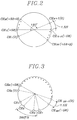
- FIG. 2 shows a plan view of the head drum assembly in accordance with the invention, which is capable of performing a multi-track scanning on the magnetic tape 20.
- the drum assembly 10 includes a head arrangement having a number of video heads CH1 to CH 2N which are installed along a circumferential outer surface of the rotating upper drum part 16.
- the number N corresponds to the speed multiplying factor of the tape transport mechanism 30.
- the video heads are divided into two groups. Each group has the N number of video heads, CH1 to CH N and CH N+1 to CH 2N, which are positioned closely adjacent one another at a predetermined space.
- the predetermined space is 1.5 H which corresponds to the distance between two adjacent track edges being aligned with their corresponding video heads, as can be seen from FIG. 4, wherein H represent a horizontal video line.
- the video heads CH1 to CH N in the first group are symmetrically opposite the video heads CH N+1 to CH 2N in the second group at an angle of 180°, respectively.
- the odd numbered video heads in each group have a first azimuth angle which is inclined in a first direction perpendicular to the head scanning direction while the even numbered video heads in each group have a second azimuth angle which is inclined in a second direction opposite the first direction, respectively. That is, the video heads take the first and the second azimuth angles in alternative fashion.
- the video heads CH1 to CH N and CH N+1 to CH 2N in each group are arranged in such a way that when an imaginary straight line passing therethrough will have a slope which be less than an angle of 0°. That is, the video heads CH1 to CH N and CH N+1 to CH 2N in each group are disposed at different heights stepwise upwardly from the bottom edge 24 of the drum assembly 10, but aligned with the travelling or longitudinal direction of the tape 20 wrapping on the drum assembly 10, thereby ensuring that the video heads simultaneously scan the corresponding number of tracks on the tape 20.
- the height corresponds to an effective width "W" of the track, i.e., 58 ⁇ m.
- the number in parentheses in FIG. 2 represents the stepwise height of the remaining video heads with respect to a leading video head CH1 or CH N+1 in the first or the second head group.
- the N video heads on the drum assembly 10 there is illustrated the relationship between the video heads on the drum assembly 10 and the tape 20.
- the tape 20 moves across the head drum assembly 10 at N times the standard speed, all of the N video heads CH1 to CH N in the first video head group lay down the lower edges of the corresponding N number of tracks and then scan the N tracks for a half-rotation of the head drum assembly 10.
- the N video heads CH N+1 to CH 2N in the second video head group simultaneously scan another N video tracks for a next half-rotation of the head drum assembly 10. Therefore, the N video heads in each group scan the respective corresponding N number of tracks on the magnetic tape 20 at a time during the duration of each pass of the head drum assembly 10, to thereby achieve the multi-track scanning of the magnetic tape 20.
- two helical scanning systems may be employed, one of which is used for reproducing the video signal prerecorded on a magnetic tape and the other is used for recording the reproduced video signal on a blank tape.
- FIG. 3 illustrates another preferred embodiment of the head arrangement of the head drum assembly in accordance with the invention.
- the head drum assembly 10 includes the head arrangement having N pairs of video heads, CH1 to CH 2N, arranged in such a manner that each pair of video heads is angularly separated from each other by 360°/N.
- Each of said N pairs contains a first and a second video heads which are disposed adjacent each other at a predetermined distance and have azimuth angles different from each other.
- the predetermined distance between the two video heads in each pair is also adjusted to 1.5 H as set forth above.
- the two video heads in each pair are disposed at a different height from the bottom edge 24 of the drum assembly 10, but aligned with the travelling or longitudinal direction of the tape 20 wrapping on the drum assembly 10. That is, the second video head CH2, CH4, CH6 or CH 2N in each pair is disposed at a different height above the first video head CH1, CH3, CH5 or CH 2N-1 in each pair.
- the different height corresponds to the effective width of the track, e.g, 58 ⁇ m.
- the numbers in parentheses in FIG. 3 represent the height between the first and the second video heads.
- FIG. 5 there is illustrates the relationship between the video heads on the drum assembly 10 for the second embodiment of the invention and the magnetic tape.
- the tape 20 moves across the head drum assembly 10 at N times the standard speed
- each video head pair sequentially lays down its corresponding pair of tracks to scan its corresponding tracks for each 360°/N rotation of the head drum assembly 10. Therefore, two tracks are traced by each pair of the video heads, to thereby reproduce N complete field video information during the period of each pass of the head drum assembly 10.
- the lead angle " ⁇ D " of the head drum assembly 10 should be changed as follows: wherein ⁇ T is the track angle inclined with respect to the longitudinal direction of the magnetic tape, W is the effective tape width, N is the speed multiplying factor and L is the distance of the tape movement per track.
- the diameter "D" of the head drum assembly 10 should also he changed.
- the drum diameter can be derived as: Accordingly, wherein D is the diameter of the drum assembly, N is the speed multiplying factor and ⁇ D is the lead angle of the drum assembly 10.
- the slant angle and the center coordinate for the slant posts 12 and 14 are also deformed to match with the configuration of the head drum assembly.
- One of the methods, for instance, is disclosed in an article by Nakamura Katsushi, "Design Method for a Tape Scanning System", Design and Estimation of a VTR Tape Scanning System , pp 11-14, published by Mastushita Electronics Co., Ltd. in Japan (April 30, 1990), which is incorporated herein by reference.
Abstract
Description
- The present invention relates to a helical scanning system for use in a video cassette recorder ("VCR"); and, more particularly, to a multi-track scanning system of a magnetic tape loaded in the VCR.
- In a VCR, a helical scanning system is normally employed to scan a magnetic tape through the use of a cylindrical rotatable drum assembly called "scanner" having a pair of video heads installed in a diametrically opposite relationship thereon for recording and/or reproducing a video signal.
- Each video head is in contact with the tape for each revolution of the drum assembly to record or reproduce on a per field basis.
- In such a helical scanning system, it is sometimes necessary to reproduce or record video signals at a high speed for the purpose of fast duplication. One of the important variables that control the duplication speed is the tape movement speed. The faster the tape movement speed is, the higher the duplication speed becomes. However, as the tape movement speed increases, the trajectory of the video heads tends to be misaligned with respect to their corresponding tracks on the tape due to the change in the relative speed between the tape and the video heads in contact with the tape. Therefore, there may occur cross talks caused by one of the video heads scanning a portion of its adjacent track. The cross talks in turn may produce a noise band in a reproduced picture.
- Another important variable is the number of the heads mounted on the drum assembly. Certain VCR models include an extra pair of video heads. For example, one of the multi-head VCR system disclosed in U.S.Patent No. 5,311,375 issued to Yoshiyuki Ikushima et al. includes a head arrangement on a drum assembly having a first and a second pairs of heads. The first pair of heads scans to form a first and a second tracks spaced apart by approximately one track width, and the second pair of heads scans to form a third and a fourth tracks spaced apart by approximately one track width and in an interlaced manner with the first and the second tracks. Such head arrangement may be useful in improving the quality of a reproduced picture in a special reproducing mode such as a still, fast forward, or cue mode.
- Accordingly, there exists a need to develop a technology capable of equipping a VCR with the ability to duplicate prerecorded video signals in a high speed without creating a noise band.
- It is, therefore, a primary object of the invention to provide a helical scanning apparatus capable of scanning a multiple number of video tracks to thereby achieve a high speed duplication.
- In accordance with a preferred embodiment of the present invention, there is provided a helical scanning apparatus for use in a video cassette recorder for scanning a multiple number of tracks on a magnetic tape, which comprises: a tape transport means for moving the magnetic tape at a speed as N times high as a standard tape movement speed, wherein said N is a speed multiplying factor and positive integer (N = 1, 2, 3,...); and a rotatable head drum assembly for scanning the magnetic tape guided at an angle to the head drum assembly, the drum assembly having 2N number of video heads thereon which are installed along a circumferential outer surface of the head drum assembly, the video heads being divided into two groups, each group having N video heads, the video heads in each group being positioned closely adjacent one another at a predetermined space and disposed at different heights stepwise upwardly along the rotating direction of the head drum assembly, but aligned with the longitudinal direction of the tape.
- In accordance with another embodiment of the present invention, there is provided a helical scanning apparatus for use in a video cassette recorder for scanning a multiple number of tracks on a magnetic tape, which comprises: a tape transport means for moving the magnetic tape at a speed as N times high as a standard tape movement speed, wherein said N is a speed factor and positive integer (N = 1, 2, 3,...); and a rotatable head drum assembly for scanning the magnetic tape guided at an angle to the head drum assembly, the drum assembly having N pairs of video heads thereon which are installed along a circumferential outer surface of the head drum assembly, said N pairs of video heads being arranged in such a manner that each pair of video heads is angularly separated from one another by 360°/N, each of the N pairs having a first and a second video heads which are disposed adjacent each other and the second video head in each pair is disposed at a predetermined height above the first video head in said pair along the rotating direction of the head drum assembly.
- The above and other objects and features of the present invention will become apparent from the following description of preferred embodiments taken in conjunction with the accompanying drawings, in which:
- FIG. 1 shows a conventional helical scanning system;
- FIG. 2 presents a top plan view of the head arrangement on the head drum assembly shown in FIG. 1 in accordance with the invention;
- FIG. 3 represents a top plan view of another embodiment of the head arrangement on the head drum assembly in accordance with the invention; and
- FIGs. 4 and 5 provide a diagrammatic view showing a track pattern on the magnetic tape traced by the head arrangement shown in FIGs. 2 and 3, respectively.
- Referring to FIG 1, there is shown a basic arrangement for a conventional helical scanning system to help explain the invention, wherein a
magnetic tape 20 is helically wound around a cylindricalhead drum assembly 10. - To facilitate the
tape 20 to enter and exit from thehead drum assembly 10, there are provided asupply slant post 12 at the left side used as an entrance guide for thehead drum assembly 10 and a take-up slant post 14 at the right side used as an exit guide for thehead drum assembly 10. Thesupply slant post 12 makes thetape 20 travel downward and the take-up slant post 14 sets the tape toward thetape transporting mechanism 30 including apinch roller 32 and acapstan 34. - The
head drum assembly 10 is divided into anupper drum part 16 and alower drum part 18. Theupper drum part 16 rotates counterclockwise and carries two video heads mounted on the lower surface thereof. The video heads are precisely 180° apart, opposite each other on the same diameter of thedrum assembly 10. They protrude slightly to press into the surface of thetape 20. Thelower part 18 of thedrum assembly 10 is stationary and has aguide band 22 machined into the surface thereof. Theguide band 22 serves to guide thetape 20 at an angle of, e.g., 5.93539° to thedrum assembly 10. The angle is called a "lead angle". - The video heads alternate in recording a sequence of video fields. Since a one-half turn takes approximately 1/60 second for one field, a full turn takes 1/30 second in the NTSC standard. The rotation speed, then, is 30 revolutions per second (rps), or 1800 revolutions per minute (rpm) for the
head drum assembly 10. - Since the
tape 20 is angled downward as it travels around thedrum assembly 10, each video head crosses the width of the tape at a shallow angle. Each path starts near the lower edge of the tape and finishes near the upper edge. - The
tape 20 is in contact with thehead drum assembly 10 wrapping a little more than 180° and thetape 20 moves along the guide band at a standard speed, e. g., 33.35 mm/sec, in a playback mode or recording mode, through the use of thetape transport mechanism 30 including thepinch roller 32 and thecapstan 34. Magnetic recording and/or reproducing is made on diagonal paths or tracks across the tape as the tape travels across the heads at the lead angle. As is well known in the art, the track is inclined at an angle of, e.g., 5.9694° with respect to the longitudinal direction of themagnetic tape 20. On each inclined track, there is a single vertical field containing 262.5 horizontal lines ("262.5H") of video information, in case of the NTSC standard. - In accordance with the invention, the
tape transport mechanism 30 is designed to move themagnetic tape 20 at a faster speed than the standard speed. That is, thetape transport mechanism 30 advances the magnetic tape at a speed as N times high as the standard speed on reproducing a prerecorded video signal or recording the reproduced video signal for the purpose of high speed duplication wherein N is a speed multiplying factor and positive integer (N = 1, 2, 3,...). Thehead drum assembly 10 adapted to scan themagnetic tape 20 running at N times the standard speed will be described with reference to FIGs. 2 and 4 as follows. - FIG. 2 shows a plan view of the head drum assembly in accordance with the invention, which is capable of performing a multi-track scanning on the
magnetic tape 20. - The
drum assembly 10 includes a head arrangement having a number of video heads CH₁ to CH2N which are installed along a circumferential outer surface of the rotatingupper drum part 16. The number N corresponds to the speed multiplying factor of thetape transport mechanism 30. - The video heads are divided into two groups. Each group has the N number of video heads, CH₁ to CHN and CHN+1 to CH2N, which are positioned closely adjacent one another at a predetermined space. The predetermined space is 1.5 H which corresponds to the distance between two adjacent track edges being aligned with their corresponding video heads, as can be seen from FIG. 4, wherein H represent a horizontal video line. In addition, the video heads CH₁ to CHN in the first group are symmetrically opposite the video heads CHN+1 to CH2N in the second group at an angle of 180°, respectively. The odd numbered video heads in each group have a first azimuth angle which is inclined in a first direction perpendicular to the head scanning direction while the even numbered video heads in each group have a second azimuth angle which is inclined in a second direction opposite the first direction, respectively. That is, the video heads take the first and the second azimuth angles in alternative fashion.
- Further, as best shown in FIG. 4, the video heads CH₁ to CHN and CHN+1 to CH2N in each group are arranged in such a way that when an imaginary straight line passing therethrough will have a slope which be less than an angle of 0°. That is, the video heads CH₁ to CHN and CHN+1 to CH2N in each group are disposed at different heights stepwise upwardly from the
bottom edge 24 of thedrum assembly 10, but aligned with the travelling or longitudinal direction of thetape 20 wrapping on thedrum assembly 10, thereby ensuring that the video heads simultaneously scan the corresponding number of tracks on thetape 20. The height corresponds to an effective width "W" of the track, i.e., 58µm. The number in parentheses in FIG. 2 represents the stepwise height of the remaining video heads with respect to a leading video head CH₁ or CHN+1 in the first or the second head group. - Referring to FIG. 4, there is illustrated the relationship between the video heads on the
drum assembly 10 and thetape 20. As thetape 20 moves across thehead drum assembly 10 at N times the standard speed, all of the N video heads CH₁ to CHN in the first video head group lay down the lower edges of the corresponding N number of tracks and then scan the N tracks for a half-rotation of thehead drum assembly 10. At a next time when themagnetic tape 20 advances to a position at which the second video head group is located, the N video heads CHN+1 to CH2N in the second video head group simultaneously scan another N video tracks for a next half-rotation of thehead drum assembly 10. Therefore, the N video heads in each group scan the respective corresponding N number of tracks on themagnetic tape 20 at a time during the duration of each pass of thehead drum assembly 10, to thereby achieve the multi-track scanning of themagnetic tape 20. - If it is required to duplicate the video signal at a higher speed, two helical scanning systems may be employed, one of which is used for reproducing the video signal prerecorded on a magnetic tape and the other is used for recording the reproduced video signal on a blank tape.
- FIG. 3 illustrates another preferred embodiment of the head arrangement of the head drum assembly in accordance with the invention. The
head drum assembly 10 includes the head arrangement having N pairs of video heads, CH₁ to CH2N, arranged in such a manner that each pair of video heads is angularly separated from each other by 360°/N. - Each of said N pairs contains a first and a second video heads which are disposed adjacent each other at a predetermined distance and have azimuth angles different from each other. The predetermined distance between the two video heads in each pair is also adjusted to 1.5 H as set forth above.
- Further, as best shown in FIG. 5, the two video heads in each pair are disposed at a different height from the
bottom edge 24 of thedrum assembly 10, but aligned with the travelling or longitudinal direction of thetape 20 wrapping on thedrum assembly 10. That is, the second video head CH₂, CH₄, CH₆ or CH2N in each pair is disposed at a different height above the first video head CH₁, CH₃, CH₅ or CH2N-1 in each pair. The different height corresponds to the effective width of the track, e.g, 58µm. The numbers in parentheses in FIG. 3 represent the height between the first and the second video heads. - Referring to FIG. 5, there is illustrates the relationship between the video heads on the
drum assembly 10 for the second embodiment of the invention and the magnetic tape. As thetape 20 moves across thehead drum assembly 10 at N times the standard speed, each video head pair sequentially lays down its corresponding pair of tracks to scan its corresponding tracks for each 360°/N rotation of thehead drum assembly 10. Therefore, two tracks are traced by each pair of the video heads, to thereby reproduce N complete field video information during the period of each pass of thehead drum assembly 10. - As the tape movement speed increases, the trajectory of the video heads tends to have a slope which will be greater than the track angle. Therefore, in order to allow the video heads to exactly trace the corresponding tracks on the
magnetic tape 20, the lead angle "ϑD" of thehead drum assembly 10 should be changed as follows:
wherein ϑT is the track angle inclined with respect to the longitudinal direction of the magnetic tape, W is the effective tape width, N is the speed multiplying factor and L is the distance of the tape movement per track. - Further, since the lead angle is different from a conventional lead angle, the diameter "D" of the
head drum assembly 10 should also he changed. The drum diameter can be derived as:
Accordingly,
wherein D is the diameter of the drum assembly, N is the speed multiplying factor and ϑD is the lead angle of thedrum assembly 10. - In this connection, it should be noted that the slant angle and the center coordinate for the slant posts 12 and 14 are also deformed to match with the configuration of the head drum assembly. There are well known methods in the art to derive the slant angle and the center coordinate. One of the methods, for instance, is disclosed in an article by Nakamura Katsushi, "Design Method for a Tape Scanning System", Design and Estimation of a VTR Tape Scanning System, pp 11-14, published by Mastushita Electronics Co., Ltd. in Japan (April 30, 1990), which is incorporated herein by reference.
- While the present invention has been shown and described with respect to the preferred embodiments, it will be apparent to those skilled in the art that many changes and modifications may be made without departing from the spirit and scope of the invention as defined in the appended claims.
Claims (12)
- A helical scanning apparatus for use in a video cassette recorder adapted for scanning a multiple number of tracks on a magnetic tape, which comprises:
a tape transport means for moving the magnetic tape at a speed as N times high as a standard tape movement speed, wherein said N is a speed multiplying factor and positive integer; and
a rotatable head drum assembly for scanning the magnetic tape guided at an angle to the head drum assembly, the drum assembly having 2N number of video heads thereon which are installed along a circumferential outer surface of the head drum assembly, the video heads being divided into two groups, each group having N video heads, the video heads in each group being positioned closely adjacent one another at a predetermined space and having azimuth angles different from each other in an alternative fashion, and the N video heads in a first group being symmetrically opposite the N video heads in a second group along the rotating direction of the drum assembly. - The apparatus as recited in claim 1, wherein the video heads in each group are disposed at different heights stepwise upwardly from the bottom edge of the drum assembly.
- The apparatus as recited in claim 2, wherein the height between the adjacent video heads corresponds to the effective width of a track on the magnetic tape.
- The apparatus as recited in claim 1, wherein the predetermined space corresponds to a distance between two adjacent track edges on the magnetic tape being aligned with their corresponding video heads.
- The apparatus as recited in claim 1, wherein the angle (ϑD) to the drum assembly is defined as:
- The apparatus as recited in claim 5, wherein the diameter (D) of the drum assembly is defined as:

- A helical scanning apparatus for use in a video cassette recorder adapted for scanning a multiple number of tracks on a magnetic tape, which comprises:
a tape transport means for moving the magnetic tape at a speed as N times high as a standard tape movement speed, wherein said N is a speed multiplying factor and positive integer; and
a rotatable head drum assembly for scanning the magnetic tape guided at an angle to the head drum assembly, the drum assembly having 2N number of video heads thereon which are installed along a circumferential outer surface of the head drum assembly, the N pairs of video heads being arranged in such a manner that each pair of video heads is angularly separated from one another by 360°/N, and each pair having a first and a second video heads which are disposed adjacent each other at a predetermined space and have azimuth angles different from each other. - The apparatus as recited in claim 7, wherein the two video heads in each pair are disposed at a different height from the bottom edge of the drum assembly.
- The apparatus as recited in claim 8, wherein the height between the two video heads corresponds to the effective width of a track.
- The apparatus as recited in claim 7, wherein the predetermined space corresponds to the distance between two adjacent track edges being aligned with their corresponding video heads.
- The apparatus as recited in claim 7, wherein the angle (ϑD) to the head drum assembly is defined as:

- The apparatus as recited in claim 11, wherein the diameter (D) of the drum assembly is defined as:

Applications Claiming Priority (2)
| Application Number | Priority Date | Filing Date | Title |
|---|---|---|---|
| KR1019930024386A KR960003700B1 (en) | 1993-11-16 | 1993-11-16 | Deck of vcr for double speed copy |
| KR9324386 | 1993-11-16 |
Publications (3)
| Publication Number | Publication Date |
|---|---|
| EP0653745A2 true EP0653745A2 (en) | 1995-05-17 |
| EP0653745A3 EP0653745A3 (en) | 1995-11-02 |
| EP0653745B1 EP0653745B1 (en) | 2001-08-22 |
Family
ID=19368209
Family Applications (1)
| Application Number | Title | Priority Date | Filing Date |
|---|---|---|---|
| EP94115974A Expired - Lifetime EP0653745B1 (en) | 1993-11-16 | 1994-10-10 | Multi-track helical scanning system |
Country Status (6)
| Country | Link |
|---|---|
| US (1) | US5835301A (en) |
| EP (1) | EP0653745B1 (en) |
| JP (1) | JPH07192204A (en) |
| KR (1) | KR960003700B1 (en) |
| CN (1) | CN1038071C (en) |
| DE (1) | DE69428021T2 (en) |
Cited By (2)
| Publication number | Priority date | Publication date | Assignee | Title |
|---|---|---|---|---|
| EP0653746A2 (en) * | 1993-11-16 | 1995-05-17 | Daewoo Electronics Co., Ltd | Multi-track helical scanning system |
| DE19648502A1 (en) * | 1995-11-23 | 1997-05-28 | Samsung Electronics Co Ltd | Digital recording and reproducing apparatus for high-speed copying a tape |
Citations (7)
| Publication number | Priority date | Publication date | Assignee | Title |
|---|---|---|---|---|
| JPS6449112A (en) * | 1987-08-19 | 1989-02-23 | Mitsubishi Electric Corp | Video signal recording and reproducing device |
| JPH01277304A (en) * | 1988-04-28 | 1989-11-07 | Canon Inc | Rotary head type recording or reproducing device |
| JPH01296411A (en) * | 1988-05-25 | 1989-11-29 | Canon Inc | Rotary head type recording or reproducing device |
| US4897739A (en) * | 1986-04-07 | 1990-01-30 | Canon Kabushiki Kaisha | Multi-channel recording apparatus using a plurality of heads in turn |
| JPH02206013A (en) * | 1989-02-03 | 1990-08-15 | Matsushita Electric Ind Co Ltd | Magnetic recording and reproducing device and reproducing combination head |
| JPH04195789A (en) * | 1990-11-26 | 1992-07-15 | Matsushita Electric Ind Co Ltd | Magnetic recording and reproducing device |
| JPH05174304A (en) * | 1991-12-24 | 1993-07-13 | Nec Gumma Ltd | Vtr for rec0rding and reproducing two channels simultaneously |
Family Cites Families (7)
| Publication number | Priority date | Publication date | Assignee | Title |
|---|---|---|---|---|
| US4167023A (en) * | 1976-06-09 | 1979-09-04 | Rca Corporation | Rotating head recorder with different recording and playback speeds |
| JPS58105675A (en) * | 1981-12-18 | 1983-06-23 | Victor Co Of Japan Ltd | Video signal recording device |
| JPS60142847U (en) * | 1984-03-05 | 1985-09-21 | 日本ビクター株式会社 | Magnetic tape recording/reproducing device |
| US4888653A (en) * | 1987-12-28 | 1989-12-19 | Eastman Kodak Company | High speed video tape duplicator |
| JPH0817471B2 (en) * | 1988-05-31 | 1996-02-21 | シャープ株式会社 | Head device for video signal recording / reproducing apparatus |
| JPH0384701A (en) * | 1989-08-28 | 1991-04-10 | Sharp Corp | Helical scan type recorder for magnetic tape |
| EP0581307B1 (en) * | 1992-07-31 | 1999-10-06 | Canon Kabushiki Kaisha | Recording and/or reproducing apparatus having rotary heads |
-
1993
- 1993-11-16 KR KR1019930024386A patent/KR960003700B1/en not_active IP Right Cessation
-
1994
- 1994-10-10 DE DE69428021T patent/DE69428021T2/en not_active Expired - Fee Related
- 1994-10-10 EP EP94115974A patent/EP0653745B1/en not_active Expired - Lifetime
- 1994-10-11 US US08/320,630 patent/US5835301A/en not_active Expired - Fee Related
- 1994-10-14 JP JP6249274A patent/JPH07192204A/en active Pending
- 1994-11-16 CN CN94118399A patent/CN1038071C/en not_active Expired - Fee Related
Patent Citations (7)
| Publication number | Priority date | Publication date | Assignee | Title |
|---|---|---|---|---|
| US4897739A (en) * | 1986-04-07 | 1990-01-30 | Canon Kabushiki Kaisha | Multi-channel recording apparatus using a plurality of heads in turn |
| JPS6449112A (en) * | 1987-08-19 | 1989-02-23 | Mitsubishi Electric Corp | Video signal recording and reproducing device |
| JPH01277304A (en) * | 1988-04-28 | 1989-11-07 | Canon Inc | Rotary head type recording or reproducing device |
| JPH01296411A (en) * | 1988-05-25 | 1989-11-29 | Canon Inc | Rotary head type recording or reproducing device |
| JPH02206013A (en) * | 1989-02-03 | 1990-08-15 | Matsushita Electric Ind Co Ltd | Magnetic recording and reproducing device and reproducing combination head |
| JPH04195789A (en) * | 1990-11-26 | 1992-07-15 | Matsushita Electric Ind Co Ltd | Magnetic recording and reproducing device |
| JPH05174304A (en) * | 1991-12-24 | 1993-07-13 | Nec Gumma Ltd | Vtr for rec0rding and reproducing two channels simultaneously |
Non-Patent Citations (6)
| Title |
|---|
| PATENT ABSTRACTS OF JAPAN vol. 013 no. 250 (P-882) ,12 June 1989 & JP-A-01 049112 (MITSUBISHI ELECTRIC CORP) 23 February 1989, * |
| PATENT ABSTRACTS OF JAPAN vol. 014 no. 048 (P-0997) ,29 January 1990 & JP-A-01 277304 (CANON INC) 7 November 1989, * |
| PATENT ABSTRACTS OF JAPAN vol. 014 no. 084 (P-1007) ,16 February 1990 & JP-A-01 296411 (CANON INC) 29 November 1989, * |
| PATENT ABSTRACTS OF JAPAN vol. 014 no. 500 (P-1125) ,31 October 1990 & JP-A-02 206013 (MATSUSHITA ELECTRIC IND CO LTD) 15 August 1990, * |
| PATENT ABSTRACTS OF JAPAN vol. 016 no. 527 (P-1447) ,29 October 1992 & JP-A-04 195789 (MATSUSHITA ELECTRIC IND CO LTD) 15 July 1992, * |
| PATENT ABSTRACTS OF JAPAN vol. 017 no. 590 (P-1635) ,27 October 1993 & JP-A-05 174304 (NEC GUMMA LTD) 13 July 1993, * |
Cited By (4)
| Publication number | Priority date | Publication date | Assignee | Title |
|---|---|---|---|---|
| EP0653746A2 (en) * | 1993-11-16 | 1995-05-17 | Daewoo Electronics Co., Ltd | Multi-track helical scanning system |
| EP0653746A3 (en) * | 1993-11-16 | 1996-02-28 | Daewoo Electronics Co Ltd | Multi-track helical scanning system. |
| DE19648502A1 (en) * | 1995-11-23 | 1997-05-28 | Samsung Electronics Co Ltd | Digital recording and reproducing apparatus for high-speed copying a tape |
| US5986829A (en) * | 1995-11-23 | 1999-11-16 | Samsung Electronics Co., Ltd. | Digital recording and reproducing apparatus for high-speed copying of tape |
Also Published As
| Publication number | Publication date |
|---|---|
| EP0653745B1 (en) | 2001-08-22 |
| DE69428021D1 (en) | 2001-09-27 |
| KR960003700B1 (en) | 1996-03-21 |
| KR950015277A (en) | 1995-06-16 |
| CN1038071C (en) | 1998-04-15 |
| JPH07192204A (en) | 1995-07-28 |
| CN1126870A (en) | 1996-07-17 |
| DE69428021T2 (en) | 2001-12-06 |
| US5835301A (en) | 1998-11-10 |
| EP0653745A3 (en) | 1995-11-02 |
Similar Documents
| Publication | Publication Date | Title |
|---|---|---|
| US3157739A (en) | Signal recording and reproducing system | |
| US4424541A (en) | Apparatus and method for multi-track recording of a digital signal | |
| GB1579780A (en) | Apparatus for reproducing signals on a magnetic tape | |
| KR960705308A (en) | Apparatus for recording and / or reproducing video signals and audio signals in / form inclined tracks on a magnetic tape, and magnetic tape for such apparatus | |
| US3391248A (en) | System and apparatus for recording and reproducing television video signals | |
| US4075666A (en) | Magnetic tape recorder | |
| US4314284A (en) | Video head deflection apparatus for special motion reproduction by helical scan VTR | |
| US4535367A (en) | Magnetic record still mode reproduction apparatus and method | |
| US4890169A (en) | Magnetic tape recording and/or reproducing apparatus with slow motion effect | |
| US5835301A (en) | Multi-track helical scanning system | |
| EP0344754A3 (en) | Video tape recorder | |
| US3215772A (en) | Magnetic recording of signals containing synchronizing information | |
| US4580180A (en) | Method of and apparatus for scanning tape with scanning head | |
| US5870240A (en) | Video cassette recorder having posts movable vertically | |
| EP0653746A2 (en) | Multi-track helical scanning system | |
| KR950000947B1 (en) | Method of scanning a helical scan record | |
| USRE29999E (en) | System and apparatus for recording and reproducing television video signals | |
| JP3249259B2 (en) | Digital signal recording device and reproducing device | |
| KR920006907Y1 (en) | Drum with control head | |
| JPH0377563B2 (en) | ||
| JPS58220202A (en) | Magnetic recording and reproducing device | |
| KR910009466B1 (en) | Head drum assembly for vtr | |
| JP3161051B2 (en) | Magnetic recording / reproducing device | |
| KR0147795B1 (en) | Recording and reproducing apparatus | |
| JPH0540901A (en) | Device and method for magnetic recording |
Legal Events
| Date | Code | Title | Description |
|---|---|---|---|
| PUAI | Public reference made under article 153(3) epc to a published international application that has entered the european phase |
Free format text: ORIGINAL CODE: 0009012 |
|
| AK | Designated contracting states |
Kind code of ref document: A2 Designated state(s): DE FR GB NL |
|
| PUAL | Search report despatched |
Free format text: ORIGINAL CODE: 0009013 |
|
| AK | Designated contracting states |
Kind code of ref document: A3 Designated state(s): DE FR GB NL |
|
| 17P | Request for examination filed |
Effective date: 19960430 |
|
| 17Q | First examination report despatched |
Effective date: 19980518 |
|
| GRAG | Despatch of communication of intention to grant |
Free format text: ORIGINAL CODE: EPIDOS AGRA |
|
| GRAG | Despatch of communication of intention to grant |
Free format text: ORIGINAL CODE: EPIDOS AGRA |
|
| GRAH | Despatch of communication of intention to grant a patent |
Free format text: ORIGINAL CODE: EPIDOS IGRA |
|
| GRAH | Despatch of communication of intention to grant a patent |
Free format text: ORIGINAL CODE: EPIDOS IGRA |
|
| GRAA | (expected) grant |
Free format text: ORIGINAL CODE: 0009210 |
|
| AK | Designated contracting states |
Kind code of ref document: B1 Designated state(s): DE FR GB NL |
|
| REF | Corresponds to: |
Ref document number: 69428021 Country of ref document: DE Date of ref document: 20010927 |
|
| ET | Fr: translation filed | ||
| REG | Reference to a national code |
Ref country code: GB Ref legal event code: IF02 |
|
| PLBE | No opposition filed within time limit |
Free format text: ORIGINAL CODE: 0009261 |
|
| STAA | Information on the status of an ep patent application or granted ep patent |
Free format text: STATUS: NO OPPOSITION FILED WITHIN TIME LIMIT |
|
| 26N | No opposition filed | ||
| REG | Reference to a national code |
Ref country code: GB Ref legal event code: 732E |
|
| NLS | Nl: assignments of ep-patents |
Owner name: DAEWOO ELECTRONICS CORPORATION |
|
| REG | Reference to a national code |
Ref country code: FR Ref legal event code: TP |
|
| PGFP | Annual fee paid to national office [announced via postgrant information from national office to epo] |
Ref country code: FR Payment date: 20031003 Year of fee payment: 10 |
|
| PGFP | Annual fee paid to national office [announced via postgrant information from national office to epo] |
Ref country code: NL Payment date: 20031008 Year of fee payment: 10 Ref country code: GB Payment date: 20031008 Year of fee payment: 10 |
|
| PGFP | Annual fee paid to national office [announced via postgrant information from national office to epo] |
Ref country code: DE Payment date: 20031023 Year of fee payment: 10 |
|
| PG25 | Lapsed in a contracting state [announced via postgrant information from national office to epo] |
Ref country code: GB Free format text: LAPSE BECAUSE OF NON-PAYMENT OF DUE FEES Effective date: 20041010 |
|
| PG25 | Lapsed in a contracting state [announced via postgrant information from national office to epo] |
Ref country code: NL Free format text: LAPSE BECAUSE OF NON-PAYMENT OF DUE FEES Effective date: 20050501 |
|
| PG25 | Lapsed in a contracting state [announced via postgrant information from national office to epo] |
Ref country code: DE Free format text: LAPSE BECAUSE OF NON-PAYMENT OF DUE FEES Effective date: 20050503 |
|
| GBPC | Gb: european patent ceased through non-payment of renewal fee |
Effective date: 20041010 |
|
| PG25 | Lapsed in a contracting state [announced via postgrant information from national office to epo] |
Ref country code: FR Free format text: LAPSE BECAUSE OF NON-PAYMENT OF DUE FEES Effective date: 20050630 |
|
| NLV4 | Nl: lapsed or anulled due to non-payment of the annual fee |
Effective date: 20050501 |
|
| REG | Reference to a national code |
Ref country code: FR Ref legal event code: ST |