EP0652523A1 - Système de surveillance à distance - Google Patents
Système de surveillance à distance Download PDFInfo
- Publication number
- EP0652523A1 EP0652523A1 EP94308270A EP94308270A EP0652523A1 EP 0652523 A1 EP0652523 A1 EP 0652523A1 EP 94308270 A EP94308270 A EP 94308270A EP 94308270 A EP94308270 A EP 94308270A EP 0652523 A1 EP0652523 A1 EP 0652523A1
- Authority
- EP
- European Patent Office
- Prior art keywords
- level
- polling
- data
- monitored
- station
- Prior art date
- Legal status (The legal status is an assumption and is not a legal conclusion. Google has not performed a legal analysis and makes no representation as to the accuracy of the status listed.)
- Granted
Links
Images


Classifications
-
- G—PHYSICS
- G06—COMPUTING; CALCULATING OR COUNTING
- G06F—ELECTRIC DIGITAL DATA PROCESSING
- G06F13/00—Interconnection of, or transfer of information or other signals between, memories, input/output devices or central processing units
- G06F13/14—Handling requests for interconnection or transfer
- G06F13/20—Handling requests for interconnection or transfer for access to input/output bus
- G06F13/22—Handling requests for interconnection or transfer for access to input/output bus using successive scanning, e.g. polling
- G06F13/225—Handling requests for interconnection or transfer for access to input/output bus using successive scanning, e.g. polling with priority control
-
- H—ELECTRICITY
- H04—ELECTRIC COMMUNICATION TECHNIQUE
- H04Q—SELECTING
- H04Q9/00—Arrangements in telecontrol or telemetry systems for selectively calling a substation from a main station, in which substation desired apparatus is selected for applying a control signal thereto or for obtaining measured values therefrom
Definitions
- the present invention relates to a remote monitoring system, and more particularly to a remote monitoring system having a centralized monitoring station for collecting data from a plurality of monitored stations that are connected to a bus network.
- Conventional remote monitoring systems employ a polling process as a data collecting process for requesting all monitored stations to transmit data.
- a polling process all the monitored stations are polled in the same manner irrespective of the condition of the monitored stations.
- the time established by the remote monitoring system to collect data from all the monitored stations is determined by the sum of times required to collect data from the individual monitored stations. If the proportion of data of less importance is large in the amount of data to be transmitted from the monitored stations and if there is even one monitored station which transmits a large amount of data, then the remote monitoring system needs a long period of time to collect the data.
- Japanese patent laid-open No. 270426/90 discloses a communication control system in which monitoring information is given preferential ranking, and stored in a plurality of registers according to the given preferential ranking, so that emergency information can be transmitted and received more quickly than the other information.
- Japanese patent laid-open No. 75146/92 discloses a centralized monitoring control system in which each monitored station is polled for confirming an amount of data to be transmitted therefrom, and the number of times that each monitored station is to be polled is determined on the basis of the result of polling.
- the communication control system disclosed in the former publication is disadvantageous because it fails to handle any monitor information which is given priority ranking in excess of the number of transmission and reception registers that are installed.
- the centralized monitoring control system disclosed in the latter publication also has a problem in that it requires an extra period of time to effect polling on all the monitored stations to check the amount of data to be transmitted therefrom.
- Preferred embodiments of the present invention provide a remote monitoring system capable of collecting data efficiently by preferentially handling data of greater importance.
- a remote monitoring system comprising a plurality of monitored stations connected to a bus network, and a centralized monitoring station for collecting data from the plurality of monitored stations, each of the monitored stations comprising status/alarm detecting means for detecting a status and an alarm in the monitored station itself, condition memory means for storing a condition of the monitored station itself from the detected status and the detected alarm, level setting means for setting a request data level for transmission data of the monitored station itself based on the stored condition of the monitored station itself, and data transmitting/receiving means responsive to a data transmission request from the centralized monitoring station for updating the tranmission data level of the monitored station itself, and transmitting the transmission data level and transmission data having the transmission data level to the centralized monitoring station, the centralized monitoring station comprising data transmitting/receiving means for transmitting data to and receiving data from the monitored stations, a polling level table for holding polling levels corresponding to the monitored stations, respectively, calculated from the transmission data level of the transmission data from each of the monitored stations and the request
- Data of greater importance can be collected preferentially by varying the polling levels to be transmitted from the centralized monitoring station to the monitored stations depending on request data levels owned by the respective monitored stations on the network.
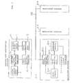
- a remote monitoring system comprises a plurality of monitored stations 2-1, 2-2, , 2-N on a network and a centralized monitoring station 1 for monitoring the monitored stations 2-1, 2-2, , 2-N.
- the monitored station 2-1 comprises a data transmitter/receiver 20-1 for transmitting data to and receiving data from the centralized monitoring station 1, a status/alarm detector 21-1 for detecting a status and an alarm in the monitored station 2-1 itself, a condition memory 22-1 for storing the condition of the monitored station 2-1 itself, a level setting unit 23-1 for setting a request data level for transmission data of the monitored station 2-1 itself based on the content of the condition memory 22-1, and a level memory 24-1 for storing transmission data levels and request data level for transmission data.
- the other monitored stations 2-2 ⁇ 2-N are identical in structure to the monitored station 2-1.
- a transmission data level of transmission data received from each of the monitored stations 2-i 1 ⁇ N) is represented by Lsd
- a request data level indicative of the transmission data level of transmission data held by each of the monitored stations 2-i is represented by Lsr
- a polling level transmitted to each of the monitored stations 2-i is represented by Ln
- a polling level stored in the polling level table 11 is represented by Lmr.
- the value of the transmission data level Lsd is equal to 1 when it is of a highest level, and becomes greater than 1 as the level becomes lowerer. This holds true for the values of Lsr, Ln, Lm and Lmr.
- the polling level table 11 stores polling levels Lmr that are calculated from transmission data levels Lsd and request data levels Lsr added to transmission data received from the monitored stations 2-i.
- the data transmitter/receiver 10 adds a polling level Ln that has been determined based on the contents of the polling level table 11 and the monitored station number table 14 by the polling level determining unit 13, to a polling packet, and transmits the polling packet with the added polling level Ln to each of the monitored stations 2-i.
- the polling level determining unit 13 determines from the polling level table 11 a monitored station/stations to be polled with a polling level equal to or greater than 2 in the next polling cycle, every time one polling cycle is completed. Specifically, in the case of one monitored station with a request data level equal to or greater than 2, the polling level determining unit 13 stores the number of the monitored station in the monitored station number table 14.
- the polling level determining unit 13 inspects the request data level of the monitored station 2-4, 2-5, ---, 2-N, 2-1 and 2-2 in this order.
- the data transmitter/receiver 20-i determines the request data level Lsr based on the content of the level memory 24-i, adds a request data level Lsr and a transmission data level Lsd to a response data packet, and transmits the response data packet with the added request data level Lsr and transmission data level Lsd to the centralized monitoring station 1.
- the centralized monitoring station 1 sends a data request to each of the monitored stations 2-i with a polling level Ln that has been determined based on the polling level Lmr which has been stored in the polling level table 11 in the above process.
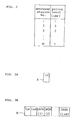
- FIG. 2 shows an arrangement of the polling level table 11.
- the polling level table 11 stores polling levels Lmr of "1", “2", "3", assigned respectively to the monitored station numbers 1 ⁇ N of the respective monitored stations 2-i.
- FIGS. 3A and 3B illustrate formats of data transmitted and received between the centralized monitoring station 1 and the monitored stations 2-i.
- FIG. 3A shows a polling packet A transmitted from the centralized monitoring station 1 to the monitored stations 2-i
- FIG. 3B shows a response data packet B transmitted from the monitored stations 2-i to the centralized monitoring station 1.
- the polling level Ln that has been determined by the polling level determining unit 13 is added to the polling packet A.
- the request data level Lsr and the transmission data level Lsd are added to data DATA(1) ⁇ DATA(Lsd) of the response data packet B which are transmitted to the centralized monitoring station 1.
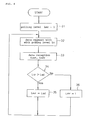
- FIG. 4 shows an operation sequence of the centralized monitoring station 1.
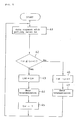
- FIG. 5 shows an operation sequence of each of the monitored stations 2-i.
- FIG. 6 shows a time sequence at the time the request data level Lsr of a monitored station 2-i varies, and
- FIG. 7 shows another time sequence at the time the request data level Lsr of a monitored station 2-i varies.
- the data transmitter/receiver 20-i of each of the monitored stations 2-i determines whether the request data level Lsr is Lsr ⁇ Ln + 1 or not in a step 42 shown in FIG. 5.
- the data transmitter/receiver 10 of the centralized monitoring station 1 Upon reception of the response data packet B from the data transmitter/receiver 20-i of each of the monitored stations 2-i in a step 33 shown in FIG. 4, the data transmitter/receiver 10 of the centralized monitoring station 1 outputs the request data level Lsr and the transmission data level Lsd that have been added to the response data packet B to the level rewriting unit 12.
- the level rewriting unit 12 determines whether the request data level Lsr received from the data transmitter/receiver 10 is greater than the transmission data level Lsd also received from the data transmitter/receiver 10 or not (Lsr > Lsd) in a step 34 shown in FIG. 4. If the request data level Lsr is greater than the transmission data level Lsd, then the level rewriting unit 12 writes a polling level Lmr as being equal to the transmission data level Lsd in the polling level table 11 in a step 35 shown in FIG. 4.
- the data transmitter/receiver 20-1 determines the request data level Lsr based on the stored content of the level memory 24-1 (see S1 in FIG. 6).
Applications Claiming Priority (2)
| Application Number | Priority Date | Filing Date | Title |
|---|---|---|---|
| JP304687/93 | 1993-11-10 | ||
| JP30468793 | 1993-11-10 |
Publications (2)
| Publication Number | Publication Date |
|---|---|
| EP0652523A1 true EP0652523A1 (fr) | 1995-05-10 |
| EP0652523B1 EP0652523B1 (fr) | 1999-06-02 |
Family
ID=17936016
Family Applications (1)
| Application Number | Title | Priority Date | Filing Date |
|---|---|---|---|
| EP94308270A Expired - Lifetime EP0652523B1 (fr) | 1993-11-10 | 1994-11-09 | Système de surveillance à distance |
Country Status (3)
| Country | Link |
|---|---|
| US (1) | US5586056A (fr) |
| EP (1) | EP0652523B1 (fr) |
| JP (1) | JP2836505B2 (fr) |
Cited By (3)
| Publication number | Priority date | Publication date | Assignee | Title |
|---|---|---|---|---|
| WO1999026155A1 (fr) * | 1997-11-13 | 1999-05-27 | Virata Limited | Gestion de peripheriques |
| EP1282266A2 (fr) * | 2001-07-31 | 2003-02-05 | Nec Corporation | Système de surveillance de paquets |
| EP1296484A1 (fr) * | 2001-09-20 | 2003-03-26 | Samsung Electronics Co., Ltd. | Procédé de communication de données utilisant un contrôle de nombres "backoff" et station pour appliquer la méthode |
Families Citing this family (11)
| Publication number | Priority date | Publication date | Assignee | Title |
|---|---|---|---|---|
| DE9421765U1 (de) * | 1994-08-19 | 1996-07-25 | Siemens Ag | Anordnung mit einer Signalverarbeitungsanschaltung und einer Funktionseinheit |
| FR2732788B1 (fr) * | 1995-04-06 | 1997-05-30 | Bull Sa | Dispositif de gestion d'appels selectifs cycliques pour la surveillance de ressources informatiques dans un reseau et procede mis en oeuvre par un tel dispositif |
| US5638299A (en) * | 1995-06-22 | 1997-06-10 | Miller; Keith | Light weight, self-contained programmable data-acquisition system |
| US7054919B2 (en) * | 2001-06-15 | 2006-05-30 | Ei3 Corporation | System and method for providing virtual online engineering of a production environment |
| US20060089977A1 (en) * | 2001-06-15 | 2006-04-27 | Spencer Cramer | System and method for providing virtual online engineering of a production environment |
| CN100351824C (zh) * | 2001-09-27 | 2007-11-28 | Nxp股份有限公司 | 总线系统和用于连接到总线的总线接口 |
| JP2005504393A (ja) * | 2001-09-27 | 2005-02-10 | コーニンクレッカ フィリップス エレクトロニクス エヌ ヴィ | バス・システムおよびバス・インターフェース |
| US6990479B2 (en) * | 2001-10-04 | 2006-01-24 | Samsung Electronics Co., Ltd. | Communication system and method of non-intrusive performance data polling |
| JP2008077535A (ja) * | 2006-09-25 | 2008-04-03 | Yokogawa Electric Corp | フィールド通信システム、フィールドサーバ、フィールド機器およびフィールド通信方法 |
| US20090073889A1 (en) * | 2007-09-19 | 2009-03-19 | Agere Systems Inc. | Phy bandwidth estimation from backpressure patterns |
| JP2009238001A (ja) * | 2008-03-27 | 2009-10-15 | Texas Instr Japan Ltd | コンピュータシステム |
Citations (3)
| Publication number | Priority date | Publication date | Assignee | Title |
|---|---|---|---|---|
| US4598363A (en) * | 1983-07-07 | 1986-07-01 | At&T Bell Laboratories | Adaptive delayed polling of sensors |
| US4638428A (en) * | 1983-12-14 | 1987-01-20 | Hitachi, Ltd. | Polling control method and system |
| JPH0475146A (ja) * | 1990-07-17 | 1992-03-10 | Nec Corp | 集中監視制御方式 |
Family Cites Families (12)
| Publication number | Priority date | Publication date | Assignee | Title |
|---|---|---|---|---|
| US4385382A (en) * | 1980-09-29 | 1983-05-24 | Honeywell Information Systems Inc. | Communication multiplexer having a variable priority scheme using a read only memory |
| US4466001A (en) * | 1981-12-04 | 1984-08-14 | Motorola, Inc. | Polling system for multiple terminal units |
| US4683531A (en) * | 1984-07-02 | 1987-07-28 | Ncr Corporation | Polling method for data processing system |
| US4829297A (en) * | 1987-05-08 | 1989-05-09 | Allen-Bradley Company, Inc. | Communication network polling technique |
| US5101199A (en) * | 1987-09-30 | 1992-03-31 | Kabushiki Kaisha Toshiba | Polling method and apparatus |
| JPH0810844B2 (ja) * | 1988-04-22 | 1996-01-31 | 株式会社日立製作所 | 配電系統の状態監視方法 |
| JPH0748739B2 (ja) * | 1988-12-09 | 1995-05-24 | 富士通株式会社 | 多重アクセス制御方法および該方法を実施する多重アクセス制御システム |
| JPH02270426A (ja) * | 1989-04-12 | 1990-11-05 | Nec Corp | 通信制御方式 |
| US5333286A (en) * | 1989-12-13 | 1994-07-26 | Joseph Weinberger | Two way copier monitoring system |
| US5130983A (en) * | 1990-03-27 | 1992-07-14 | Heffner Iii Horace W | Method of polling to determine service needs and the like |
| US5347515A (en) * | 1992-03-27 | 1994-09-13 | Pittway Corporation | Method and apparatus for global polling having contention-based address identification |
| US5461570A (en) * | 1994-06-10 | 1995-10-24 | Johnson & Johnson Vision Products, Inc. | Computer system for quality control correlations |
-
1994
- 1994-11-09 EP EP94308270A patent/EP0652523B1/fr not_active Expired - Lifetime
- 1994-11-10 US US08/339,204 patent/US5586056A/en not_active Expired - Lifetime
- 1994-11-10 JP JP6276793A patent/JP2836505B2/ja not_active Expired - Fee Related
Patent Citations (3)
| Publication number | Priority date | Publication date | Assignee | Title |
|---|---|---|---|---|
| US4598363A (en) * | 1983-07-07 | 1986-07-01 | At&T Bell Laboratories | Adaptive delayed polling of sensors |
| US4638428A (en) * | 1983-12-14 | 1987-01-20 | Hitachi, Ltd. | Polling control method and system |
| JPH0475146A (ja) * | 1990-07-17 | 1992-03-10 | Nec Corp | 集中監視制御方式 |
Non-Patent Citations (2)
| Title |
|---|
| PATENT ABSTRACTS OF JAPAN vol. 16, no. 286 (P - 1376) 25 June 1992 (1992-06-25) * |
| R.W.FARR ET AL.: "DYNAMICALLY OPTIMIZED POLLING SYSTEM", IBM TECHNICAL DISCLOSURE BULLETIN., vol. 20, no. 2, July 1977 (1977-07-01), NEW YORK US, pages 773 - 774 * |
Cited By (6)
| Publication number | Priority date | Publication date | Assignee | Title |
|---|---|---|---|---|
| WO1999026155A1 (fr) * | 1997-11-13 | 1999-05-27 | Virata Limited | Gestion de peripheriques |
| EP1282266A2 (fr) * | 2001-07-31 | 2003-02-05 | Nec Corporation | Système de surveillance de paquets |
| EP1282266A3 (fr) * | 2001-07-31 | 2004-01-28 | Nec Corporation | Système de surveillance de paquets |
| KR100453252B1 (ko) * | 2001-07-31 | 2004-10-15 | 닛본 덴끼 가부시끼가이샤 | 패킷 감시 시스템 |
| EP1296484A1 (fr) * | 2001-09-20 | 2003-03-26 | Samsung Electronics Co., Ltd. | Procédé de communication de données utilisant un contrôle de nombres "backoff" et station pour appliquer la méthode |
| US7428240B2 (en) | 2001-09-20 | 2008-09-23 | Samsung Electronics Co., Ltd. | Data communications method using backoff number control |
Also Published As
| Publication number | Publication date |
|---|---|
| US5586056A (en) | 1996-12-17 |
| JP2836505B2 (ja) | 1998-12-14 |
| EP0652523B1 (fr) | 1999-06-02 |
| JPH07183905A (ja) | 1995-07-21 |
Similar Documents
| Publication | Publication Date | Title |
|---|---|---|
| EP0652523B1 (fr) | Système de surveillance à distance | |
| US5058108A (en) | Local area network for digital data processing system | |
| US4993025A (en) | High efficiency image data transfer network | |
| US4823122A (en) | Local area network for digital data processing system | |
| EP0374134B1 (fr) | Réseau local pour système de traitement de données numériques | |
| US4495493A (en) | Method of controlling the transmission/reception of data in a local communication network, and data transmission system for performing the method | |
| US20060098618A1 (en) | Method and bridging device for priortizing transfer of data streams | |
| US5544329A (en) | Interface system with memory map locations for holding flags indicating a priority for executing instructions held within messages received by the interface | |
| JPH01132246A (ja) | トラヒックの片寄りを無くすことができるデータ伝送システム | |
| US5331647A (en) | Communication apparatus having function to record communication history | |
| JP3020402B2 (ja) | 状態情報収集システム及び状態管理システム | |
| JP2823710B2 (ja) | ビル管理システム | |
| US6757252B1 (en) | Process of temporal management of a multiplexed bus | |
| JP3114660B2 (ja) | データ伝送確認システム | |
| KR0146669B1 (ko) | 컴퓨터네트워크계에서 단말기의 상태점검방법 | |
| JP2507540B2 (ja) | Lapd処理方法 | |
| JPS60190050A (ja) | 伝送方式 | |
| US20070280250A1 (en) | Data Transfer Method and System for Use in Atm Communication | |
| JPH04322347A (ja) | 情報伝送方式 | |
| JPH0681153U (ja) | データ通信処理装置 | |
| JPH0817414B2 (ja) | データ送受信装置 | |
| JPS63263853A (ja) | 通信システムのネツトワ−ク管理方式 | |
| JPH06276203A (ja) | ポーリング式データ収集方式 | |
| JPH0229132A (ja) | 回線異常検出方式 | |
| JPH05153143A (ja) | ネツトワークにおける通信制御方式 |
Legal Events
| Date | Code | Title | Description |
|---|---|---|---|
| PUAI | Public reference made under article 153(3) epc to a published international application that has entered the european phase |
Free format text: ORIGINAL CODE: 0009012 |
|
| 17P | Request for examination filed |
Effective date: 19950202 |
|
| AK | Designated contracting states |
Kind code of ref document: A1 Designated state(s): GB NL |
|
| GRAG | Despatch of communication of intention to grant |
Free format text: ORIGINAL CODE: EPIDOS AGRA |
|
| 17Q | First examination report despatched |
Effective date: 19980714 |
|
| GRAG | Despatch of communication of intention to grant |
Free format text: ORIGINAL CODE: EPIDOS AGRA |
|
| GRAG | Despatch of communication of intention to grant |
Free format text: ORIGINAL CODE: EPIDOS AGRA |
|
| GRAH | Despatch of communication of intention to grant a patent |
Free format text: ORIGINAL CODE: EPIDOS IGRA |
|
| GRAH | Despatch of communication of intention to grant a patent |
Free format text: ORIGINAL CODE: EPIDOS IGRA |
|
| GRAA | (expected) grant |
Free format text: ORIGINAL CODE: 0009210 |
|
| AK | Designated contracting states |
Kind code of ref document: B1 Designated state(s): GB NL |
|
| PLBE | No opposition filed within time limit |
Free format text: ORIGINAL CODE: 0009261 |
|
| STAA | Information on the status of an ep patent application or granted ep patent |
Free format text: STATUS: NO OPPOSITION FILED WITHIN TIME LIMIT |
|
| 26N | No opposition filed | ||
| REG | Reference to a national code |
Ref country code: GB Ref legal event code: IF02 |
|
| PGFP | Annual fee paid to national office [announced via postgrant information from national office to epo] |
Ref country code: GB Payment date: 20101103 Year of fee payment: 17 |
|
| PGFP | Annual fee paid to national office [announced via postgrant information from national office to epo] |
Ref country code: NL Payment date: 20111122 Year of fee payment: 18 |
|
| REG | Reference to a national code |
Ref country code: NL Ref legal event code: V1 Effective date: 20130601 |
|
| GBPC | Gb: european patent ceased through non-payment of renewal fee |
Effective date: 20121109 |
|
| PG25 | Lapsed in a contracting state [announced via postgrant information from national office to epo] |
Ref country code: NL Free format text: LAPSE BECAUSE OF NON-PAYMENT OF DUE FEES Effective date: 20130601 |
|
| PG25 | Lapsed in a contracting state [announced via postgrant information from national office to epo] |
Ref country code: GB Free format text: LAPSE BECAUSE OF NON-PAYMENT OF DUE FEES Effective date: 20121109 |