EP0652507A1 - Binary number squaring circuit - Google Patents
Binary number squaring circuit Download PDFInfo
- Publication number
- EP0652507A1 EP0652507A1 EP94410092A EP94410092A EP0652507A1 EP 0652507 A1 EP0652507 A1 EP 0652507A1 EP 94410092 A EP94410092 A EP 94410092A EP 94410092 A EP94410092 A EP 94410092A EP 0652507 A1 EP0652507 A1 EP 0652507A1
- Authority
- EP
- European Patent Office
- Prior art keywords
- bits
- word
- words
- sum
- rank
- Prior art date
- Legal status (The legal status is an assumption and is not a legal conclusion. Google has not performed a legal analysis and makes no representation as to the accuracy of the status listed.)
- Withdrawn
Links
Images


Classifications
-
- G—PHYSICS
- G06—COMPUTING; CALCULATING OR COUNTING
- G06F—ELECTRIC DIGITAL DATA PROCESSING
- G06F7/00—Methods or arrangements for processing data by operating upon the order or content of the data handled
- G06F7/38—Methods or arrangements for performing computations using exclusively denominational number representation, e.g. using binary, ternary, decimal representation
- G06F7/48—Methods or arrangements for performing computations using exclusively denominational number representation, e.g. using binary, ternary, decimal representation using non-contact-making devices, e.g. tube, solid state device; using unspecified devices
- G06F7/544—Methods or arrangements for performing computations using exclusively denominational number representation, e.g. using binary, ternary, decimal representation using non-contact-making devices, e.g. tube, solid state device; using unspecified devices for evaluating functions by calculation
- G06F7/552—Powers or roots, e.g. Pythagorean sums
-
- G—PHYSICS
- G06—COMPUTING; CALCULATING OR COUNTING
- G06F—ELECTRIC DIGITAL DATA PROCESSING
- G06F2207/00—Indexing scheme relating to methods or arrangements for processing data by operating upon the order or content of the data handled
- G06F2207/552—Indexing scheme relating to groups G06F7/552 - G06F7/5525
- G06F2207/5523—Calculates a power, e.g. the square, of a number or a function, e.g. polynomials
Definitions
- the present invention relates to a circuit making it possible to square a binary number X of n bits, noted below [x n-1 , x n-2 , ... x0].
- ROM read only memory
- the number X being applied to the address lines of the ROM memory.
- the size of the ROM memory must be 2 n words of 2n bits. The surface occupied by such a table in ROM memory is significant.
- a ROM memory has a high access time. In current current technologies, it is not possible to access successive words from a ROM memory at a frequency as high as on the order of 50 MHz.
- Another method of squaring the number X is to use a binary multiplier to which the number X is supplied twice.
- the products x i y j are arranged in a table of 2n-1 columns numbered from 0 to 2n-2 from right to left and corresponding to bits of successive weight of the binary product XY, and of n lines numbered L1 to Ln.
- Figure 1 shows such a table with an example of four-bit X and Y numbers.
- the value (0 or 1) of each product x i y j is obtained by preprocessing circuits which perform a logical AND between the bit x i of the number X and the bit y j of the number Y.
- the binary product XY sought is obtained by performing the sum of the words L1 to Ln.
- a first adder would form the sum of the words L1 and L2, a second the sum of the words L3 and L4, and a third the sum of the results provided by the first and second adders.
- n-1 adders are needed to sum the n words L.
- FIG. 2A represents an elementary addition cell of a conventional adder.
- Two bits of rank i, Ai, Bi, of two words to be added are supplied to an Exclusive OR gate 10 whose output provides the sum Si of the bits Ai and Bi.
- the gate 10 receives a carry Ci-1 from the previous cell carrying out the sum of the bits of rank i-1 of the two words to be added.
- the cell provides a carry Ci to the next cell via an OR gate 12 receiving the outputs of three AND gates 14.
- a first of the gates 14 receives the bits Ai and Bi, a second the bits Ai and Ci-1 , and the third the bits Bi and Ci-1.
- a p bit adder comprises p-1 cells of the type of FIG. 2A, called complete addition cells, and, for rank 0, a simpler cell, called half-addition cell, described later.
- a carry Ci stabilizes with a certain delay compared to the moment when the inputs Ai, Bi and Ci-1 are stable. It is the same for the restraint Ci-1 which takes a stable value with a certain delay compared to the time when the inputs of the previous cell are stable ... We say that the restraint propagates from the cell of rank 0 until 'to the highest ranking cell.
- the stabilization time of the output of an adder of p bits is substantially equal to the propagation time, proportional to p.
- the output of a first adder is supplied to a second adder, the output of the second adder can only stabilize if the output of the first adder is stable; the stabilization time of the last adder of a set of adders arranged in a "cascade" increases with the number of adders.
- the table in FIG. 1 presents certain characteristics which make it possible to simplify the adders to use and to reduce their stabilization time. Indeed, a large number of boxes in the table are empty (at 0). To sum the words L3 and L4, for example, you normally need a 5-bit adder. However, the bits of rank 0 and 1 of the word L3 are zero and the bits of rank 0 to 2 and 4 of the word L4 are zero. In an adder which sums the words L3 and L4, the outputs S0 and S1 are forced to 0 and the output S2 is directly connected to the bit of rank 2 (x2y0) of the word L3.
- Figure 2B shows a half-addition cell.
- the structure of the cell is simpler.
- the cell comprises an exclusive OR gate 16 receiving the non-zero bit Ai and the carry Ci-1 provided by the previous cell.
- An AND gate 18 receiving the bits Ai and Ci-1 provides the carry Ci to the next cell.
- the structure of FIG. 2B is simpler and faster than that of FIG. 2A. We therefore have an interest in adopting it whenever possible.
- An object of the present invention is to provide a squared elevator circuit based on the Booth method, which is particularly rapid.
- Another object of the present invention is to provide such a square lifting circuit which occupies a particularly small area.
- a circuit raising a square of a binary number X of n bits x0 to x n-1 comprising preprocessing circuits to form the set of products x i x j of bits of the number X, where i and j vary between 0 and n-1 such that i ⁇ j.
- Adders are connected to form the sum of the words as a square of the number X.
- the preprocessing circuits comprise means for forming the sum of the products normally corresponding to two bits of the same rank of two words, this sum being supplied on one of said two bits, and the other of said two bits being forced to 0, the retention of the sum being propagated towards a normally zero bit of one of the words.
- the preprocessing circuits form directly from the bits of the number X the values of the bits to be modified by said sum and the propagation of said carry.
- the adders include back-up backup adders arranged in cascade.
- the circuit squares a signed number X 'of n + 1 bits x0 to x n .
- the preprocessing circuits add to said set to form said words, the terms: 1 classified at rank n + 1 of a word, x n classified at rank 2n of a word, and the inverses of the products x i x n , where i varies from 0 to n-1, classified respectively in rows i + n + 1 of a word.
- FIG. 3A takes up the table of FIG. 1 in the case of the square elevation of a number X, all the pairs of equal products being grouped together.
- each column each pair of products x i x j , x j x i is replaced by the product 2x i x j .
- the products x i x i (0 by 0 or 1 by 1) are equal to x i , as shown in the tables. Multiplying by 2 a product x i x j means shifting this product one column to the left.
- FIG. 3B represents the result of these shifts to the left.
- n / 2 + 1 lines (3 in the example) if n is even, and (n + 1) / 2 lines if n is odd.
- Each product x i x j such that i ⁇ j (or else j ⁇ i), is stored in the row column i + j + 1 and each term x k (corresponding to a product x k x k ) is stored in the column of row 2k.
- the present invention proposes, firstly, to rearrange the words to be added so as to obtain n / 2 +1 words, if n is even, or (n + 1) / 2 words, if n is odd, at locus of the n words obtained by directly applying the Booth method.
- the words to be added include a large number of bits at 0 (corresponding to empty boxes or to 0).
- adders comprising a smaller number of complete addition cells can be used. Each adder will therefore be faster and less bulky.
- Another aspect of the present invention consists in carrying out optimization operations to cancel additional boxes of the table, so as to cancel extreme boxes of the rows, or even of complete rows.
- FIG. 3C illustrates a step of optimizing the table of FIG. 3B according to this aspect.
- the preceding table 3B shows, by a dotted frame, the elements which are modified to carry out this optimization.
- the term (x1x2) of line L2, column 4 is replaced by the sum of this term and that (x2) of line L3, column 4, which provides the term x1 * x2 at line L2, column 4.
- the symbol * indicates that the number preceding it is transformed into its logical inverse.
- the sum of the terms x1x2 and x2 generates a retainer x1x2. This deduction is entered in an empty box on line L2, column 5.
- a sum for example x1 * x2 in column 4
- a carry for example x1x2 in column 5
- an adder cell which sums the values of corresponding boxes (x1x2 and x2), but directly from the bits (x1 and x2) of the number X by logic gates.
- the step in FIG. 3C makes it possible to delete a row from the table.
- the use of an adder is saved compared to a circuit produced from the table in FIG. 3B.
- FIG. 3D represents a step for optimizing the table in FIG. 3C.
- the elements modified in the table in FIG. 3C are surrounded by dotted lines.
- the term (x0x1) in line L1, column 2 is replaced by the sum of this and the term (x1) in line L2, column 2.
- This optimization allows an additional empty box (a 0) to appear at the right end of line L2 (from the word L2).
- an adder of only 4 bits is required instead of 5 in the case of FIG. 3C.
- the bits of rows 3 to 6 of the words L1 and L2 are supplied to the adder and the bits of rows 0 to 2 of the word L1 directly constitute the bits of rows 0 to 2 of the number X2.
- This optimization therefore makes it possible to reduce the size of the adder, and consequently the size and the response time of the circuit.
- FIG. 4A represents a square lifting circuit produced from the table in FIG. 3B.
- This circuit includes preprocessing circuits 30 receiving the bits of the number X to be squared. These preprocessing circuits supply all the non-zero terms (x i x j , x k ) from the table in FIG. 3B; they are obtained directly from the bits x of the number X by AND gates.
- a 5-bit adder 32 sums the bits of rows 2 to 6 of words L1 and L2. The bits of rows 0 and 1 of the word L1 are supplied directly as bits of rows 0 and 1 of the square X2.
- a 4-bit adder 34 sums the word L3 to the 4 most significant output bits of the adder 32, the two least significant outputs being supplied directly as bits of ranks 2 and 3 of the square X2. All the bits except one of the word L3 being zero, the adder 34 only comprises half-addition cells.
- FIG. 4B represents an embodiment of a square elevator circuit according to the invention resulting from the optimization step of FIG. 3D.
- This circuit also includes preprocessing circuits 30 receiving the bits of the number X and supplying all the non-zero terms of the table in FIG. 3D. These terms are obtained directly from bits x of the number X by suitable combinations of logic gates that a person skilled in the art will be able to find by simply consulting the table (for example, the term x0 * x1 is obtained by an AND gate receiving bit x1 and the reverse of bit x0).
- the bits of rows 0 to 2 of the word L1 are supplied as bits of rows 0 to 2 of the number X2, and the bits of rows 3 to 6 of the words L1 and L2 are summed by the adder 36 to provide the 5 bits remaining rows 3 to 7 of the number X2.
- an adder is saved compared to that of FIG. 4A.
- FIG. 5A represents a table grouping together these terms, using an example where the signed number X ′ is 5 bits (4 bits and 1 sign bit).
- the terms of the number X2 are arranged in the same way as in the table in FIG. 3B in columns 0 to 6.
- there are the terms (x i x n ) * where i varies from 0 to n-1, classified in the respective columns i + n + 1.
- n + 1 the term 1
- column 2n (8) the term x n (x4).
- the rows of the table must be added to obtain the square X'2 sought.
- the organization of FIG. 5A is not optimal but is already more advantageous than an organization which one would obtain by applying the method of Booth.
- FIG. 5B represents a step for optimizing the table in FIG. 5A.
- the terms corresponding to the number X2 are optimized according to what has been described in relation to FIG. 3D.
- the term x4 in column 8 is carried over to the first line in column 8. We thus obtain n / 2 +2 lines to add (if n is even) whereas with the Booth method it was necessary to add at least n + 1 lines.
- FIG. 5C represents a table which illustrates an additional optimization step according to the invention.
- the terms affected by this optimization have been surrounded by dotted lines.
- the term (x1x2) of line L2, column 5, is replaced by the sum of the terms of column 5, lines L2 to L4 (x1x2, (x0x4) *, 1).
- FIG. 6 represents an embodiment of a square elevator circuit according to the invention resulting from the optimization of FIG. 5C.
- This circuit is distinguished from that of FIG. 4B by the fact that the preprocessing circuits 30 supply the values of the table of FIG. 5C and that the adder 36 is a 5-bit adder summing the terms of columns 3 to 7 of the Figure 5C. The terms in column 8 are ignored because they correspond to the sign bit, which is always zero because a square is positive.
- the 5-bit adder 36 would normally supply the 5-bit sum and 1 carry bit.
- the carry bit of the adder 36 which would constitute a ninth bit of the square X'2, is ignored.
- a binary number X 'of n bits and 1 sign bit can take decimal values between -2 n and 2 n -1.
- the number X' corresponds to the difference of two positive binary numbers of n bits
- the number X' takes decimal values only between - (2 n -1) and 2 n - 1; in this case, the square of the number X 'is expressed on 2n bits.
- the number X 'can take the value -2 n the square of this number is expressed on 2n + 1 bits; we then take into account the column of rank 2n.
- Table includes 5 lines instead of the 8 lines obtained by applying the Booth method.
- the sums inserted in boxes of the table are not obtained by adders, but directly by logic circuits, from the bits of the number X.
- the term x0x2x3 of line L4, column 5 is obtained by an AND gate with three inputs receiving the bits x0, x2 and x3 respectively.
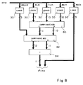
- FIG. 8 represents a particularly advantageous embodiment of a square elevating circuit according to the invention resulting from the optimization of the table of FIG. 7B.
- the terms of rows 0 to 4 of the first row of the table of FIG. 7B are supplied directly as bits of rows 0 to 4 of the square X2 to be supplied.
- a backup backup adder is an adder with three inputs and two outputs. The three entries receive three binary numbers to add.
- An elementary cell of such an adder is similar to that of a normal adder, as represented in FIG. 2A, except that the input Ci-1 of the cell receives the bit of rank i of the third number to be added and that the output Ci of the OR gate 12 is not connected to the next cell.
- the outputs If of the exclusive OR gates 10 constitute a first output S of the back-up adder and the outputs Ci of the OR gates 12 constitute the second output C of this adder.
- the ranks of outputs C are increased by 1.
- Such an adder has the advantage of not present stabilization delay due to the spread of the reservoirs. Its response time is approximately equal to the switching time of the exclusive OR gate 10.
- a first of these carry-save adders, 80 receives the bits of ranks 5 to 14 of the words L1 to L3.
- the three bits of ranks 12 to 14 of the word L3 being zero, the corresponding elementary cells of the adder 80, which must then only summon two bits each, are of the simple type of FIG. 2B.
- a second carry-back adder 82 receives the two outputs of the adder 80 and the bits of ranks 5 to 9 of the word L4. As the bits of rows 10 to 14 of the word L4 are zero, the corresponding cells of the adder 82 are of the simple type of FIG. 2B.
- a normal adder (without carryover backup) 84 sums the outputs of the adder 82 and provides the bits of ranks 5 to 15 of the square X2.
- the adder 80 is a 10-bit adder. Its output S is supplied on 10 bits and its output C on 11. Thus, the adder 82 is an adder of 11 bits and provides an output S on 11 bits and an output C on 12 bits.
- the adder 84 is therefore a 12-bit adder and normally provides a 13-bit output. Only 11 of these 13 bits are used, the others being zero. It turns out in fact, in the example of FIG. 7B, that the last three bits of the output C of the adder 82 are always zero; this makes it possible to simplify the adders 82 and 84 by using half-addition cells in the adder 84 for these bits at 0 and to delete the gates 12 and 14 of the corresponding cells of the adder 82.
- FIG. 9B represents an optimization of the table of FIG. 9A according to what has been described in relation to FIG. 5C.
- terms in the lines have been canceled in order to be able to go up lines 5 and 6 of FIG. 9A.
- the new values of the terms, coming from sums of terms of the same columns and propagations of deductions, are written in the boxes.
- the sum S1 at line L4, column 9, is expressed by x3x4 XOU x0x8.
- the deduction C1 of this sum, in line L3, column 10 is expressed by x3x4 OR (x0x8) *.
- the sum S2 in line L2, column 10, is expressed by x4 * x5 XOU x6x3 and the deduction C2 of this sum, in line L3, column 11, is expressed by x4 * x5x6x3.
- FIG. 10 represents an embodiment of a square elevator circuit according to the invention resulting from the optimization of FIG. 9B.
- This circuit is similar to that of FIG. 8 except that the adder 80 is supplied with an additional bit, of rank 12, of the word L3, and to the adder 82, six additional bits, of ranks 10 to 15 of the word L4.
- the preprocessing circuits 30 of this circuit are distinct from those of FIG. 8 since the logic functions which they must provide, indicated in the table of FIG. 9B, are distinct.
Landscapes
- Physics & Mathematics (AREA)
- General Physics & Mathematics (AREA)
- Engineering & Computer Science (AREA)
- Computational Mathematics (AREA)
- Mathematical Analysis (AREA)
- Pure & Applied Mathematics (AREA)
- Theoretical Computer Science (AREA)
- Computing Systems (AREA)
- Mathematical Optimization (AREA)
- General Engineering & Computer Science (AREA)
- Complex Calculations (AREA)
Abstract
Description
La présente invention concerne un circuit permettant d'élever au carré un nombre binaire X de n bits, noté ci-après [xn-1,xn-2, ... x₀].The present invention relates to a circuit making it possible to square a binary number X of n bits, noted below [x n-1 , x n-2 , ... x₀].
Pour élever un nombre binaire au carré, il est courant d'utiliser une table de carrés stockée dans une mémoire morte (ROM), le nombre X étant appliqué sur les lignes d'adresses de la mémoire ROM. Pour stocker tous les carrés d'un nombre X de n bits, la taille de la mémoire ROM doit être de 2n mots de 2n bits. La surface occupée par une telle table en mémoire ROM est importante.To square a binary number, it is common to use a table of squares stored in a read only memory (ROM), the number X being applied to the address lines of the ROM memory. To store all the squares of a number X of n bits, the size of the ROM memory must be 2 n words of 2n bits. The surface occupied by such a table in ROM memory is significant.
En outre, une mémoire ROM présente un temps d'accès élevé. Dans les technologies courantes actuelles, il n'est pas possible d'accéder à des mots successifs d'une mémoire ROM à une fréquence aussi élevée que de l'ordre de 50 MHz.In addition, a ROM memory has a high access time. In current current technologies, it is not possible to access successive words from a ROM memory at a frequency as high as on the order of 50 MHz.
Une autre méthode pour élever le nombre X au carré consiste à utiliser un multiplieur binaire auquel on fournit deux fois le nombre X.Another method of squaring the number X is to use a binary multiplier to which the number X is supplied twice.
On décrit ci-après le fonctionnement d'un multiplieur binaire classique particulier, dit multiplieur de Booth, qui présente l'avantage d'être rapide et d'occuper une surface relativement faible.The following describes the operation of a particular conventional binary multiplier, known as a Booth multiplier, which has the advantage of being fast and occupying a relatively small area.
En multipliant un nombre binaire X exprimé en décimal par x₀2⁰+x₁2¹+... xi2i+... xn-12n-1 et un nombre binaire Y exprimé en décimal par y₀2⁰+y₁2¹+... yi2i+... yn-12n-1, on obtient un produit XY égal, en décimal, à la somme de tous les produits xiyj2i+j, où xi= 0 ou 1, yj= 0 ou 1, et i et j varient entre 0 et n-1.By multiplying a binary number X expressed in decimal by x₀2⁰ + x₁2¹ + ... x i 2 i + ... x n-1 2 n-1 and a binary number Y expressed in decimal by y₀2⁰ + y₁2¹ +
Les produits xiyj (égaux à 0 ou 1) sont rangés dans un tableau de 2n-1 colonnes numérotées de 0 à 2n-2 de droite à gauche et correspondant à des bits de poids successifs du produit binaire XY, et de n lignes numérotées L1 à Ln.The products x i y j (equal to 0 or 1) are arranged in a table of 2n-1 columns numbered from 0 to 2n-2 from right to left and corresponding to bits of successive weight of the binary product XY, and of n lines numbered L1 to Ln.
La figure 1 représente un tel tableau avec un exemple de nombres X et Y de quatre bits. Dans une colonne de rang k, on range successivement tous les produits xiyj tels que i+j= k. On obtient, comme cela est représenté, un remplissage triangulaire du tableau. La valeur (0 ou 1) de chaque produit xiyj est obtenue par des circuits de prétraitement qui effectuent un ET logique entre le bit xi du nombre X et le bit yj du nombre Y. Chaque ligne Lp (p=1, 2... n) correspond à un mot Lp dont les bits de rangs successifs sont constitués respectivement par les contenus des cases de la ligne Lp. Le produit binaire XY recherché est obtenu en effectuant la somme des mots L1 à Ln.Figure 1 shows such a table with an example of four-bit X and Y numbers. In a column of rank k, we successively rank all the products x i y j such that i + j = k. We obtain, as shown, a triangular filling of the table. The value (0 or 1) of each product x i y j is obtained by preprocessing circuits which perform a logical AND between the bit x i of the number X and the bit y j of the number Y. Each line Lp (p = 1 , 2 ... n) corresponds to a word Lp whose bits of successive ranks respectively consist of the contents of the boxes of the line Lp. The binary product XY sought is obtained by performing the sum of the words L1 to Ln.
Ci après, on utilise indifféremment les termes "ligne" du tableau et "mot", ainsi que "case", "terme", et "bit" de tableau.Hereinafter, the terms "line" of the table and "word" are used interchangeably, as well as "case", "term", and "bit" of table.
Pour effectuer la somme des mots L1 à Ln, il est courant d'utiliser une première série d'additionneurs pour sommer les mots par couples, une deuxième série d'additionneurs pour sommer, par couples, les sorties des additionneurs de la première série... Dans l'exemple de la figure 1, un premier additionneur formerait la somme des mots L1 et L2, un deuxième la somme des mots L3 et L4, et un troisième la somme des résultats fournis par les premier et deuxième additionneurs. Dans le cas général, il faut n-1 additionneurs pour sommer les n mots L.To sum the words L1 to Ln, it is common to use a first series of adders to sum the words in pairs, a second series of adders to sum, in pairs, the outputs of the adders of the first series. .. In the example of FIG. 1, a first adder would form the sum of the words L1 and L2, a second the sum of the words L3 and L4, and a third the sum of the results provided by the first and second adders. In the general case, n-1 adders are needed to sum the n words L.
Lorsque l'on utilise un multiplieur de Booth pour élever au carré un nombre X, on obtient un tableau du type de la figure 1 en remplaçant les y par des x.When we use a Booth multiplier to squared a number X, we obtain a table of the type of figure 1 by replacing the y by x.
La figure 2A représente une cellule d'addition élémentaire d'un additionneur classique. Deux bits de rang i, Ai, Bi, de deux mots à additionner sont fournis à une porte OU Exclusif 10 dont la sortie fournit la somme Si des bits Ai et Bi. En outre, la porte 10 reçoit une retenue Ci-1 provenant de la cellule précédente effectuant la somme des bits de rang i-1 des deux mots à additionner. La cellule fournit une retenue Ci à la cellule suivante par l'intermédiaire d'une porte OU 12 recevant les sorties de trois portes ET 14. Une première des portes 14 reçoit les bits Ai et Bi, une deuxième les bits Ai et Ci-1, et la troisième les bits Bi et Ci-1.FIG. 2A represents an elementary addition cell of a conventional adder. Two bits of rank i, Ai, Bi, of two words to be added are supplied to an Exclusive OR
Un additionneur de p bits oomprend p-1 cellules du type de la figure 2A, appelées cellules complètes d'addition, et, pour le rang 0, une cellule plus simple, appelée cellule de demi-addition, décrite ultérieurement.A p bit adder comprises p-1 cells of the type of FIG. 2A, called complete addition cells, and, for
L'ensemble des portes 12 et 14 présente un certain temps de commutation. Ainsi, une retenue Ci se stabilise avec un certain retard par rapport au moment où les entrées Ai, Bi et Ci-1 sont stables. Il en est de même pour la retenue Ci-1 qui prend une valeur stable avec un certain retard par rapport au moment où les entrées de la cellule précédente sont stables... On dit que la retenue se propage de la cellule de rang 0 jusqu'à la cellule de rang le plus élevé. Le temps de stabilisation de la sortie d'un additionneur de p bits est sensiblement égal au temps de propagation, proportionnel à p.All of the
Si, de plus, la sortie d'un premier additionneur est fournie à un deuxième additionneur, la sortie du deuxième additionneur ne peut se stabiliser que si la sortie du premier additionneur est stable ; le temps de stabilisation du dernier additionneur d'un ensemble d'additionneurs disposés en "cascade" croît avec le nombre d'additionneurs.If, in addition, the output of a first adder is supplied to a second adder, the output of the second adder can only stabilize if the output of the first adder is stable; the stabilization time of the last adder of a set of adders arranged in a "cascade" increases with the number of adders.
En conséquence, pour augmenter la rapidité d'un circuit, tel qu'un multiplieur de Booth, utilisant des additionneurs disposés en cascade, on a intérêt à diminuer la taille des additionneurs et le nombre d'additionneurs disposés en cascade.Consequently, to increase the speed of a circuit, such as a Booth multiplier, using adders arranged in cascade, it is advantageous to reduce the size of the adders and the number of adders arranged in cascade.
Le tableau de la figure 1 présente certaines caractéristiques qui permettent de simplifier les additionneurs à utiliser et de diminuer leur temps de stabilisation. En effet, un grand nombre de cases du tableau sont vides (à 0). Pour sommer les mots L3 et L4, par exemple, il faut normalement un additionneur de 5 bits. Toutefois, les bits de rang 0 et 1 du mot L3 sont nuls et les bits de rang 0 à 2 et 4 du mot L4 sont nuls. Dans un additionneur qui somme les mots L3 et L4, les sorties S0 et S1 sont forcées à 0 et la sortie S2 est directement reliée au bit de rang 2 (x₂y₀) du mot L3. Pour sommer les bits de rang 3, on utilise une cellule de demi-addition et, finalement, pour sommer les bits de rang 4, puisque l'un de ces bits est nul, on utilise une cellule similaire à une cellule de demi-addition. Ainsi, au lieu d'utiliser un additionneur de 5 bits, on utilise un additionneur comprenant seulement deux cellules de demi-addition.The table in FIG. 1 presents certain characteristics which make it possible to simplify the adders to use and to reduce their stabilization time. Indeed, a large number of boxes in the table are empty (at 0). To sum the words L3 and L4, for example, you normally need a 5-bit adder. However, the bits of
La figure 2B représente une cellule de demi-addition. Quand l'un des bits des nombres à additionner est nul, ou bien si la cellule d'addition est la première (elle ne reçoit pas de retenue), la structure de la cellule est plus simple. Dans le cas où l'un des bits, par exemple Bi, est nul, la cellule comprend une porte OU exclusif 16 recevant le bit non-nul Ai et la retenue Ci-1 fournie par la cellule précédente. Une porte ET 18 recevant les bits Ai et Ci-1 fournit la retenue Ci à la cellule suivante. La première cellule d'un additionneur a une structure identique sauf que i=0 et le bit B0 est fourni à la porte 16 à la place de la retenue Ci-1. La structure de la figure 2B est plus simple et plus rapide que celle de la figure 2A. On a donc intérêt à l'adopter chaque fois que possible.Figure 2B shows a half-addition cell. When one of the bits of the numbers to be added is zero, or if the addition cell is the first (it does not receive a carry), the structure of the cell is simpler. In the case where one of the bits, for example Bi, is zero, the cell comprises an exclusive OR
Un objet de la présente invention est de prévoir un circuit élévateur au carré basé sur la méthode de Booth, qui soit particulièrement rapide.An object of the present invention is to provide a squared elevator circuit based on the Booth method, which is particularly rapid.
Un autre objet de la présente invention est de prévoir un tel circuit élévateur au carré qui occupe une surface particulièrement faible.Another object of the present invention is to provide such a square lifting circuit which occupies a particularly small area.
Ces objets sont atteints grâce à un circuit élévateur au carré d'un nombre binaire X de n bits x₀ à xn-1, comprenant des circuits de prétraitement pour former l'ensemble des produits xixj des bits du nombre X, où i et j varient entre 0 et n-1 tel que i≦j. Les sorties des circuits de prétraitement fournissent des mots tels que chacun est formé par une succession aussi complète que possible de produits choisis parmi ceux qui restent dudit ensemble après la formation du mot précédent, chaque produit xixj de cette succession étant classé à un rang i+j+1 du mot si i est différent de j ou à un rang 2i si i=j. Des additionneurs sont connectés pour former la somme des mots en tant que carré du nombre X.These objects are achieved by means of a circuit raising a square of a binary number X of n bits x₀ to x n-1 , comprising preprocessing circuits to form the set of products x i x j of bits of the number X, where i and j vary between 0 and n-1 such that i ≦ j. The outputs of the preprocessing circuits provide words such that each is formed by a succession as complete as possible of products chosen from those which remain of said set after the formation of the preceding word, each product x i x j of this succession being classified at a rank i + j + 1 of the word if i is different from j or rank 2i if i = j. Adders are connected to form the sum of the words as a square of the number X.
Selon un mode de réalisation de la présente invention, les circuits de prétraitement comprennent des moyens pour former la somme des produits correspondant normalement à deux bits de même rang de deux mots, cette somme étant fournie sur l'un desdits deux bits, et l'autre desdits deux bits étant forcé à 0, la retenue de la somme étant propagée vers un bit normalement nul de l'un des mots.According to an embodiment of the present invention, the preprocessing circuits comprise means for forming the sum of the products normally corresponding to two bits of the same rank of two words, this sum being supplied on one of said two bits, and the other of said two bits being forced to 0, the retention of the sum being propagated towards a normally zero bit of one of the words.
Selon un mode de réalisation de la présente invention, les circuits de prétraitement forment directement à partir des bits du nombre X les valeurs des bits à modifier par ladite somme et la propagation de ladite retenue.According to an embodiment of the present invention, the preprocessing circuits form directly from the bits of the number X the values of the bits to be modified by said sum and the propagation of said carry.
Selon un mode de réalisation de la présente invention, les additionneurs comprennent des additionneurs à sauvegarde de retenue disposés en cascade.According to an embodiment of the present invention, the adders include back-up backup adders arranged in cascade.
Selon un mode de réalisation de la présente invention, le circuit élève au carré un nombre signé X' de n+1 bits x₀ à xn. Pour cela, les circuits de prétraitement ajoutent audit ensemble pour former lesdits mots, les termes : 1 classé au rang n+1 d'un mot, xn classé au rang 2n d'un mot, et les inverses des produits xixn, où i varie de 0 à n-1, classés respectivement aux rangs i+n+1 d'un mot.According to an embodiment of the present invention, the circuit squares a signed number X 'of n + 1 bits x₀ to x n . For this, the preprocessing circuits add to said set to form said words, the terms: 1 classified at rank n + 1 of a word, x n classified at rank 2n of a word, and the inverses of the products x i x n , where i varies from 0 to n-1, classified respectively in rows i + n + 1 of a word.
Ces objets, caractéristiques et avantages ainsi que d'autres de la présente invention seront exposés en détail dans la description suivante de modes de réalisation faite à titre non limitatif à l'aide des figures jointes parmi lesquelles :
- la figure 1, précédemment décrite, est destinée à illustrer une méthode classique de multiplication de deux nombres binaires ;
- les figures 2A et 2B, précédemment décrites, représentent des cellules élémentaires d'un additionneur ;
- les figures 3A à 3D illustrent, à l'aide d'un exemple, des étapes d'optimisation d'un circuit élévateur au carré de nombres positifs selon l'invention ;
- les figures 4A et 4B représentent deux modes de réalisation de circuit élévateur au carré selon l'invention, réalisés à partir des tableaux des figures 3B et 3D ;
- les figures 5A à 5C illustrent, à l'aide d'un exemple, des étapes d'optimisation d'un circuit élévateur au carré de nombres signés selon l'invention ;
- la figure 6 représente un mode de réalisation d'un circuit élévateur au carré réalisé à partir du tableau de la figure 5C ;
- les figures 7A et 7B illustrent, à l'aide d'un autre exemple, une étape initiale et une étape finale d'une optimisation de circuit élévateur au carré de nombres positifs selon l'invention ;
- la figure 8 représente un mode de réalisation avantageux de circuit élévateur au carré réalisé à partir du tableau de la figure 7B ;
- les figures 9A et 9B illustrent, à l'aide d'un autre exemple, une étape initiale et une étape finale d'une optimisation de circuit élévateur au carré de nombres signés selon l'invention ; et
- la figure 10 représente un mode de réalisation avantageux de circuit élévateur au carré réalisé à partir du tableau de la figure 9B.
- Figure 1, previously described, is intended to illustrate a conventional method of multiplying two binary numbers;
- FIGS. 2A and 2B, previously described, represent elementary cells of an adder;
- FIGS. 3A to 3D illustrate, using an example, steps for optimizing an elevator circuit squared of positive numbers according to the invention;
- FIGS. 4A and 4B represent two embodiments of a square elevator circuit according to the invention, produced from the tables of FIGS. 3B and 3D;
- FIGS. 5A to 5C illustrate, using an example, steps for optimizing an elevator circuit squared of numbers signed according to the invention;
- FIG. 6 represents an embodiment of a square lifting circuit produced from the table in FIG. 5C;
- FIGS. 7A and 7B illustrate, using another example, an initial step and a final step of an optimization of the booster circuit squared of positive numbers according to the invention;
- FIG. 8 represents an advantageous embodiment of a square elevator circuit produced from the table in FIG. 7B;
- FIGS. 9A and 9B illustrate, with the aid of another example, an initial step and a final step of an optimization of step-up circuit squared of numbers signed according to the invention; and
- FIG. 10 represents an advantageous embodiment of a square elevator circuit produced from the table in FIG. 9B.
La méthode de Booth et les circuits qui en découlent n'ont pas, à la connaissance de la demanderesse, été specifiquement adaptés à la réalisation d'opérations d'élévation au carré. La présente invention propose une telle adaptation dont on verra qu'elle conduit à la réalisation de circuits particulièrement simples et rapides.To the knowledge of the Applicant, the Booth method and the circuits which result therefrom have not been specifically adapted to carrying out squaring operations. The present invention proposes such an adaptation which we will see that it leads to the realization of particularly simple and fast circuits.
La figure 3A reprend le tableau de la figure 1 dans le cas de l'élévation au carré d'un nombre X, tous les couples de produits égaux étant regroupés. Dans chaque colonne, chaque couple de produits xixj, xjxi est remplacé par le produit 2xixj. Les produits xixi (0 par 0 ou 1 par 1) sont égaux à xi, comme cela apparaît dans les tableaux. La multiplication par 2 d'un produit xixj revient à décaler ce produit d'une colonne vers la gauche.FIG. 3A takes up the table of FIG. 1 in the case of the square elevation of a number X, all the pairs of equal products being grouped together. In each column, each pair of products x i x j , x j x i is replaced by the
La figure 3B représente le résultat de ces décalages à gauche. On obtient un tableau de n/2 + 1 lignes (3 dans l'exemple) si n est pair, et (n+1)/2 lignes si n est impair. Chaque produit xixj, tel que i<j (ou bien j<i), est rangé dans la colonne de rang i+j+1 et chaque terme xk (correspondant à un produit xkxk) est rangé dans la colonne de rang 2k.FIG. 3B represents the result of these shifts to the left. We obtain an array of n / 2 + 1 lines (3 in the example) if n is even, and (n + 1) / 2 lines if n is odd. Each product x i x j , such that i <j (or else j <i), is stored in the row column i + j + 1 and each term x k (corresponding to a product x k x k ) is stored in the column of row 2k.
La somme des mots L correspondant aux lignes du tableau constitue le carré X² recherché.The sum of the words L corresponding to the lines of the table constitutes the square X² sought.
Ainsi, la présente invention propose, dans un premier temps, de réarranger les mots à additionner de façon à obtenir n/2 +1 mots, si n est pair, ou (n+1)/2 mots, si n est impair, au lieu des n mots obtenus en appliquant directement la méthode de Booth. On notera de plus que les mots à additionner comprennent un grand nombre de bits à 0 (correspondant à des cases vides ou à 0). Ainsi, outre le fait que l'on réduit le nombre d'additionneurs, on peut utiliser des additionneurs comprenant un plus petit nombre de cellules complètes d'addition. Chaque additionneur sera donc plus rapide et moins encombrant.Thus, the present invention proposes, firstly, to rearrange the words to be added so as to obtain n / 2 +1 words, if n is even, or (n + 1) / 2 words, if n is odd, at locus of the n words obtained by directly applying the Booth method. It should also be noted that the words to be added include a large number of bits at 0 (corresponding to empty boxes or to 0). Thus, in addition to the fact that the number of adders is reduced, adders comprising a smaller number of complete addition cells can be used. Each adder will therefore be faster and less bulky.
Un autre aspect de la présente invention consiste à effectuer des opérations d'optimisation pour annuler des cases supplémentaires du tableau, de manière à annuler des cases extrêmes des lignes, ou même des lignes complètes.Another aspect of the present invention consists in carrying out optimization operations to cancel additional boxes of the table, so as to cancel extreme boxes of the rows, or even of complete rows.
La figure 3C illustre une étape d'optimisation du tableau de la figure 3B selon cet aspect. On a représenté dans le tableau 3B précédent, par un cadre en pointillés, les éléments que l'on modifie pour effectuer cette optimisation. Pour obtenir le tableau de la figure 3C, le terme (x₁x₂) de la ligne L2, colonne 4, est remplacé par la somme de ce terme et de celui (x₂) de la ligne L3, colonne 4, ce qui fournit le terme x₁*x₂ à la ligne L2, colonne 4. Le symbole * indique que le nombre qui le précède est transformé en son inverse logique. Bien entendu, la somme des termes x₁x₂ et x₂ génère une retenue x₁x₂. Cette retenue est reportée dans une case vide à la ligne L2, colonne 5.FIG. 3C illustrates a step of optimizing the table of FIG. 3B according to this aspect. The preceding table 3B shows, by a dotted frame, the elements which are modified to carry out this optimization. To obtain the table in FIG. 3C, the term (x₁x₂) of line L2,
Selon encore un autre aspect de l'invention, une somme (par exemple x₁*x₂ dans la colonne 4) et une retenue (par exemple x₁x₂ dans la colonne 5) ne sont pas obtenues par une cellule d'additionneur qui somme les valeurs des cases correspondantes (x₁x₂ et x₂), mais directement à partir des bits (x₁ et x₂) du nombre X par des portes logiques. Ceci permet de diminuer le nombre de portes logiques reliées en série et donc d'augmenter la vitesse de réponse du circuit.According to yet another aspect of the invention, a sum (for example x₁ * x₂ in column 4) and a carry (for example x₁x₂ in column 5) are not obtained by an adder cell which sums the values of corresponding boxes (x₁x₂ and x₂), but directly from the bits (x₁ and x₂) of the number X by logic gates. This makes it possible to reduce the number of logic gates connected in series and therefore to increase the response speed of the circuit.
L'étape de la figure 3C permet de supprimer une ligne du tableau. Pour obtenir le carré X², il suffit de sommer les deux mots correspondant aux deux lignes du tableau. On économise l'emploi d'un additionneur par rapport à un circuit réalisé à partir du tableau de la figure 3B.The step in FIG. 3C makes it possible to delete a row from the table. To obtain the square X², simply add the two words corresponding to the two lines of the table. The use of an adder is saved compared to a circuit produced from the table in FIG. 3B.
La figure 3D représente une étape d'optimisation du tableau de la figure 3C. Les éléments modifiés dans le tableau de la figure 3C sont encadrés par des pointillés. Le terme (x₀x₁) en ligne L1, colonne 2, est remplacé par la somme de celui-ci et du terme (x₁) en ligne L2, colonne 2. On obtient, en ligne L1, colonne 2, le terme x₀*x₁, et la retenue, x₀x₁, est reportée en ligne L2, colonne 3 où elle remplit une case vide. Comme précédemment, ces somme et retenue sont obtenues directement à partir des bits x₀ et x₁ du nombre X.FIG. 3D represents a step for optimizing the table in FIG. 3C. The elements modified in the table in FIG. 3C are surrounded by dotted lines. The term (x₀x₁) in line L1,
Cette optimisation permet de faire apparaître une case vide (un 0) supplémentaire à l'extrémité droite de la ligne L2 (du mot L2). Ainsi, pour sommer les mots L1 et L2, il faut un additionneur de 4 bits seulement au lieu de 5 dans le cas de la figure 3C. Les bits de rangs 3 à 6 des mots L1 et L2 sont fournis à l'additionneur et les bits de rangs 0 à 2 du mot L1 constituent directement les bits de rangs 0 à 2 du nombre X². Cette optimisation permet donc de diminuer la taille de l'additionneur, et par conséquent la taille et le temps de réponse du circuit.This optimization allows an additional empty box (a 0) to appear at the right end of line L2 (from the word L2). Thus, to sum the words L1 and L2, an adder of only 4 bits is required instead of 5 in the case of FIG. 3C. The bits of
La figure 4A représente un circuit élévateur au carré réalisé à partir du tableau de la figure 3B. Ce circuit comprend des circuits de prétraitement 30 recevant les bits du nombre X à élever au carré. Ces circuits de prétraitement fournissent tous les termes non-nuls (xixj, xk) du tableau de la figure 3B ; ils sont obtenus directement à partir des bits x du nombre X par des portes ET. Un additionneur 5 bits 32 somme les bits de rangs 2 à 6 de mots L1 et L2. Les bits de rangs 0 et 1 du mot L1 sont fournis directement en tant que bits de rangs 0 et 1 du carré X². Un additionneur 4 bits 34 somme le mot L3 aux 4 bits de poids fort de sortie de l'additionneur 32, les deux sorties de poids faible étant fournies directement en tant que bits de rangs 2 et 3 du carré X². Tous les bits sauf un du mot L3 étant nuls, l'additionneur 34 ne comprend que des cellules de demi-addition.FIG. 4A represents a square lifting circuit produced from the table in FIG. 3B. This circuit includes
La figure 4B représente un mode de réalisation de circuit élévateur au carré selon l'invention issu de l'étape d'optimisation de la figure 3D. Ce circuit comprend aussi des circuits de prétraitement 30 recevant les bits du nombre X et fournissant tous les termes non-nuls du tableau de la figure 3D. Ces termes sont obtenus directement à partir de bits x du nombre X par des combinaisons adéquates de portes logiques que l'homme du métier saura trouver par une simple consultation du tableau (par exemple, le terme x₀*x₁ est obtenu par une porte ET recevant le bit x₁ et l'inverse du bit x₀). Les bits de rangs 0 à 2 du mot L1 sont fournis en tant que bits de rangs 0 à 2 du nombre X², et les bits de rangs 3 à 6 des mots L1 et L2 sont sommés par l'additionneur 36 pour fournir les 5 bits restants de rangs 3 à 7 du nombre X². Avec ce mode de réalisation, on économise un additionneur par rapport à celui de la figure 4A.FIG. 4B represents an embodiment of a square elevator circuit according to the invention resulting from the optimization step of FIG. 3D. This circuit also includes
Jusqu'ici, on a supposé que le nombre X était positif. Toutefois, la présente invention s'applique également à des nombres binaires signés X' de n+1 bits [xn,xn-1, ... x₀], dont le bit xn est un bit de signe. Un nombre signé X' est exprimé, en décimal, par la somme des produits xi2i (i variant de 0 à n-1) et du terme -xn2n. Lorsque l'on élève ce nombre au carré, on obtient, en décimal, la somme des termes suivants :
- X², carré en décimal du nombre binaire positif X= [xn-1,xn-2, ... x₀] ;
- la somme des termes -xixn2i+n+1, où i varie de 0 à n-1 ; et
le terme x n22n.
- X², square in decimal of the positive binary number X = [x n-1 , x n-2 , ... x₀];
- the sum of the terms -x i x n 2 i + n + 1 , where i varies from 0 to n-1; and
- the term x n 2 2n .
Si l'on applique la règle classique du "complément à 2" pour exprimer des nombres binaires signés, où l'opposé d'un nombre binaire est égal à son inverse plus 1, le carré X'² s'exprime, en décimal, par la somme des termes X², xn22n, 2n+1, et des produits (xixn)*2i+n+1, où i varie de 0 à n-1.If we apply the classic rule of "complement to 2" to express signed binary numbers, where the opposite of a binary number is equal to its
La figure 5A représente un tableau regroupant ces termes, à l'aide d'un exemple où le nombre signé X' est de 5 bits (4 bits et 1 bit de signe). Les termes du nombre X² sont disposés de la même manière que dans le tableau de la figure 3B dans les colonnes 0 à 6. En outre, dans deux lignes supplémentaires (L4 et L5), on trouve les termes (xixn)*, où i varie de 0 à n-1, classés dans les colonnes respectives i+n+1. On trouve dans la colonne n+1 (5), le terme 1, et dans la colonne 2n (8), le terme xn (x₄). Comme précédemment, il faut sommer les lignes du tableau pour obtenir le carré X'² recherché. L'organisation de la figure 5A n'est pas optimale mais est déjà plus avantageuse qu'une organisation que l'on obtiendrait en appliquant la méthode de Booth.FIG. 5A represents a table grouping together these terms, using an example where the signed number X ′ is 5 bits (4 bits and 1 sign bit). The terms of the number X² are arranged in the same way as in the table in FIG. 3B in
La figure 5B représente une étape d'optimisation du tableau de la figure 5A. Les termes correspondant au nombre X² sont optimisés selon ce qui a été décrit en relation avec la figure 3D. Le terme x₄ de la colonne 8 est reporté à la première ligne de la colonne 8. On obtient ainsi n/2 +2 lignes à additionner (si n est pair) alors qu'avec la méthode de Booth il fallait additionner au moins n+1 lignes.FIG. 5B represents a step for optimizing the table in FIG. 5A. The terms corresponding to the number X² are optimized according to what has been described in relation to FIG. 3D. The term x₄ in
La figure 5C représente un tableau qui illustre une étape d'optimisation supplémentaire selon l'invention. Dans le tableau de la figure 5B, on a entouré par des pointillés les termes affectés par cette optimisation. Le terme (x₁x₂) de la ligne L2, colonne 5, est remplacé par la somme des termes de la colonne 5, lignes L2 à L4 (x₁x₂, (x₀x₄)*, 1). Cette somme est notée S1 dans le tableau de la figure 5C et s'exprime par :![]()
où XOU désigne l'opérateur logique OU Exclusif. La retenue de cette somme est reportée dans la colonne 6. Cette retenue est sommée aux termes (x₂x₃, x₃) des lignes L1 et L2, colonne 6 pour former une somme S2 remplaçant le terme (x₂x₃) de la ligne L1, colonne 6. Cette somme S2 s'exprime par :![]()
La retenue C2 de cette somme S2 est insérée à la case vide de la ligne L1, colonne 7. La retenue C2 s'exprime par :![]()
On dira que la retenue de la somme des termes de la colonne 5 a été propagée vers une case vide d'une colonne (7) de rang supérieur.FIG. 5C represents a table which illustrates an additional optimization step according to the invention. In the table of FIG. 5B, the terms affected by this optimization have been surrounded by dotted lines. The term (x₁x₂) of line L2, ![]()
where XOU designates the logical operator OR Exclusive. The withholding of this sum is reported in ![]()
The C2 deduction of this sum S2 is inserted in the empty box of line L1, ![]()
It will be said that the retention of the sum of the terms of
Ainsi, on libère les cases de rangs 6 à 8 de la ligne L2, qui reçoivent respectivement les termes restants (x₁x₄)*, (x₂x₄)*, et (x₃x₄)* de la ligne L3. On arrive à réduire le tableau de deux lignes.Thus, the boxes of
La figure 6 représente un mode de réalisation de circuit élévateur au carré selon l'invention issu de l'optimisation de la figure 5C. Ce circuit se distingue de celui de la figure 4B par le fait que les circuits de prétraitement 30 fournissent les valeurs du tableau de la figure 5C et que l'additionneur 36 est un additionneur de 5 bits sommant les termes des colonnes 3 à 7 de la figure 5C. Les termes de la colonne 8 sont ignorés car ils correspondent au bit de signe, qui est toujours nul car un carré est positif. En outre, l'additionneur 36 de 5 bits devrait normalement fournir la somme sur 5 bits et 1 bit de retenue. A la figure 6, le bit de retenue de l'additionneur 36, qui constituerait un neuvième bit du carré X'², est ignoré.FIG. 6 represents an embodiment of a square elevator circuit according to the invention resulting from the optimization of FIG. 5C. This circuit is distinguished from that of FIG. 4B by the fact that the
Un nombre binaire X' de n bits et 1 bit de signe peut prendre des valeurs décimales entre -2n et 2n -1. Dans un grand nombre de cas, par exemple si le nombre X' correspond à la différence de deux nombres binaires positifs de n bits, le nombre X' ne prend des valeurs décimales qu'entre -(2n -1) et 2n -1 ; dans ce cas, le carré du nombre X' s'exprime sur 2n bits. Par contre, si le nombre X' peut prendre la valeur -2n, le carré de ce nombre s'exprime sur 2n+1 bits ; on tient alors compte de la colonne de rang 2n.A binary number X 'of n bits and 1 sign bit can take decimal values between -2 n and 2 n -1. In a large number of cases, for example if the number X 'corresponds to the difference of two positive binary numbers of n bits, the number X' takes decimal values only between - (2 n -1) and 2 n - 1; in this case, the square of the number X 'is expressed on 2n bits. On the other hand, if the number X 'can take the value -2 n , the square of this number is expressed on 2n + 1 bits; we then take into account the column of rank 2n.
Les figures 7A et 7B représentent des tableaux correspondant aux étapes d'optimisation des figures 3A et 3D avec l'exemple d'un nombre X positif de n=8 bits.FIGS. 7A and 7B represent tables corresponding to the optimization steps of FIGS. 3A and 3D with the example of a positive number X of n = 8 bits.
Dans la figure 7A, les termes sont répartis selon la règle générale exposée en relation avec la figure 3B. Le tableau comprend 5 lignes au lieu des 8 lignes obtenues en appliquant la méthode de Booth.In FIG. 7A, the terms are distributed according to the general rule exposed in relation to FIG. 3B. Table includes 5 lines instead of the 8 lines obtained by applying the Booth method.
Dans la figure 7B, le nombre de lignes du tableau a été réduit à 4 selon ce qui a été décrit en relation avec la figure 3C et on a annulé les termes les plus à droite jusqu'à la colonne 4 des lignes 2 et 3 selon ce qui a été décrit en relation avec la figure 3D. Le terme de la ligne L1, colonne 2 (x₀x₁) a été remplacé par la somme de ce terme et de celui (x₁) de la ligne L2, colonne 2. Le terme (x₀x₂) de la ligne L1, colonne 3, est remplacé par la somme de ce terme et de la retenue de la somme effectuée dans la colonne 2. Dans la colonne 3, le signe + entouré correspond à l'opération OU Exclusif. Le terme de la ligne L1, colonne 4 (x₀x₃), est remplacé par la somme des termes des lignes L1 à L3 de la colonne 4 et de la retenue de la somme effectuée dans la colonne 3. Cette somme S0 est exprimée par :![]()
Comme la somme S0 correspond à la somme de quatre termes, on a une double retenue. L'une, x₁x₂, est insérée à la ligne L3, colonne 5, et l'autre, x₀x₂x₃, est insérée à la ligne L4, colonne 5, dans deux cases vides respectives.In FIG. 7B, the number of rows in the table has been reduced to 4 according to what has been described in relation to FIG. 3C and the rightmost terms have been canceled up to ![]()
As the sum S0 corresponds to the sum of four terms, there is a double carryover. One, x₁x₂, is inserted in line L3,
Bien entendu, comme on l'a précédemment mentionné, les sommes insérées dans des cases du tableau ne sont pas obtenues par des additionneurs, mais directement par des circuits logiques, à partir des bits du nombre X. Ainsi, par exemple, le terme x₀x₂x₃ de la ligne L4, colonne 5, est obtenu par une porte ET à trois entrées recevant les bits x₀, x₂ et x₃ respectivement.Of course, as previously mentioned, the sums inserted in boxes of the table are not obtained by adders, but directly by logic circuits, from the bits of the number X. Thus, for example, the term x₀x₂x₃ of line L4,
Dans le tableau de la figure 7B, on a également annulé le terme de la ligne L4, colonne 10, en le sommant au terme de la ligne précédente en reportant la retenue dans la colonne 11, et on a annulé le terme de la ligne L3, colonne 12, en le sommant au terme de la ligne précédente en reportant la retenue à la place du 0 de la ligne L2, colonne 13.In the table of FIG. 7B, the term of line L4,
En faisant apparaître des 0 aux extrémités des lignes, on simplifie la structure des additionneurs qui vont additionner ces lignes. Notamment, en faisant apparaître des 0 à l'extrémité droite des lignes, le nombre de bits des additionneurs diminue. Une optimisation particulièrement bonne est obtenue lorsque l'on a supprimé le plus grand nombre possible de termes aux extrémités gauche et droite des lignes du tableau. Ces suppressions peuvent se faire de nombreuses manières qui apparaîtront à l'homme du métier, les suppressions illustrées dans les tableaux n'en constituent que des exemples. En effet, les termes de chaque colonne peuvent être permutés et chaque permutation peut entraîner une somme de termes différente pour annuler une case du tableau.By showing 0s at the ends of the lines, we simplify the structure of the adders that will add these lines. In particular, by making 0 appear at the right end of the lines, the number of bits of the adders decreases. A particularly good optimization is obtained when we have deleted as many terms as possible at the left and right ends of the rows of the table. These deletions can be done in many ways which will appear to a person skilled in the art, the deletions illustrated in the tables are only examples thereof. Indeed, the terms of each column can be permuted and each permutation can result in a different sum of terms to cancel a box in the table.
La figure 8 représente un mode de réalisation particulièrement avantageux de circuit élévateur au carré selon l'invention issu de l'optimisation du tableau de la figure 7B. Les termes de rangs 0 à 4 de la première ligne du tableau de la figure 7B sont fournis directement en tant que bits de rangs 0 à 4 du carré X² à fournir.FIG. 8 represents a particularly advantageous embodiment of a square elevating circuit according to the invention resulting from the optimization of the table of FIG. 7B. The terms of
Selon un mode de réalisation avantageux de l'invention, on utilise des additionneurs à sauvegarde de retenue (CARRY-SAVE) pour effectuer les sommes. Un additionneur à sauvegarde de retenue est un additionneur présentant trois entrées et deux sorties. Les trois entrées reçoivent trois nombres binaires à additionner. Une cellule élémentaire d'un tel additionneur est similaire à celle d'un additionneur normal, telle que représentée dans la figure 2A, sauf que l'entrée Ci-1 de la cellule reçoit le bit de rang i du troisième nombre à additionner et que la sortie Ci de la porte OU 12 n'est pas reliée à la cellule suivante. Les sorties Si des portes OU exclusif 10 constituent une première sortie S de l'additionneur à sauvegarde de retenue et les sorties Ci des portes OU 12 constituent la deuxième sortie C de cet additionneur. En outre, les rangs des sorties C sont augmentés de 1. Un tel additionneur a l'avantage de ne pas présenter de retard de stabilisation dû à la propagation des retenues. Son temps de réponse est approximativement égal au temps de commutation de la porte OU exclusif 10.According to an advantageous embodiment of the invention, adders with retention backup (CARRY-SAVE) are used to make the sums. A backup backup adder is an adder with three inputs and two outputs. The three entries receive three binary numbers to add. An elementary cell of such an adder is similar to that of a normal adder, as represented in FIG. 2A, except that the input Ci-1 of the cell receives the bit of rank i of the third number to be added and that the output Ci of the
Un premier de ces additionneurs à sauvegarde de retenue, 80, reçoit les bits de rangs 5 à 14 des mots L1 à L3. Les trois bits de rangs 12 à 14 du mot L3 étant nuls, les cellules élémentaires correspondantes de l'additionneur 80, qui ne doivent alors sommer que deux bits chacun, sont du type simple de la figure 2B.A first of these carry-save adders, 80, receives the bits of
Un deuxième additionneur à sauvegarde de retenue 82 reçoit les deux sorties de l'additionneur 80 et les bits de rangs 5 à 9 du mot L4. Comme les bits de rangs 10 à 14 du mot L4 sont nuls, les cellules correspondantes de l'additionneur 82 sont du type simple de la figure 2B.A second carry-
Finalement, un additionneur normal (sans sauvegarde de retenue) 84 somme les sorties de l'additionneur 82 et fournit les bits de rangs 5 à 15 du carré X².Finally, a normal adder (without carryover backup) 84 sums the outputs of the
L'additionneur 80 est un additionneur de 10 bits. Sa sortie S est fournie sur 10 bits et sa sortie C sur 11. Ainsi, l'additionneur 82 est un additionneur de 11 bits et fournit une sortie S sur 11 bits et une sortie C sur 12 bits. L'additionneur 84 est donc un additionneur de 12 bits et fournit normalement une sortie sur 13 bits. Seulement 11 parmi ces 13 bits sont utilisés, les autres étant nuls. Il s'avère en fait, dans l'exemple de la figure 7B, que les trois derniers bits de la sortie C de l'additionneur 82 sont toujours nuls ; ceci permet de simplifier les additionneurs 82 et 84 en utilisant pour ces bits à 0 des cellules de demi-addition dans l'additionneur 84 et de supprimer les portes 12 et 14 des cellules correspondantes de l'additionneur 82.The
La figure 9A représente un tableau, correspondant à celui de la figure 5B, pour un nombre X' de n=8 bits x₀ à x₇ et d'un bit de signe x₈. Ce tableau est rempli selon les règles générales déjà énoncées en relation avec les figures 5A et 5B.FIG. 9A represents a table, corresponding to that of FIG. 5B, for a number X 'of n = 8 bits x₀ to x₇ and of a bit of sign x₈. This table is filled in according to the general rules already set out in relation to FIGS. 5A and 5B.
La figure 9B représente une optimisation du tableau de la figure 9A selon ce qui a été décrit en relation avec la figure 5C. En effectuant des sommes qui ne seront pas décrites en détail, on a annulé des termes dans les lignes afin de pouvoir remonter les lignes 5 et 6 de la figure 9A. Les nouvelles valeurs des termes, provenant de sommes de termes de mêmes colonnes et de propagations de retenues, sont inscrites dans les cases. La somme S1 à la ligne L4, colonne 9, s'exprime par x₃x₄ XOU x₀x₈. La retenue C1 de cette somme, dans la ligne L3, colonne 10, s'exprime par x₃x₄ OU (x₀x₈)*. La somme S2 dans la ligne L2, colonne 10, s'exprime par x₄*x₅ XOU x₆x₃ et la retenue C2 de cette somme, dans la ligne L3, colonne 11, s'exprime par x₄*x₅x₆x₃.FIG. 9B represents an optimization of the table of FIG. 9A according to what has been described in relation to FIG. 5C. By making sums which will not be described in detail, terms in the lines have been canceled in order to be able to go up
La figure 10 représente un mode de réalisation de circuit élévateur au carré selon l'invention issu de l'optimisation de la figure 9B. Ce circuit est similaire à celui de la figure 8 sauf que l'on fournit à l'additionneur 80 un bit supplémentaire, de rang 12, du mot L3, et à l'additionneur 82 six bits supplémentaires, de rangs 10 à 15 du mot L4. Bien entendu, les circuits de prétraitement 30 de ce circuit sont distincts de ceux de la figure 8 puisque les fonctions logiques qu'ils doivent assurer, indiquées dans le tableau de la figure 9B, sont distinctes.FIG. 10 represents an embodiment of a square elevator circuit according to the invention resulting from the optimization of FIG. 9B. This circuit is similar to that of FIG. 8 except that the
La présente invention a été décrite à l'aide d'exemples particuliers de simplifications possibles de tableaux. Bien entendu, de nombreuses autres possibilités restent offertes à l'homme du métier en permutant les termes des colonnes et en annulant des termes à sa discrétion.The present invention has been described using specific examples of possible simplifications of tables. Of course, many other possibilities remain open to the person skilled in the art by permuting the terms of the columns and canceling terms at his discretion.
Claims (5)
1 classé au rang n+1 d'un mot,
xn classé au rang 2n d'un mot, et
les inverses des produits xixn, où i varie de 0 à n-1, classés respectivement aux rangs i+n+1 d'un mot.Square elevator circuit, according to any one of claims 1 to 3, of a signed number X 'of n + 1 bits x₀ to x n , characterized in that the preprocessing circuits include means for adding to said set to form said words, the terms:
1 ranked at rank n + 1 of a word,
x n ranked in rank 2n of a word, and
the inverses of the products x i x n , where i varies from 0 to n-1, classified respectively in rows i + n + 1 of a word.
Applications Claiming Priority (2)
| Application Number | Priority Date | Filing Date | Title |
|---|---|---|---|
| FR9313589A FR2712410B1 (en) | 1993-11-08 | 1993-11-08 | Elevating circuit squared with binary numbers. |
| FR9313589 | 1993-11-08 |
Publications (1)
| Publication Number | Publication Date |
|---|---|
| EP0652507A1 true EP0652507A1 (en) | 1995-05-10 |
Family
ID=9452851
Family Applications (1)
| Application Number | Title | Priority Date | Filing Date |
|---|---|---|---|
| EP94410092A Withdrawn EP0652507A1 (en) | 1993-11-08 | 1994-10-25 | Binary number squaring circuit |
Country Status (4)
| Country | Link |
|---|---|
| US (1) | US5629885A (en) |
| EP (1) | EP0652507A1 (en) |
| JP (1) | JPH07191832A (en) |
| FR (1) | FR2712410B1 (en) |
Cited By (1)
| Publication number | Priority date | Publication date | Assignee | Title |
|---|---|---|---|---|
| EP1006437A1 (en) * | 1998-11-30 | 2000-06-07 | TELEFONAKTIEBOLAGET L M ERICSSON (publ) | Digital value processor for estimating the square of a digital value |
Families Citing this family (16)
| Publication number | Priority date | Publication date | Assignee | Title |
|---|---|---|---|---|
| DE19709106A1 (en) * | 1997-03-06 | 1998-09-10 | Philips Patentverwaltung | Arithmetic circuit for calculating a square |
| US6018758A (en) * | 1997-07-30 | 2000-01-25 | Lucent Technologies Inc. | Squarer with diagonal row merged into folded partial product array |
| US6260056B1 (en) * | 1998-08-21 | 2001-07-10 | Ati International Srl | Circuit and method for fast squaring by breaking the square into a plurality of terms |
| US6393453B1 (en) * | 1998-09-22 | 2002-05-21 | Ati International Srl | Circuit and method for fast squaring |
| US6460065B1 (en) * | 1998-09-22 | 2002-10-01 | Ati International Srl | Circuit and method for partial product bit shifting |
| US6301598B1 (en) * | 1998-12-09 | 2001-10-09 | Lsi Logic Corporation | Method and apparatus for estimating a square of a number |
| US6298368B1 (en) * | 1999-04-23 | 2001-10-02 | Agilent Technologies, Inc. | Method and apparatus for efficient calculation of an approximate square of a fixed-precision number |
| ITTO20010818A1 (en) * | 2001-08-17 | 2003-02-17 | Telecom Italia Lab Spa | CIRCUIT FOR ELEVATING TO POWER. |
| US7003544B1 (en) * | 2001-10-16 | 2006-02-21 | Altera Corporation | Method and apparatus for generating a squared value for a signed binary number |
| US11144316B1 (en) | 2018-04-17 | 2021-10-12 | Ali Tasdighi Far | Current-mode mixed-signal SRAM based compute-in-memory for low power machine learning |
| US11016732B1 (en) | 2018-04-17 | 2021-05-25 | Ali Tasdighi Far | Approximate nonlinear digital data conversion for small size multiply-accumulate in artificial intelligence |
| US10884705B1 (en) | 2018-04-17 | 2021-01-05 | Ali Tasdighi Far | Approximate mixed-mode square-accumulate for small area machine learning |
| US11467805B1 (en) | 2020-07-10 | 2022-10-11 | Ali Tasdighi Far | Digital approximate multipliers for machine learning and artificial intelligence applications |
| US11416218B1 (en) | 2020-07-10 | 2022-08-16 | Ali Tasdighi Far | Digital approximate squarer for machine learning |
| US11610104B1 (en) | 2019-12-30 | 2023-03-21 | Ali Tasdighi Far | Asynchronous analog accelerator for fully connected artificial neural networks |
| US11615256B1 (en) | 2019-12-30 | 2023-03-28 | Ali Tasdighi Far | Hybrid accumulation method in multiply-accumulate for machine learning |
Citations (2)
| Publication number | Priority date | Publication date | Assignee | Title |
|---|---|---|---|---|
| US3610906A (en) * | 1968-11-07 | 1971-10-05 | Burroughs Corp | Binary multiplication utilizing squaring techniques |
| EP0224963A1 (en) * | 1985-11-29 | 1987-06-10 | Trt Telecommunications Radioelectriques Et Telephoniques | Device for square summation |
-
1993
- 1993-11-08 FR FR9313589A patent/FR2712410B1/en not_active Expired - Fee Related
-
1994
- 1994-10-25 EP EP94410092A patent/EP0652507A1/en not_active Withdrawn
- 1994-11-07 US US08/335,576 patent/US5629885A/en not_active Expired - Fee Related
- 1994-11-08 JP JP6298031A patent/JPH07191832A/en active Pending
Patent Citations (2)
| Publication number | Priority date | Publication date | Assignee | Title |
|---|---|---|---|---|
| US3610906A (en) * | 1968-11-07 | 1971-10-05 | Burroughs Corp | Binary multiplication utilizing squaring techniques |
| EP0224963A1 (en) * | 1985-11-29 | 1987-06-10 | Trt Telecommunications Radioelectriques Et Telephoniques | Device for square summation |
Non-Patent Citations (1)
| Title |
|---|
| "UNIT TO SQUARE A NUMBER IN REDUCED TIME AND AREA", IBM TECHNICAL DISCLOSURE BULLETIN., vol. 34, no. 7B, December 1991 (1991-12-01), NEW YORK US, pages 339 - 340, XP000282599 * |
Cited By (3)
| Publication number | Priority date | Publication date | Assignee | Title |
|---|---|---|---|---|
| EP1006437A1 (en) * | 1998-11-30 | 2000-06-07 | TELEFONAKTIEBOLAGET L M ERICSSON (publ) | Digital value processor for estimating the square of a digital value |
| WO2000033174A1 (en) * | 1998-11-30 | 2000-06-08 | Telefonaktiebolaget Lm Ericsson (Publ) | Digital value processor |
| US6463452B1 (en) | 1998-11-30 | 2002-10-08 | Telefonaktiebolaget Lm Ericsson | Digital value processor |
Also Published As
| Publication number | Publication date |
|---|---|
| FR2712410B1 (en) | 1996-02-09 |
| US5629885A (en) | 1997-05-13 |
| JPH07191832A (en) | 1995-07-28 |
| FR2712410A1 (en) | 1995-05-19 |
Similar Documents
| Publication | Publication Date | Title |
|---|---|---|
| EP0652507A1 (en) | Binary number squaring circuit | |
| EP0541462B1 (en) | Squaring circuit for binary numbers | |
| EP0204603B1 (en) | Fast calculating of the direct or reverse cosine transform of a discrete signal | |
| EP0971297B1 (en) | Method for global clock circuit routing and placement on an integrated circuit and associated devices | |
| EP0262032B1 (en) | Binary adder having a fixed operand, and a parallel/serial multiplier comprising such an adder | |
| EP0110767B1 (en) | Fast binary multiplier | |
| EP0472447A1 (en) | Cellular balanced delay tree multiplier and it's method of realisation | |
| FR2656124A1 (en) | PROGRAMMABLE SERIES MULTIPLIER. | |
| EP2366246B1 (en) | Integrated circuit array, and in particular a large-sized image sensor | |
| FR2739991A1 (en) | IIR digital filter | |
| EP0309348A1 (en) | Binary addition and multiplication device | |
| EP0476592A2 (en) | Address generator for the data storage of a processor | |
| EP0341097B1 (en) | Recursive adder to calculate the sum of two operands | |
| FR2599526A1 (en) | MOS adder and MOS binary multiplier comprising at least one such adder | |
| EP0046105B1 (en) | Fast digital operator device | |
| EP0152331A2 (en) | Arithmetic logic unit with overflow indicator | |
| EP0310524A1 (en) | Digital-analog converter of weighted sums of binary words | |
| FR2660510A1 (en) | Method and device for programmable interconnection between two electronic circuit assemblies and application to a programmable logic circuit | |
| EP0718755B1 (en) | Electronic component, more particularly capable of performing a radix 4 division of two numbers | |
| EP0128072A1 (en) | Binary multiplier with sign extension for the multiplication of signed and unsigned numbers | |
| FR2783944A1 (en) | Signal distribution circuit and method of connection to a signal line | |
| EP0021908A1 (en) | Charge transfer phase inverter and differential amplifier comprising such a device | |
| EP0572289A1 (en) | Network line sections ordering especially for the calculation of cross-talksbetween lines. | |
| FR2681710A1 (en) | Neural computer | |
| FR2553539A1 (en) | Fast multiplier structure in MOS integrated circuits |
Legal Events
| Date | Code | Title | Description |
|---|---|---|---|
| PUAI | Public reference made under article 153(3) epc to a published international application that has entered the european phase |
Free format text: ORIGINAL CODE: 0009012 |
|
| AK | Designated contracting states |
Kind code of ref document: A1 Designated state(s): DE FR GB IT |
|
| 17P | Request for examination filed |
Effective date: 19951013 |
|
| RAP3 | Party data changed (applicant data changed or rights of an application transferred) |
Owner name: STMICROELECTRONICS S.A. |
|
| 17Q | First examination report despatched |
Effective date: 19990201 |
|
| GRAG | Despatch of communication of intention to grant |
Free format text: ORIGINAL CODE: EPIDOS AGRA |
|
| GRAG | Despatch of communication of intention to grant |
Free format text: ORIGINAL CODE: EPIDOS AGRA |
|
| GRAH | Despatch of communication of intention to grant a patent |
Free format text: ORIGINAL CODE: EPIDOS IGRA |
|
| STAA | Information on the status of an ep patent application or granted ep patent |
Free format text: STATUS: THE APPLICATION IS DEEMED TO BE WITHDRAWN |
|
| 18D | Application deemed to be withdrawn |
Effective date: 20000411 |