EP0651422B1 - Colour display tube having an external magnetic shield - Google Patents
Colour display tube having an external magnetic shield Download PDFInfo
- Publication number
- EP0651422B1 EP0651422B1 EP94203071A EP94203071A EP0651422B1 EP 0651422 B1 EP0651422 B1 EP 0651422B1 EP 94203071 A EP94203071 A EP 94203071A EP 94203071 A EP94203071 A EP 94203071A EP 0651422 B1 EP0651422 B1 EP 0651422B1
- Authority
- EP
- European Patent Office
- Prior art keywords
- display
- display screen
- colour
- display tube
- tube
- Prior art date
- Legal status (The legal status is an assumption and is not a legal conclusion. Google has not performed a legal analysis and makes no representation as to the accuracy of the status listed.)
- Expired - Lifetime
Links
Images

Classifications
-
- H—ELECTRICITY
- H01—ELECTRIC ELEMENTS
- H01J—ELECTRIC DISCHARGE TUBES OR DISCHARGE LAMPS
- H01J29/00—Details of cathode-ray tubes or of electron-beam tubes of the types covered by group H01J31/00
- H01J29/003—Arrangements for eliminating unwanted electromagnetic effects, e.g. demagnetisation arrangements, shielding coils
-
- H—ELECTRICITY
- H04—ELECTRIC COMMUNICATION TECHNIQUE
- H04N—PICTORIAL COMMUNICATION, e.g. TELEVISION
- H04N9/00—Details of colour television systems
- H04N9/12—Picture reproducers
- H04N9/16—Picture reproducers using cathode ray tubes
- H04N9/29—Picture reproducers using cathode ray tubes using demagnetisation or compensation of external magnetic fields
-
- H—ELECTRICITY
- H01—ELECTRIC ELEMENTS
- H01J—ELECTRIC DISCHARGE TUBES OR DISCHARGE LAMPS
- H01J2229/00—Details of cathode ray tubes or electron beam tubes
- H01J2229/0007—Elimination of unwanted or stray electromagnetic effects
- H01J2229/003—Preventing or cancelling fields entering the enclosure
Definitions
- the invention relates to a colour display tube having an envelope and comprising means for generating electrons, a transparent display window, a display screen having a pattern of phosphor elements on the inner surface of the window and means for directing electrons onto the display screen.
- Such a colour display tube may be, for example of the box-shaped type or of the type in which the display window is connected by means of a funnel-shaped envelope portion having a neck portion accommodating the means for generating electrons, a colour selection means arranged opposite the display screen and an internal magnetic shield arranged within the funnel-shaped portion and having two long side walls parallel to the long axis of the display screen (the x-axis), two short side walls parallel to the short axis of the display screen (the y-axis), and a gun-sided open end which extends transversely to the longitudinal axis of the display tube.
- a colour selection means is herein understood to mean, for example, an apertured shadow mask sheet or a wire mask.
- the earth's magnetic field deflects the electron paths, which without any measures may be so large that the electrons impinge upon the wrong phosphor element (mislanding) and produce a discolouration of the picture.
- the component of the earth's magnetic field in the axial direction of the display tube (referred to as the axial field) plays an important role in this respect, which may become manifest as a lack of colour or even as a colour impurity in the corners of the display screen.
- a known measure of reducing mislandings due to the earth's magnetic field is the use of an internal magnetic shield which, together with the similarly ferromagnetic shadow mask, partially shields the earth's magnetic field.
- the shape of such a shield roughly follows the contours of the envelope of the display tube. This means that the funnel-shaped shield has two long, trapezoidal sides which are parallel to the long axis (the x-axis) of the display screen and two short, trapezoidal sides which are parallel to the short axis (the y-axis) of the display screen.
- the short sides of the shield are often provided from the gun-sided aperture (17, Fig. 3) with triangular recesses (18, 19, Fig. 3) so as to reduce mislanding in the corners due to the axial field. If relatively small tubes and a relatively large pitch of the elements of the phosphor pattern on the display screen are used, an acceptable result may be achieved in this way. However, if larger display tubes and/or a smaller pitch of the phosphor elements are used, this type of solution does not always ensure a sufficient colour purity.
- an external shield is sometimes provided, either or not in combination with an internal shield.
- a metal cover is arranged in the tube with a more or less tight fit, see, for example US-A-4,845,402.
- a colour display tube of the type described in the opening paragraph is therefore characterized in that it is positioned within a volume which is defined by an open arrangement (frame) of bars of a soft- magnetic material.
- the cross-sections of the bars and the magnetic permeability of the bar material may be chosen to be such that a given shielding effect is achieved.
- the bars whose ends are interconnected, are arranged, for example in such a way that they constitute the ribs of a block. Then they may be arranged, for example against the walls of the cabinet of a TV set or a monitor.
- they may define a block whose sides are constituted by networks (gratings) of bars.
- a demagnetization coil which can be connected to an energizing circuit may be used.
- the display tube shown in a horizontal cross-section in Fig. 1a comprises a glass envelope consisting of a display window 1, a cone 2 and a neck 3.
- the neck 3 accommodates an electrode system 4 with three electron guns for generating three electron beams 5, 6 and 7.
- the electron beams are generated in one plane (here the plane of the drawing) and are directed onto a display screen 8 arranged internally on the display window 1 and consisting of a large number of red, green and blue luminescing phosphor elements coated with an aluminium backing.
- the electron beams 5, 6 and 7 are deflected across the display screen 8 by means of a deflection coil system 9 arranged coaxially around the tube axis and pass a colour selection electrode 10, here consisting of a metal plate with apertures 11.
- the three electron beams 5, 6 and 7 pass the apertures 11 at a small angle and consequently impinge on phosphor elements of one colour only.
- a funnel-shaped magnetic shield 16 is arranged within the glass envelope.
- mislanding M M ⁇ l 1 .l 2 .eB 2 mv o in which l 1 is the distance between the electron source and the shadow mask and l 2 is the distance between the shadow mask and the screen. It is important to reduce the mislanding as much as possible because this may immediately lead to, for example a greater brightness of the tube. If the tube is larger, l 1 and l 2 both increase, so that the mislanding will become quadratically larger.
- the direction of the disturbing magnetic field in the tube depends on the location and orientation of the apparatus.
- this shield is demagnetized by means of a decreasing alternating field whenever the tube is switched on.
- the shields necessarily have a gun-sided open end. This means that there can be no question of a total shielding.
- the invention is based on the surprising recognition that a considerable decrease of mislandings due to the earth's magnetic field can be achieved by placing the display tube in an open arrangement (frame) 14 (Fig. 1); 15 (Fig. 2) of bars of a soft-magnetic material.
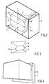
- FIG. 2 shows a definition of a system of axes in a display tube and of locations on the screen.
- the component of the earth's magnetic field in the z-direction is considered, which is the field known as the axial field.
- the Table states computed values of the mislandings of the electrons in the north-east corner (NE) of the display screen for a 66 inch FS tube having an acceleration voltage of 27.5 kV.
- a frame comprising 12 bars having a cross-section of 5 x 5 mm and a magnetic permeability of 1 x 10 6 has been taken as an example.
- a demagnetization coil (not shown) is preferably arranged around the magnetic frame so as to demagnetize the frame when the tube is switched on.
- the bars of the magnetic frame may be arranged efficiently against the inner walls of a cabinet accommodating the display tube, like the cabinet 20 shown in Fig. 4.
- a shielding effect will generally be noticeable if the following condition: is satisfied for a frame having the shape ("block") shown in Fig. 2.
- c is the dimension of the rib of the block parallel to the direction of the magnetic field considered (in accordance with the Table) and a and b are the dimensions of the two ribs perpendicular thereto.
- S denotes the cross-section of the bars.
Landscapes
- Physics & Mathematics (AREA)
- Electromagnetism (AREA)
- Engineering & Computer Science (AREA)
- Multimedia (AREA)
- Signal Processing (AREA)
- Electrodes For Cathode-Ray Tubes (AREA)
- Vessels, Lead-In Wires, Accessory Apparatuses For Cathode-Ray Tubes (AREA)
Description
- The invention relates to a colour display tube having an envelope and comprising means for generating electrons, a transparent display window, a display screen having a pattern of phosphor elements on the inner surface of the window and means for directing electrons onto the display screen.
- Such a colour display tube may be, for example of the box-shaped type or of the type in which the display window is connected by means of a funnel-shaped envelope portion having a neck portion accommodating the means for generating electrons, a colour selection means arranged opposite the display screen and an internal magnetic shield arranged within the funnel-shaped portion and having two long side walls parallel to the long axis of the display screen (the x-axis), two short side walls parallel to the short axis of the display screen (the y-axis), and a gun-sided open end which extends transversely to the longitudinal axis of the display tube.
- A colour selection means is herein understood to mean, for example, an apertured shadow mask sheet or a wire mask.
- In a colour display tube the earth's magnetic field deflects the electron paths, which without any measures may be so large that the electrons impinge upon the wrong phosphor element (mislanding) and produce a discolouration of the picture. Particularly the component of the earth's magnetic field in the axial direction of the display tube (referred to as the axial field) plays an important role in this respect, which may become manifest as a lack of colour or even as a colour impurity in the corners of the display screen.
- A known measure of reducing mislandings due to the earth's magnetic field is the use of an internal magnetic shield which, together with the similarly ferromagnetic shadow mask, partially shields the earth's magnetic field. The shape of such a shield roughly follows the contours of the envelope of the display tube. This means that the funnel-shaped shield has two long, trapezoidal sides which are parallel to the long axis (the x-axis) of the display screen and two short, trapezoidal sides which are parallel to the short axis (the y-axis) of the display screen.
- The short sides of the shield are often provided from the gun-sided aperture (17, Fig. 3) with triangular recesses (18, 19, Fig. 3) so as to reduce mislanding in the corners due to the axial field. If relatively small tubes and a relatively large pitch of the elements of the phosphor pattern on the display screen are used, an acceptable result may be achieved in this way. However, if larger display tubes and/or a smaller pitch of the phosphor elements are used, this type of solution does not always ensure a sufficient colour purity. To further reduce the influence of the earth's magnetic field, an external shield is sometimes provided, either or not in combination with an internal shield. For this purpose, a metal cover is arranged in the tube with a more or less tight fit, see, for example US-A-4,845,402.
- It is an object of the present invention to provide a shielded colour display tube which effectively reduces the detrimental effect of the earth's magnetic field on colour purity without an external cover being necessary.
- According to the invention, a colour display tube of the type described in the opening paragraph is therefore characterized in that it is positioned within a volume which is defined by an open arrangement (frame) of bars of a soft- magnetic material.
- The cross-sections of the bars and the magnetic permeability of the bar material may be chosen to be such that a given shielding effect is achieved.
- In a simple embodiment the bars, whose ends are interconnected, are arranged, for example in such a way that they constitute the ribs of a block. Then they may be arranged, for example against the walls of the cabinet of a TV set or a monitor.
- In a complicated embodiment they may define a block whose sides are constituted by networks (gratings) of bars.
- When the colour display tube is switched on, it is important to demagnetize the arrangement of soft-magnetic bars, preferably by means of an alternating field decreasing in strength with respect to time, so as to make use of the high anhysteresis permeability. For this purpose, a demagnetization coil which can be connected to an energizing circuit may be used.
- The larger the volume which is defined by the arrangement of bars, the more magnetic flux of the colour display tube can be captured.
- These and other aspects of the invention will be apparent from and elucidated with reference to the embodiments described hereinafter.
- In the drawings
- Fig. 1a is a horizontal cross-section of a colour display tube having an external shield;
- Fig. 1b shows diagrammatically the cause of mislanding;
- Fig. 2 is a perspective elevational view of a colour display tube having an external shield, and, indicated therein, a system of axes and the positions on the display screen where beam mislandings are measured;
- Fig. 3 is a perspective elevational view of an embodiment of a prior-art internal shield, and
- Fig. 4 is a perspective elevational view of an embodiment of a display having a shielded colour display tube according to the invention.
- The display tube shown in a horizontal cross-section in Fig. 1a comprises a glass envelope consisting of a
display window 1, acone 2 and aneck 3. Theneck 3 accommodates anelectrode system 4 with three electron guns for generating threeelectron beams display screen 8 arranged internally on thedisplay window 1 and consisting of a large number of red, green and blue luminescing phosphor elements coated with an aluminium backing. On their path to thedisplay screen 8, theelectron beams display screen 8 by means of adeflection coil system 9 arranged coaxially around the tube axis and pass acolour selection electrode 10, here consisting of a metal plate withapertures 11. The threeelectron beams apertures 11 at a small angle and consequently impinge on phosphor elements of one colour only. A funnel-shapedmagnetic shield 16 is arranged within the glass envelope. - In a colour display tube electrons pass through apertures of a shadow mask and impinge upon a phosphor. The position of the phosphors is optimal for one tube orientation in one given earth's magnetic field (earth location). For a different orientation or earth's magnetic field, the electrons impinge upon another spot on the shadow mask. This causes a distortion of the picture which is particularly detrimental in colour monitors. Moreover, the electrons reach the mask at a different angle. If they pass through an aperture, they are incident with a given mislanding M on the screen under the influence of a field transverse to their direction of movement (see Fig. 1b). If this mislanding is too large, the wrong phosphor element may even be reached, thus causing colour errors.
- A computation of the extent of mislanding for the case where the earth's magnetic field is not compensated for at all will be given hereinafter. In a homogeneous field having a size B an electron describes a path having a radius R which is given by R = mvo/eB with m, vo and e denoting mass, velocity and charge, respectively, of the electron. At an earth's magnetic field of 5*10-5T (∼ 1/2 gauss), , an electron velocity vo of 108 m/sec and e/m = 1.76 x 10¹¹ C/kg , this results in R = 11.4 m. A simple geometrical consideration then yields for the mislanding M:

- The direction of the disturbing magnetic field in the tube depends on the location and orientation of the apparatus. To adapt the magnetization of the shield to the field which is present in a given situation, this shield is demagnetized by means of a decreasing alternating field whenever the tube is switched on.
- The shields necessarily have a gun-sided open end. This means that there can be no question of a total shielding.
- The invention is based on the surprising recognition that a considerable decrease of mislandings due to the earth's magnetic field can be achieved by placing the display tube in an open arrangement (frame) 14 (Fig. 1); 15 (Fig. 2) of bars of a soft-magnetic material.
- To simplify the explanation, Fig. 2 shows a definition of a system of axes in a display tube and of locations on the screen. Here, only the component of the earth's magnetic field in the z-direction is considered, which is the field known as the axial field.
- The Table states computed values of the mislandings of the electrons in the north-east corner (NE) of the display screen for a 66 inch FS tube having an acceleration voltage of 27.5 kV. A frame comprising 12 bars having a cross-section of 5 x 5 mm and a magnetic permeability of 1 x 10⁶ has been taken as an example.
- Dimensions of the frame: in the x-direction 570 mm, y-direction 430 mm, z-direction 240 mm. Dimensions of the mask: 522 x 401 mm, distance between the mask and the edge of the internal shield: 180 mm. The Table below states the mislandings in the north-east corner of the screen at a mask-screen distance of 10 mm, a deflection point-mask distance of 278 mm with and without an external frame.
without with field direction field (A/m) Mx(µm) My(µm) Mx(µm) My(µm) lateral 15 -4.8 -21.1 -2.5 -11.0 axial 15 -4.5 17.6 -2.3 12.1 vertical 35 46.6 6.8 23.6 3.7 - A demagnetization coil (not shown) is preferably arranged around the magnetic frame so as to demagnetize the frame when the tube is switched on.
- The bars of the magnetic frame may be arranged efficiently against the inner walls of a cabinet accommodating the display tube, like the
cabinet 20 shown in Fig. 4. - Since the display screen is larger in width than in height, mislandings due to the axial field in the y-direction are larger than in the x-direction. In display tubes in which the phosphors are arranged in vertical rows, the y-mislandings are not important. However, the phosphors are arranged as dots in high-resolution tubes. Here, mislandings in the y-direction are as troublesome as in the x-direction. Since the y-mislandings are naturally larger because of the aspect ratio of the screen, this should require extra attention in these tubes. This also applies to tubes having a display screen with a 9:16 aspect ratio, which tubes are more elongate than the conventional display screens having a 3:4 aspect ratio.
- In these cases the use of an external magnetic frame is thus of particular importance.
- A shielding effect will generally be noticeable if the following condition:

Claims (3)
- A colour display tube having an envelope and comprising means (4) for generating electrons (5,6,7), a transparent display window (1), a display screen (8) having a pattern of phosphor elements on the inner surface of the window (1) and means for directing electrons (5,6,7) onto the display screen (8), characterized in that the display tube is positioned within a volume which is defined by an open arrangement (14,15) of bars of a soft-magnetic material.
- A colour display tube as claimed in Claim 1, in which the display window (1) is connected by means of a funnel-shaped envelope portion (2) having a neck portion (3) accommodating the means (4) for generating electrons (5,6,7), a colour selection means (10) arranged opposite the display screen (8) and an internal magnetic shield (16) arranged within the funnel-shaped portion (2) and having two long side walls parallel to the long axis of the display screen (the x-axis),two short side walls parallel to the short axis of the display screen (the y-axis), and a gun-sided open end (17) which extends transversely to the longitudinal axis of the display tube.
- A display tube as claimed in Claim 1 or 2, characterized in that the display screen (8) has an aspect ratio of 9:16.
Applications Claiming Priority (2)
| Application Number | Priority Date | Filing Date | Title |
|---|---|---|---|
| BE9301184A BE1007683A3 (en) | 1993-10-29 | 1993-10-29 | Colour tube with external magnetic shielding. |
| BE9301184 | 1993-10-29 |
Publications (2)
| Publication Number | Publication Date |
|---|---|
| EP0651422A1 EP0651422A1 (en) | 1995-05-03 |
| EP0651422B1 true EP0651422B1 (en) | 1997-04-02 |
Family
ID=3887506
Family Applications (1)
| Application Number | Title | Priority Date | Filing Date |
|---|---|---|---|
| EP94203071A Expired - Lifetime EP0651422B1 (en) | 1993-10-29 | 1994-10-21 | Colour display tube having an external magnetic shield |
Country Status (6)
| Country | Link |
|---|---|
| US (1) | US5644191A (en) |
| EP (1) | EP0651422B1 (en) |
| JP (1) | JPH07184148A (en) |
| BE (1) | BE1007683A3 (en) |
| DE (1) | DE69402394T2 (en) |
| TW (1) | TW262563B (en) |
Families Citing this family (5)
| Publication number | Priority date | Publication date | Assignee | Title |
|---|---|---|---|---|
| US6034744A (en) * | 1994-08-11 | 2000-03-07 | Lg Electronics Inc. | Magnetism shield for cathode ray tube |
| JPH11508112A (en) * | 1996-04-09 | 1999-07-13 | フィリップス エレクトロニクス ネムローゼ フェンノートシャップ | Display device |
| JPH10125248A (en) | 1996-10-18 | 1998-05-15 | Hitachi Ltd | Color cathode-ray tube having internal magnetic shield |
| US6970941B1 (en) * | 1999-12-10 | 2005-11-29 | Sun Microsystems, Inc. | System and method for separating addresses from the delivery scheme in a virtual private network |
| US7296275B2 (en) * | 2001-01-04 | 2007-11-13 | Sun Microsystems, Inc. | Method and system for passing objects in a distributed system using serialization contexts |
Family Cites Families (8)
| Publication number | Priority date | Publication date | Assignee | Title |
|---|---|---|---|---|
| JPS58104591A (en) * | 1981-12-16 | 1983-06-22 | Furukawa Electric Co Ltd:The | Interference magnetic field reducing method for cathode ray tube |
| KR900001701B1 (en) * | 1985-03-20 | 1990-03-19 | 미쯔비시 뎅기 가부시끼가이샤 | Color crt |
| US4710669A (en) * | 1985-12-19 | 1987-12-01 | Zenith Electronics Corporation | Internal electrical connector for a tension mask tube |
| GB2190239B (en) * | 1986-05-02 | 1990-02-21 | Philips Electronic Associated | Cathode ray display tube |
| US4853790A (en) * | 1988-05-05 | 1989-08-01 | Dickie Robert G | Electromagnetic and electrostatic shielding for electronic equipment |
| US5194776A (en) * | 1989-09-12 | 1993-03-16 | Thomson Tubes Electroniques | Electron beam deflector with magnetic correction field and incorporated auxiliary magnetic shielding |
| JPH059665A (en) * | 1991-02-27 | 1993-01-19 | Sumitomo Metal Ind Ltd | Thin steel sheet for magnetic shield |
| EP0503709B1 (en) * | 1991-03-08 | 1996-08-28 | Koninklijke Philips Electronics N.V. | Colour display tube having an internal magnetic shield |
-
1993
- 1993-10-29 BE BE9301184A patent/BE1007683A3/en not_active IP Right Cessation
-
1994
- 1994-10-21 DE DE69402394T patent/DE69402394T2/en not_active Expired - Fee Related
- 1994-10-21 EP EP94203071A patent/EP0651422B1/en not_active Expired - Lifetime
- 1994-10-26 JP JP6262429A patent/JPH07184148A/en active Pending
- 1994-10-28 US US08/330,647 patent/US5644191A/en not_active Expired - Fee Related
-
1995
- 1995-03-06 TW TW084102105A patent/TW262563B/zh active
Also Published As
| Publication number | Publication date |
|---|---|
| EP0651422A1 (en) | 1995-05-03 |
| DE69402394T2 (en) | 1997-10-23 |
| BE1007683A3 (en) | 1995-09-12 |
| TW262563B (en) | 1995-11-11 |
| DE69402394D1 (en) | 1997-05-07 |
| US5644191A (en) | 1997-07-01 |
| JPH07184148A (en) | 1995-07-21 |
Similar Documents
| Publication | Publication Date | Title |
|---|---|---|
| EP0090643B1 (en) | Colour cathode ray tube | |
| CA1219303A (en) | Color image display system having an improved external magnetic shield | |
| EP0464576B1 (en) | Magnetic field compensation apparatus | |
| EP0651422B1 (en) | Colour display tube having an external magnetic shield | |
| EP0503709B1 (en) | Colour display tube having an internal magnetic shield | |
| EP0247793B1 (en) | Cathode-ray tube having an internal magnetic shield | |
| US5363010A (en) | Color display tube having an internal magnetic shield | |
| US6124668A (en) | Color cathode ray tube | |
| JP3153597B2 (en) | Color picture tube | |
| PL124306B1 (en) | Colour picture tube | |
| EP0283904B1 (en) | Color cathode ray tube apparatus | |
| US5412276A (en) | Color display tube having an internal magnetic shield | |
| US4891028A (en) | Shielding means and process for use in the manufacture of tension mask color cathode ray tubes | |
| EP0830790B1 (en) | Display device comprising a display tube having an external shield against the earth's magnetic field | |
| KR100778403B1 (en) | An explosion proof band and a cathode ray tube having the same | |
| KR100739619B1 (en) | A tension band and a cathode ray tube having the same | |
| JP3330160B2 (en) | Display device | |
| EP0570065A1 (en) | Colour display tube having an internal magnetic shield | |
| EP0049011B1 (en) | Colour display tube | |
| JP3159577B2 (en) | Color picture tube equipment | |
| KR100812677B1 (en) | Lateral magnetic shielding for color crt | |
| KR200200879Y1 (en) | Inner shield for color cathode ray tube | |
| KR20030002674A (en) | magnetic shield structure for color -cathode ray tube | |
| US20070126333A1 (en) | Cathode ray tube | |
| US20040201343A1 (en) | Colour picture tube with improved shielding |
Legal Events
| Date | Code | Title | Description |
|---|---|---|---|
| PUAI | Public reference made under article 153(3) epc to a published international application that has entered the european phase |
Free format text: ORIGINAL CODE: 0009012 |
|
| AK | Designated contracting states |
Kind code of ref document: A1 Designated state(s): DE FR GB |
|
| 17P | Request for examination filed |
Effective date: 19951103 |
|
| GRAG | Despatch of communication of intention to grant |
Free format text: ORIGINAL CODE: EPIDOS AGRA |
|
| 17Q | First examination report despatched |
Effective date: 19960521 |
|
| GRAH | Despatch of communication of intention to grant a patent |
Free format text: ORIGINAL CODE: EPIDOS IGRA |
|
| GRAH | Despatch of communication of intention to grant a patent |
Free format text: ORIGINAL CODE: EPIDOS IGRA |
|
| GRAA | (expected) grant |
Free format text: ORIGINAL CODE: 0009210 |
|
| AK | Designated contracting states |
Kind code of ref document: B1 Designated state(s): DE FR GB |
|
| REF | Corresponds to: |
Ref document number: 69402394 Country of ref document: DE Date of ref document: 19970507 |
|
| ET | Fr: translation filed | ||
| PLBE | No opposition filed within time limit |
Free format text: ORIGINAL CODE: 0009261 |
|
| STAA | Information on the status of an ep patent application or granted ep patent |
Free format text: STATUS: NO OPPOSITION FILED WITHIN TIME LIMIT |
|
| 26N | No opposition filed | ||
| REG | Reference to a national code |
Ref country code: FR Ref legal event code: CD |
|
| PGFP | Annual fee paid to national office [announced via postgrant information from national office to epo] |
Ref country code: DE Payment date: 19981218 Year of fee payment: 5 |
|
| PGFP | Annual fee paid to national office [announced via postgrant information from national office to epo] |
Ref country code: GB Payment date: 19991021 Year of fee payment: 6 |
|
| PGFP | Annual fee paid to national office [announced via postgrant information from national office to epo] |
Ref country code: FR Payment date: 19991026 Year of fee payment: 6 |
|
| PG25 | Lapsed in a contracting state [announced via postgrant information from national office to epo] |
Ref country code: DE Free format text: LAPSE BECAUSE OF NON-PAYMENT OF DUE FEES Effective date: 20000801 |
|
| PG25 | Lapsed in a contracting state [announced via postgrant information from national office to epo] |
Ref country code: GB Free format text: LAPSE BECAUSE OF NON-PAYMENT OF DUE FEES Effective date: 20001021 |
|
| GBPC | Gb: european patent ceased through non-payment of renewal fee |
Effective date: 20001021 |
|
| PG25 | Lapsed in a contracting state [announced via postgrant information from national office to epo] |
Ref country code: FR Free format text: LAPSE BECAUSE OF NON-PAYMENT OF DUE FEES Effective date: 20010629 |
|
| REG | Reference to a national code |
Ref country code: FR Ref legal event code: ST |