EP0643374B1 - Electronic franking system comprising a mail handling mechanism - Google Patents
Electronic franking system comprising a mail handling mechanism Download PDFInfo
- Publication number
- EP0643374B1 EP0643374B1 EP94306446A EP94306446A EP0643374B1 EP 0643374 B1 EP0643374 B1 EP 0643374B1 EP 94306446 A EP94306446 A EP 94306446A EP 94306446 A EP94306446 A EP 94306446A EP 0643374 B1 EP0643374 B1 EP 0643374B1
- Authority
- EP
- European Patent Office
- Prior art keywords
- postal
- unit
- moving
- franking system
- postal item
- Prior art date
- Legal status (The legal status is an assumption and is not a legal conclusion. Google has not performed a legal analysis and makes no representation as to the accuracy of the status listed.)
- Expired - Lifetime
Links
Images


Classifications
-
- G—PHYSICS
- G07—CHECKING-DEVICES
- G07F—COIN-FREED OR LIKE APPARATUS
- G07F17/00—Coin-freed apparatus for hiring articles; Coin-freed facilities or services
- G07F17/26—Coin-freed apparatus for hiring articles; Coin-freed facilities or services for printing, stamping, franking, typing or teleprinting apparatus
-
- G—PHYSICS
- G07—CHECKING-DEVICES
- G07B—TICKET-ISSUING APPARATUS; FARE-REGISTERING APPARATUS; FRANKING APPARATUS
- G07B17/00—Franking apparatus
- G07B17/00185—Details internally of apparatus in a franking system, e.g. franking machine at customer or apparatus at post office
- G07B17/00193—Constructional details of apparatus in a franking system
-
- G—PHYSICS
- G07—CHECKING-DEVICES
- G07B—TICKET-ISSUING APPARATUS; FARE-REGISTERING APPARATUS; FRANKING APPARATUS
- G07B17/00—Franking apparatus
- G07B17/00185—Details internally of apparatus in a franking system, e.g. franking machine at customer or apparatus at post office
- G07B17/00362—Calculation or computing within apparatus, e.g. calculation of postage value
-
- G—PHYSICS
- G07—CHECKING-DEVICES
- G07B—TICKET-ISSUING APPARATUS; FARE-REGISTERING APPARATUS; FRANKING APPARATUS
- G07B17/00—Franking apparatus
- G07B17/00459—Details relating to mailpieces in a franking system
- G07B17/00467—Transporting mailpieces
-
- G—PHYSICS
- G07—CHECKING-DEVICES
- G07B—TICKET-ISSUING APPARATUS; FARE-REGISTERING APPARATUS; FRANKING APPARATUS
- G07B17/00—Franking apparatus
- G07B17/00459—Details relating to mailpieces in a franking system
- G07B17/00661—Sensing or measuring mailpieces
-
- G—PHYSICS
- G07—CHECKING-DEVICES
- G07B—TICKET-ISSUING APPARATUS; FARE-REGISTERING APPARATUS; FRANKING APPARATUS
- G07B17/00—Franking apparatus
- G07B17/00185—Details internally of apparatus in a franking system, e.g. franking machine at customer or apparatus at post office
- G07B17/00193—Constructional details of apparatus in a franking system
- G07B2017/00209—Mailbox, i.e. container for outgoing mail
-
- G—PHYSICS
- G07—CHECKING-DEVICES
- G07B—TICKET-ISSUING APPARATUS; FARE-REGISTERING APPARATUS; FRANKING APPARATUS
- G07B17/00—Franking apparatus
- G07B17/00185—Details internally of apparatus in a franking system, e.g. franking machine at customer or apparatus at post office
- G07B17/00193—Constructional details of apparatus in a franking system
- G07B2017/00225—Vending machine or POS (Point Of Sale) apparatus
-
- G—PHYSICS
- G07—CHECKING-DEVICES
- G07B—TICKET-ISSUING APPARATUS; FARE-REGISTERING APPARATUS; FRANKING APPARATUS
- G07B17/00—Franking apparatus
- G07B17/00185—Details internally of apparatus in a franking system, e.g. franking machine at customer or apparatus at post office
- G07B17/00193—Constructional details of apparatus in a franking system
- G07B2017/00233—Housing, e.g. lock or hardened casing
-
- G—PHYSICS
- G07—CHECKING-DEVICES
- G07B—TICKET-ISSUING APPARATUS; FARE-REGISTERING APPARATUS; FRANKING APPARATUS
- G07B17/00—Franking apparatus
- G07B17/00185—Details internally of apparatus in a franking system, e.g. franking machine at customer or apparatus at post office
- G07B17/00362—Calculation or computing within apparatus, e.g. calculation of postage value
- G07B2017/0037—Calculation of postage value
-
- G—PHYSICS
- G07—CHECKING-DEVICES
- G07B—TICKET-ISSUING APPARATUS; FARE-REGISTERING APPARATUS; FRANKING APPARATUS
- G07B17/00—Franking apparatus
- G07B17/00459—Details relating to mailpieces in a franking system
- G07B17/00467—Transporting mailpieces
- G07B2017/00491—Mail/envelope/insert handling system
-
- G—PHYSICS
- G07—CHECKING-DEVICES
- G07B—TICKET-ISSUING APPARATUS; FARE-REGISTERING APPARATUS; FRANKING APPARATUS
- G07B17/00—Franking apparatus
- G07B17/00459—Details relating to mailpieces in a franking system
- G07B17/00661—Sensing or measuring mailpieces
- G07B2017/00685—Measuring the dimensions of mailpieces
-
- G—PHYSICS
- G07—CHECKING-DEVICES
- G07B—TICKET-ISSUING APPARATUS; FARE-REGISTERING APPARATUS; FRANKING APPARATUS
- G07B17/00—Franking apparatus
- G07B17/00459—Details relating to mailpieces in a franking system
- G07B17/00661—Sensing or measuring mailpieces
- G07B2017/00701—Measuring the weight of mailpieces
Landscapes
- Physics & Mathematics (AREA)
- General Physics & Mathematics (AREA)
- Engineering & Computer Science (AREA)
- Mathematical Physics (AREA)
- Theoretical Computer Science (AREA)
- Devices For Checking Fares Or Tickets At Control Points (AREA)
- Management, Administration, Business Operations System, And Electronic Commerce (AREA)
- Polymerisation Methods In General (AREA)
Description
Moreover the printing unit of such a franking system is able to print postal items pressed by a mechanical pressing unit over a surface aligned with the print unit. Therefore the known franking system, is not able to frank brittle postal items.
In addition the print unit of such a system is solely controlled in X and Y directions.
Claims (10)
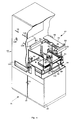
- An electronic franking system for postal items, comprising:characterised by comprising a handling mechanism (124)havinga weighing unit (66) having a receiving surface (74) and which can be activated to provide weight data concerning a postal item deposited on said receiving surface (74) and to determine a franking amount relating to said weight data; andseparating devices (77) for rendering the said weighing unit (66) inaccessible to a user during its activation;at least a moving rake (128, 129, 136, 137) disposed substantially parallel to said receiving surface (74) for moving the postal item after weighing.
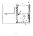
- An electronic franking system according to claim 1 characterised byat least one post box (41,42) for storing postal items, and in thatsaid handling mechanism (124) being actuatable for moving the postal item from said weighing unit (66) to said post box (41,42).
- An electronic franking system according to claim 1 or 2 characterised in that said moving rake (128, 129, 136, 137) comprises a rigid bar (128, 136) for moving thick postal items.
- An electronic franking system according to claim 1, 2 or 3 characterised in that said moving rake (128, 129, 136, 137) comprisesflexible bands (129, 137) brushing against said receiving surface (74) for moving thin or light postal items.
- An electronic franking system according to any preceding claim, characterised in that said handling mechanism (124) further comprisesan activating mechanism for moving said moving rake (128, 129) from a rest position to a working position.
- An electronic franking system according to any preceding claim characterised by:sensor devices (67) which provide signals indicating the correct positioning of the postal item in a limited zone of said receiving surface (74).
- An electronic franking system according to any preceding claim comprising a print unit (97) having a print head (98) actuatable for printing said franking amount on the postal item.
- An electronic franking system according to claim 7, characterised in that said print head (98) is actuatable for moving in X, Y and Z directions with respect to said postal item.
- An electronic franking system according to claim 7 or 8, characterised in that said print unit (97) comprisesresting means (115) associated with said print head (98) and having feedback means for stopping the movement of said print head (98) at a predetermined distance from the postal item.
- An electronic franking system according to claim 7, 8 or 9 characterised in that said print head (98) is of the inkjet type.
Priority Applications (1)
| Application Number | Priority Date | Filing Date | Title |
|---|---|---|---|
| EP99104799A EP0926642A2 (en) | 1993-09-09 | 1994-09-01 | Electronic franking system for postal items |
Applications Claiming Priority (2)
| Application Number | Priority Date | Filing Date | Title |
|---|---|---|---|
| ITTO930660 | 1993-09-09 | ||
| ITTO930660A IT1261584B (en) | 1993-09-09 | 1993-09-09 | ELECTRONIC POSTAGE ITEMS OF POSTAGE |
Related Child Applications (2)
| Application Number | Title | Priority Date | Filing Date |
|---|---|---|---|
| EP99104799A Division EP0926642A2 (en) | 1993-09-09 | 1994-09-01 | Electronic franking system for postal items |
| EP99104799.4 Division-Into | 1999-03-11 |
Publications (3)
| Publication Number | Publication Date |
|---|---|
| EP0643374A2 EP0643374A2 (en) | 1995-03-15 |
| EP0643374A3 EP0643374A3 (en) | 1996-07-24 |
| EP0643374B1 true EP0643374B1 (en) | 1999-12-01 |
Family
ID=11411720
Family Applications (2)
| Application Number | Title | Priority Date | Filing Date |
|---|---|---|---|
| EP94306446A Expired - Lifetime EP0643374B1 (en) | 1993-09-09 | 1994-09-01 | Electronic franking system comprising a mail handling mechanism |
| EP99104799A Withdrawn EP0926642A2 (en) | 1993-09-09 | 1994-09-01 | Electronic franking system for postal items |
Family Applications After (1)
| Application Number | Title | Priority Date | Filing Date |
|---|---|---|---|
| EP99104799A Withdrawn EP0926642A2 (en) | 1993-09-09 | 1994-09-01 | Electronic franking system for postal items |
Country Status (6)
| Country | Link |
|---|---|
| US (1) | US5570290A (en) |
| EP (2) | EP0643374B1 (en) |
| CA (1) | CA2131058A1 (en) |
| DE (1) | DE69421866T2 (en) |
| IT (1) | IT1261584B (en) |
| PT (1) | PT643374E (en) |
Families Citing this family (24)
| Publication number | Priority date | Publication date | Assignee | Title |
|---|---|---|---|---|
| DE59611281D1 (en) * | 1995-09-29 | 2005-11-17 | Wincor Nixdorf Int Gmbh | Device for measuring mail pieces |
| DE19880746D2 (en) * | 1997-06-05 | 2001-03-29 | Jens Zschorlich | Method and device for handling the distribution of flat mail items |
| WO1999064993A1 (en) * | 1998-06-08 | 1999-12-16 | Friendlyway Aktiengesellschaft Für Anwenderfreundliche Systeme | Mail handling device |
| AU5027799A (en) | 1998-07-31 | 2000-02-28 | Crisplant A/S | A postal item check-in system |
| FR2783337B1 (en) * | 1998-09-11 | 2000-12-15 | Neopost Ind | METHOD FOR MONITORING THE CONSUMPTION OF POSTAGE MACHINES |
| ES2164571B1 (en) * | 1999-11-24 | 2003-05-16 | Sanchez Pedro Palomo | SEALING AND SEALING MACHINE EXPENDER |
| US20010042055A1 (en) * | 2000-02-07 | 2001-11-15 | Jan Didriksen | Parcel self-servicing machine |
| EP1299198B1 (en) * | 2000-02-07 | 2004-03-31 | Crisplant A/S | A parcel self-servicing machine |
| IT1319399B1 (en) * | 2000-07-26 | 2003-10-10 | Consultbank Dott Giovanni Long | APPARATUS AND METHOD FOR ACCEPTANCE AND AUTOMATIC PROCESSING OF POSTAL PLICHES. |
| DE10114529A1 (en) * | 2001-03-21 | 2002-10-02 | Francotyp Postalia Ag | Franking machine with retrofittable weighing device |
| KR100382271B1 (en) * | 2001-10-29 | 2003-05-09 | 삼경정보통신 주식회사 | Intelligent automatic postal teller |
| US20030110083A1 (en) * | 2001-12-10 | 2003-06-12 | Taylor Jason W. | Automated point-of-sale terminal for use in a post office |
| SE521332C2 (en) * | 2002-04-16 | 2003-10-21 | Styrbjoern Gaerde | Automatic dispatch and handling procedure |
| US7065492B2 (en) * | 2002-07-11 | 2006-06-20 | Laura Cinquini | Method and apparatus for providing a personal item drop off/return service at security checkpoints |
| DE10246127A1 (en) * | 2002-10-01 | 2004-04-15 | Wincor Nixdorf International Gmbh | Postgutmessvorrichtung |
| GB2405515A (en) * | 2003-08-28 | 2005-03-02 | Amanda Bothwell | Self-service mailing apparatus |
| US20050065643A1 (en) * | 2003-09-22 | 2005-03-24 | Elefante Daniel A. | Method and apparatus for recovery of prohibited items |
| ES2247932B1 (en) * | 2004-06-08 | 2007-06-16 | Pilar Espasa Sanchez | MACHINE FOR RECEPTION, IDENTIFICATION AND CLASSIFICATION OF PACKAGES FOR MESSAGING. |
| WO2006098728A2 (en) * | 2005-03-11 | 2006-09-21 | Amerisource Companies, Lp | Method and system for item delivery |
| US7708630B2 (en) | 2005-12-09 | 2010-05-04 | Igt | Rotor-based gaming device having a system for changing the quantity of potential game outcomes for subsequent plays |
| US9776525B2 (en) * | 2014-09-02 | 2017-10-03 | Move Systems International, Llc | Anti-idling system for ambulances and other vehicles |
| CN104299325A (en) * | 2014-11-17 | 2015-01-21 | 章玺 | Intelligent express box with infrared touch screen |
| CN104537773B (en) * | 2015-01-22 | 2017-01-18 | 廖友谊 | Collection type self-service express taking and pickup method and self-service express taking machine |
| PL232013B1 (en) * | 2015-10-28 | 2019-04-30 | Asapon Spolka Z Ograniczona Odpowiedzialnoscia | Device for sending parcels and method for sending parcels |
Family Cites Families (12)
| Publication number | Priority date | Publication date | Assignee | Title |
|---|---|---|---|---|
| US3290491A (en) * | 1961-06-19 | 1966-12-06 | Eric C Wahlberg | Automatic mailing machine |
| US4024380A (en) * | 1971-01-18 | 1977-05-17 | Damon Mott Gunn | Self service postal apparatus and method |
| US3866235A (en) * | 1973-05-10 | 1975-02-11 | Mosler Safe Co | Depository for imprinting and storing envelopes containing paper currency and/or coins |
| US4868757A (en) * | 1983-12-16 | 1989-09-19 | Pi Electronics Corporation | Computerized integrated electronic mailing/addressing apparatus |
| US4956782A (en) * | 1986-09-19 | 1990-09-11 | Pitney Bowes Inc. | Mailing system for mixed weight mail |
| US5272640A (en) * | 1986-10-17 | 1993-12-21 | Wu Sheng J | Automatic mail-processing device with full functions |
| AU599336B2 (en) * | 1986-10-17 | 1990-07-19 | Wu Sheng-Jung | Microcomputerized automatic post counter |
| US4900905A (en) * | 1988-08-01 | 1990-02-13 | Pavo Pusic | Automated mail collecting and telecommunication machine |
| US5025386A (en) * | 1988-08-01 | 1991-06-18 | Pavo Pusic | Automated mail collecting and telecommunication machine II |
| US4923022B1 (en) * | 1989-04-25 | 1994-04-12 | Hsieh Tzu Yen | Automatic mailing apparatus |
| US5233532A (en) * | 1991-04-10 | 1993-08-03 | U-Ship Usa, Ltd. | System for mailing and collecting items |
| US5481464A (en) * | 1991-04-10 | 1996-01-02 | U-Ship, Inc. | System for collecting and shipping items |
-
1993
- 1993-09-09 IT ITTO930660A patent/IT1261584B/en active IP Right Grant
-
1994
- 1994-08-26 US US08/297,555 patent/US5570290A/en not_active Expired - Fee Related
- 1994-08-29 CA CA002131058A patent/CA2131058A1/en not_active Abandoned
- 1994-09-01 PT PT94306446T patent/PT643374E/en unknown
- 1994-09-01 DE DE69421866T patent/DE69421866T2/en not_active Expired - Fee Related
- 1994-09-01 EP EP94306446A patent/EP0643374B1/en not_active Expired - Lifetime
- 1994-09-01 EP EP99104799A patent/EP0926642A2/en not_active Withdrawn
Also Published As
| Publication number | Publication date |
|---|---|
| CA2131058A1 (en) | 1995-03-10 |
| EP0643374A2 (en) | 1995-03-15 |
| DE69421866D1 (en) | 2000-01-05 |
| EP0643374A3 (en) | 1996-07-24 |
| PT643374E (en) | 2000-05-31 |
| DE69421866T2 (en) | 2000-06-29 |
| US5570290A (en) | 1996-10-29 |
| ITTO930660A0 (en) | 1993-09-09 |
| EP0926642A2 (en) | 1999-06-30 |
| IT1261584B (en) | 1996-05-23 |
| ITTO930660A1 (en) | 1995-03-09 |
Similar Documents
| Publication | Publication Date | Title |
|---|---|---|
| EP0643374B1 (en) | Electronic franking system comprising a mail handling mechanism | |
| US6477514B1 (en) | Automated self-service mail processing and storing systems | |
| US6105014A (en) | Automated package shipping machine | |
| US4836352A (en) | Express package collection locker | |
| EP0579717B1 (en) | System and method for mailing and collecting items | |
| JP3461507B2 (en) | Automatic teller machine | |
| US5415264A (en) | Automatic vending machine for newspapers | |
| US20080133372A1 (en) | Automated package shipping machine | |
| US20020007281A1 (en) | Automated self-service mail processing and storing systems | |
| US5251738A (en) | Currency handling system | |
| US4900905A (en) | Automated mail collecting and telecommunication machine | |
| JPH02286501A (en) | Self-service type transaction device and its method | |
| WO1994004446A1 (en) | An apparatus for storing and dispensing articles | |
| KR100382271B1 (en) | Intelligent automatic postal teller | |
| EP1713034B1 (en) | Self-service mail accepting machine | |
| US6917924B1 (en) | Automated package shipping machine | |
| US3112019A (en) | Depository apparatus | |
| JP2653221B2 (en) | Card issuing device | |
| KR20000007887U (en) | Unmanned Window System for Mail Reception | |
| JP3784899B2 (en) | Automatic record recovery device | |
| WO2001004704A1 (en) | Automatic machine for dispensing photographic items and the like | |
| JPH11232346A (en) | Window-use stamp storage management device and stamp sales management system using the same |
Legal Events
| Date | Code | Title | Description |
|---|---|---|---|
| PUAI | Public reference made under article 153(3) epc to a published international application that has entered the european phase |
Free format text: ORIGINAL CODE: 0009012 |
|
| AK | Designated contracting states |
Kind code of ref document: A2 Designated state(s): DE FR GB PT |
|
| PUAL | Search report despatched |
Free format text: ORIGINAL CODE: 0009013 |
|
| AK | Designated contracting states |
Kind code of ref document: A3 Designated state(s): DE FR GB PT |
|
| 17P | Request for examination filed |
Effective date: 19970108 |
|
| 17Q | First examination report despatched |
Effective date: 19970326 |
|
| RAP1 | Party data changed (applicant data changed or rights of an application transferred) |
Owner name: OLIVETTI SOLUTIONS S.P.A. |
|
| GRAG | Despatch of communication of intention to grant |
Free format text: ORIGINAL CODE: EPIDOS AGRA |
|
| GRAG | Despatch of communication of intention to grant |
Free format text: ORIGINAL CODE: EPIDOS AGRA |
|
| GRAH | Despatch of communication of intention to grant a patent |
Free format text: ORIGINAL CODE: EPIDOS IGRA |
|
| RAP1 | Party data changed (applicant data changed or rights of an application transferred) |
Owner name: WANG GLOBAL SPA |
|
| GRAH | Despatch of communication of intention to grant a patent |
Free format text: ORIGINAL CODE: EPIDOS IGRA |
|
| GRAA | (expected) grant |
Free format text: ORIGINAL CODE: 0009210 |
|
| AK | Designated contracting states |
Kind code of ref document: B1 Designated state(s): DE FR GB PT |
|
| REF | Corresponds to: |
Ref document number: 69421866 Country of ref document: DE Date of ref document: 20000105 |
|
| ET | Fr: translation filed | ||
| RAP2 | Party data changed (patent owner data changed or rights of a patent transferred) |
Owner name: GETRONICS SOLUTIONS ITALIA S.P.A. |
|
| REG | Reference to a national code |
Ref country code: PT Ref legal event code: SC4A Free format text: AVAILABILITY OF NATIONAL TRANSLATION Effective date: 20000210 |
|
| PGFP | Annual fee paid to national office [announced via postgrant information from national office to epo] |
Ref country code: GB Payment date: 20000830 Year of fee payment: 7 |
|
| PGFP | Annual fee paid to national office [announced via postgrant information from national office to epo] |
Ref country code: PT Payment date: 20000831 Year of fee payment: 7 |
|
| PGFP | Annual fee paid to national office [announced via postgrant information from national office to epo] |
Ref country code: DE Payment date: 20000904 Year of fee payment: 7 |
|
| PGFP | Annual fee paid to national office [announced via postgrant information from national office to epo] |
Ref country code: FR Payment date: 20000912 Year of fee payment: 7 |
|
| PLBE | No opposition filed within time limit |
Free format text: ORIGINAL CODE: 0009261 |
|
| STAA | Information on the status of an ep patent application or granted ep patent |
Free format text: STATUS: NO OPPOSITION FILED WITHIN TIME LIMIT |
|
| 26N | No opposition filed | ||
| PG25 | Lapsed in a contracting state [announced via postgrant information from national office to epo] |
Ref country code: GB Free format text: LAPSE BECAUSE OF NON-PAYMENT OF DUE FEES Effective date: 20010901 |
|
| PG25 | Lapsed in a contracting state [announced via postgrant information from national office to epo] |
Ref country code: PT Free format text: LAPSE BECAUSE OF NON-PAYMENT OF DUE FEES Effective date: 20020331 |
|
| PG25 | Lapsed in a contracting state [announced via postgrant information from national office to epo] |
Ref country code: DE Free format text: LAPSE BECAUSE OF NON-PAYMENT OF DUE FEES Effective date: 20020501 |
|
| PG25 | Lapsed in a contracting state [announced via postgrant information from national office to epo] |
Ref country code: FR Free format text: LAPSE BECAUSE OF NON-PAYMENT OF DUE FEES Effective date: 20020531 |
|
| REG | Reference to a national code |
Ref country code: FR Ref legal event code: ST |
|
| REG | Reference to a national code |
Ref country code: PT Ref legal event code: MM4A Free format text: LAPSE DUE TO NON-PAYMENT OF FEES Effective date: 20020331 |