EP0639933A2 - Method and apparatus for processing an audio signal by surround modes - Google Patents
Method and apparatus for processing an audio signal by surround modes Download PDFInfo
- Publication number
- EP0639933A2 EP0639933A2 EP94305964A EP94305964A EP0639933A2 EP 0639933 A2 EP0639933 A2 EP 0639933A2 EP 94305964 A EP94305964 A EP 94305964A EP 94305964 A EP94305964 A EP 94305964A EP 0639933 A2 EP0639933 A2 EP 0639933A2
- Authority
- EP
- European Patent Office
- Prior art keywords
- surround
- audio signal
- signal
- processing
- sound
- Prior art date
- Legal status (The legal status is an assumption and is not a legal conclusion. Google has not performed a legal analysis and makes no representation as to the accuracy of the status listed.)
- Granted
Links
Images


Classifications
-
- H—ELECTRICITY
- H04—ELECTRIC COMMUNICATION TECHNIQUE
- H04N—PICTORIAL COMMUNICATION, e.g. TELEVISION
- H04N5/00—Details of television systems
- H04N5/44—Receiver circuitry for the reception of television signals according to analogue transmission standards
- H04N5/60—Receiver circuitry for the reception of television signals according to analogue transmission standards for the sound signals
- H04N5/607—Receiver circuitry for the reception of television signals according to analogue transmission standards for the sound signals for more than one sound signal, e.g. stereo, multilanguages
-
- H—ELECTRICITY
- H04—ELECTRIC COMMUNICATION TECHNIQUE
- H04S—STEREOPHONIC SYSTEMS
- H04S3/00—Systems employing more than two channels, e.g. quadraphonic
- H04S3/02—Systems employing more than two channels, e.g. quadraphonic of the matrix type, i.e. in which input signals are combined algebraically, e.g. after having been phase shifted with respect to each other
-
- H—ELECTRICITY
- H04—ELECTRIC COMMUNICATION TECHNIQUE
- H04S—STEREOPHONIC SYSTEMS
- H04S1/00—Two-channel systems
- H04S1/002—Non-adaptive circuits, e.g. manually adjustable or static, for enhancing the sound image or the spatial distribution
-
- H—ELECTRICITY
- H04—ELECTRIC COMMUNICATION TECHNIQUE
- H04S—STEREOPHONIC SYSTEMS
- H04S5/00—Pseudo-stereo systems, e.g. in which additional channel signals are derived from monophonic signals by means of phase shifting, time delay or reverberation
- H04S5/02—Pseudo-stereo systems, e.g. in which additional channel signals are derived from monophonic signals by means of phase shifting, time delay or reverberation of the pseudo four-channel type, e.g. in which rear channel signals are derived from two-channel stereo signals
-
- H—ELECTRICITY
- H04—ELECTRIC COMMUNICATION TECHNIQUE
- H04S—STEREOPHONIC SYSTEMS
- H04S2420/00—Techniques used stereophonic systems covered by H04S but not provided for in its groups
- H04S2420/13—Application of wave-field synthesis in stereophonic audio systems
Definitions
- the present invention relates to an audio signal processing apparatus and more particularly to an apparatus and method for processing an audio signal by surround modes in which a surround-sound of an original sound in accordance with surround modes can be reproduced by carrying surround code information to the audio signal being transmitted and by detecting the surround code information upon receipt of the audio signal.
- audio sets having a surround circuit capable of providing the surround-sound of a current sound, ie the audio-impression of the sound field where an original sound is produced, to a listener are installed have been now popularised.
- the surround-sound is capable of reproducing the audio-impression of a sound field by generating an inherent reflected sound responsive to an audio signal.
- FIG. 1 shows an audio apparatus in which the surround circuit is installed, which is disclosed in Korean patent application 92-7759 filed by the applicant of the present application.
- a surround unit 14 has a plurality of surround circuits 14a, 14b and 14c which delay the audio signal applied from left and right audio input terminals L and R to represent a surround-sound effect different from each other.
- a switch 16 connects one of the surround circuits 14a, 14b and 14c to left and right surround exclusive speakers SSP1 and SSP2.
- a controller 18, for example, a micro computer serves to control the switch 16.
- a sound adjustor 10 adjusts a base, balance, treble and volume of the audio signal and then outputs the adjusted audio signal through speakers SP1 and SP2.
- An amplifier 12 is connected to an output terminal of the sound adjustor 10 and amplifies the audio signal supplied to the speakers SP1 and SP2.
- the audio apparatus shown in Figure 1 has an advantage of providing a variable surround-sound effect to a user by installing therein a plurality of surround circuits each of which generate a surround-sound effect different from the others.
- the surround-sound effect to be desired can not be generated fully.
- a method for processing an audio signal in which in a transmitting side, the audio signal is transmitted and in a receiving side, said audio signal is surround-processed comprising the steps of: mixing said audio signal with surround-sound information indicating a surround-sound characteristic in response to original sound timbre in the transmitting side; transmitting the mixed signal in the transmitting side and receiving said mixed signal in the receiving side; separating said audio signal and said surround-sound information from said mixed signal; and surround-processing said audio signal to an audio signal having the surround-sound indicated by said surround-sound information.
- a method of processing transmission/reception of an audio signal in which in a transmitting side, the audio signal is transmitted and in a receiving side, the surround-sound of the audio signal is processed and output in one of the methods of forming a plural surround signal, comprises the steps of transmitting surround code information indicating a surround sound signal forming method adequate to the audio signal with the audio signal, in the transmitting side and of processing the audio signal in the surround signal forming method designated as the surround code information.
- an apparatus for processing an audio signal having a transmitting device which transmits said audio signal and a receiving device which surround-processes said audio signal from the surround-processed audio signal
- said apparatus comprising: said transmitting device comprising means for generating a surround discriminating signal indicating a surround mode appropriate to the audio signal of an original sound, and mixing means for mixing said surround discriminating signal with said audio signal; and said receiving device comprising separating means for separating said surround discriminating signal from said surround-processed audio signal, a surround mode detector for detecting a surround mode from said surround discriminating signal separated by said separating means, and surround-sound processing means for surround-processing said audio signal in response to the detection result of said surround mode.
- an apparatus for processing transmission/reception of an audio signal having a transmitting device in which the audio signal is transmitted and a receiving device in which the audio signal is surround-processed via a surround processor and is output comprises the transmitting device which is made up of means for generating a surround discriminating signal indicating a surround mode adequate to the audio signal and a mixer for mixing the surround discriminating signal with the audio signal, and the receiving device which is made up of a separator for separating the surround discriminating signal from the audio signal and of a demodulator connected to the separator for recognising the surround mode from the surround discriminating signal to control the surround processor and for performing the surround-process adequate to the audio signal.
- a reference numeral 20 represents an audio signal generator and 22 represents a surround discriminating signal generator which frequency-modulates surround code information appropriate to the audio signal and outputs the frequency-modulated surround code information.
- a reference numeral 24 represents a mixer which mixes the frequency-modulated surround code information with the audio signal, and 26 represents a transmitter.
- a reference numeral 30 represents a receiver and 34 represents a high band-pass filter which filters high bandwidth to extract the surround code information in a receiving signal.
- a reference numeral 32 represents a low band-pass filter which filters low bandwidth to extract the audio signal in the receiving signal and 36 represents a surround code information detector which detects the surround code information.
- a reference numeral 38 represents a surround processor which assigns a surround-sound corresponding to surround information by codes to the audio signal in accordance with the detected surround code information.
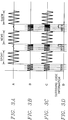
- FIGS 3A to 3D are waveforms showing the operation of Figure 2. Hereinafter, details of the operation of Figure 2 will be explained with reference to Figures 3A to 3D.
- Figure 3A shows waveforms of the audio signals output from an audio signal generator 20 of a transmitting side of a broadcasting station, which may be that of news produced in a hall, a show performed in a concert hall, or a sport played in a sportsground.
- the surround code information corresponding to a broadcasting program shown in Figure 3A is applied to the surround discriminating signal generator 22.
- the surround code information is composed of digital values of a binary logic constituted as a preset bit, which is previously determined in a transmitting/receiving side of the broadcasting station.
- the surround discriminating signal generator 22 modulates the surround code information into a modulated analog signal as shown in Figure 3B.
- the modulated analog signal is applied to the mixer 24.
- Figure 3B shows a surround discriminating signal modulated from the surround code information corresponding to respective different places of Figure 3A.
- the frequency of the surround discriminating signal is 30 KHz.
- the frequency of the surround discriminating signal is 40 KHz. It is apparent to those skilled in the art that the frequency bandwidth of the surround discriminating signal is arbitrarily variable within the limit that it does not interfere with the frequency bandwidth of the original audio signal.
- Surround Code Information Corresponding Place to Surround Code Information 0 0 0 0 0 Concert Hall 1 0 0 0 1 Concert hall 2 0 0 1 0 Sportsground ⁇ ⁇ ⁇ ⁇ ⁇ 1 1 1 1 Theater TABLE ⁇ 1>
- the audio signal and the surround discriminating signal respectively output from the audio signal generator 20 and the surround discriminating signal generator 22 are mixed in the mixer 24, as shown in Figure 3C.
- the mixed signal in the mixer 24 is applied to the transmitter 26.
- the transmitter 26 converts the mixed signal in accordance with the format of the television signal to thereby transmit the converted television signal to the receiving side of a television receiving device.
- the mixed signal transmitted from the transmitter 26 of Figure 2A is received by the receiver 30.
- the mixed signal which is received by the receiver 30 has the audio signal and the surround discriminating signal.
- the audio signal is extracted through the low band-pass filter 32 and simultaneously the surround discriminating signal is extracted through the high band-pass filter 34.
- the surround discriminating signal uses the frequency bandwidth of the 30 KHz and 40 KHz in the present invention
- the low band-pass filter 32 and the high bandpass filter 34 have a cut-off frequency of 30 KHz.
- the cut-off frequencies of the low and high band-pass filters 32 and 34 should not be superposed on each other.
- the surround code information detector 36 detects the surround code information as shown in Figure 3D from the surround discriminating signal output from the high bandpass filter 34 and then outputs the surround code information to the surround processor 38.
- the surround processor 38 performs a surround-process of the audio signal output from the low band-pass filter 32 in accordance with the surround code information output from the surround code information detector 36 to output the surround-processed audio signal.
- the surround mode corresponding to the surround code information has previously been agreed upon with the transmitting side of the broadcasting station for instance as set out in Table ⁇ 1> above.
- the surround processor 38 can automatically output the surround-processed audio signal corresponding to the surround mode without the surround mode having to be selected by a conventional user.
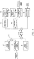
- Figure 4 shows an apparatus for processing the transmission/reception of an audio signal according to the present invention in this case embodied in a video recorder.
- the surround discriminating signal generated from a surround discriminating signal generator 42 and the audio signal generated from an audio signal generator 40 are mixed in a mixer 44.
- the mixed signals are frequency-modulated in a modulator 48 to be recorded in a tape (not shown) through a recording head 46.
- the audio/video signals recorded as set out above are reproduced through the following process.
- the audio/video signals recorded in the tape are read through a playback head 50, and the audio signal (mixed with the surround discriminating signal) and the video signal are respectively demodulated through a demodulator 62.
- the audio signal mixed with the surround discriminating signal demodulated in the demodulator 62 are respectively separated into an audio signal and a surround discriminating signal via high and low band-pass filters 52 and 54.
- the surround discriminating signal output from the high band-pass filter 52 is applied to the surround code information detector 56, and the audio signal output from the low band-pass filter 54 is applied to the surround-sound generator 60.
- the surround code information detector 56 detects the surround code information from the surround discriminating signal output from the low band-pass filter 54 and thereby, a surround mode controller 58 controls a surround-sound generator 60 in correspondence with the surround code information.
- the surround mode controller 58 can use a micro computer, wherein the surround mode corresponding to the surround code information has been established.
- the surround mode controller 58 outputs a surround mode signal previously established in response to the surround code information.
- the surround-sound generator 60 assigns a given surround-sound to the audio signal output from the low band-pass filter 54 in response to the surround mode signal output from the surround mode controller 58 and then outputs the surround-processed audio signal.
- a video signal processor 64 processes the video signal separated in the demodulator 62. Through such a reproducing process, it will be understood that the surround-sound recorded in the video record tape is reproduced like the surround-sound of an original sound.
- an apparatus and method for processing an audio signal by surround modes have an advantage of fully reproducing a surround-sound of an original sound by transmitting or recording a surround discriminating signal indicating a surround mode with the audio signal and by detecting or reproducing the surround discriminating signal to control the surround mode.
Abstract
Description
- The present invention relates to an audio signal processing apparatus and more particularly to an apparatus and method for processing an audio signal by surround modes in which a surround-sound of an original sound in accordance with surround modes can be reproduced by carrying surround code information to the audio signal being transmitted and by detecting the surround code information upon receipt of the audio signal.
- In general, audio sets having a surround circuit capable of providing the surround-sound of a current sound, ie the audio-impression of the sound field where an original sound is produced, to a listener are installed have been now popularised. Unlike stereo, the surround-sound is capable of reproducing the audio-impression of a sound field by generating an inherent reflected sound responsive to an audio signal.
- Figure 1 shows an audio apparatus in which the surround circuit is installed, which is disclosed in Korean patent application 92-7759 filed by the applicant of the present application. A
surround unit 14 has a plurality ofsurround circuits switch 16 connects one of thesurround circuits switch 16. Asound adjustor 10 adjusts a base, balance, treble and volume of the audio signal and then outputs the adjusted audio signal through speakers SP1 and SP2. Anamplifier 12 is connected to an output terminal of thesound adjustor 10 and amplifies the audio signal supplied to the speakers SP1 and SP2. - The audio apparatus shown in Figure 1 has an advantage of providing a variable surround-sound effect to a user by installing therein a plurality of surround circuits each of which generate a surround-sound effect different from the others.
- However, there is much inconvenience in using the audio apparatus shown in Figure 1, since the surround circuits which generate a surround-sound effect corresponding to the surround-sound characteristic of an original sound in a hall, concert, sportsground, theater, etc need to be individually selected by a user in accordance with the surround-sound characteristic.
- Moreover, when the surround-sound characteristic of the original sound is not matched with the characteristic of the surround circuit selected by the user, the surround-sound effect to be desired can not be generated fully.
- It is therefore one aim of embodiments of the present invention to provide a method for processing an audio signal by automatically selecting a surround mode corresponding to a surround-sound characteristic of an original sound.
- It is another aim of embodiments of the present invention to provide an adequate apparatus to the method for processing an audio signal as mentioned in the above aim.
- According to the present invention, there is provided a method for processing an audio signal in which in a transmitting side, the audio signal is transmitted and in a receiving side, said audio signal is surround-processed, said method comprising the steps of: mixing said audio signal with surround-sound information indicating a surround-sound characteristic in response to original sound timbre in the transmitting side; transmitting the mixed signal in the transmitting side and receiving said mixed signal in the receiving side; separating said audio signal and said surround-sound information from said mixed signal; and surround-processing said audio signal to an audio signal having the surround-sound indicated by said surround-sound information.
- Thus, there is provided a method of processing transmission/reception of an audio signal, in which in a transmitting side, the audio signal is transmitted and in a receiving side, the surround-sound of the audio signal is processed and output in one of the methods of forming a plural surround signal, comprises the steps of transmitting surround code information indicating a surround sound signal forming method adequate to the audio signal with the audio signal, in the transmitting side and of processing the audio signal in the surround signal forming method designated as the surround code information.
- According to the present invention, there is also provided an apparatus for processing an audio signal having a transmitting device which transmits said audio signal and a receiving device which surround-processes said audio signal from the surround-processed audio signal, said apparatus comprising: said transmitting device comprising means for generating a surround discriminating signal indicating a surround mode appropriate to the audio signal of an original sound, and mixing means for mixing said surround discriminating signal with said audio signal; and said receiving device comprising separating means for separating said surround discriminating signal from said surround-processed audio signal, a surround mode detector for detecting a surround mode from said surround discriminating signal separated by said separating means, and surround-sound processing means for surround-processing said audio signal in response to the detection result of said surround mode.
- Thus, there is also provided an apparatus for processing transmission/reception of an audio signal having a transmitting device in which the audio signal is transmitted and a receiving device in which the audio signal is surround-processed via a surround processor and is output, comprises the transmitting device which is made up of means for generating a surround discriminating signal indicating a surround mode adequate to the audio signal and a mixer for mixing the surround discriminating signal with the audio signal, and the receiving device which is made up of a separator for separating the surround discriminating signal from the audio signal and of a demodulator connected to the separator for recognising the surround mode from the surround discriminating signal to control the surround processor and for performing the surround-process adequate to the audio signal.
- These and other features and advantages of the present invention will be better understood by a reading of the following detailed description of an embodiment of the invention by way of example only, taken in conjunction with the accompanying drawings. In the drawings, it should be noted that like elements represent like symbols or reference numerals, wherein:
- Figure 1 is a block diagram showing a conventional audio apparatus having a surround processor;
- Figures 2A and 2B are block diagrams showing an apparatus for processing transmission/reception of an audio signal according to the present invention;
- Figures 3A to 3D are waveforms showing input/output states of the apparatus for processing an audio signal of Figure 2; and
- Figure 4 is a block diagram showing an embodiment of an apparatus for processing an audio signal according to the present invention.
- Referring to Figures 2A and 2B as block diagrams showing a preferred embodiment of an apparatus for processing transmission/reception of an audio signal according to the present invention, in a transmitting device of Figure 2A, a
reference numeral 20 represents an audio signal generator and 22 represents a surround discriminating signal generator which frequency-modulates surround code information appropriate to the audio signal and outputs the frequency-modulated surround code information. Areference numeral 24 represents a mixer which mixes the frequency-modulated surround code information with the audio signal, and 26 represents a transmitter. - In a receiving device of Figure 2B, a
reference numeral 30 represents a receiver and 34 represents a high band-pass filter which filters high bandwidth to extract the surround code information in a receiving signal. Further, areference numeral 32 represents a low band-pass filter which filters low bandwidth to extract the audio signal in the receiving signal and 36 represents a surround code information detector which detects the surround code information. Areference numeral 38 represents a surround processor which assigns a surround-sound corresponding to surround information by codes to the audio signal in accordance with the detected surround code information. - Figures 3A to 3D are waveforms showing the operation of Figure 2. Hereinafter, details of the operation of Figure 2 will be explained with reference to Figures 3A to 3D.
- In the case of the illustrative embodiment of Figure 2 as a television system, in a transmitting side, an audio signal and a video signal are processed through separate paths and converted into a radio frequency RF signal to output the converted signal. Herein, since explanation of a video signal process in the embodiment of Figure 2A is unnecessary for the person skilled in the art, it will be avoided herein in order to assist in the explanation of the present invention.
- Figure 3A shows waveforms of the audio signals output from an
audio signal generator 20 of a transmitting side of a broadcasting station, which may be that of news produced in a hall, a show performed in a concert hall, or a sport played in a sportsground. - At this time, in the transmitting side of the broadcasting station, the surround code information corresponding to a broadcasting program shown in Figure 3A is applied to the surround
discriminating signal generator 22. The surround code information is composed of digital values of a binary logic constituted as a preset bit, which is previously determined in a transmitting/receiving side of the broadcasting station. The surrounddiscriminating signal generator 22 modulates the surround code information into a modulated analog signal as shown in Figure 3B. The modulated analog signal is applied to themixer 24. - Figure 3B shows a surround discriminating signal modulated from the surround code information corresponding to respective different places of Figure 3A. Here, when the binary code of the surround code information is "0", the frequency of the surround discriminating signal is 30 KHz. On the other hand, when the binary code of the surround code information is "1", the frequency of the surround discriminating signal is 40 KHz. It is apparent to those skilled in the art that the frequency bandwidth of the surround discriminating signal is arbitrarily variable within the limit that it does not interfere with the frequency bandwidth of the original audio signal.
- The example of classification of the surround code information is indicated by the following TABLE <1>.
Surround Code Information Corresponding Place to Surround Code Information 0 0 0 0 Concert Hall 1 0 0 0 1 Concert hall 2 0 0 1 0 Sportsground · · · · · · 1 1 1 1 Theater TABLE <1> - The audio signal and the surround discriminating signal respectively output from the
audio signal generator 20 and the surrounddiscriminating signal generator 22 are mixed in themixer 24, as shown in Figure 3C. The mixed signal in themixer 24 is applied to thetransmitter 26. Thetransmitter 26 converts the mixed signal in accordance with the format of the television signal to thereby transmit the converted television signal to the receiving side of a television receiving device. - In the receiving device of Figure 2B, the mixed signal transmitted from the
transmitter 26 of Figure 2A is received by thereceiver 30. The mixed signal which is received by thereceiver 30 has the audio signal and the surround discriminating signal. Then, the audio signal is extracted through the low band-pass filter 32 and simultaneously the surround discriminating signal is extracted through the high band-pass filter 34. Since the surround discriminating signal uses the frequency bandwidth of the 30 KHz and 40 KHz in the present invention, the low band-pass filter 32 and thehigh bandpass filter 34 have a cut-off frequency of 30 KHz. Preferably, the cut-off frequencies of the low and high band-pass filters - The surround
code information detector 36 detects the surround code information as shown in Figure 3D from the surround discriminating signal output from thehigh bandpass filter 34 and then outputs the surround code information to thesurround processor 38. Thus, thesurround processor 38 performs a surround-process of the audio signal output from the low band-pass filter 32 in accordance with the surround code information output from the surroundcode information detector 36 to output the surround-processed audio signal. It should be noted that in thesurround processor 38 the surround mode corresponding to the surround code information has previously been agreed upon with the transmitting side of the broadcasting station for instance as set out in Table <1> above. Thesurround processor 38 can automatically output the surround-processed audio signal corresponding to the surround mode without the surround mode having to be selected by a conventional user. - Figure 4 shows an apparatus for processing the transmission/reception of an audio signal according to the present invention in this case embodied in a video recorder.
- Details of a process of recording the audio/video signals will be hereinafter explained with reference to Figure 4.
- The surround discriminating signal generated from a surround
discriminating signal generator 42 and the audio signal generated from anaudio signal generator 40 are mixed in a mixer 44. The mixed signals are frequency-modulated in amodulator 48 to be recorded in a tape (not shown) through a recording head 46. - The audio/video signals recorded as set out above are reproduced through the following process.
- The audio/video signals recorded in the tape are read through a playback head 50, and the audio signal (mixed with the surround discriminating signal) and the video signal are respectively demodulated through a
demodulator 62. Here, the audio signal mixed with the surround discriminating signal demodulated in thedemodulator 62 are respectively separated into an audio signal and a surround discriminating signal via high and low band-pass filters pass filter 52 is applied to the surroundcode information detector 56, and the audio signal output from the low band-pass filter 54 is applied to the surround-sound generator 60. The surroundcode information detector 56 detects the surround code information from the surround discriminating signal output from the low band-pass filter 54 and thereby, asurround mode controller 58 controls a surround-sound generator 60 in correspondence with the surround code information. Thesurround mode controller 58 can use a micro computer, wherein the surround mode corresponding to the surround code information has been established. Thesurround mode controller 58 outputs a surround mode signal previously established in response to the surround code information. Then, the surround-sound generator 60 assigns a given surround-sound to the audio signal output from the low band-pass filter 54 in response to the surround mode signal output from thesurround mode controller 58 and then outputs the surround-processed audio signal. Avideo signal processor 64 processes the video signal separated in thedemodulator 62. Through such a reproducing process, it will be understood that the surround-sound recorded in the video record tape is reproduced like the surround-sound of an original sound. - As hereinbefore explained, an apparatus and method for processing an audio signal by surround modes according to the present invention have an advantage of fully reproducing a surround-sound of an original sound by transmitting or recording a surround discriminating signal indicating a surround mode with the audio signal and by detecting or reproducing the surround discriminating signal to control the surround mode.
- The reader's attention is directed to all papers and documents which are filed concurrently with or previous to this specification in connection with this application and which are open to public inspection with this specification, and the contents of all such papers and documents are incorporated herein by reference.
- All of the features disclosed in this specification (including any accompanying claims, abstract and drawings), and/or all of the steps of any method or process so disclosed, may be combined in any combination, except combinations where at least some of such features and/or steps are mutually exclusive.
- Each feature disclosed in this specification (including any accompanying claims, abstract and drawings), may be replaced by alternative features serving the same, equivalent or similar purpose, unless expressly stated otherwise. Thus, unless expressly stated otherwise, each feature disclosed is one example only of a generic series of equivalent or similar features.
- The invention is not restricted to the details of the foregoing embodiment(s). The invention extends to any novel one, or any novel combination, of the features disclosed in this specification (including any accompanying claims, abstract and drawings), or to any novel one, or any novel combination, of the steps of any method or process so disclosed.
Claims (8)
mixing said audio signal with surround-sound information indicating a surround-sound characteristic in response to original sound timbre in the transmitting side;
transmitting the mixed signal in the transmitting side and receiving said mixed signal in the receiving side;
separating said audio signal and said surround-sound information from said mixed signal; and
surround-processing said audio signal to an audio signal having the surround-sound indicated by said surround-sound information.
said transmitting device (26, 46) comprising means (22, 42) for generating a surround discriminating signal indicating a surround mode appropriate to the audio signal of an original sound, and mixing means (24, 44) for mixing said surround discriminating signal with said audio signal; and
said receiving device (30, 50) comprising separating means (32, 34, 52, 54) for separating said surround discriminating signal from said surround-processed audio signal, a surround mode detector (36, 56) for detecting a surround mode from said surround discriminating signal separated by said separating means (32, 34, 52, 54), and surround-sound processing means (38, 58, 60) for surround-processing said audio signal in response to the detection result of said surround mode.
Applications Claiming Priority (2)
| Application Number | Priority Date | Filing Date | Title |
|---|---|---|---|
| KR1019930016139A KR0123755B1 (en) | 1993-08-19 | 1993-08-19 | Voice signal transceiver system |
| KR1613993 | 1993-08-19 |
Publications (3)
| Publication Number | Publication Date |
|---|---|
| EP0639933A2 true EP0639933A2 (en) | 1995-02-22 |
| EP0639933A3 EP0639933A3 (en) | 1995-11-02 |
| EP0639933B1 EP0639933B1 (en) | 2003-11-26 |
Family
ID=19361609
Family Applications (1)
| Application Number | Title | Priority Date | Filing Date |
|---|---|---|---|
| EP94305964A Expired - Lifetime EP0639933B1 (en) | 1993-08-19 | 1994-08-11 | Method and apparatus for processing an audio signal by surround modes |
Country Status (4)
| Country | Link |
|---|---|
| US (1) | US5602922A (en) |
| EP (1) | EP0639933B1 (en) |
| KR (1) | KR0123755B1 (en) |
| DE (1) | DE69433349T2 (en) |
Families Citing this family (8)
| Publication number | Priority date | Publication date | Assignee | Title |
|---|---|---|---|---|
| US5717765A (en) * | 1994-03-07 | 1998-02-10 | Sony Corporation | Theater sound system with upper surround channels |
| JP2766466B2 (en) * | 1995-08-02 | 1998-06-18 | 株式会社東芝 | Audio system, reproduction method, recording medium and recording method on recording medium |
| US5953067A (en) * | 1997-02-10 | 1999-09-14 | Cable Electronics, Inc. | Multichannel television sound stereo and surround sound encoder |
| NO307728B1 (en) * | 1997-06-03 | 2000-05-15 | Abb Research Ltd | Steps to obtain time synchronization on a network |
| US6288747B1 (en) | 1997-08-25 | 2001-09-11 | Cable Electronics, Inc. | Multichannel television sound stereo and surround sound encoder suitable for use with video signals encoded in plural formats |
| US6587682B2 (en) * | 2001-01-18 | 2003-07-01 | Polycom, Inc. | Signal routing for reduced power consumption in a conferencing system |
| US7355561B1 (en) | 2003-09-15 | 2008-04-08 | United States Of America As Represented By The Secretary Of The Army | Systems and methods for providing images |
| KR102443054B1 (en) * | 2014-03-24 | 2022-09-14 | 삼성전자주식회사 | Method and apparatus for rendering acoustic signal, and computer-readable recording medium |
Citations (6)
| Publication number | Priority date | Publication date | Assignee | Title |
|---|---|---|---|---|
| EP0172095A1 (en) * | 1984-07-30 | 1986-02-19 | Dimitri Baranoff-Rossine | Method and arrangement for transmitting coded information by radio channel in superposition on a traditional frequency modulation transmission |
| EP0276948A2 (en) * | 1987-01-27 | 1988-08-03 | Yamaha Corporation | Sound field control device |
| US4792974A (en) * | 1987-08-26 | 1988-12-20 | Chace Frederic I | Automated stereo synthesizer for audiovisual programs |
| EP0467256A2 (en) * | 1990-07-17 | 1992-01-22 | Matsushita Electric Industrial Co., Ltd. | Surround sound effect control device |
| EP0503154A2 (en) * | 1991-03-14 | 1992-09-16 | Pioneer Electronic Corporation | RDS receiver |
| GB2260246A (en) * | 1991-09-30 | 1993-04-07 | Arbitron Company The | Method and apparatus for automatically identifying a program including a sound signal |
Family Cites Families (4)
| Publication number | Priority date | Publication date | Assignee | Title |
|---|---|---|---|---|
| US5164840A (en) * | 1988-08-29 | 1992-11-17 | Matsushita Electric Industrial Co., Ltd. | Apparatus for supplying control codes to sound field reproduction apparatus |
| JP3006059B2 (en) * | 1990-09-17 | 2000-02-07 | ソニー株式会社 | Sound field expansion device |
| JPH04150200A (en) * | 1990-10-09 | 1992-05-22 | Yamaha Corp | Sound field controller |
| JP3108087B2 (en) * | 1990-10-29 | 2000-11-13 | パイオニア株式会社 | Sound field correction device |
-
1993
- 1993-08-19 KR KR1019930016139A patent/KR0123755B1/en not_active IP Right Cessation
-
1994
- 1994-08-11 DE DE69433349T patent/DE69433349T2/en not_active Expired - Lifetime
- 1994-08-11 EP EP94305964A patent/EP0639933B1/en not_active Expired - Lifetime
- 1994-08-18 US US08/292,020 patent/US5602922A/en not_active Expired - Lifetime
Patent Citations (6)
| Publication number | Priority date | Publication date | Assignee | Title |
|---|---|---|---|---|
| EP0172095A1 (en) * | 1984-07-30 | 1986-02-19 | Dimitri Baranoff-Rossine | Method and arrangement for transmitting coded information by radio channel in superposition on a traditional frequency modulation transmission |
| EP0276948A2 (en) * | 1987-01-27 | 1988-08-03 | Yamaha Corporation | Sound field control device |
| US4792974A (en) * | 1987-08-26 | 1988-12-20 | Chace Frederic I | Automated stereo synthesizer for audiovisual programs |
| EP0467256A2 (en) * | 1990-07-17 | 1992-01-22 | Matsushita Electric Industrial Co., Ltd. | Surround sound effect control device |
| EP0503154A2 (en) * | 1991-03-14 | 1992-09-16 | Pioneer Electronic Corporation | RDS receiver |
| GB2260246A (en) * | 1991-09-30 | 1993-04-07 | Arbitron Company The | Method and apparatus for automatically identifying a program including a sound signal |
Non-Patent Citations (1)
| Title |
|---|
| ELEKTOR ELECTRONICS, vol. 17, no. 186, February 1991 CANTERBURY GB, pages 56-61, M. OHSMANN 'RADIO DATA SYSTEM (RDS) DECODER' * |
Also Published As
| Publication number | Publication date |
|---|---|
| KR0123755B1 (en) | 1997-12-01 |
| DE69433349T2 (en) | 2004-09-09 |
| US5602922A (en) | 1997-02-11 |
| EP0639933B1 (en) | 2003-11-26 |
| KR950007309A (en) | 1995-03-21 |
| DE69433349D1 (en) | 2004-01-08 |
| EP0639933A3 (en) | 1995-11-02 |
Similar Documents
| Publication | Publication Date | Title |
|---|---|---|
| US5337196A (en) | Stereo/multivoice recording and reproducing video tape recorder including a decoder developing a switch control signal | |
| US5414774A (en) | Circuit and method for controlling an audio system | |
| US4555730A (en) | Single channel split-sound receiver for use with television set | |
| GB2178617A (en) | Tv stereo adaptor | |
| EP0639933A2 (en) | Method and apparatus for processing an audio signal by surround modes | |
| US4750206A (en) | Adapter for TV stereo, SAP and auxiliary signals | |
| GB2222344A (en) | Sound generation in picture-in-picture system | |
| EP0399534B1 (en) | Fm stereophonic receiver | |
| KR890000702Y1 (en) | Signal record reproducing device | |
| JP2594740B2 (en) | Receiver | |
| EP0419776B1 (en) | On-Vehicle Receiver | |
| GB2122458A (en) | Stereophonic television receivers | |
| JP3019423B2 (en) | Receiver | |
| JPH05252455A (en) | Automatic discriminating switching device for broadcasting system | |
| JP2790706B2 (en) | Magnetic recording / reproducing device | |
| JPH0625070Y2 (en) | Multiple signal receiver | |
| KR960014387B1 (en) | Apparatus for controlling power of vcr | |
| JP2502475B2 (en) | Image signal output device | |
| KR19980058417U (en) | Audio frequency automatic switching device | |
| JP2000333132A (en) | Video tape reproducing device | |
| JPH0613923A (en) | Audio reproduction device | |
| JPH0870414A (en) | Television receiver | |
| JP2005051462A (en) | Transmission system for additional data in transmission of digital audio data | |
| JPH0619377U (en) | Stabilizing receiver for sub-channel of audio multiplex broadcasting | |
| JPS6130125A (en) | Program discriminating receiver |
Legal Events
| Date | Code | Title | Description |
|---|---|---|---|
| PUAI | Public reference made under article 153(3) epc to a published international application that has entered the european phase |
Free format text: ORIGINAL CODE: 0009012 |
|
| AK | Designated contracting states |
Kind code of ref document: A2 Designated state(s): DE FR GB |
|
| 17P | Request for examination filed |
Effective date: 19950424 |
|
| PUAL | Search report despatched |
Free format text: ORIGINAL CODE: 0009013 |
|
| AK | Designated contracting states |
Kind code of ref document: A3 Designated state(s): DE FR GB |
|
| 17Q | First examination report despatched |
Effective date: 20020311 |
|
| GRAH | Despatch of communication of intention to grant a patent |
Free format text: ORIGINAL CODE: EPIDOS IGRA |
|
| GRAS | Grant fee paid |
Free format text: ORIGINAL CODE: EPIDOSNIGR3 |
|
| GRAA | (expected) grant |
Free format text: ORIGINAL CODE: 0009210 |
|
| AK | Designated contracting states |
Kind code of ref document: B1 Designated state(s): DE FR GB |
|
| REG | Reference to a national code |
Ref country code: GB Ref legal event code: FG4D |
|
| REF | Corresponds to: |
Ref document number: 69433349 Country of ref document: DE Date of ref document: 20040108 Kind code of ref document: P |
|
| ET | Fr: translation filed | ||
| PLBE | No opposition filed within time limit |
Free format text: ORIGINAL CODE: 0009261 |
|
| STAA | Information on the status of an ep patent application or granted ep patent |
Free format text: STATUS: NO OPPOSITION FILED WITHIN TIME LIMIT |
|
| 26N | No opposition filed |
Effective date: 20040827 |
|
| PGFP | Annual fee paid to national office [announced via postgrant information from national office to epo] |
Ref country code: DE Payment date: 20130725 Year of fee payment: 20 |
|
| PGFP | Annual fee paid to national office [announced via postgrant information from national office to epo] |
Ref country code: GB Payment date: 20130729 Year of fee payment: 20 Ref country code: FR Payment date: 20130725 Year of fee payment: 20 |
|
| REG | Reference to a national code |
Ref country code: DE Ref legal event code: R071 Ref document number: 69433349 Country of ref document: DE |
|
| REG | Reference to a national code |
Ref country code: GB Ref legal event code: PE20 Expiry date: 20140810 |
|
| PG25 | Lapsed in a contracting state [announced via postgrant information from national office to epo] |
Ref country code: DE Free format text: LAPSE BECAUSE OF EXPIRATION OF PROTECTION Effective date: 20140812 |
|
| PG25 | Lapsed in a contracting state [announced via postgrant information from national office to epo] |
Ref country code: GB Free format text: LAPSE BECAUSE OF EXPIRATION OF PROTECTION Effective date: 20140810 |