EP0639924B1 - Coding mode control device for digital video signal coding system - Google Patents
Coding mode control device for digital video signal coding system Download PDFInfo
- Publication number
- EP0639924B1 EP0639924B1 EP19940113072 EP94113072A EP0639924B1 EP 0639924 B1 EP0639924 B1 EP 0639924B1 EP 19940113072 EP19940113072 EP 19940113072 EP 94113072 A EP94113072 A EP 94113072A EP 0639924 B1 EP0639924 B1 EP 0639924B1
- Authority
- EP
- European Patent Office
- Prior art keywords
- current
- coding
- frame
- frames
- block
- Prior art date
- Legal status (The legal status is an assumption and is not a legal conclusion. Google has not performed a legal analysis and makes no representation as to the accuracy of the status listed.)
- Expired - Lifetime
Links
Images


Classifications
-
- H—ELECTRICITY
- H04—ELECTRIC COMMUNICATION TECHNIQUE
- H04N—PICTORIAL COMMUNICATION, e.g. TELEVISION
- H04N19/00—Methods or arrangements for coding, decoding, compressing or decompressing digital video signals
- H04N19/10—Methods or arrangements for coding, decoding, compressing or decompressing digital video signals using adaptive coding
- H04N19/102—Methods or arrangements for coding, decoding, compressing or decompressing digital video signals using adaptive coding characterised by the element, parameter or selection affected or controlled by the adaptive coding
- H04N19/103—Selection of coding mode or of prediction mode
- H04N19/107—Selection of coding mode or of prediction mode between spatial and temporal predictive coding, e.g. picture refresh
-
- H—ELECTRICITY
- H04—ELECTRIC COMMUNICATION TECHNIQUE
- H04N—PICTORIAL COMMUNICATION, e.g. TELEVISION
- H04N19/00—Methods or arrangements for coding, decoding, compressing or decompressing digital video signals
- H04N19/50—Methods or arrangements for coding, decoding, compressing or decompressing digital video signals using predictive coding
- H04N19/503—Methods or arrangements for coding, decoding, compressing or decompressing digital video signals using predictive coding involving temporal prediction
-
- H—ELECTRICITY
- H04—ELECTRIC COMMUNICATION TECHNIQUE
- H04N—PICTORIAL COMMUNICATION, e.g. TELEVISION
- H04N19/00—Methods or arrangements for coding, decoding, compressing or decompressing digital video signals
- H04N19/60—Methods or arrangements for coding, decoding, compressing or decompressing digital video signals using transform coding
- H04N19/61—Methods or arrangements for coding, decoding, compressing or decompressing digital video signals using transform coding in combination with predictive coding
Definitions
- the present invention is related to a digital video signal coding system according to the preamble of claim 1.
- video signals are transmitted in a digitized form.
- the video signals comprising a sequence of video frames is expressed in a digitized form, there is bound to occur a substantial amount of digital data, for each line in a video frame is defined by a sequence of digital data elements referred to as "pixels". Since, however, the available frequency bandwidth of a conventional transmission channel is limited, in order to transmit the substantial amount of digital data through the channel, use of a video signal encoding apparatus may become necessary to compress or reduce the volume of the data to be transmitted.
- the digital video signal can be normally compressed without seriously affecting its integrity because there usually exist certain correlationships or redundancies among some of the pixels in a single frame and also among those of neighboring frames.
- hybrid coding techniques together with statistical coding techniques, are known to be most effective.
- the adaptive intra/non-intra coding is a process of selecting video signals for a subsequent DCT process from either PCM(pulse code modulation) data of a current frame or motion compensated DPCM(differential pulse code modulation) data of a current frame adaptively, i.e., based on the variance thereof.
- the non-intra coding technique which is based on the concept of reducing the redundancies between neighboring frames, is used to predict the current frame according to the motion flow of an object and produce difference signals, referred to as displaced frame difference(DFD) signals, representing the difference between the current frame and its prediction.
- DFD displaced frame difference
- the resultant coded data length of the DFD signals is shorter than that of the corresponding intra coding signals.
- a scene in a video signal may be divided into two portions: i.e., moving objects; and the stationary background which contains no moving objects.
- moving objects When an object moves within the background of the scene, however, there will be an area which used to be hidden behind the moved object but becomes visible after the moving.
- this newly appeared area (hereinafter referred to as "uncovered area") should be coded by using the intra coding technique (and not the non-intra coding method inasmuch as there is no similarity or redundancy relating to the newly appeared portion in the previous frame, which can be used to predict the current frame).
- the coding mode selecting process purely based on the variance may incorrectly choose the non-intra coding, instead of the intra coding, to encode the newly appeared area.
- Document US-A-4,689,671 discloses a video signal encoding apparatus having detecting means for detecting an uncovered background region. These detecting means calculate the difference between the current input signal and the one-frame signal of the immediately preceding frame as well as a difference between the current frame and its motion compensated predicted frame. The detecting means further produces a coding sequence out of the calculated differences and determines an uncovered region from this coding sequence. Again, the computational effort for detecting uncovered regions is very high since several different frames as well as motion compensated predicted frames have to be computed.
- FIG. 1 there is illustrated a block diagram of a video encoder 100 in accordance with the preferred embodiment of the present invention.
- input video signals comprising a sequence of video frames each of which is, in turn, divided into a plurality of macroblocks, is first fed, on a macroblock-by-macroblock basis, into the video encoder 100 through a coding control device 105.
- the coding control device 105 then, when given three successive frames, i.e., a current frame and the previous and next frames in the input video signals, detects an uncovered area(s) within the current frame; provides an uncovered area map bearing such detected information for a coding mode control switch 115; and outputs the video signals of the current frame to a motion estimator 150, a signal combiner 110 and the coding mode control switch 115, as will be described more fully hereinbelow.
- the motion estimator 150 given the current and the previous frame stored in a frame store 160, predicts the current frame from the previous frame by way of generating a prediction result for each of the macroblocks within the current frame and providing the prediction result for a motion compensator 155.
- the signal combiner 110 subtracts a predictive block calculated by the motion compensator 155 based on the prediction result from the motion estimator 150, from each macroblock within the current frame; decides a coding, i.e., intra or non-intra coding, mode for each macroblock based on the variance thereof; and supplies as an output block either the original macroblock(PCM block) or the prediction error block(DPCM block) resulting from the subtraction, to the coding mode control device 115, depending on the decided coding mode.
- a coding i.e., intra or non-intra coding
- the coding mode control switch 115 then provides a two-dimensional Discrete Cosine Transformation processor 120 with either the macroblock supplied from the coding control device 105 or the output block from the signal combiner 110 according to the information contained in the uncovered area map from the coding control device 105. Specifically, when the macroblock under consideration within the current frame is determined to belong to an uncovered area(s) according to the information contained in the uncovered area map, acknowledging the macroblock should be coded by the intra coding technique, the coding mode control switch 115 provides the macroblock supplied from the coding control device 105. Otherwise, i.e., when the macroblock does not belong to the uncovered area(s) in the current frame, the coding mode control switch 115 provides the output block from the signal combiner 110. In this case, therefore, the coding mode for the macroblock is maintained as is determined by the signal combiner 110 in a conventional manner.
- Each resultant block from the coding mode control switch 115 is then transformed into its spectral components via the two-dimensional DCT processor 120 and supplied via a quantizer 125 as quantized video block to a variable length encoder 130 and then to a transmission buffer(not shown).
- the inversely quantized and transformed block via an inverse quantizer 135 and an inverse transformer 140 are, for a next prediction, supplied to the motion compensator 155 and the motion estimator 150 via a frame memory 160 in the form of a candidate predictive block that is retarded by one frame interval from the current frame now present at an output 106 of the coding control device 105.
- Fig. 2 there is illustrated an exemplary process performed by the coding control device 105 of Fig. 1, for detecting an uncovered area(s) in the current frame of the input video signals.
- an uncovered area denotes an area which used to be hidden behind a moving object but becomes visible after the moving.
- reference symbols F(N-1), F(N) and F(N+1) denote the previous, current and next frames, respectively.
- reference symbols A1 and A2 shall denote an uncovered area in the current frame F(N) after the movement of the moving object 200 between the previous and current frames F(N-1) and F(N), and an area covered in the next frame F(N+1) after the movement of an moving object 200 between the current and next frames F(N) and F(N+1), respectively.
- frame differences FD(N-1, N), FD(N, N+1), which have a logic-1 value in an area where there is a change between the two given frames are obtained between the previous and current frames, and between the current and next frames, respectively, by using a method disclosed in, e.g., Matthias Bierling and Robert Thomas, "Motion Compensated Field Interpolation using Hierarchically Structured Displacement Estimation," Signal Processing 11 , pp. 387-404 (1986), as shown in Fig. 2.
- the two Frame differences FD(N-1, N), FD(N, N+1) are then Exclusive-ORed to exclude the common area between the two frame differences FD(N-1, N) and FD(N, N+1), to thereby obtain two separate areas A1 and A2. Thereafter, to differentiate the uncovered area(s) A2 from the area(s) A1 covered in the next frame, the two separate areas A1 and A2 are ANDed with the frame differences FD(N-1, N), detecting the uncovered area(s) in the current frame F(N) as is required.
- FIG. 3 there is shown a more detailed block diagram of the coding control device 105 shown in Fig. 1, wherein the above described uncovered area detecting process can be carried out.
- the frame delay logic 305 retards the input video signals by one frame interval and supplies the retarded input video signals (e.g., the video signals of the current frame F(N) in Fig. 2) to the frame difference calculator 310 as its another input.
- the frame difference calculator 310 then performs the above-described frame difference calculation over its two inputs and transfers the resultant frame difference (e.g., the frame difference FD(N, N+1) in Fig. 2) to another frame delay logic 320 and an Exclusive-OR logic 330, respectively.
- the frame delay logic 320 delays the calculated frame difference by one frame interval, and supplies the delayed frame difference (e.g., the frame difference FD(N-1, N) in Fig. 2) to the Exclusive-OR logic 330 and an AND logic 350.
- the Exclusive-OR logic 330 performs the Exclusive-OR operation over its two input and supplies the result (e.g., the signal XOR[FD(N-1, N), FD(N, N+1)] shown in Fig. 2)to the AND logic 350.
- the AND logic 350 performs the AND operation over its two inputs to obtain an uncovered area map (e.g., the signal AND ⁇ FD[N-1,N], XOR[FD(N-1,N),FD(N,N+1)] ⁇ shown in Fig. 2) for the retarded input video signals (e.g., the current frame F(N) in Fig. 2), as is desired.
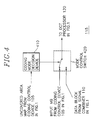
- FIG. 4 there is illustrated a more detailed block diagram of the coding mode control switch 115 of Fig. 1.
- the coding mode control switch 115 provides a two-dimensional DCT processor 120 shown in Fig. 1 with either a macroblock from the coding control device 105 or an output block from the signal combiner 110 according to the information contained in the uncovered map thereof from the coding control device 105 shown in Figs. 1 and 3. Specifically, when the macroblock under consideration within the current frame is determined to belong to an uncovered area(s) according to the information contained in the uncovered area map thereof, acknowledging the macroblock should be coded by the intra coding technique regardless of the coding mode decided in the signal combiner 110 for the macroblock, the coding mode control switch 115 provides the macroblock supplied from the coding control device 105.
- the coding mode control switch includes a coding mode decision device 410, and a mode control switch 420.
- the coding mode decision device 410 determines, by taking the uncovered area map as its input, whether the macroblock belongs to the uncovered area(s), by, e.g., counting the number of pixels within the macroblock, which belong to the uncovered area(s) in the uncovered map, and determining that the macroblock belongs to the uncovered area(s) when the counted number exceeds a predetermined value; and issues a switching control signal to the mode control switch 420 to select either the macroblock from the coding control device 105 when the macroblock belongs to the uncovered area(s), or the output block from the signal combiner 110, otherwise.
- an encoding apparatus for coding digital video signals describing a scene having at least one moving object and a stationary background, said digital video signals being represented by a series of video frames, each video frame being divided into a plurality of coding blocks, having a capability of adaptively selecting one of an intra coding technique and a non-intra coding technique to be applied to each coding block, which comprises:
- the encoder comprises a coding mode control device capable of accurately controlling the coding mode of each image data block in digital video signals.
Description
- The present invention is related to a digital video signal coding system according to the preamble of
claim 1. - In digital video signal coding applications such as high definition television, video conferencing system, video telephone and video door phone, video signals are transmitted in a digitized form. When the video signals comprising a sequence of video frames is expressed in a digitized form, there is bound to occur a substantial amount of digital data, for each line in a video frame is defined by a sequence of digital data elements referred to as "pixels". Since, however, the available frequency bandwidth of a conventional transmission channel is limited, in order to transmit the substantial amount of digital data through the channel, use of a video signal encoding apparatus may become necessary to compress or reduce the volume of the data to be transmitted.
- The digital video signal can be normally compressed without seriously affecting its integrity because there usually exist certain correlationships or redundancies among some of the pixels in a single frame and also among those of neighboring frames. Out of various video compression techniques, so-called hybrid coding techniques, together with statistical coding techniques, are known to be most effective.
- Most hybrid coding techniques employ an adaptive intra/non-intra coding, discrete cosine transform(DCT), quantization of transform coefficients, and VLC(variable length coding) as is well known in the art. An input video frame is divided into coding blocks, referred to as macroblocks, with each macroblock typically consisting of 16 x 16 pixels, and processed as such according to a given hybrid coding scheme. The adaptive intra/non-intra coding is a process of selecting video signals for a subsequent DCT process from either PCM(pulse code modulation) data of a current frame or motion compensated DPCM(differential pulse code modulation) data of a current frame adaptively, i.e., based on the variance thereof.
- The non-intra coding technique, which is based on the concept of reducing the redundancies between neighboring frames, is used to predict the current frame according to the motion flow of an object and produce difference signals, referred to as displaced frame difference(DFD) signals, representing the difference between the current frame and its prediction. Normally, the resultant coded data length of the DFD signals is shorter than that of the corresponding intra coding signals.
- A scene in a video signal may be divided into two portions: i.e., moving objects; and the stationary background which contains no moving objects. When an object moves within the background of the scene, however, there will be an area which used to be hidden behind the moved object but becomes visible after the moving. Logically, this newly appeared area(hereinafter referred to as "uncovered area") should be coded by using the intra coding technique (and not the non-intra coding method inasmuch as there is no similarity or redundancy relating to the newly appeared portion in the previous frame, which can be used to predict the current frame). Sometimes, however, it happens that the coding mode selecting process purely based on the variance may incorrectly choose the non-intra coding, instead of the intra coding, to encode the newly appeared area.
- The document D2: SIGNAL PROCESSING: IMAGE COMMUNICATION, vol. 4, no. 6, 1 November 1992, ELSEVIER, AMSTERDAM, NL pages 519-528, XP322093 J.S. KIM ET AL. 'Local Motion-Adaptive Interpolation Technique Based on Block Matching Algorithms' discloses a video signal encoding apparatus showing the features of the preamble of
claim 1. However, in order to calculate covered regions, uncovered regions, stationary regions and moving regions a rather complicated mathematical rule is applied which leads to a great computational effort for the video signal encoding apparatus. - Document US-A-4,689,671 discloses a video signal encoding apparatus having detecting means for detecting an uncovered background region. These detecting means calculate the difference between the current input signal and the one-frame signal of the immediately preceding frame as well as a difference between the current frame and its motion compensated predicted frame. The detecting means further produces a coding sequence out of the calculated differences and determines an uncovered region from this coding sequence. Again, the computational effort for detecting uncovered regions is very high since several different frames as well as motion compensated predicted frames have to be computed.
- It is, therefore, a primary object of the present invention to provide an encoder which can select the coding mode for a newly appeared portion with less computational burden.
The invention achieves this object with the subject-matter ofclaim 1. Preferred embodiments of the invention are described in the dependent claims. - The above and other objects and features of the present invention will become apparent from the following description of preferred embodiment given in conjunction with the accompanying drawings, in which;
- Fig. 1 depicts a block diagram of a video encoder in accordance with the preferred embodiment of the present invention;
- Fig. 2 illustrates a process for detecting an uncovered
area(s), performed by the
coding control device 105 shown in Fig. 1; - Fig. 3 presents a block diagram of an exemplary internal
structure of the
coding control device 105 shown in Fig. 1; and - Fig. 4 represents a block diagram of an exemplary internal
structure of the coding
mode control switch 115 shown in Fig. 1. -
- Referring to Fig. 1, there is illustrated a block diagram of a
video encoder 100 in accordance with the preferred embodiment of the present invention. - As shown in Fig. 1, input video signals comprising a sequence of video frames each of which is, in turn, divided into a plurality of macroblocks, is first fed, on a macroblock-by-macroblock basis, into the
video encoder 100 through acoding control device 105. Thecoding control device 105 then, when given three successive frames, i.e., a current frame and the previous and next frames in the input video signals, detects an uncovered area(s) within the current frame; provides an uncovered area map bearing such detected information for a codingmode control switch 115; and outputs the video signals of the current frame to amotion estimator 150, a signal combiner 110 and the codingmode control switch 115, as will be described more fully hereinbelow. - The
motion estimator 150, given the current and the previous frame stored in aframe store 160, predicts the current frame from the previous frame by way of generating a prediction result for each of the macroblocks within the current frame and providing the prediction result for amotion compensator 155. - The signal combiner 110 subtracts a predictive block calculated by the
motion compensator 155 based on the prediction result from themotion estimator 150, from each macroblock within the current frame; decides a coding, i.e., intra or non-intra coding, mode for each macroblock based on the variance thereof; and supplies as an output block either the original macroblock(PCM block) or the prediction error block(DPCM block) resulting from the subtraction, to the codingmode control device 115, depending on the decided coding mode. - The coding
mode control switch 115 then provides a two-dimensional DiscreteCosine Transformation processor 120 with either the macroblock supplied from thecoding control device 105 or the output block from the signal combiner 110 according to the information contained in the uncovered area map from thecoding control device 105. Specifically, when the macroblock under consideration within the current frame is determined to belong to an uncovered area(s) according to the information contained in the uncovered area map, acknowledging the macroblock should be coded by the intra coding technique, the codingmode control switch 115 provides the macroblock supplied from thecoding control device 105. Otherwise, i.e., when the macroblock does not belong to the uncovered area(s) in the current frame, the codingmode control switch 115 provides the output block from the signal combiner 110. In this case, therefore, the coding mode for the macroblock is maintained as is determined by the signal combiner 110 in a conventional manner. - Each resultant block from the coding
mode control switch 115 is then transformed into its spectral components via the two-dimensional DCT processor 120 and supplied via aquantizer 125 as quantized video block to avariable length encoder 130 and then to a transmission buffer(not shown). Also, the inversely quantized and transformed block via aninverse quantizer 135 and an inverse transformer 140 (,added to the predictive block from themotion compensator 155 in case the block has been coded by non-intra coding) are, for a next prediction, supplied to themotion compensator 155 and themotion estimator 150 via aframe memory 160 in the form of a candidate predictive block that is retarded by one frame interval from the current frame now present at anoutput 106 of thecoding control device 105. - Turning now to Fig. 2, there is illustrated an exemplary process performed by the
coding control device 105 of Fig. 1, for detecting an uncovered area(s) in the current frame of the input video signals. (As discussed above, an uncovered area denotes an area which used to be hidden behind a moving object but becomes visible after the moving.) - For the purpose of illustration, we will assume that a moving
object 200 has moved laterally from right to left between the previous and current frames, and also between the current and next frames as shown in Fig. 2, wherein reference symbols F(N-1), F(N) and F(N+1) denote the previous, current and next frames, respectively. Further, in Fig. 2, reference symbols A1 and A2 shall denote an uncovered area in the current frame F(N) after the movement of themoving object 200 between the previous and current frames F(N-1) and F(N), and an area covered in the next frame F(N+1) after the movement of anmoving object 200 between the current and next frames F(N) and F(N+1), respectively. - In order to detect an uncovered area(s) A2 present in the current, frame differences FD(N-1, N), FD(N, N+1), which have a logic-1 value in an area where there is a change between the two given frames, are obtained between the previous and current frames, and between the current and next frames, respectively, by using a method disclosed in, e.g., Matthias Bierling and Robert Thomas, "Motion Compensated Field Interpolation using Hierarchically Structured Displacement Estimation," Signal Processing 11, pp. 387-404 (1986), as shown in Fig. 2.
- The two Frame differences FD(N-1, N), FD(N, N+1) are then Exclusive-ORed to exclude the common area between the two frame differences FD(N-1, N) and FD(N, N+1), to thereby obtain two separate areas A1 and A2. Thereafter, to differentiate the uncovered area(s) A2 from the area(s) A1 covered in the next frame, the two separate areas A1 and A2 are ANDed with the frame differences FD(N-1, N), detecting the uncovered area(s) in the current frame F(N) as is required.
- Referring to Fig. 3, there is shown a more detailed block diagram of the
coding control device 105 shown in Fig. 1, wherein the above described uncovered area detecting process can be carried out. - As shown in Fig. 3, when input video signals (e.g., the video signals of the next frame F(N+1) in Fig. 2) is first fed into a
frame delay logic 305 and aframe difference calculator 310 as its one input, theframe delay logic 305 retards the input video signals by one frame interval and supplies the retarded input video signals (e.g., the video signals of the current frame F(N) in Fig. 2) to theframe difference calculator 310 as its another input. Theframe difference calculator 310 then performs the above-described frame difference calculation over its two inputs and transfers the resultant frame difference (e.g., the frame difference FD(N, N+1) in Fig. 2) to anotherframe delay logic 320 and an Exclusive-OR logic 330, respectively. Theframe delay logic 320 delays the calculated frame difference by one frame interval, and supplies the delayed frame difference (e.g., the frame difference FD(N-1, N) in Fig. 2) to the Exclusive-OR logic 330 and anAND logic 350. The Exclusive-OR logic 330 performs the Exclusive-OR operation over its two input and supplies the result (e.g., the signal XOR[FD(N-1, N), FD(N, N+1)] shown in Fig. 2)to theAND logic 350. TheAND logic 350 performs the AND operation over its two inputs to obtain an uncovered area map (e.g., the signal AND{FD[N-1,N], XOR[FD(N-1,N),FD(N,N+1)]} shown in Fig. 2) for the retarded input video signals (e.g., the current frame F(N) in Fig. 2), as is desired. - Referring now to Fig. 4, there is illustrated a more detailed block diagram of the coding
mode control switch 115 of Fig. 1. - As is described above, the coding
mode control switch 115 provides a two-dimensional DCT processor 120 shown in Fig. 1 with either a macroblock from thecoding control device 105 or an output block from the signal combiner 110 according to the information contained in the uncovered map thereof from thecoding control device 105 shown in Figs. 1 and 3. Specifically, when the macroblock under consideration within the current frame is determined to belong to an uncovered area(s) according to the information contained in the uncovered area map thereof, acknowledging the macroblock should be coded by the intra coding technique regardless of the coding mode decided in the signal combiner 110 for the macroblock, the codingmode control switch 115 provides the macroblock supplied from thecoding control device 105. - As shown in Fig. 4, the coding mode control switch includes a coding
mode decision device 410, and amode control switch 420. The codingmode decision device 410 determines, by taking the uncovered area map as its input, whether the macroblock belongs to the uncovered area(s), by, e.g., counting the number of pixels within the macroblock, which belong to the uncovered area(s) in the uncovered map, and determining that the macroblock belongs to the uncovered area(s) when the counted number exceeds a predetermined value; and issues a switching control signal to themode control switch 420 to select either the macroblock from thecoding control device 105 when the macroblock belongs to the uncovered area(s), or the output block from thesignal combiner 110, otherwise. - Summarising, an encoding apparatus is provided for coding digital video signals describing a scene having at least one moving object and a stationary background, said digital video signals being represented by a series of video frames, each video frame being divided into a plurality of coding blocks, having a capability of adaptively selecting one of an intra coding technique and a non-intra coding technique to be applied to each coding block, which comprises:
- uncovered area detecting means for, in responsive to a current frame and the previous and next frames thereof in the digital video signals, detecting an uncovered area representing a portion in the current frame, which used to be hidden behind the moving object in the previous frame but becomes visible after a movement of the moving object between the previous and current frames; and
- coding mode control means for determining, for each of the coding blocks in the current frame, whether said each of the coding blocks belongs to the uncovered area or not, and applying the intra coding technique to said each of the coding blocks regardless of the adaptively selected coding mode.
-
- Hence, the encoder comprises a coding mode control device capable of accurately controlling the coding mode of each image data block in digital video signals.
Claims (3)
- An apparatus (100) for encoding video signals describing a scene having at least one moving object (200) and a stationary background, the video signals being represented by a sequence of video frames (F(N-1),F(N),F(N+1)) including a previous (F(N-1)), a current (F(N)) and a next (F(N+1)) frame and each video frame (F(N-1);F(N);F(N+1)) being divided into a plurality of coding blocks, which comprises:characterised in, that:a) means (310) for determining a current frame difference (FD(N-1,N)) and a next frame difference (FD(N,N+1)), wherein the current frame difference (FD(N-1,N)) represents differences between the current (F(N)) and the previous (F(N-1)) frames and the next frame difference (FD(N,N+1)) denotes differences between the current (F(N)) and the next (F(N+1)) frames;b) means (330) for detecting a transition region (A1,A2) including a covered region (A1) and an uncovered region (A2), wherein the covered region (A1) is an area in the next frame (F(N+1)) which used to be visible in the current frame (F(N)) but is hidden behind the moving object (200) after a movement of the moving object (200) between the current (F(N)) and the next (F(N+1)) frames, and the uncovered region (A2) denotes an area in the current frame (F(N)) which used to be hidden behind the moving object (200) in the previous frame (F(N-1) but becomes visible after the movement of the moving object (200) between the previous (F(N-1) and the current (F(N)) frames; andthat the apparatus further comprisesc) the transition region detecting means (330) are designed to detect the transition regions by XORing the current frame difference (FD(N-1,N)) and the next frame difference (FD(N,N+1)); andc) means (350) for identifying the uncovered region (A2) as a common portion of the transition region (A1,A2) and the current frame difference (FD(N-1,N)).
- The apparatus of claim 1 further comprising:d) means (145,150,155,160) for producing a predictive block corresponding to each of the coding blocks in the current frame (F(N)) based on the previous (F(N-1)) and the current (F(N)) frames;e) means (115) for selecting, for said each of the coding blocks, either the predictive block or the corresponding coding block by checking whether said each of the coding blocks belongs to the uncovered region (A2) or not to thereby provide a resultant block; andf) means (120,125,130) for encoding the resultant block to thereby provide an encoded video signal.
- The apparatus of claim 2, wherein, if the coding block belongs to the uncovered region (A2), the coding block is selected to be encoded and, if otherwise, the predictive block is chosen.
Applications Claiming Priority (2)
| Application Number | Priority Date | Filing Date | Title |
|---|---|---|---|
| KR9316211 | 1993-08-20 | ||
| KR1019930016211A KR0128859B1 (en) | 1993-08-20 | 1993-08-20 | Adaptive image coding controller |
Publications (3)
| Publication Number | Publication Date |
|---|---|
| EP0639924A2 EP0639924A2 (en) | 1995-02-22 |
| EP0639924A3 EP0639924A3 (en) | 1995-04-05 |
| EP0639924B1 true EP0639924B1 (en) | 2000-01-12 |
Family
ID=19361654
Family Applications (1)
| Application Number | Title | Priority Date | Filing Date |
|---|---|---|---|
| EP19940113072 Expired - Lifetime EP0639924B1 (en) | 1993-08-20 | 1994-08-22 | Coding mode control device for digital video signal coding system |
Country Status (6)
| Country | Link |
|---|---|
| US (1) | US5528300A (en) |
| EP (1) | EP0639924B1 (en) |
| JP (1) | JP3717956B2 (en) |
| KR (1) | KR0128859B1 (en) |
| CN (1) | CN1066001C (en) |
| DE (1) | DE69422558D1 (en) |
Families Citing this family (8)
| Publication number | Priority date | Publication date | Assignee | Title |
|---|---|---|---|---|
| KR100211916B1 (en) * | 1995-10-26 | 1999-08-02 | 김영환 | Method for determination of coding type and mode in the object coding based on shape information |
| EP1689191A3 (en) * | 1996-11-07 | 2008-12-10 | Panasonic Corporation | Image encoder and image decoder |
| CA2365233C (en) * | 1999-12-28 | 2013-03-12 | Sony Corporation | Signal processing device and method, and recording medium |
| KR100446083B1 (en) * | 2002-01-02 | 2004-08-30 | 삼성전자주식회사 | Apparatus for motion estimation and mode decision and method thereof |
| CN1214649C (en) * | 2003-09-18 | 2005-08-10 | 中国科学院计算技术研究所 | Entropy encoding method for encoding video predictive residual error coefficient |
| CN101217663B (en) * | 2008-01-09 | 2010-09-08 | 上海华平信息技术股份有限公司 | A quick selecting method of the encode mode of image pixel block for the encoder |
| KR101299249B1 (en) | 2008-08-29 | 2013-08-22 | 삼성테크윈 주식회사 | Digital photographing apparatus, method for controlling the same, and recording medium storing program to implement the method |
| FR3120173A1 (en) * | 2021-02-19 | 2022-08-26 | Orange | Determining at least one picture encoding mode or at least one picture decoding mode, picture encoding and decoding using such determination |
Family Cites Families (13)
| Publication number | Priority date | Publication date | Assignee | Title |
|---|---|---|---|---|
| US3403226A (en) * | 1965-09-30 | 1968-09-24 | Bell Telephone Labor Inc | Reduced bandwidth dual mode encoding of video signals |
| JPS61114677A (en) * | 1984-11-09 | 1986-06-02 | Nec Corp | Adaptability prediction coding decoding system and device for animation signal |
| CA1282490C (en) * | 1985-06-27 | 1991-04-02 | Nec Corporation | Coding apparatus for moving object image |
| US4774570A (en) * | 1986-09-20 | 1988-09-27 | Sony Corporation | System for processing video signal for detecting changes in video data and security monitoring system utilizing the same |
| JPH082106B2 (en) * | 1986-11-10 | 1996-01-10 | 国際電信電話株式会社 | Hybrid coding method for moving image signals |
| US5040060A (en) * | 1987-12-01 | 1991-08-13 | Canon Kabushiki Kaisha | Image information transmission system with compression based on still-image redundancy |
| EP0330269B1 (en) * | 1988-02-23 | 1993-09-22 | Koninklijke Philips Electronics N.V. | Method of and device for estimating the extent of motion in a picture element of a television picture |
| JP2570384B2 (en) * | 1988-05-30 | 1997-01-08 | 日本電気株式会社 | Video signal encoding / decoding method |
| US5233629A (en) * | 1991-07-26 | 1993-08-03 | General Instrument Corporation | Method and apparatus for communicating digital data using trellis coded qam |
| JPH0564199A (en) * | 1991-08-29 | 1993-03-12 | Pioneer Electron Corp | Picture monitor |
| KR940011881B1 (en) * | 1991-12-23 | 1994-12-27 | 주식회사 금성사 | Apparatus for detecting moving picture |
| EP0561593B1 (en) * | 1992-03-17 | 1997-07-16 | Sony Corporation | Image compression apparatus |
| US5387938A (en) * | 1992-10-08 | 1995-02-07 | Matsushita Electric Industrial Co., Ltd. | Adaptive interframe/intraframe block coding method and apparatus |
-
1993
- 1993-08-20 KR KR1019930016211A patent/KR0128859B1/en not_active IP Right Cessation
-
1994
- 1994-08-20 CN CN94116856A patent/CN1066001C/en not_active Expired - Lifetime
- 1994-08-22 DE DE69422558T patent/DE69422558D1/en not_active Expired - Lifetime
- 1994-08-22 EP EP19940113072 patent/EP0639924B1/en not_active Expired - Lifetime
- 1994-08-22 US US08/294,530 patent/US5528300A/en not_active Expired - Lifetime
- 1994-08-22 JP JP19694594A patent/JP3717956B2/en not_active Expired - Lifetime
Also Published As
| Publication number | Publication date |
|---|---|
| EP0639924A2 (en) | 1995-02-22 |
| KR0128859B1 (en) | 1998-04-10 |
| JPH07154782A (en) | 1995-06-16 |
| CN1066001C (en) | 2001-05-16 |
| EP0639924A3 (en) | 1995-04-05 |
| DE69422558D1 (en) | 2000-02-17 |
| JP3717956B2 (en) | 2005-11-16 |
| US5528300A (en) | 1996-06-18 |
| KR950007522A (en) | 1995-03-21 |
| CN1111884A (en) | 1995-11-15 |
Similar Documents
| Publication | Publication Date | Title |
|---|---|---|
| US5859668A (en) | Prediction mode selecting device in moving image coder | |
| KR0168458B1 (en) | Distorting deminishing method and apparatus | |
| US5434622A (en) | Image signal encoding apparatus using adaptive frame/field format compression | |
| KR100209793B1 (en) | Apparatus for encoding/decoding a video signals by using feature point based motion estimation | |
| KR100291493B1 (en) | Moving vector processing device for video signal compression | |
| CA2070757C (en) | Motion compensated predicting apparatus | |
| EP0680217B1 (en) | Video signal decoding apparatus capable of reducing blocking effects | |
| JP2911682B2 (en) | Motion compensation using the minimum number of bits per motion block as a criterion for block matching | |
| KR20000053028A (en) | Prediction method and device with motion compensation | |
| KR0178195B1 (en) | Apparatus for encoding an image signal using vector quantization technique | |
| JPH08265765A (en) | Image coding system and motion compensating device for use therein | |
| US5689312A (en) | Block matching motion estimation method | |
| EP0639924B1 (en) | Coding mode control device for digital video signal coding system | |
| JP3950211B2 (en) | Motion vector encoding device | |
| KR100240620B1 (en) | Method and apparatus to form symmetric search windows for bidirectional half pel motion estimation | |
| KR0181067B1 (en) | Moving picture encoder of having compatibility | |
| KR0174441B1 (en) | Full motion image encoder by using adaptive motion compensation | |
| KR100207419B1 (en) | Method and apparatus for controlling generation of bit rate in video encoding | |
| KR100203638B1 (en) | Method for estimating motion using half-pixel by half-pixel | |
| KR100207391B1 (en) | Image coding system and moving information detecting method using adaptive vector quantization | |
| KR100207418B1 (en) | Method and apparatus for controlling generation of bit rate in video encoding | |
| KR20010041441A (en) | Method and device for encoding a video signal | |
| JPH0818952A (en) | Image signal coder | |
| KR0124162B1 (en) | Prediction coding method | |
| KR0178197B1 (en) | Apparatus for encoding an image signal using region segmentation |
Legal Events
| Date | Code | Title | Description |
|---|---|---|---|
| PUAI | Public reference made under article 153(3) epc to a published international application that has entered the european phase |
Free format text: ORIGINAL CODE: 0009012 |
|
| PUAL | Search report despatched |
Free format text: ORIGINAL CODE: 0009013 |
|
| AK | Designated contracting states |
Kind code of ref document: A2 Designated state(s): DE FR GB NL |
|
| AK | Designated contracting states |
Kind code of ref document: A3 Designated state(s): DE FR GB NL |
|
| 17P | Request for examination filed |
Effective date: 19951004 |
|
| 17Q | First examination report despatched |
Effective date: 19971031 |
|
| GRAG | Despatch of communication of intention to grant |
Free format text: ORIGINAL CODE: EPIDOS AGRA |
|
| GRAG | Despatch of communication of intention to grant |
Free format text: ORIGINAL CODE: EPIDOS AGRA |
|
| GRAG | Despatch of communication of intention to grant |
Free format text: ORIGINAL CODE: EPIDOS AGRA |
|
| GRAH | Despatch of communication of intention to grant a patent |
Free format text: ORIGINAL CODE: EPIDOS IGRA |
|
| GRAH | Despatch of communication of intention to grant a patent |
Free format text: ORIGINAL CODE: EPIDOS IGRA |
|
| GRAA | (expected) grant |
Free format text: ORIGINAL CODE: 0009210 |
|
| AK | Designated contracting states |
Kind code of ref document: B1 Designated state(s): DE FR GB NL |
|
| PG25 | Lapsed in a contracting state [announced via postgrant information from national office to epo] |
Ref country code: NL Free format text: LAPSE BECAUSE OF FAILURE TO SUBMIT A TRANSLATION OF THE DESCRIPTION OR TO PAY THE FEE WITHIN THE PRESCRIBED TIME-LIMIT Effective date: 20000112 Ref country code: FR Free format text: LAPSE BECAUSE OF FAILURE TO SUBMIT A TRANSLATION OF THE DESCRIPTION OR TO PAY THE FEE WITHIN THE PRESCRIBED TIME-LIMIT Effective date: 20000112 |
|
| REF | Corresponds to: |
Ref document number: 69422558 Country of ref document: DE Date of ref document: 20000217 |
|
| PG25 | Lapsed in a contracting state [announced via postgrant information from national office to epo] |
Ref country code: DE Free format text: LAPSE BECAUSE OF FAILURE TO SUBMIT A TRANSLATION OF THE DESCRIPTION OR TO PAY THE FEE WITHIN THE PRESCRIBED TIME-LIMIT Effective date: 20000413 |
|
| NLV1 | Nl: lapsed or annulled due to failure to fulfill the requirements of art. 29p and 29m of the patents act | ||
| EN | Fr: translation not filed | ||
| PLBE | No opposition filed within time limit |
Free format text: ORIGINAL CODE: 0009261 |
|
| STAA | Information on the status of an ep patent application or granted ep patent |
Free format text: STATUS: NO OPPOSITION FILED WITHIN TIME LIMIT |
|
| 26N | No opposition filed | ||
| REG | Reference to a national code |
Ref country code: GB Ref legal event code: IF02 |
|
| REG | Reference to a national code |
Ref country code: GB Ref legal event code: 732E |
|
| REG | Reference to a national code |
Ref country code: GB Ref legal event code: 732E Free format text: REGISTERED BETWEEN 20130404 AND 20130410 |
|
| PGFP | Annual fee paid to national office [announced via postgrant information from national office to epo] |
Ref country code: GB Payment date: 20130821 Year of fee payment: 20 |
|
| REG | Reference to a national code |
Ref country code: GB Ref legal event code: PE20 Expiry date: 20140821 |
|
| PG25 | Lapsed in a contracting state [announced via postgrant information from national office to epo] |
Ref country code: GB Free format text: LAPSE BECAUSE OF EXPIRATION OF PROTECTION Effective date: 20140821 |