EP0639004B1 - Digital time delay apparatus and method - Google Patents
Digital time delay apparatus and method Download PDFInfo
- Publication number
- EP0639004B1 EP0639004B1 EP94305012A EP94305012A EP0639004B1 EP 0639004 B1 EP0639004 B1 EP 0639004B1 EP 94305012 A EP94305012 A EP 94305012A EP 94305012 A EP94305012 A EP 94305012A EP 0639004 B1 EP0639004 B1 EP 0639004B1
- Authority
- EP
- European Patent Office
- Prior art keywords
- tap
- window
- address
- output
- phase
- Prior art date
- Legal status (The legal status is an assumption and is not a legal conclusion. Google has not performed a legal analysis and makes no representation as to the accuracy of the status listed.)
- Expired - Lifetime
Links
Images


Classifications
-
- H—ELECTRICITY
- H04—ELECTRIC COMMUNICATION TECHNIQUE
- H04L—TRANSMISSION OF DIGITAL INFORMATION, e.g. TELEGRAPHIC COMMUNICATION
- H04L7/00—Arrangements for synchronising receiver with transmitter
- H04L7/04—Speed or phase control by synchronisation signals
-
- H—ELECTRICITY
- H03—ELECTRONIC CIRCUITRY
- H03K—PULSE TECHNIQUE
- H03K5/00—Manipulating of pulses not covered by one of the other main groups of this subclass
- H03K5/13—Arrangements having a single output and transforming input signals into pulses delivered at desired time intervals
- H03K5/135—Arrangements having a single output and transforming input signals into pulses delivered at desired time intervals by the use of time reference signals, e.g. clock signals
-
- H—ELECTRICITY
- H03—ELECTRONIC CIRCUITRY
- H03K—PULSE TECHNIQUE
- H03K5/00—Manipulating of pulses not covered by one of the other main groups of this subclass
- H03K5/13—Arrangements having a single output and transforming input signals into pulses delivered at desired time intervals
- H03K5/131—Digitally controlled
-
- H—ELECTRICITY
- H04—ELECTRIC COMMUNICATION TECHNIQUE
- H04L—TRANSMISSION OF DIGITAL INFORMATION, e.g. TELEGRAPHIC COMMUNICATION
- H04L7/00—Arrangements for synchronising receiver with transmitter
- H04L7/0016—Arrangements for synchronising receiver with transmitter correction of synchronization errors
- H04L7/0033—Correction by delay
-
- H—ELECTRICITY
- H04—ELECTRIC COMMUNICATION TECHNIQUE
- H04L—TRANSMISSION OF DIGITAL INFORMATION, e.g. TELEGRAPHIC COMMUNICATION
- H04L7/00—Arrangements for synchronising receiver with transmitter
- H04L7/0054—Detection of the synchronisation error by features other than the received signal transition
- H04L7/0058—Detection of the synchronisation error by features other than the received signal transition detection of error based on equalizer tap values
Definitions
- This invention relates to digital circuit time delay elements, such as calibration methods and apparatus for such time delays.
- the clock rate of a controlled oscillator or the time delay value of a delay element can be obtained by applying an analog voltage or current as the control signal to its voltage controlled oscillator locked to a reference oscillator.
- This control signal is often a filtered or smoothed output from a phase detector, frequency range controller, a timing detection circuit, or a combined control signal from several detectors.
- control signal enables a continuous, step-less tuning of the controlled frequency or time delay value, however, the high loop gain due to high frequency or high data rate operations, makes the operation very sensitive to noise. Performance optimization becomes difficult especially when integration with very large scale high speed digital functions is necessary, since digital switching operations tends to induce a large amount of switching noise.
- An all-digital phase locked loop based on use of time delay elements, can eliminate these concerns.
- time delay values can be obtained having a "resolution" determined by the delay value of the individual element.
- the delay element could be a standard integrated circuit inverter device.
- the delay of the inverters are not fixed and will be variable due to process variations, temperature change, and power supply noise. Therefore, where a constant, accurate delay is required, such as in most of the precise applications mentioned above, the standard inverter is not adequate.
- CMOS and other processing technologies provide more density of devices, long strings of cascaded inverters of small delay can be obtained at lower and lower cost and the inverters can be used as the basic high resolution unit delay element.
- all-digital solutions are becoming attractive to replace many more applications which are implemented now in analog technique or mixed analog-digital schemes.
- a circuit for calibrating the propagation delay of serially-connected time delay elements is known from DE-A-4 104 329 (GB 2 241 620 A). This discloses a circuit wherein a reference clock is applied to the delay line and delayed versions of the clock obtained from taps along the delay line are used to clock a plurality of flip-flops, the data inputs of which are the undelayed clock. With up to 180° phase delay a logical "1" is clocked to the flip-flops' outputs; further down the delay line, beyond 180° phase delay a logical "0" is clocked to their outputs. This allows the number of time delay elements required to provide 180° phase delay to be determined and made available.
- Another provision of the invention is an all digital scheme which employs only standard logic cells such that the function can be easily integrated into a digital design which can be designed and verified with standard logic verification tools.
- an all-digital real time delay detection and digital representation scheme for on-chip delay regulation of integrated circuits.
- the detection scheme primarily comprises: a delay line formed by cascaded unit delay cells from which phase shifted copies of a crystal reference clock are obtained; a phase comparator array formed by an array of simple exclusive OR (XOR) gates for phase comparison between each of the phase shifted copy and the original reference clock; a delta-phase window generation circuit which produces a "window" region consisting of several stages centered at the stage of the delay line where the reference clock is delayed by a time lapse which equals the reference clock period; and a delta-phase window detection block which detects the "address" of the two end locations of the delta-phase window region.
- XOR simple exclusive OR
- delta-phase window region refers to the stages in the delay line from which the delayed or phase shifted copy of the crystal reference clock has a small phase difference with the original reference clock.
- a number representative of the average position of the window center is obtained.
- the two detected end address are added and the sum is divided by two to generate the address of the window center, or the zero-phase-address.
- This address or value represents the number of stages needed to delay the time lapse equal to the cycle or period time of the reference clock and will be accurate for all operating conditions.
- the window center address or the number of stages required are different for integrated circuits from different processing runs, and will vary during circuit operation due to temperature variation, power supply fluctuation and other noise sources which cause delay fluctuation of the unit delay cells.
- the output of the scheme is a digital number which can be used as the delay regulation information for other parts of any circuits on the same die.
- N is the number of unit delay cells required for delaying the time lapse equals to the period T of a reference clock running at frequency F
- n unit delay cells could be used to delay a different time t.
- the oscillating frequency would be F multiplied by N/n, where N/n should be a positive number greater than one.
- time scaling operations can be performed through a decoding circuit or a read only memory (ROM) in which scaling information is stored.
- ROM read only memory
- Fig. 1 illustrates, in block diagram form, an embodiment for performing the delay detection in an integrated circuit in accordance with the present invention.
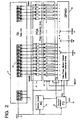
- Fig. 2 is a block diagram with certain details showing the delay line, the phase comparator array, and the formation of the delta-phase window.
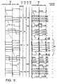
- Fig. 3 is a timing diagram illustrating the phase-shifted reference clock from the outputs of different unit delay stages of the delay line, and the resulted signal waveform from the outputs of the XOR gates of the phase comparator array.
- Fig. 4 is the timing diagram illustrating the zero phase address detection process.
- Fig. 5 shows a logic implementation of the zero phase address detection control block.
- Fig. 6 is a particular implementation of the update control logic.
- the Local Clock 10 (LCLK) is the input signal to the calibrator 1.
- This reference signal is the basic timing reference for the operation.
- the output of the address detector 1 is a digital word ZPA(n:0) 199 indicating the delay information in real time.
- the Delay Line (DL) II is seen to be constructed from a cascaded array of n unit delay cells 13, each of the unit delay cells is designated by an "address" corresponding to its physical location in the array.
- the unit delay cell of the first stage in DL has the address of "1”
- cell of the last stage n has the address of EADDR (end address).
- the stage from which the phase comparator array 21 (PCA) starts to do the phase comparison has the address of BADDR (begin address).
- BADDR and EADDR relates to the delay value of the unit delay cell which is Tud and the reference clock has a period of Tref.
- the detection envisions use of a range of possible unit delays where the delay is close to 360 degrees, i.e., which is called a window. Accordingly, the delay line should have adequate number of unit delay cells to accommodate all possible delays adding simultaneously.
- the phase comparator array (PCA) 21 consists of a plurality of XOR gates equal to EADDR - BADDR, where each gate receives the reference clock LCLK 10 as one input, and one of the outputs from the unit delay stages in the window of DL 11 as the other input.
- the XOR's are the phase comparator of the reference clock LCLK and its phase shifted copies.
- circuits of other logic gates, OR, NOR, AND, NAND with inverters can be combined to provide the same function as the exclusive OR (XOR).
- the outputs from PCA 21 are each applied to a clock input of a counter in the delta phase window generator (DPWG) 31, the outputs of which counters are directed to the inputs of the delta-phase window detector (DPWD) 41 which is essentially a parallel-in serial-out shifter.
- DPWD 41 samples the outputs of DPWG 31, and the pattern of "111...1100...0011...111" is expected as will be further explained with reference to Fig. 3.
- the stages in which the PCA output is zero are the "delta phase" addresses which means that the phase differences of the original LCLK and its delayed copy detected in these stages are in the neighborhood of zero.
- the address of the left side border of the "zero zone" indicated by an 1 -> 0 transition is called delta phase window low address (DPWLA) 43, while the right side border of the zero zone indicated by a 0 -> 1 transition is called delta phase window high address (DPWHA) 44.
- the center of this window region will be designated as the stage location where the reference clock is delayed exactly a full cycle such that the LCLK and its delayed copy have no phase difference.
- the address of the center stage is the so-called zero phase address (ZPA) 46.
- the detection of ZPA based on the detection of DPWLA and DPWHA is accomplished as follows: after the window pattern is sampled or parallel loaded into the shifter DPWD, the window data pattern is shifted left into a transition detector (TD) 61 while the synchronized address counter (AC) 51 starts counting the shift clock.
- TD transition detector
- AC synchronized address counter
- a pulse is output at TDO 63 which causes the zero phase address detection control (ZPADC) 91 to generate a signal LDL to latch the content of the address counter AC as the low address of the window into the window low address register (WLAREG) 71.
- ZPADC zero phase address detection control
- a pulse is again output of TDO 63 which causes the zero phase address detection control (ZPADC) 91 to generate a signal LDH to latch the content of the address counter AC as the high address of the window into the window high address register (WHAREG) 72.
- the two addresses are added in ZPAGEN 81 which is an (n+2) bit parallel adder.
- a simple shift operation of ZPAGEN performs the divide by 2 function. (The divide function is not actually necessary because the sum is representative of the coverage multiplied by a constant.) The result is a (n + 1) bit binary number ZPAG(n:0) which represents the window center location or the zero phase address in the delay line 11 at that instant.
- This ZPAG data 83 is then latched into a temporary register (TAREG) 75 by control signal LDT 93 from ZPADC 91.
- an update control block (UPDC) 101 to perform additional noise rejection by comparing the contents of TAREG and TBREG to find if the change in ZPAG value represents a steady delay shift or just a temporary fluctuation due to circuit noise.
- the data is loaded into the output register (ZPAREG) 78.
- the timing diagrams illustrate the delta phase window formation process.
- the column of output waveforms 201 are illustrative of the waveform output from the delay lines, each of which is delayed or phase shifted from the preceding one by the amount of the unit delay.
- Column 210 shows the phase difference of the corresponding waveforms in respect to the reference clock LCLK. Noting that at 360 degree phase shift, the waveform exactly coincides with LCLK.
- column 215 delta phase difference for the corresponding delayed waveforms in each stage in respect to the waveform which has a 360 degree phase difference with LCLK is shown in degrees.
- Column 220 shows the delta phase in percentage.
- the output waveforms from each taped stage of the delay line between BADDR and EADDR are phase compared with LCLK by the XOR gates in the PCA 21.
- the resulting waveforms of this logic function shown in the group of waveform near 250 stays low. Near the average the waveforms have the minimum pulse energy. Going either directions, the pulse is widen by a step wider than the pulse of 250. For high speed data rate operations, this step or the unit delay should be very small - less than a few hundred picoseconds.
- the output pulse width from the stages in the neighborhood of ZPA 250 will not be well defined due to noise, temperature or supply voltage fluctuations, making the distinction of the minimum pulse width or the zero phase difference location difficult.
- delta phase window This is a window region or a group of waveforms and we determine its center and assume that the center is the zero phase location.
- the outputs from the XOR's of the PCA 21 are used as trigger signals for the counters in the delta phase window generator DPWG 31.
- counters require a minimum clock pulse width to be reliably triggered.
- high speed counters are required.
- the counters used in DPWG 31 do not require high sensitivity to the triggered signals having a pre-defined minimum clock pulse width nor does the clock pulse width need to be constant or stable over all operation conditions.
- the status of a k-bit counter is defined as a "1” or as “full” if the counter has been triggered 2**k times and all the outputs are "1", after initial reset of zero.
- the status of a k-bit counter is defined as a "0" if it is not full.
- the counters clocked by the pulses corresponding to waveform 239 through 259 will not be triggered because of their inadequate pulse width, resulted in a "zero zone” of the counter status, or the so-called “delta phase window” region as mentioned before.
- the "width" of the delta phase window or the number of stages in this "zero zone” relates to the triggering sensitivity of the counter and to the pulse width of the trigger signal.
- the trigger signal width is related to the delay of the unit delay cells as well as to the speed of the XOR's and is subject to processing variations and changes in operating conditions. However, the differential or center of this "zero zone" is insensitive to all these conditions.
- the counters should not be too sensitive, i.e., trigger level pulse width must be no less than the time of several unit delays. Ideally, waveforms from the XOR's in PCA 21 are all well defined as shown in Fig. 3 and the counters in DPWG 31 could be reduced to 1-bit or simply to a T flip-flop.
- the waveforms 240 in Fig. 3, especially those in or near the "zero zone”, may not be as ideal as depicted in the Figure.
- These stages may have indeterminate states due to: (1) the generated window pattern contains "noise”, such as an "0" within the non-zero zone on the lower address side of the window; (2) counters not belonging to the zero zone miss some counts; (3) wrong ZPAG data being generated.
- Various noise rejection schemes can be employed to reduce the noise conditions.
- the noise condition 1) can be filtered out by using an increased number of k bits (k>1) for the counter, such that random triggering may increment a few counts, but will not make the counter full.
- a faulty window low address DPWLA
- This switching could be used as a noise status indicator in the zero phase address detection control block (ZPADC) 91 such that the fault detection precludes issuance of a new ZPAG data 83.
- ZPADC zero phase address detection control block
- an integrator/filter can be included for the update control (UPDC) function 101 which compares the new ZPAG value in TAREG 75 with the old value in TBREG 76, and updates the output ZPA in ZPAREG 78 only if the two ZPAG values are consistent for a preset number of cycles.
- Fig. 4 provides the timing diagram for the entire zero phase address (ZPA) detection apparatus and process.
- the reference clock LCLK 10 is the system clock.
- the counters in DPWG 31 are all reset to zero. All the DPWG outputs are then zeros and an output pattern of "0000...000..000" results.
- pulses with different width for each window address are generated from the XOR's and are used to clock the counters.
- the "window" pattern i.e., the counter status data in DPWG 31, is parallel-loaded into the delta phase window detection block (DPWD) 41 by the load window command LDWD 33.
- the LDWD 33 is provided by DPWG 31 to also reset the address counter AC 51 to the beginning address value (BADDR) of the detection region.
- a rising edge of the "detection window" command DETWD 43 starts the left shifting of the window pattern to the transition detect (TD) 61.
- the address counter AC counts the LCLK synchronously.
- transition 620 is detected in transition detector 61 and a pulse 630 is provided at TDO 63, which signals the ZPA detection control (ZPADC) 91 to send a load command pulse LDL 710 to latch the content (100 in the example) of the address counter (AC) 51, that is the address for the left-side end of the zero zone of the "window” into window low address register WLAREG 71.
- the window data pattern is continued to be left-shifted every LCLK until the 0 -> 1 transition 621 is detected, for which a pulse 631 at TDO is generated.
- the ZPADC will send a command pulse 720 at LDH to latch the address value (120) of the right-side end of the window into the window high address register (WHAREG) 72.
- the output of the full adder in ZPAGEN 81 which has added the address in WLAREG and WHAREG and divided the sum by two, provides an output ZPA value of 110 which is valid and is latched into TAREG 75 by the command pulse 930 at LDT.
- the ZPA data which was in TAREG (TA(n:0)) is moved to TBREG 76.
- TB(n:0) was 111 before the load command, there is no change in value.
- an update command pulse 103 at UPDZPA (not shown in this timing diagram) is issued and the ZPA value of 110 becomes available at the ZPA output.
- Fig. 5 shows an implementation example of the zero phase address detection control (ZPADC) block.
- ZPADC zero phase address detection control
- a READY Signal at the output of flip-flop 954 goes high and resets the counters in DPWG for the next-run window detection, as well as to signal the DPWD to end shifting.
- a load temporary register signal (LDT) is generated at the output of flip-flop 955, followed by an update clock UPDCK from 956.
- a clear or reset signal at 941 from the STARTUP block resets all the flip-flops and make it ready for another ZPA detection cycle.
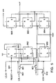
- Fig. 6 is a schematic of the update control block 101.
- An active low CLR signal on line 814 resets D flip-flop (DFF) 821 and 822. It also resets the RS latch formed by NAND gate 841 and 842, and output UPDZPR becomes “0". After reset, line 814 returns to "1", so both NOR gate 813 and NAND gate 842 are enabled.
- XOR 811 and 812 compare the LSB (least-significant-bit) and the next-to-LSB bit of TA(n:0) and TB(n:0) from TAREG 75 and TBREG 74 respectively. TA (n:0) and TB(n:0) represent two consecutive detected ZPAs.
- the invention provides a novel and advantageous apparatus and method for calibration of a digital delay line and for providing an accurate and precise reference for digital phase shifting applications which are compensated for varying process and temperature parameters.
Landscapes
- Physics & Mathematics (AREA)
- Nonlinear Science (AREA)
- Engineering & Computer Science (AREA)
- Computer Networks & Wireless Communication (AREA)
- Signal Processing (AREA)
- Pulse Circuits (AREA)
- Stabilization Of Oscillater, Synchronisation, Frequency Synthesizers (AREA)
Description
Claims (18)
- A method for periodically providing a signal which is accurately representative of propagation delay in an integrated circuit comprising:characterised in thatlaunching a reference clock signal into a serially connected chain of unit delay cells (11);providing taps at the outputs of a plurality of said serially connected unit delay cells;comparing the phase of signals at said plurality of output taps to the phase of said reference clock signal;
the method includes identifying on a periodic basis the zero tap, said zero tap being the tap at which a change of logic level of the output signal is closest to being in phase with a change of logic level of said reference clock signal, by establishing a window region and determining the zero tap position by establishing the average tap position between the two border taps of said window. - The method of claim 1 wherein the method for comparing the phase of signals at said plurality of output taps to the phase of said reference clock signal includes comparing the logic levels of said output signals and said reference clock signal.
- The method of claim 2 wherein the method for comparing the phase of signals at said plurality of output taps to the phase of said reference clock signal further includes periodically sampling and holding a binary representation of the result of said comparison of the logic levels of said output signals and said reference clock signal.
- The method of claim 3 wherein the method for comparing includes operating on said output signals and said reference clock signal with XOR means.
- The method of claim 4 wherein said comparing step is repeated periodically at a rate which is fast enough to compensate for ambient temperature and power supply variations which induce propagation delay changes in said integrated circuit and to maintain precision.
- The method of claim 5 wherein the step of establishing the average tap number is obtained by adding the tap number at the low border of said window to the tap number at the high border of said window, and dividing said sum by two.
- Apparatus for providing a signal which is accurately representative of propagation delay in an integrated circuit comprising:characterised in that the apparatus further includes means to identify on a periodic basis the zero tap, said zero tap being the tap at which a change of logic level of the output signal is closest to being in phase with a change of logic level of said reference clock signal, comprising means (21,31,41,51,61,81) to establish a window region and determine the zero tap position by establishing the average tap position between the two border taps of said window.an input terminal, said input terminal for receiving a clock reference signal (10);a serially connected chain of unit delay cells (13) including a first unit delay cell, said first unit delay cell being connected to said input terminal to launch said clock reference signal (10) for propagation down said chain of unit delay cells, each cell having an input and an output;a plurality of taps, each tap being connected to a said unit delay cell, said tap providing a signal representative of said delay cell output;
- The apparatus of claim 7 wherein said means to identify said zero tap comprises a phase comparator array (21) providing a plurality of output signals, means (31) to periodically sample and hold a binary representation of said output signals and provide a plurality of outputs,means (41,51,61) to analyse said sample and hold means output and to determine an address of a tap where said output values change from 1 to 0, this being the window low address (43) and an address of a tap where said output values change from 0 to 1, this being the window high address (44) andmeans (81) for determining a zero tap address by averaging said window low address and said window high address.
- The apparatus of claim 8 wherein said phase comparator array (21) comprises a plurality of logic level comparator means for comparing logic levels of said propagating clock signal to said reference clock signal.
- The apparatus of claim 9 wherein said logic level comparator means comprises XOR means.
- The apparatus of claim 10 wherein each said XOR means is connected to a corresponding tap and to said input terminal for receiving said clock reference signal (10)
- The apparatus as claimed in claim 10 or claim 11 wherein said XOR means have transient output pulses which have energy, and wherein said energy, in the ouput pulses of the XOR circuits having addresses between said window low address (43) and said window high address (44), is too low to cause said sample and hold means (31) outputs to register a logic 1 state.
- The apparatus as claimed in any one of claims 7 to 12 wherein said zero tap identifying means includes means to provide a digital signal representative of the physical position of said tap which is said zero tap.
- The apparatus as claimed in any one of claims 8 to 13 wherein said sample and hold means (31) has substantially identical threshold response to falling signals and to rising signals so that a threshold change which lowers the said window low address will have a matching increase in said window high address so that said average address is substantially unchanged as a function of threshold changes.
- The apparatus as claimed in any one of claims 7 to 14 wherein said zero tap identifying means includes means (101) for periodically updating said zero tap address, said periodic updating means including means for filtering whereby new address values must be consistent with an arbitrary number of previous addresses.
- The apparatus as claimed in any one of claims 7 to 15 wherein said zero tap identifying means includes,means for shifting serially (41);a counter (51), said counter being connected to a clock signal;means for parallel loading said sample and hold means outputs into said means for shifting serially, anda transition detector (61), said transition detector being connected to said means for shifting, whereby in operation, said transition detector provides and output indication of the occurrence of transitions 0 to 1 and 1 to 0; andmeans (91,71,72) responsive to said transition detector output signals for sampling said counter to provide said window low address and said window high address.
- The apparatus as claimed in any one of claims 8 to 16 wherein said sample and hold means (31) includes, a plurality of counter means, said counter means including a plurality of flip-flop circuits connected as a binary up counter, each said counter having an input and an output, said counter input being connected to one said phase comparator output.
- The apparatus of claim 17 wherein the number of flip-flops in said counter is large enough to provide a filtering so that a few noise triggers will not fill the counter.
Applications Claiming Priority (2)
| Application Number | Priority Date | Filing Date | Title |
|---|---|---|---|
| US105079 | 1993-08-11 | ||
| US08/105,079 US5457719A (en) | 1993-08-11 | 1993-08-11 | All digital on-the-fly time delay calibrator |
Publications (2)
| Publication Number | Publication Date |
|---|---|
| EP0639004A1 EP0639004A1 (en) | 1995-02-15 |
| EP0639004B1 true EP0639004B1 (en) | 1998-03-04 |
Family
ID=22303935
Family Applications (1)
| Application Number | Title | Priority Date | Filing Date |
|---|---|---|---|
| EP94305012A Expired - Lifetime EP0639004B1 (en) | 1993-08-11 | 1994-07-07 | Digital time delay apparatus and method |
Country Status (6)
| Country | Link |
|---|---|
| US (1) | US5457719A (en) |
| EP (1) | EP0639004B1 (en) |
| JP (1) | JPH07154245A (en) |
| KR (1) | KR950007336A (en) |
| DE (1) | DE69408749T2 (en) |
| TW (1) | TW230856B (en) |
Families Citing this family (58)
| Publication number | Priority date | Publication date | Assignee | Title |
|---|---|---|---|---|
| US6463396B1 (en) | 1994-05-31 | 2002-10-08 | Kabushiki Kaisha Toshiba | Apparatus for controlling internal heat generating circuit |
| US6064707A (en) * | 1995-12-22 | 2000-05-16 | Zilog, Inc. | Apparatus and method for data synchronizing and tracking |
| US6044122A (en) * | 1997-01-23 | 2000-03-28 | Ericsson, Inc. | Digital phase acquisition with delay locked loop |
| JPH10325887A (en) * | 1997-03-28 | 1998-12-08 | Seiko Instr Inc | Logic emergency circuit |
| US5886539A (en) * | 1997-04-10 | 1999-03-23 | Advanced Micro Devices, Ind | Communication within an integrated circuit by data serialization through a metal plane |
| US5774403A (en) * | 1997-06-12 | 1998-06-30 | Hewlett-Packard | PVT self aligning internal delay line and method of operation |
| US5903521A (en) * | 1997-07-11 | 1999-05-11 | Advanced Micro Devices, Inc. | Floating point timer |
| US6122278A (en) * | 1997-08-07 | 2000-09-19 | Advanced Micro Devices, Inc. | Circuit and method for protocol header decoding and packet routing |
| US5890100A (en) * | 1997-08-19 | 1999-03-30 | Advanced Micro Devices, Inc. | Chip temperature monitor using delay lines |
| US5943206A (en) * | 1997-08-19 | 1999-08-24 | Advanced Micro Devices, Inc. | Chip temperature protection using delay lines |
| FR2768575B1 (en) * | 1997-09-12 | 2004-04-09 | Sgs Thomson Microelectronics | METHOD FOR MEASURING TIME DELAY AND CIRCUIT IMPLEMENTING THE METHOD |
| US6192069B1 (en) | 1997-11-03 | 2001-02-20 | Advanced Micro Devices, Inc. | Circuit and methodology for transferring signals between semiconductor devices |
| US6031473A (en) * | 1997-11-17 | 2000-02-29 | Advanced Micro Devices, Inc. | Digital communications using serialized delay line |
| US5852616A (en) * | 1997-11-17 | 1998-12-22 | Advanced Micro Devices, Inc. | On-chip operating condition recorder |
| US6084933A (en) * | 1997-11-17 | 2000-07-04 | Advanced Micro Devices, Inc. | Chip operating conditions compensated clock generation |
| US5942937A (en) * | 1997-11-19 | 1999-08-24 | Advanced Micro Devices, Inc. | Signal detection circuit using a plurality of delay stages with edge detection logic |
| US6163759A (en) * | 1997-11-21 | 2000-12-19 | Advantest Corporation | Method for calibrating variable delay circuit and a variable delay circuit using the same |
| US6091348A (en) * | 1997-12-18 | 2000-07-18 | Advanced Micro Devices, Inc. | Circuit and method for on-the-fly bit detection and substitution |
| US6178208B1 (en) | 1997-12-18 | 2001-01-23 | Legerity | System for recovery of digital data from amplitude and phase modulated line signals using delay lines |
| US6046620A (en) * | 1997-12-18 | 2000-04-04 | Advanced Micro Devices, Inc. | Programmable delay line |
| US6255969B1 (en) * | 1997-12-18 | 2001-07-03 | Advanced Micro Devices, Inc. | Circuit and method for high speed bit stream capture using a digital delay line |
| US5900834A (en) * | 1997-12-18 | 1999-05-04 | Advanced Micro Devices, Inc. | Doppler shift detector |
| US6218880B1 (en) | 1997-12-18 | 2001-04-17 | Legerity | Analog delay line implemented with a digital delay line technique |
| US6064232A (en) * | 1997-12-18 | 2000-05-16 | Advanced Micro Devices, Inc. | Self-clocked logic circuit and methodology |
| US6078627A (en) * | 1997-12-18 | 2000-06-20 | Advanced Micro Devices, Inc. | Circuit and method for multilevel signal decoding, descrambling, and error detection |
| US6160856A (en) * | 1997-12-18 | 2000-12-12 | Advanced Micro Devices, Inc. | System for providing amplitude and phase modulation of line signals using delay lines |
| US6222392B1 (en) | 1998-04-17 | 2001-04-24 | Advanced Micro Devices, Inc. | Signal monitoring circuit for detecting asynchronous clock loss |
| US6339833B1 (en) | 1998-04-17 | 2002-01-15 | Advanced Micro Devices, Inc. | Automatic recovery from clock signal loss |
| DE19830570A1 (en) * | 1998-07-08 | 2000-01-20 | Siemens Ag | Circuit for determining the time difference between edges of a first and a second digital signal |
| EP0987853A1 (en) | 1998-09-17 | 2000-03-22 | STMicroelectronics S.r.l. | A fully digital phase aligner |
| US7010370B1 (en) * | 1999-08-30 | 2006-03-07 | Creative Technology, Ltd. | System and method for adjusting delay of an audio signal |
| US6693436B1 (en) * | 1999-12-23 | 2004-02-17 | Intel Corporation | Method and apparatus for testing an integrated circuit having an output-to-output relative signal |
| US6654900B1 (en) * | 2000-04-19 | 2003-11-25 | Sigmatel, Inc. | Method and apparatus for producing multiple clock signals having controlled duty cycles by controlling clock multiplier delay elements |
| US6348828B1 (en) * | 2000-09-29 | 2002-02-19 | Agilent Technologies, Inc. | Clock enable circuit for use in a high speed reprogrammable delay line incorporating glitchless enable/disable functionality |
| US6373312B1 (en) | 2000-09-29 | 2002-04-16 | Agilent Technologies, Inc. | Precision, high speed delay system for providing delayed clock edges with new delay values every clock period |
| US6535735B2 (en) * | 2001-03-22 | 2003-03-18 | Skyworks Solutions, Inc. | Critical path adaptive power control |
| US6931075B2 (en) * | 2001-04-05 | 2005-08-16 | Microchip Technology Incorporated | Event detection with a digital processor |
| DE10128757B4 (en) * | 2001-06-13 | 2005-03-03 | Infineon Technologies Ag | Method and circuit arrangement for regulating the operating voltage of a digital circuit |
| JP2003050738A (en) * | 2001-08-03 | 2003-02-21 | Elpida Memory Inc | Calibration method and memory system |
| US7120215B2 (en) * | 2001-12-12 | 2006-10-10 | Via Technologies, Inc. | Apparatus and method for on-chip jitter measurement |
| KR100543925B1 (en) * | 2003-06-27 | 2006-01-23 | 주식회사 하이닉스반도체 | Delay Locked Loop and its method for delaying locked a clock |
| US7275011B2 (en) * | 2005-06-30 | 2007-09-25 | International Business Machines Corporation | Method and apparatus for monitoring integrated circuit temperature through deterministic path delays |
| US7446612B2 (en) * | 2006-09-08 | 2008-11-04 | Skyworks Solutions, Inc. | Amplifier feedback and bias configuration |
| US7696826B2 (en) * | 2006-12-04 | 2010-04-13 | Skyworks Solutions, Inc. | Temperature compensation of collector-voltage control RF amplifiers |
| US7895454B2 (en) | 2007-02-06 | 2011-02-22 | International Business Machines Corporation | Instruction dependent dynamic voltage compensation |
| US7714635B2 (en) * | 2007-02-06 | 2010-05-11 | International Business Machines Corporation | Digital adaptive voltage supply |
| US7936153B2 (en) | 2007-02-06 | 2011-05-03 | International Business Machines Corporation | On-chip adaptive voltage compensation |
| US8615767B2 (en) | 2007-02-06 | 2013-12-24 | International Business Machines Corporation | Using IR drop data for instruction thread direction |
| US7779235B2 (en) | 2007-02-06 | 2010-08-17 | International Business Machines Corporation | Using performance data for instruction thread direction |
| US7971035B2 (en) | 2007-02-06 | 2011-06-28 | International Business Machines Corporation | Using temperature data for instruction thread direction |
| US7865750B2 (en) | 2007-02-06 | 2011-01-04 | International Business Machines Corporation | Fan speed control from adaptive voltage supply |
| US8022685B2 (en) | 2007-02-06 | 2011-09-20 | International Business Machines Corporation | Temperature dependent voltage source compensation |
| US20100180788A1 (en) * | 2007-02-16 | 2010-07-22 | Orica Explosives Technology Pty Ltd | Method of communication at a blast stie, and corresponding blasting apparatus |
| US8005880B2 (en) * | 2007-08-24 | 2011-08-23 | International Business Machines Corporation | Half width counting leading zero circuit |
| US7797131B2 (en) * | 2007-08-24 | 2010-09-14 | International Business Machines Corporation | On-chip frequency response measurement |
| US8185572B2 (en) * | 2007-08-24 | 2012-05-22 | International Business Machines Corporation | Data correction circuit |
| EP2704339B1 (en) * | 2012-09-04 | 2017-11-22 | OCT Circuit Technologies International Limited | Built-in self-test technique for detection of imperfectly connected antenna in OFDM transceivers |
| KR102512819B1 (en) * | 2016-04-19 | 2023-03-23 | 삼성전자주식회사 | Voltage monitor for generating delay code |
Family Cites Families (10)
| Publication number | Priority date | Publication date | Assignee | Title |
|---|---|---|---|---|
| AU2450384A (en) * | 1983-02-17 | 1984-08-23 | International Standard Electric Corp. | Adjustable delay circuit |
| GB8903567D0 (en) * | 1989-02-16 | 1989-04-05 | British Telecomm | An optical network |
| GB8924203D0 (en) * | 1989-10-27 | 1989-12-13 | Ncr Co | Delay measuring circuit |
| US5036528A (en) * | 1990-01-29 | 1991-07-30 | Tandem Computers Incorporated | Self-calibrating clock synchronization system |
| GB2241620B (en) * | 1990-02-13 | 1994-11-30 | Matsushita Electric Ind Co Ltd | A pulse signal delay device |
| US5245637A (en) * | 1991-12-30 | 1993-09-14 | International Business Machines Corporation | Phase and frequency adjustable digital phase lock logic system |
| US5245231A (en) * | 1991-12-30 | 1993-09-14 | Dell Usa, L.P. | Integrated delay line |
| DE69330056T2 (en) * | 1992-01-31 | 2001-08-02 | Konishiroku Photo Ind | Signal delay device |
| US5281874A (en) * | 1992-02-14 | 1994-01-25 | Vlsi Technology, Inc. | Compensated digital delay semiconductor device with selectable output taps and method therefor |
| US5313503A (en) * | 1992-06-25 | 1994-05-17 | International Business Machines Corporation | Programmable high speed digital phase locked loop |
-
1993
- 1993-08-11 US US08/105,079 patent/US5457719A/en not_active Expired - Lifetime
- 1993-10-27 TW TW082108925A patent/TW230856B/en active
-
1994
- 1994-07-07 DE DE69408749T patent/DE69408749T2/en not_active Expired - Fee Related
- 1994-07-07 EP EP94305012A patent/EP0639004B1/en not_active Expired - Lifetime
- 1994-07-26 KR KR1019940018131A patent/KR950007336A/en not_active Application Discontinuation
- 1994-08-10 JP JP6187652A patent/JPH07154245A/en not_active Withdrawn
Also Published As
| Publication number | Publication date |
|---|---|
| DE69408749T2 (en) | 1998-09-17 |
| KR950007336A (en) | 1995-03-21 |
| US5457719A (en) | 1995-10-10 |
| TW230856B (en) | 1994-09-21 |
| EP0639004A1 (en) | 1995-02-15 |
| DE69408749D1 (en) | 1998-04-09 |
| JPH07154245A (en) | 1995-06-16 |
Similar Documents
| Publication | Publication Date | Title |
|---|---|---|
| EP0639004B1 (en) | Digital time delay apparatus and method | |
| JP4850473B2 (en) | Digital phase detector | |
| KR101197462B1 (en) | Circuit and method for preventing false lock and delay locked loop using thereof | |
| US5886552A (en) | Data retiming circuit | |
| US7134042B2 (en) | Frequency detection circuit and data processing apparatus | |
| KR100682830B1 (en) | Lock detector and delay locked loop including the same | |
| EP3799312A1 (en) | Phase to digital converter | |
| US6496554B1 (en) | Phase lock detection circuit for phase-locked loop circuit | |
| US7034591B2 (en) | False-lock-free delay locked loop circuit and method | |
| US7015727B2 (en) | Generating a lock signal indicating whether an output clock signal generated by a PLL is in lock with an input reference signal | |
| CN106330179A (en) | Clock generation circuit and method and semiconductor apparatus and electronic system using the same | |
| US6351169B2 (en) | Internal clock signal generating circuit permitting rapid phase lock | |
| JPH10327055A (en) | Delay locked circuit | |
| US6664830B2 (en) | Low pass filters in DLL circuits | |
| US6756808B2 (en) | Clock edge detection circuit | |
| US6987825B1 (en) | Digital synchronous circuit for stably generating output clock synchronized with input data | |
| US20090201059A1 (en) | System and Method for Signal Adjustment | |
| JP2917892B2 (en) | Semiconductor integrated circuit | |
| KR100335697B1 (en) | Frequency shift detection circuit with selectable granularity | |
| US6356142B1 (en) | Digital filter tune loop | |
| US6798858B1 (en) | Lock detector for delay or phase locked loops | |
| US20070194820A1 (en) | Phase delay detection apparatus and method with multi-cycle phase range of operation | |
| US7710178B2 (en) | Delay apparatus for delay locked loop | |
| WO2023033103A1 (en) | Successive-approximation register based a/d converter | |
| US7475270B1 (en) | System and method for waveform sampling |
Legal Events
| Date | Code | Title | Description |
|---|---|---|---|
| PUAI | Public reference made under article 153(3) epc to a published international application that has entered the european phase |
Free format text: ORIGINAL CODE: 0009012 |
|
| AK | Designated contracting states |
Kind code of ref document: A1 Designated state(s): BE DE DK ES FR GB GR IE IT LU NL PT SE |
|
| 17P | Request for examination filed |
Effective date: 19950421 |
|
| 17Q | First examination report despatched |
Effective date: 19961011 |
|
| GRAG | Despatch of communication of intention to grant |
Free format text: ORIGINAL CODE: EPIDOS AGRA |
|
| GRAG | Despatch of communication of intention to grant |
Free format text: ORIGINAL CODE: EPIDOS AGRA |
|
| GRAH | Despatch of communication of intention to grant a patent |
Free format text: ORIGINAL CODE: EPIDOS IGRA |
|
| GRAH | Despatch of communication of intention to grant a patent |
Free format text: ORIGINAL CODE: EPIDOS IGRA |
|
| GRAA | (expected) grant |
Free format text: ORIGINAL CODE: 0009210 |
|
| AK | Designated contracting states |
Kind code of ref document: B1 Designated state(s): BE DE DK ES FR GB GR IE IT LU NL PT SE |
|
| PG25 | Lapsed in a contracting state [announced via postgrant information from national office to epo] |
Ref country code: NL Free format text: LAPSE BECAUSE OF FAILURE TO SUBMIT A TRANSLATION OF THE DESCRIPTION OR TO PAY THE FEE WITHIN THE PRESCRIBED TIME-LIMIT Effective date: 19980304 Ref country code: IT Free format text: LAPSE BECAUSE OF FAILURE TO SUBMIT A TRANSLATION OF THE DESCRIPTION OR TO PAY THE FEE WITHIN THE PRE;WARNING: LAPSES OF ITALIAN PATENTS WITH EFFECTIVE DATE BEFORE 2007 MAY HAVE OCCURRED AT ANY TIME BEFORE 2007. THE CORRECT EFFECTIVE DATE MAY BE DIFFERENT FROM THE ONE RECORDED.SCRIBED TIME-LIMIT Effective date: 19980304 Ref country code: GR Free format text: LAPSE BECAUSE OF FAILURE TO SUBMIT A TRANSLATION OF THE DESCRIPTION OR TO PAY THE FEE WITHIN THE PRESCRIBED TIME-LIMIT Effective date: 19980304 Ref country code: FR Free format text: LAPSE BECAUSE OF FAILURE TO SUBMIT A TRANSLATION OF THE DESCRIPTION OR TO PAY THE FEE WITHIN THE PRESCRIBED TIME-LIMIT Effective date: 19980304 Ref country code: ES Free format text: THE PATENT HAS BEEN ANNULLED BY A DECISION OF A NATIONAL AUTHORITY Effective date: 19980304 Ref country code: BE Free format text: LAPSE BECAUSE OF FAILURE TO SUBMIT A TRANSLATION OF THE DESCRIPTION OR TO PAY THE FEE WITHIN THE PRESCRIBED TIME-LIMIT Effective date: 19980304 |
|
| REF | Corresponds to: |
Ref document number: 69408749 Country of ref document: DE Date of ref document: 19980409 |
|
| PG25 | Lapsed in a contracting state [announced via postgrant information from national office to epo] |
Ref country code: SE Free format text: LAPSE BECAUSE OF FAILURE TO SUBMIT A TRANSLATION OF THE DESCRIPTION OR TO PAY THE FEE WITHIN THE PRESCRIBED TIME-LIMIT Effective date: 19980604 Ref country code: PT Free format text: LAPSE BECAUSE OF FAILURE TO SUBMIT A TRANSLATION OF THE DESCRIPTION OR TO PAY THE FEE WITHIN THE PRESCRIBED TIME-LIMIT Effective date: 19980604 Ref country code: DK Free format text: LAPSE BECAUSE OF FAILURE TO SUBMIT A TRANSLATION OF THE DESCRIPTION OR TO PAY THE FEE WITHIN THE PRESCRIBED TIME-LIMIT Effective date: 19980604 |
|
| PG25 | Lapsed in a contracting state [announced via postgrant information from national office to epo] |
Ref country code: LU Free format text: LAPSE BECAUSE OF NON-PAYMENT OF DUE FEES Effective date: 19980707 Ref country code: IE Free format text: LAPSE BECAUSE OF NON-PAYMENT OF DUE FEES Effective date: 19980707 |
|
| REG | Reference to a national code |
Ref country code: IE Ref legal event code: FG4D Free format text: 79154 |
|
| PGFP | Annual fee paid to national office [announced via postgrant information from national office to epo] |
Ref country code: DE Payment date: 19980728 Year of fee payment: 5 |
|
| EN | Fr: translation not filed | ||
| NLV1 | Nl: lapsed or annulled due to failure to fulfill the requirements of art. 29p and 29m of the patents act | ||
| PLBE | No opposition filed within time limit |
Free format text: ORIGINAL CODE: 0009261 |
|
| STAA | Information on the status of an ep patent application or granted ep patent |
Free format text: STATUS: NO OPPOSITION FILED WITHIN TIME LIMIT |
|
| 26N | No opposition filed | ||
| PG25 | Lapsed in a contracting state [announced via postgrant information from national office to epo] |
Ref country code: DE Free format text: LAPSE BECAUSE OF NON-PAYMENT OF DUE FEES Effective date: 20000503 |
|
| REG | Reference to a national code |
Ref country code: GB Ref legal event code: IF02 |
|
| REG | Reference to a national code |
Ref country code: GB Ref legal event code: 732E Free format text: REGISTERED BETWEEN 20091126 AND 20091202 |
|
| PGFP | Annual fee paid to national office [announced via postgrant information from national office to epo] |
Ref country code: GB Payment date: 20100616 Year of fee payment: 17 |
|
| GBPC | Gb: european patent ceased through non-payment of renewal fee |
Effective date: 20110707 |
|
| PG25 | Lapsed in a contracting state [announced via postgrant information from national office to epo] |
Ref country code: GB Free format text: LAPSE BECAUSE OF NON-PAYMENT OF DUE FEES Effective date: 20110707 |