EP0633698B1 - Cable television distribution network with video signal transmission on demand - Google Patents
Cable television distribution network with video signal transmission on demand Download PDFInfo
- Publication number
- EP0633698B1 EP0633698B1 EP94110415A EP94110415A EP0633698B1 EP 0633698 B1 EP0633698 B1 EP 0633698B1 EP 94110415 A EP94110415 A EP 94110415A EP 94110415 A EP94110415 A EP 94110415A EP 0633698 B1 EP0633698 B1 EP 0633698B1
- Authority
- EP
- European Patent Office
- Prior art keywords
- cable television
- ont
- signal
- video signals
- optical network
- Prior art date
- Legal status (The legal status is an assumption and is not a legal conclusion. Google has not performed a legal analysis and makes no representation as to the accuracy of the status listed.)
- Expired - Lifetime
Links
Images

Classifications
-
- H—ELECTRICITY
- H04—ELECTRIC COMMUNICATION TECHNIQUE
- H04N—PICTORIAL COMMUNICATION, e.g. TELEVISION
- H04N7/00—Television systems
- H04N7/22—Adaptations for optical transmission
-
- H—ELECTRICITY
- H04—ELECTRIC COMMUNICATION TECHNIQUE
- H04J—MULTIPLEX COMMUNICATION
- H04J14/00—Optical multiplex systems
- H04J14/02—Wavelength-division multiplex systems
- H04J14/0227—Operation, administration, maintenance or provisioning [OAMP] of WDM networks, e.g. media access, routing or wavelength allocation
- H04J14/0228—Wavelength allocation for communications one-to-all, e.g. broadcasting wavelengths
- H04J14/023—Wavelength allocation for communications one-to-all, e.g. broadcasting wavelengths in WDM passive optical networks [WDM-PON]
- H04J14/0232—Wavelength allocation for communications one-to-all, e.g. broadcasting wavelengths in WDM passive optical networks [WDM-PON] for downstream transmission
-
- H—ELECTRICITY
- H04—ELECTRIC COMMUNICATION TECHNIQUE
- H04J—MULTIPLEX COMMUNICATION
- H04J14/00—Optical multiplex systems
- H04J14/02—Wavelength-division multiplex systems
- H04J14/0227—Operation, administration, maintenance or provisioning [OAMP] of WDM networks, e.g. media access, routing or wavelength allocation
- H04J14/0238—Wavelength allocation for communications one-to-many, e.g. multicasting wavelengths
-
- H—ELECTRICITY
- H04—ELECTRIC COMMUNICATION TECHNIQUE
- H04J—MULTIPLEX COMMUNICATION
- H04J14/00—Optical multiplex systems
- H04J14/02—Wavelength-division multiplex systems
- H04J14/0227—Operation, administration, maintenance or provisioning [OAMP] of WDM networks, e.g. media access, routing or wavelength allocation
- H04J14/0241—Wavelength allocation for communications one-to-one, e.g. unicasting wavelengths
- H04J14/0242—Wavelength allocation for communications one-to-one, e.g. unicasting wavelengths in WDM-PON
- H04J14/0245—Wavelength allocation for communications one-to-one, e.g. unicasting wavelengths in WDM-PON for downstream transmission, e.g. optical line terminal [OLT] to ONU
- H04J14/0247—Sharing one wavelength for at least a group of ONUs
-
- H—ELECTRICITY
- H04—ELECTRIC COMMUNICATION TECHNIQUE
- H04J—MULTIPLEX COMMUNICATION
- H04J14/00—Optical multiplex systems
- H04J14/02—Wavelength-division multiplex systems
- H04J14/0226—Fixed carrier allocation, e.g. according to service
-
- H—ELECTRICITY
- H04—ELECTRIC COMMUNICATION TECHNIQUE
- H04J—MULTIPLEX COMMUNICATION
- H04J14/00—Optical multiplex systems
- H04J14/02—Wavelength-division multiplex systems
- H04J14/0278—WDM optical network architectures
- H04J14/0282—WDM tree architectures
-
- H—ELECTRICITY
- H04—ELECTRIC COMMUNICATION TECHNIQUE
- H04J—MULTIPLEX COMMUNICATION
- H04J14/00—Optical multiplex systems
- H04J14/02—Wavelength-division multiplex systems
- H04J14/0298—Wavelength-division multiplex systems with sub-carrier multiplexing [SCM]
Definitions
- the invention relates to a cable television distribution network according to the preamble of claim 1.
- a cable television distribution network with the features mentioned there is known from SPIE Vol. 1817 Optical Communications (1992), pp. 12-22, in particular from Figures 3 and 6.
- the fiber optic distribution network is there is a ring-shaped network.
- the subscriber-specific video signals that to carry out the video retrieval service from the head office (there "Basic Unit "called) to participants in the cable television distribution network must be transmitted there as analog signals.
- the Video signals become subcarriers with different frequencies modulated, the modulated subcarriers (37 pieces) become one Frequency division multiplex signal summarized and this is in Wavelength division multiplexing with the cable television signals to optical Network terminations (called ONUs there).
- Table 1 shows that multiple wavelengths must be used to make a total of 400 Cable television subscribers have the opportunity to offer individual Retrieve video programs. This shows that to achieve the on-demand video service in cable television distribution networks of e.g. over 4000 Participants who need a large number of wavelengths. Out of it there is a great deal of effort for those in the optical network terminations existing wavelength demultiplexer and thus high costs.
- a cable television distribution network which also is set up for the on-demand video service.
- the video signals (and associated audio signals) are not there as analog signals, but as digital signals, the result of a compressing analog-to-digital conversion are transferred.
- frequency division multiplexing is preferred over Given time division multiplexing because the time division multiplexing process in question either not flexible enough or still in the foreseeable future are too expensive.
- the optical transmission takes place with the same optical Carrier used to distribute cable television signals. All Video signals are transmitted to all participants, e.g. 200-400 pieces.
- time-division multiplex signals are optically in the Wavelength division multiplex transmitted.
- These become local Distribution sub-networks formed new time-division multiplex signals, each again both cable television programs and individual subscriber programs Programs included and not shown to customers be transmitted.
- a cable television center 100 there is an electrical-optical converter 101, which converts the entire signal mixture for transmitting the cable television programs and sound programs, referred to as KTV, into an optical signal with a wavelength ⁇ 1 of 1550 nm.
- This optical signal passes through an optical waveguide distribution network, of which an optical waveguide 102, a beam splitter 103, an optical waveguide 104 leading therefrom to a beam splitter 105 and an optical waveguide 106 leading from the beam splitter 104 to an optical network termination (ONT i ) are shown Number of optical network terminations, which is equal to 64 if the beam splitters have a division factor of 8.
- the optical network termination shown (ONT i ) is representative of all 64, the optical waveguide 104 and the beam splitter 105 is representative of eight each, and fiber-optic amplifiers which are present at different points in the optical waveguide distribution network are omitted in the drawing.
- ONT Optical Network Terminal
- an electrical connection network practically a coaxial cable network, which, as shown, also branches out several times, leads to cable television connections for subscribers, of whom a subscriber 111 symbolically walks through a house is shown.
- the connection network ends at each subscriber at a cable television house transfer point.
- the electrical connection network branches from a line 108 first to a cable distributor 109 to four lines 110, each of which is branched 8 times and branches again on the subscriber 111 onto two lines.
- the cable television mixture provided in the central office is distributed to a large number of subscribers via the optical fiber distribution network and the electrical connection networks, in the example considered here to 4096 subscribers.
- the cable television distribution network described expanded as follows to give participants the opportunity to make use of an on-demand video service.
- the main office 100 are from the provider of the on-demand video service operated memory for video films, e.g. a number of Video cassette recorders (VCR), two of which are shown, for example and designated 120 and 121.
- VCR Video cassette recorders
- a participant says about a telephone connection or one in the cable television distribution network back channel to be set up the desire to watch a specific video see, this will e.g. into one of the video cassette recorders inserted and played.
- the outputs of the video cassette recorder are connected to inputs of a switching device 122 which is controlled according to the request of the participant so that the Broadcast video in a channel towards the subscriber to which he has access.
- the outputs are the switch 122 divided into groups, each Group is assigned to exactly one of the ONT's.
- the one in a group Outputs belonging to outputs represent channels to which the participants who are connected to the ONT to which the group is assigned Have access. Because in that for understanding the invention considered example, the number of ONT's is 64, there are thus, as indicated in the drawing, 64 groups of outputs of the Switch 122. In other words, there are 64 groups of channels in which video signals to participants in the Cable television distribution network are transferable.
- the video signals are transmitted in the Channels digital.
- the bit rate for the transmission of a Video signals in a channel are based on the one hand Available video coding method and on the other hand the quality demands placed on the video signal. How from the publication JOURNAL OF LIGHTWAVE mentioned at the beginning TECHNOLOGY known, there are coding methods that allow one Video signal with good cable television quality with one To transmit bit rate of 6 Mbit / s.
- the Switching device 122 an analog-digital converter 123, in in other words: a video encoder.
- the video signals in the memory from which they can be retrieved are, e.g. in a magnetic or optical Mass storage drive, available in compressed digital form, so that the analog-to-digital converter 123 is not required.
- a multiplexer 124 combines the video signals from the 64 groups, each with 6 channels, to form a time-division multiplex signal, which appears at its output labeled ZM (sometimes signals are also referred to as the lines carrying them), an electrical-optical converter 125 sets it into an optical signal with a wavelength ⁇ 2 of, for example, 1530 nm, and a wavelength multiplexer 126, which is a fiber optic coupler, couples the optical signal with wavelength ⁇ 2 into the same optical fiber 102, which is also the mixture of cable television Signals as an optical signal with the wavelength ⁇ 1 . This ensures that the entirety of digital subscriber-specific video signals is distributed as a time-division multiplex signal in wavelength division multiplex together with the cable television signals to the ONTs.
- the fiber optic amplifiers in the optical fiber distribution network are suitable for both wavelengths.
- the multiplexer 124 has 64 groups of inputs, each with 6 inputs per group. It therefore receives signals from 64 channel groups, which are designated KG 1 to KG 64 in FIG. 2.
- the multiplexer 124 contains a channel multiplexer which combines the video signals from the connected six channels to form a group multiplex signal and in the process inserts additional bits into the resulting group multiplex signal which are used to identify the channel group and to synchronize the respective group multiplex signal again serve demultiplexer.
- the channel multiplexers are designated KM 1 to KM 64 , the outputs carrying the group multiplex signals with G 1 to G 64 and the inputs of the channel multiplexers into which the additional bits are input from sources not shown are designated S 1 to S 64 .
- the group multiplex signal formed by a channel multiplexer has a bit rate of 38.875 MHz when each of the six Channels a bit rate of 6 Mbit / s and the number of inserted additional bits is such that the Net bit rate of 36 Mbit / s and the additional bits Bit rate of 38.875 Mbit / s results.
- the channel multiplexers can be by any time division method work.
- bit rate of 6 Mbit / s per channel you can also other bit repetition frequencies, e.g. 2 Mbit / s are available, including channels with different bit rate frequencies within a channel group.
- bit repetition frequencies e.g. 2 Mbit / s are available, including channels with different bit rate frequencies within a channel group.
- 3 2 Mbit / s channels to one standard 6 Mbit / s channel can be combined in time division multiplexing up to Decoding remain summarized at the participant.
- Essential for the invention is only that a channel multiplexer ones Video signals to a group multiplex signal in time division multiplex summarizes, which are intended for participants who participate in the same ONT are connected. So each channel multiplexer is exactly one assigned to the ONT's.
- time multiplexing device 124 there is also a group multiplexer, the input signals of which are the group multiplex signals G 1 to G 64 , and which combines them to form a time multiplex signal which appears at its output designated ZM.
- the bit rate of the resulting time-division multiplex signal is 2.488 Gbit / s (64x38.875 Mbit / s).
- the 64 input signals can be combined to form a time-division multiplex signal in the group multiplexer GM using any desired time-division multiplex method.
- Bit-by-bit interleaving of the 64 digital input signals G 1 to G 64 is advantageous for the implementation of the invention.
- every 64th bit of the time division multiplex signal generated by the group multiplexer GM is a bit of the same group multiplex signal, for example a bit of G 1 .
- the time-division multiplex signal ZM containing all of the video signals is distributed to all 64 ONTs.
- Each of the ONT's one of which is shown and labeled ONT i , receives and processes the time division multiplex signal as follows: It contains a wavelength demultiplexer 130, which in the simplest case, as indicated in the drawing, is a wavelength-selective fiber fusion coupler. This decouples the optical signal with the wavelength ⁇ 2 from the wavelength multiplex signal and forwards it to the input of an optical-electrical converter 131. The electrical time-division multiplex signal ZM generated at the transmitter end appears.
- regenerator 132 It is regenerated in a regenerator 132 and then reaches a selector 133. This has the task of extracting from the time-division multiplex signal the group multiplex signal which is intended for the group of subscribers connected to the optical network termination and which therefore contains those subscriber-specific video signals intended for these participants.
- the selector 133 is particularly simple if that Time division multiplex signal, as mentioned above, by bitwise Interleaving of the group multiplex signals is formed. He then simply samples the time division multiplex signal with one clock, whose frequency is equal to a 64th of the bit clock of the Time division multiplex signal ZM (2.488 GHz). Every 64th bit of the Time-division multiplex signal belongs to one Group multiplex signal. So the sampling gives a bit stream, which is a group multiplex signal.
- the selector 133 still has to check whether this is due to the Sampled group multiplex signal that for the ONT certain or that is for another ONT. To this For this purpose it checks the one added to the group multiplex signal Identifier. He determines that according to the identifier the removed Group multiplex signal that is intended for the ONT, so it keeps the phase of his sampling clock, he finds in the Group multiplex signal does not have its own identifier, so it sets realizes that this is not for him and postpones the Phase of the sampling clock by one bit period of the time-division multiplex signal, checks the identifier again until it reaches someone Sampling phase has determined that the sampled Group multiplex signal which is intended for the considered ONT. Instead, it is also possible that the selector from the difference between the searched ID and the found ID the necessary phase shift calculated and in a single Step.
- the advantage of bitwise nesting on the sending side and that in optical scanning taking place simple sampling each The 64th bit is that the selector has a clock frequency can work, the low bit rate of 38.875 Mbit / s adapted and not the bit repetition frequency which is higher by a factor of 64 of its input signal.
- a group multiplex signal Gi appears at the output of the selector 133 and is intended for the optical network termination ONT i provided with the same index of its reference symbol. It arrives at a channel demultiplexer, which is the counterpart to one of the channel multiplexers KM i shown in FIG. 2 and which divides the group multiplex signal into its individual video signals, in the example under consideration into the six video signals that appear at its parallel outputs.
- the ONT contains a modulator for each of the six digital video signals, which modulates the video signal onto a subcarrier.
- the six modulators are labeled M 1 to M 6 .
- the subcarriers used in the modulators are in one Frequency range that is not for the service of cable television is occupied or reserved, but within the transferable Frequency band of the electrical connection network is.
- Fig. 3 shows the frequency plan of today and probably also in the future for the service of cable television via coaxial electrical cables is valid.
- the six subcarriers, each one of the six Video signals are modulated at intervals of 6 MHz Frequency range from 411 to 447 MHz.
- the other rectangular areas denote frequency bands of the Cable television, either through sound programs or Cable television programs are or should be occupied.
- FIG. 1 shows a power adder 135, which combines the six subcarriers into a frequency division multiplex signal, which another power adder 136 or a crossover in turn adds to the cable television signal mixture in frequency multiplex, so that finally a signal mixture with frequencies according to FIG. 3 from the output of the power adder 136 , which contains both the analog cable television signals and the digital on-demand video signals, is distributed over the electrical connection network to the subscribers connected to the ONT i under consideration.
- the signal mixture now receives all these participants, but only the Subscriber who has an on-demand video signal contained therein requested, receives the key with which he does this can decrypt the requested signal so that it can use its Video decoder can be decoded.
- a subscriber it is too possible for a subscriber to sign up for the on-demand video service interested in the provider of the service once obtains a fixed, individually assigned key, the for example, is stored on a magnetic card and with the help the magnetic card inserted into its video decoder the situation, the video signal intended only for him decode. It is then not necessary to have a participant every time notify the key when a video signal is sent to it becomes.
- the system according to the invention has the advantage that each subscriber has access to one out of six for the service channels set up, so that the channel selection only at Participants and not already in the optical network termination. This makes it possible for one participant to do the same Can receive video signals on multiple channels.
- the number of channels for the on-demand video service that a group of participants connected to an optical network termination Available can be increased if additional subcarriers, those not used in the service of cable television Frequency ranges are used, or if the coding done with a lower bit rate, so that Frequency spacings between the subcarriers can be smaller.
- the central searches for a free channel in the channel group KG i that corresponds to the optical network termination ONT i the subscriber is connected, is assigned. If, for example, channel 1 of channel group KG i is free, the control center informs the subscriber that his or her desired program can be received on channel 1, and possibly also the time at which transmission is likely to begin.
- This notification takes place, for example, via the telephone network or via a signaling channel to be set up via the cable television distribution network.
- the subscriber has either stored the key that the center uses to encrypt the video signal to be sent on a magnetic card or is also given it by the center.
- the control center then initiates the playback of the desired video signal, if it is in analog form, the analog-to-digital conversion and compression and in any case the encryption with the subscriber-specific key.
- the video signal to be sent then passes via the switching center to the free channel 1 of the channel group KG i . This ensures that the video signal reaches the subscriber who ordered it.
- This transmission then also takes place as for video signals described in digitized form, the participant needs one Audio decoders, in those as described above for video decoders, the key for decryption can be entered.
- Various Audio signals can be combined into a single time-division multiplex Occupy video channel (e.g. with 6Mbit / s) and one Share modulator.
Description
Die Erfindung betrifft ein Kabelfernseh-Verteilnetz nach dem Oberbegriff des Patentanspruchs 1.The invention relates to a cable television distribution network according to the preamble of claim 1.
Ein Kabelfernseh-Verteilnetz mit den dort genannten Merkmalen ist bekannt aus SPIE Vol. 1817 Optical Communications (1992), S. 12-22, insbesondere aus den Figuren 3 und 6. Das Lichtwellenleiter-Verteilnetz ist dort ein ringförmiges Netz. Die teilnehmerindividuellen Videosignale, die zur Durchführung des Video-Abruf-Dienstes von der Zentrale (dort "Basic Unit" genannt) zu Teilnehmern des Kabelfernseh-Verteilnetzes übertragen werden müssen, werden dort als Analogsignale übertragen. Die Videosignale werden jeweils Unterträgern mit verschiedenen Frequenzen aufmoduliert, die modulierten Unterträger (37 Stück) werden zu einem Frequenzmultiplexsignal zusammengefaßt und dieses wird im Wellenlängenmultiplex mit den Kabelfernseh-Signalen zu optischen Netzabschlüssen (dort ONU's genannt) übertragen. In Tabelle 1 ist gezeigt, daß mehrere Wellenlängen verwendet werden müssen, um insgesamt 400 Kabelfernseh-Teilnehmern die Möglichkeit zu bieten, individuelle Videoprogramme abzurufen. Dies zeigt, daß zur Verwirklichung des Abruf-Video-Dienstes in Kabelfernseh-Verteilnetzen von z.B. über 4000 Teilnehmern, eine große Anzahl von Wellenlängen erforderlich ist. Daraus ergibt sich ein großer Aufwand für die in den optischen Netzabschlüssen vorhandenen Wellenlängen-Demultiplexer und somit hohe Kosten. A cable television distribution network with the features mentioned there is known from SPIE Vol. 1817 Optical Communications (1992), pp. 12-22, in particular from Figures 3 and 6. The fiber optic distribution network is there is a ring-shaped network. The subscriber-specific video signals that to carry out the video retrieval service from the head office (there "Basic Unit "called) to participants in the cable television distribution network must be transmitted there as analog signals. The Video signals become subcarriers with different frequencies modulated, the modulated subcarriers (37 pieces) become one Frequency division multiplex signal summarized and this is in Wavelength division multiplexing with the cable television signals to optical Network terminations (called ONUs there). Table 1 shows that multiple wavelengths must be used to make a total of 400 Cable television subscribers have the opportunity to offer individual Retrieve video programs. This shows that to achieve the on-demand video service in cable television distribution networks of e.g. over 4000 Participants who need a large number of wavelengths. Out of it there is a great deal of effort for those in the optical network terminations existing wavelength demultiplexer and thus high costs.
Ein weiterer Nachteil des bekannten Systems ist, daß in jedem optischen Netzabschluß für jeden an ihn angeschlossenen Teilnehmer eine Auswahl einer Teilmenge von Programmen aus der Gesamtheit der zum optischen Netzabschluß übertragenen Programme getroffen wird. Hierfür ist aber, wie Fig. 6 der genannten Veröffentlichung zeigt, erforderlich, daß das von einem optischen Netzabschluß zu einer Gruppe von an ihn angeschlossenen Teilnehmern führende elektrische Anschlußnetz sternförmig ist. Diese Einschränkung verträgt sich aber nicht mit der Struktur von Kabelfernseh-Verteilnetzen, die heutzutage diskutiert werden, z.B. das aus Elektrisches Nachrichtenwesen, 4. Quartal 1992, S. 58-65, insbesondere Bild 3, bekannte Kabelfernseh-Verteilnetz, da für diese Netze eine baumförmige Struktur statt einer sternförmigen Struktur des elektrischen Anschlußnetzes typisch ist.Another disadvantage of the known system is that in each optical Network termination a selection for each subscriber connected to it a subset of programs from the entirety of the optical Network transmission programs is hit. But this is how Fig. 6 of said publication shows that required by an optical network termination to a group of to him connected subscribers leading electrical connection network is star-shaped. However, this limitation is not compatible with the structure of cable television distribution networks that are discussed today, e.g. the from electrical communications, 4th quarter 1992, pp. 58-65, especially picture 3, known cable television distribution network, because for these networks a tree-shaped structure instead of a star-shaped structure of the electrical connection network is typical.
Aus JOURNAL OF LIGHTWAVE TECHNOLOGY, VOL. 10, NO. 11, Nov. 1992, S.1760-1765 ist ein Kabelfernseh-Verteilnetz bekannt, das ebenfalls auf den Abruf-Video-Dienst eingerichtet ist. Die Videosignale (und zugehörigen Audiosignale) werden dort nicht als Analogsignale, sondern als Digitalsignale, die das Ergebnis einer komprimierenden Analog-Digital-Wandlung sind, übertragen. Als Multiplexverfahren zum Zusammenfassen der digitalen Videosignale wird dem Frequenzmultiplex der Vorzug vor dem Zeitmultiplex gegeben, weil die in Frage kommenden Zeitmultiplex-Verfahren entweder zu wenig flexibel oder in der absehbaren Zukunft noch zu teuer seien. Die optische Übertragung erfolgt mit demselben optischen Träger, mit dem auch die Kabelfernseh-Signale verteilt werden. Alle Videosignale werden an alle Teilnehmer übertragen, z.B. 200-400 Stück. Für die heutzutage diskutierten Kabelfernseh-Verteilnetze, bei denen das Lichtwellenleiter-Netz nicht bis zu den Teilnehmern geführt ist, sondern sich ein elektrisches Anschlußnetz zwischen optischen Netzabschlüssen des Lichtwellenleiter-Verteilnetzes und den Teilnehmern befindet, ist dies aber nicht möglich, weil das elektrische Anschlußnetz eine weitaus geringere Übertragungskapazität als das Lichtwellenleiter-Verteilnetz hat.From JOURNAL OF LIGHTWAVE TECHNOLOGY, VOL. 10, NO. Nov. 11 1992, pp.1760-1765 a cable television distribution network is known, which also is set up for the on-demand video service. The video signals (and associated audio signals) are not there as analog signals, but as digital signals, the result of a compressing analog-to-digital conversion are transferred. As a multiplex process to summarize of digital video signals, frequency division multiplexing is preferred over Given time division multiplexing because the time division multiplexing process in question either not flexible enough or still in the foreseeable future are too expensive. The optical transmission takes place with the same optical Carrier used to distribute cable television signals. All Video signals are transmitted to all participants, e.g. 200-400 pieces. For the cable television distribution networks discussed today, where that Fiber optic network is not led to the participants, but itself an electrical connection network between optical network terminations of Optical fiber distribution network and the participants is, but this is not possible because the electrical connection network is much smaller Has transmission capacity than the fiber optic distribution network.
Aus IEEE INTERNATIONAL CONFERENCE ON COMMUNICATIONS '93, Bd.2, 23.Mai,1993 GENEVA, SWITZERLAND, Seiten 715-721, XP 000371179 LEUNG et al. 'A MODULAR MULTIRATE VIDEO SWITCH - DESIGN AND DIMENSIONING' ist ein Netz zum Übertragen von Kabelfernsehprogrammen, " broadcast videos" genannt, und teilnehmerindividuellen Programmen,"switched videos" genannt, von einer Verteilzentrale über lokale Verteil-Unternetze bis zu den Teilnehmern bekannt.In sämtlichen Netzabschnitten werden dabei sowohl die Kabelfernsehprogramme als auch die teilnehmerindividuellen Programme digital zu Zeitmultiplexsignalen zusammengefaßt.From IEEE INTERNATIONAL CONFERENCE ON COMMUNICATIONS '93, Vol. 2, May 23, 1993 GENEVA, SWITZERLAND, pages 715-721, XP 000371179 LEUNG et al. 'A MODULAR MULTIRATE VIDEO SWITCH - DESIGN AND DIMENSIONING 'is a network for the transmission of Cable television programs, called "broadcast videos", and individual programs, called "switched videos", from one Distribution center via local distribution sub-networks to the participants In all network sections, both the Cable television programs as well as the individual programs digitally combined into time-division multiplex signals.
Im Netzabschnitt zwischen der Verteilzentrale und den lokalen Verteil-Unternetzen werden mehrere solcher Zeitmultiplexsignale optisch im Wellenlängen-Multiplex übertragen. Aus diesen werden in den lokalen Verteil-Unternetzen neue Zeitmultiplexsignale gebildet, die jeweils wieder sowohl Kabelfernsehprogramme als auch teilnehmerindividuelle Programme enthalten und in nicht dargestellter Weise zu den Kunden übertragen werden.In the network section between the distribution center and the local distribution sub-networks several such time-division multiplex signals are optically in the Wavelength division multiplex transmitted. These become local Distribution sub-networks formed new time-division multiplex signals, each again both cable television programs and individual subscriber programs Programs included and not shown to customers be transmitted.
Aus PATENT ABSTRACTS OF JAPAN, vol. 010, no. 16 (E-375), 22. Januar 1986 & JP-A-60 177781 (FUJITSU KK;OTHERS: 01), 11. September 1985, Zusammenfassung ist ein Kabelfernsehsystem mit Mitteln zur Frequenzsynchronisierung bekannt. From PATENT ABSTRACTS OF JAPAN, vol. 010, no. 16 (E-375), January 22, 1986 & JP-A-60 177781 (FUJITSU KK; OTHERS: 01), September 11, 1985, Summary is a cable television system with Known means for frequency synchronization.
Es ist die Aufgabe der Erfindung, ein Kabelfernseh-Verteilnetz anzugeben, mit dem den Teilnehmern der Abruf-Video-Dienst angeboten werden kann, ohne daß es die geschilderten Nachteile der bekannten, den Abruf-Video-Dienst vorsehenden Netze hat, das insbesondere kostengünstig realisierbar ist und wenig Änderungen der Struktur von realistisch in Frage kommenden Kabelfernseh-Verteilnetzen erfordert.It is the object of the invention to provide a cable television distribution network, with which the on-demand video service can be offered to the participants, without having the disadvantages of the known, the on-demand video service Providing networks that can be realized particularly inexpensively is and little change in structure from realistic Cable television distribution networks required.
Die Aufgabe wird wie im Patentanspruch 1 angegeben gelöst. Weiterbildungen ergeben sich aus den Unteransprüchen.The object is achieved as specified in claim 1. Further training results from the subclaims.
Nachstehend wird das wesentliche der Erfindung zunächst zusammengefaßt erläutert. Die Erfindung geht von der Annahme aus, daß ein beträchtlicher Teil von Kabelfernseh-Verteilnetzen, die in naher Zukunft eine Chance haben, irgendwo eingeführt zu werden, die Eigenschaft hat, daß das Lichtwellenleiter-Verteilnetz nicht bis zu den Häusern oder Wohnungen der Teilnehmer reicht, sondern am Straßenrand in optischen Netzabschlüssen endet und von dort durch ein elektrisches Anschußnetz bis zu den Teilnehmern weitergeführt ist. Diese erfindungsgemäß beibehaltene Netzstruktur ist z.B. in der oben genannten Veröffentlichung Elektrisches Nachrichtenwesen oder in einer anderen Veröffentlichung: Elektrisches Nachrichtenwesen, Band 65 Nr. 1, S. 44-51, Bild 2, dargestellt. Mit der Erfindung wurde nun der Übertragungskapazität einer solchen Netzstruktur Rechnung getragen und kostengünstige sowie leistungsfähige Zusatzeinrichtungen zur Bereitstellung des Abruf-Video-Dienstes angegeben. The essence of the invention is first summarized below explained. The invention is based on the assumption that a considerable Part of cable television distribution networks, which is an opportunity in the near future have to be introduced somewhere that has the property that Optical fiber distribution network not up to the houses or apartments of the Participants are enough, but at the roadside in optical network closures ends and from there through an electrical connection network to the Participants continued. This retained according to the invention Network structure is e.g. in the above publication Electrical News or any other publication: Electrical Nachrichtenwesen, Volume 65 No. 1, pp. 44-51, Fig. 2. With the The transmission capacity of such a network structure has now been invented Accounted for and inexpensive as well as powerful Additional devices for providing the on-demand video service specified.
Die wesentlichen Merkmale der Erfindung sind:
- Das neue Kabelfernseh-Verteilnetz hat die an sich bekannte Struktur, bei der ein Lichtwellenleiter-Verteilnetz zu optischen Netzabschlüssen führt und von jedem optischen Netzabschluß ein elektrisches Anschlußnetz zu der Gruppe der an ihn angeschlossenen Teilnehmer führt.
- Die bei Inanspruchnahme des Abruf-Video-Dienstes zur Gesamtheit der Teilnehmer des Netzes zu übertragenden Videosignale werden als digitale Signale übertragen, und zwar bis zu den Teilnehmern.
- Das Zusammenfassen der zu übertragenden teilnehmerindividuellen Videosignale in der Zentrale erfolgt im Zeitmultiplex.
- Das in der Zentrale gebildete Zeitmultiplexsignal wird im Wellenlängenmultiplex mit den Kabelfernseh-Signalen (mit einer einzigen weiteren Wellenlänge) bis zu den optischen Netzabschlüssen übertragen, also auf diese verteilt.
- Jeder optische Netzabschluß empfängt das die teilnehmerindividuellen Videosignale enthaltende optische Signal, setzt es in ein elektrisches Signal um und entnimmt daraus die Teilmenge derjeniger teilnehmerindividuellen Videosignale, die für Teilnehmer bestimmt sind, die an ihn angeschlossen sind.
- Nur diese Teilmenge von Signalen wird über das elektrische Anschlußnetz von dem jeweiligen optischen Netzabschluß zu den an diesen angeschlossenen Teilnehmern übertragen, also verteilt.
- Das Übertragungverfahren hierfür ist ein Frequenzmultiplex-Verfahren, bei dem die zu übertragenden digitalen Videosignale Unterträgern aufmoduliert, diese zu einem Frequenzmultiplexsignal zusammengefaßt werden und dieses dem Kabelfernseh-Signalgemisch hinzugefügt wird.
- Jeder Teilnehmer der an dem Abruf-Video-Dienst teilnimmt, selektiert und empfängt das für ihn bestimmte teilnehmerindividuelle Videosignal aus der Menge von teilnehmerindividuellen Videosignalen, die der gesamten Gruppe von Teilnehmern, die an einen optischen Netzabschluß angeschlossen sind, verteilt werden.
- The new cable television distribution network has the structure known per se, in which an optical fiber distribution network leads to optical network terminations and from each optical network termination leads an electrical connection network to the group of subscribers connected to it.
- The video signals to be transmitted to the entirety of the participants in the network when the on-demand video service is used are transmitted as digital signals, in fact up to the participants.
- The grouping of the subscriber-specific video signals to be transmitted in the center takes place in time division multiplex.
- The time-division multiplex signal formed in the center is transmitted in the wavelength division multiplex with the cable television signals (with a single further wavelength) up to the optical network terminations, that is to say distributed over them.
- Each optical network termination receives the optical signal containing the subscriber-specific video signals, converts it into an electrical signal and extracts therefrom the subset of those subscriber-specific video signals which are intended for subscribers which are connected to it.
- Only this subset of signals is transmitted, ie distributed, from the respective optical network termination to the subscribers connected to it via the electrical connection network.
- The transmission method for this is a frequency division multiplex method in which the digital video signals to be transmitted are modulated onto subcarriers, these are combined to form a frequency division multiplex signal and this is added to the cable television signal mixture.
- Each subscriber participating in the on-demand video service selects and receives the subscriber-specific video signal intended for him from the set of subscriber-specific video signals which are distributed to the entire group of subscribers which are connected to an optical network termination.
Die Erfindung wird nun anhand der Zeichnungen näher erläutert. Es zeigen:
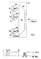
- Fig. 1
- die wesentlichen Merkmale des neuen Kabelfernseh-Verteilnetzes,
- Fig. 2
- die Struktur des in Fig. 1
vorhandenen Zeitmultiplexers 124 und - Fig. 3
- einen Frequenzplan eines zukünftigen Kabelfernseh-Systems mit einem Bereich, in den erfindungsgemäß Signale des Abruf-Video-Dienstes einfügbar sind.
- Fig. 1
- the main features of the new cable television distribution network,
- Fig. 2
- the structure of the time multiplexer 124 and
- Fig. 3
- a frequency plan of a future cable television system with an area in which signals of the video-on-demand service can be inserted according to the invention.
Die Fig. 1 zeigt in ihrem oberen Teil das im wesentlichen bekannte Kabelfernseh-Verteilnetz, wie es z.B. in der oben genannten Veröffentlichung Elektrisches Nachrichtenwesen, 4. Quartal 1992 in Bild 3 auf S. 60 gezeigt ist.1 shows in its upper part what is essentially known Cable television distribution network, e.g. in the above Publication electrical communications, 4th quarter 1992 in Picture 3 on p. 60 is shown.
In einer Kabelfernseh-Zentrale 100 befindet sich ein
Elektrisch-Optisch-Wandler 101, der das gesamte Signalgemisch zum
Übertragen der Kabelfernseh-Programme und Tonprogramme, als KTV
bezeichnet, in ein optisches Signal mit einer Wellenlänge λ1
von 1550 nm umsetzt. Dieses optische Signal gelangt über ein
Lichtwellenleiterverteilnetz, von dem ein Lichtwellenleiter 102,
ein Strahlteiler 103, ein von diesem zu einem Strahlteiler 105
führender Lichtwellenleiter 104 und ein von dem Strahlteiler 104 zu
einem optischen Netzabschluß (ONTi) führender Lichtwellenleiter
106 gezeigt sind, zu einer Anzahl von optischen Netzabschlüssen,
die gleich 64 ist, wenn die Strahlteiler einen Teilungsfaktor von 8
haben. Der gezeigte optische Netzabschluß (ONTi) ist
repräsentativ für alle 64, der Lichtwellenleiter 104 und der
Strahlteiler 105 ist respräsentativ für jeweils acht ebensolche,
und faseroptische Verstärker, die an verschiedenen Stellen des
Lichtwellenleiter-Verteilnetzes vorhanden sind, sind in der
Zeichnung weggelassen.In a
Für jeden optischen Netzabschluß wird im folgenden zur
Vereinfachung die Abkürzung ONT (ONT = Optical Network Terminal)
verwendet, bisweilen versehen mit dem Index i, wenn ausgedrückt
werden soll, daß es sich um den ONT NR. i von 64 ONT's handelt. In
jedem ONT endet der Lichtwellenleiter am Eingang eines
Optisch-Elektrisch-Wandlers 107.For each optical network termination is in the following
Simplify the abbreviation ONT (ONT = Optical Network Terminal)
used, sometimes with the index i when expressed
should be that it is the ONT NR. i is about 64 ONT's. In
Each ONT ends the optical fiber at the entrance of one
Optical-
Von jedem ONT führt, wie es für den optischen Netzabschluß ONTi
gezeigt ist, ein elektrisches Anschlußnetz, praktisch ein
Koaxialkabel-Netz, das sich wie gezeigt ebenfalls mehrfach
verzweigt, zu Kabelfernseh-Anschlüssen bei Teilnehmern, von denen
ein Teilnehmer 111 symbolisch durch ein Haus dargestellt ist. Das
Anschlußnetz endet, bei jedem Teilnehmer an einem
Kabelfernseh-Hausübergabepunkt. Im gezeigten Beispiel verzweigt
sich das elektrische Anschlußnetz von einer Leitung 108 zunächst an
einem Kabelverzweiger 109 auf vier Leitungen 110, von denen jede
8-fach verzweigt ist und sich beim Teilnehmer 111 nochmals auf zwei
Leitungen verzweigt. Somit wird über das
Lichtwellenleiter-Verteilnetz und die elektrischen Anschlußnetze
das in der Zentrale bereitgestellte Kabelfernseh-Gemisch auf eine
Vielzahl von Teilnehmern verteilt, in dem hier betrachteten
Beispiel auf 4096 Teilnehmer. From each ONT, as shown for the optical network termination ONT i , an electrical connection network, practically a coaxial cable network, which, as shown, also branches out several times, leads to cable television connections for subscribers, of whom a subscriber 111 symbolically walks through a house is shown. The connection network ends at each subscriber at a cable television house transfer point. In the example shown, the electrical connection network branches from a
Gemäß der Erfindung ist das beschriebene Kabelfernseh-Verteilnetz
wie folgt erweitert, um den Teilnehmern die Möglichkeit zu bieten,
von einem Abruf-Video-Dienst Gebrauch zu machen. In der Zentrale
100 befinden sich von dem Anbieter des Abruf-Video-Dienstes
betriebene Speicher für Videofilme, z.B. eine Anzahl von
Video-Kassettenrekordern (VCR), von den beispielsweise zwei gezeigt
und mit 120 und 121 bezeichnet sind. Äußert ein Teilnehmer über
eine Telefonverbindung oder einen im Kabelfernseh-Verteilnetz
einzurichtenden Rückkanal den Wunsch, einen bestimmten Videofilm zu
sehen, so wird dieser z.B. in einen der Video-Kassettenrekorder
eingelegt und abgespielt. Die Ausgänge der Video-Kassettenrekorder
sind mit Eingängen einer Vermittlungseinrichtung 122 verbunden, die
entsprechend dem Wunsch des Teilnehmers so gesteuert wird, daß der
Videofilm in einem Kanal in Richtung zu dem Teilnehmer übertragen
wird, zu dem dieser Zugriff hat. Zu diesem Zweck sind die Ausgänge
der Vermittlungseinrichtung 122 in Gruppen eingeteilt, wobei jede
Gruppe genau einem der ONT's zugeordnet ist. Die zu einer Gruppe
von Ausgängen gehörenden Ausgänge repräsentieren Kanäle, zu denen
die Teilnehmer, die an den ONT, dem die Gruppe zugeordnet ist,
Zugriff haben. Da in dem für das Verständnis der Erfindung
betrachteten Beispiel die Zahl der ONT's gleich 64 ist, gibt es
also, wie in der Zeichnung angedeutet, 64 Gruppen von Ausgängen der
Vermittlungseinrichtung 122. Mit anderen Worten: Es gibt 64 Gruppen
von Kanälen, in denen Videosignale zu Teilnehmern des
Kabelfernseh-Verteilnetzes übertragbar sind.According to the invention, the cable television distribution network described
expanded as follows to give participants the opportunity
to make use of an on-demand video service. In the
Erfindungsgemäß erfolgt die Übertragung der Videosignale in den Kanälen digital. Die Bitfolgefrequenz zur Übertragung eines Videosignals in einem Kanal orientiert sich einerseits an den zur Verfügung stehenden Video-Codierungsverfahren und andererseits an dem Qualitätsanspruch, der an das Videosignal gestellt ist. Wie aus der eingangs genannten Veröffentlichung JOURNAL OF LIGHTWAVE TECHNOLOGY bekannt, gibt es Codierverfahren, die es erlauben, ein Videosignal mit guter Kabelfernseh-Qualität mit einer Bitfolgefrequenz von 6 Mbit/s zu übertragen.According to the invention, the video signals are transmitted in the Channels digital. The bit rate for the transmission of a Video signals in a channel are based on the one hand Available video coding method and on the other hand the quality demands placed on the video signal. How from the publication JOURNAL OF LIGHTWAVE mentioned at the beginning TECHNOLOGY known, there are coding methods that allow one Video signal with good cable television quality with one To transmit bit rate of 6 Mbit / s.
Für das zur Erläuterung der Erfindung betrachtete Beispiel wird
also davon ausgegangen, daß die Bitfolgefrequenz in einem Kanal
6 Mbit/s beträgt. Weiter wird davon ausgegangen, daß entsprechend
der geschätzten Akzeptanz des Abruf-Video-Dienstes es ausreichen
wird, wenn für eine Gruppe von an einen ONT angeschlossenen
Teilnehmern sechs Kanäle zur Verfügung stehen. Hiervon ausgehend
sind also im betrachteten Beispiel 64 Kanalgruppen vorhanden (für
jeden optischen Netzabschluß eine) und jede Kanalgruppe hat sechs
Kanäle mit einer Bitfolgefrequenz von 6 Mbit/s in jedem Kanal.For the example considered to explain the invention
So assumed that the bit rate in a
Im betrachteten Beispiel ist angenommen, daß die Videosignale in
ihrer Quelle in analoger Form vorliegen und die
Vermittlungseinrichtung ebenfalls in analoger Form durchlaufen.
Daher befindet sich in jeder Ausgangsleitung der
Vermittlungseinrichtung 122 ein Analog-Digital-Wandler 123, in
anderen Worten: ein Videocodierer. Statt dessen ist es auch
möglich, daß die Videosignale in dem Speicher, aus dem sie abrufbar
sind, z.B. in einem magnetischen oder optischen
Massenspeicher-Laufwerk, in komprimierter digitaler Form vorliegen,
so daß die Analog-Digital-Wandler 123 nicht erforderlich sind.In the example considered, it is assumed that the video signals in
their source are in analog form and the
Go through switching center also in analog form.
For this reason, the
Damit die zu übertragenden teilnehmerindividuellenen Videosignale nur von denjenigen Teilnehmern empfangbar sind, die sie bestellt haben und für sie bezahlen, werden sie mit einem teilnehmerindividuellen Schlüssel verschlüsselt. Die Verschlüsselungseinrichtung, die für jeden Kanal in der Zentrale erforderlich ist, ist in der Zeichnung weggelassen. So that the individual video signals to be transmitted can only be received by the participants who ordered it have and pay for them, they will be with you subscriber-specific key encrypted. The Encryption facility for each channel in the headquarters is required is omitted from the drawing.
Ein Multiplexer 124 faßt die Videosignale aus den 64 Gruppen mit
jeweils 6 Kanälen zu einem Zeitmultiplex-Signal zusammen, das an
seinem mit ZM bezeichneten Ausgang erscheint (bisweilen werden
Signale ebenso wie die sie führenden Leitungen bezeichnet), ein
Elektrisch-Optisch-Wandler 125 setzt es in ein optisches Signal mit
einer Wellenlänge λ2 von z.B. 1530 nm um, und ein
Wellenlängen-Multiplexer 126, der ein faseroptischer Koppler ist,
koppelt das optische Signal mit der Wellenlänge λ2 in denselben
Lichtwellenleiter 102 ein, der auch das Gemisch der
Kabelfernseh-Signale als optisches Signal mit der Wellenlänge
λ1 führt. Somit ist dafür gesorgt, daß die Gesamtheit von
digitalen teilnehmerindividuellen Videosignalen als
Zeitmultiplex-Signal im Wellenlängenmultiplex zusammen mit den
Kabelfernseh-Signalen zu den ONT's verteilt wird. Die in dem
Lichtwellenleiter-Verteilnetz vorhandenen faseroptischen Verstärker
sind für beide Wellenlängen geeignet.A
Im folgenden wird anhand von Fig. 2 die Struktur und Funktion des
Multiplexers 124 aus Fig. 1 erläutert. Der Multiplexer 124 hat, wie
bereits in Fig. 1 angedeutet, 64 Gruppen von Eingängen mit jeweils
6 Eingängen pro Gruppe. Er empfängt also Signale aus 64
Kanalgruppen, die in Fig. 2 mit KG1bis KG64 bezeichnet sind.
Für jede dieser Kanalgruppen enthält der Multiplexer 124 einen
Kanalmultiplexer, der die Videosignale aus den angeschlossenen
sechs Kanälen zu einem Gruppen-Multiplexsignal zusammenfaßt und
dabei in das entstehende Gruppen-Multiplexsignal Zusatzbits
einfügt, die zur Kennung der Kanalgruppe und zur Synchronisation
des das jeweilige Gruppen-Multiplexsignal wieder auflösenden
Demultiplexers dienen. Die Kanalmultiplexer sind mit KM1 bis
KM64 bezeichnet, die die Gruppen-Multiplexsignale führenden
Ausgänge mit G1 bis G64 und die Eingänge der Kanalmultiplexer,
in die aus nicht gezeigten Quellen die Zusatzbits eingegeben
werden, sind mit S1 bis S64 bezeichnet. The structure and function of the
Das von einem Kanalmultiplexer gebildete Gruppen-Multiplexsignal hat eine Bitfolgefrequenz von 38,875 MHz, wenn jeder der sechs Kanäle eine Bitfolgefrequenz von 6 Mbit/s und die Anzahl der eingefügten Zusatzbits so ist, daß sich aus der Netto-Bitfolgefrequenz von 36 Mbit/s und den Zusatzbits die Bitfolgefrequenz von 38,875 Mbit/s ergibt. Die Kanalmultiplexer können nach irgend einem beliebigen Zeitmultiplex-Verfahren arbeiten.The group multiplex signal formed by a channel multiplexer has a bit rate of 38.875 MHz when each of the six Channels a bit rate of 6 Mbit / s and the number of inserted additional bits is such that the Net bit rate of 36 Mbit / s and the additional bits Bit rate of 38.875 Mbit / s results. The channel multiplexers can be by any time division method work.
Statt der Bitfolgefrequenz von 6 Mbit/s pro Kanal können auch andere Bitfolgefrequenzen, z.B. 2 Mbit/s vorliegen, auch Kanäle mit unterschiedlichen Bitfolgefrequenzen innerhalb einer Kanalgruppe. Vorteilhaft können auch z.B. drei 2-Mbit/s-Kanäle zu einem Standard 6-Mbit/s-Kanal im Zeitmultiplex zusammengefaßt sein bis zur Decodierung beim Teilnehmer zusammengefaßt bleiben. Wesentlich für die Erfindung ist nur, daß ein Kanalmultiplexer diejenigen Videosignale zu einem Gruppen-Multiplexsignal im Zeitmultiplex zusammenfaßt, die für Teilnehmer bestimmt sind, die an denselben ONT angeschlossen sind. Jeder Kanalmultiplexer ist also genau einem der ONT's zugeordnet.Instead of the bit rate of 6 Mbit / s per channel, you can also other bit repetition frequencies, e.g. 2 Mbit / s are available, including channels with different bit rate frequencies within a channel group. Advantageously, e.g. three 2 Mbit / s channels to one standard 6 Mbit / s channel can be combined in time division multiplexing up to Decoding remain summarized at the participant. Essential for the invention is only that a channel multiplexer ones Video signals to a group multiplex signal in time division multiplex summarizes, which are intended for participants who participate in the same ONT are connected. So each channel multiplexer is exactly one assigned to the ONT's.
In der Zeitmultiplexeinrichtung 124 befindet sich auch ein
Gruppen-Multiplexer, dessen Eingangssignale die
Gruppen-Multiplexsignale G1 bis G64 sind, und der diese zu
einem Zeitmultiplexsignal zusammenfaßt, das an seinem mit ZM
bezeichneten Ausgang erscheint. Die Bitfolgefrequenz des
entstehenden Zeitmultiplexsignals ist 2,488 Gbit/s (64x38,875
Mbit/s).In the
Das Zusammenfassen der 64 Eingangssignale zu einem Zeitmultiplexsignal im Gruppen-Multiplexer GM kann prinzipiell nach irgendeinem beliebigen Zeitmultiplexverfahren geschehen. Vorteilhaft für die Ausführung der Erfindung ist eine bitweise Verschachtelung der 64 digitalen Eingangssignale G1 bhis G64. In principle, the 64 input signals can be combined to form a time-division multiplex signal in the group multiplexer GM using any desired time-division multiplex method. Bit-by-bit interleaving of the 64 digital input signals G 1 to G 64 is advantageous for the implementation of the invention.
Dies bedeutet, daß jedes 64. Bit des vom Gruppenmultiplexer GM erzeugten Zeitmultiplexsignals ein Bit desselben Gruppen-Multiplexsignals ist z.B. ein Bit von G1.This means that every 64th bit of the time division multiplex signal generated by the group multiplexer GM is a bit of the same group multiplex signal, for example a bit of G 1 .
Um die Erfindung weiter zu beschreiben, wird nun wieder auf Fig. 1
Bezug genommen. Wie oben erwähnt, wird das die Gesamtheit aller
Videosignale enthaltende Zeitmultiplexsignal ZM an alle 64 ONT's
verteilt. Jeder der ONT's, von denen einer gezeigt und mit ONTi
bezeichnet ist, empfängt und verarbeitet das Zeitmultiplexsignal
wie folgt:
Er enthält einen Wellenlängen-Demultiplexer 130, der im einfachsten
Falle, wie zeichnerisch angedeutet, ein wellenlängenselektiver
Faserschmelzkoppler ist. Dieser koppelt aus dem
Wellenlängen-Multiplexsignal das optische Signal mit der
Wellenlänge λ2 aus und leitet es auf den Eingang eines
Optisch-Elektrisch-Wandlers 131. An dessen Ausgang erscheint das
sendeseitig erzeugte elektrische Zeitmultiplexsignal ZM. Es wird in
einem Regenerator 132 regeneriert und gelangt dann auf einen
Selektor 133. Dieser hat die Aufgabe, aus dem Zeitmultiplexsignal
das Gruppen-Multiplexsignal zu entnehmen, das für die Gruppe der an
den optischen Netzabschluß angeschlossenen Teilnehmer bestimmt ist,
das also diejenigen teilnehmerindividuellen Videosignale enthält,
die für diese Teilnehmer bestimmt sind.To further describe the invention, reference is now made to FIG. 1 again. As mentioned above, the time-division multiplex signal ZM containing all of the video signals is distributed to all 64 ONTs. Each of the ONT's, one of which is shown and labeled ONT i , receives and processes the time division multiplex signal as follows:
It contains a wavelength demultiplexer 130, which in the simplest case, as indicated in the drawing, is a wavelength-selective fiber fusion coupler. This decouples the optical signal with the wavelength λ 2 from the wavelength multiplex signal and forwards it to the input of an optical-
Der Selektor 133 ist besonders einfach, wenn das
Zeitmultiplexsignal, wie oben erwähnt, durch bitweise
Verschachtelung der Gruppen-Multiplexsignale gebildet ist. Er
tastet dann einfach das Zeitmultiplexsignal mit einem Takt ab,
dessen Frequenz gleich einem 64stel des Bittakts des
Zeitmultiplexsignals ZM (2,488 GHz) ist. Jedes 64ste Bit des
Zeitmultiplexsignals gehört nämlich zu einem
Gruppen-Multiplexsignal. Die Abtastung ergibt also einen Bitstrom,
der ein Gruppen-Multiplexsignal ist. The
Nun muß der Selektor 133 noch überprüfen, ob das durch die
Abtastung entnommene Gruppen-Multiplexsignal das für den ONT
bestimmte oder das für einen anderen ONT bestimmte ist. Zu diesem
Zweck überprüft er die dem Gruppen-Multiplexsignal beigefügte
Kennung. Stellt er fest, daß gemäß der Kennung das entnommene
Gruppen-Multiplexsignal das für den ONT bestimmte ist, so behält er
die Phase seines Abtasttaktes bei, findet er in dem
Gruppen-Multiplexsignal die eigene Kennung nicht, so stellt er
fest, daß dieses nicht für ihn bestimmt ist und verschiebt die
Phase des Abtasttaktes um eine Bitperiode des Zeitmultiplexsignals,
prüft wieder die Kennung solange, bis er bei irgend einer
Abtastphase festgestellt hat, daß das abgetastete
Gruppen-Multiplexsignal das für den betrachteten ONT bestimmte ist.
Stattdessen ist es auch möglich, daß der Selektor aus der Differenz
zwischen der gesuchten Kennung und der gefundenen Kennung die
notwendige Phasenverschiebung errechnet und in einem einzigen
Schritt durchführt.Now the
Der Vorteil der sendeseitigen bitweisen Verschachtelung und der im optischen Netzabschluß stattfindenden einfachen Abtastung jedes 64sten Bits liegt darin, daß der Selektor mit einer Taktfrequenz arbeiten kann, die der niedrigen Bitfolgefrequenz von 38,875 Mbit/s angepaßt und nicht der um den Faktor 64 höheren Bitfolgefrequenz seines Eingangssignals.The advantage of bitwise nesting on the sending side and that in optical scanning taking place simple sampling each The 64th bit is that the selector has a clock frequency can work, the low bit rate of 38.875 Mbit / s adapted and not the bit repetition frequency which is higher by a factor of 64 of its input signal.
Am Ausgang des Selektors 133 erscheint ein Gruppen-Multiplexsignal
Gi das für den mit demselben Index seines Bezugszeichens versehenen
optischen Netzabschluß ONTi bestimmt ist. Es gelangt auf einen
Kanal-Demultiplexer, der das Gegenstück zu einem der in Fig. 2
gezeigten Kanalmultiplexer KMi ist und das
Gruppen-Multiplexsignal in seine einzelnen Videosignale, im
betrachteten Beispiel in die sechs Videosignale, zerlegt, die an
seinen parallelen Ausgängen erscheinen. A group multiplex signal Gi appears at the output of the
Diese sechs Videosignale, die für Teilnehmer bestimmt sind, die an den ONTi angeschlossen sind, werden nun wie folgt zu diesen übertragen. Der ONT enthält für jedes der sechs digitalen Videosignale einen Modulator, der das Videosignal einem Unterträger aufmoduliert. Die sechs Modulatoren sind mit M1 bis M6 bezeichnet. Die Modulation ist im einfachsten Fall eine Amplitudenumtastung des Unterträgers (engl. ASK=Amplitude Shift Keying).These six video signals, which are intended for participants connected to the ONT i , are now transmitted to them as follows. The ONT contains a modulator for each of the six digital video signals, which modulates the video signal onto a subcarrier. The six modulators are labeled M 1 to M 6 . In the simplest case, the modulation is an amplitude shift keying of the subcarrier (English ASK = Amplitude Shift Keying).
Die in den Modulatoren verwendeten Unterträger liegen in einem Frequenzbereich, der nicht für den Dienst des Kabelfernsehens belegt oder reserviert ist, jedoch innerhalb des übertragbaren Frequenzbandes des elektrischen Anschlußnetzes liegt. Fig. 3 zeigt den Frequenzplan der heutzutage und wahrscheinlich auch in Zukunft für den Dienst des Kabelfernsehens über elektrische Koaxialkabel gültig ist. Die sechs Unterträger, denen jeweils eines der sechs Videosignale aufmoduliert wird, liegen in Abständen von 6 MHz im Frequenzbereich von 411 bis 447 MHz. Der Bereich ist in Fig. 3 mit VOD ("Video On DEMAND" = Abruf-Video-Dienst) bezeichnet. Die anderen rechteckförmigen Flächen bezeichnen Frequenzbänder des Kabelfernsehens, die entweder durch Tonprogramme oder Kabelfernseh-Programme belegt sind oder belegt werden sollen.The subcarriers used in the modulators are in one Frequency range that is not for the service of cable television is occupied or reserved, but within the transferable Frequency band of the electrical connection network is. Fig. 3 shows the frequency plan of today and probably also in the future for the service of cable television via coaxial electrical cables is valid. The six subcarriers, each one of the six Video signals are modulated at intervals of 6 MHz Frequency range from 411 to 447 MHz. The area is in Fig. 3 with VOD ("Video On DEMAND" = on-demand video service) referred to. The other rectangular areas denote frequency bands of the Cable television, either through sound programs or Cable television programs are or should be occupied.
Fig. 1 zeigt einen Leistungsaddierer 135, der die sechs Unterträger
zu einem Frequenzmultiplexsignal zusammenfaßt, das ein weiterer
Leistungsaddierer 136 oder eine Frequenzweiche dem
Kabelfernseh-Signalgemisch wiederum im Frequenzmultiplex hinzufügt,
so daß schließlich vom Ausgang des Leistungsaddierers 136 ein
Signalgemisch mit Frequenzen gemäß Fig. 3, das sowohl die analogen
Kabelfernseh-Signale als auch die digitalen Abruf-Videosignale
enthält, über das elektrische Anschlußnetz zu den an den
betrachteten ONTi angeschlossenen Teilnehmern verteilt wird. 1 shows a power adder 135, which combines the six subcarriers into a frequency division multiplex signal, which another
Das Signalgemisch empfangen nun alle diese Teilnehmer, aber nur der Teilnehmer, der ein darin enthaltenes Abruf-Video-Signal angefordert hat, bekommt den Schlüssel mitgeteilt, mit dem er das angeforderte Signal entschlüsseln kann, damit es mit Hilfe seines Video-Decodierers decodiert werden kann. Stattdessen ist es auch möglich, daß ein Teilnehmer, der sich für den Abruf-Video-Dienst interessiert, sich bei dem Anbieter des Dienstes ein einziges Mal einen festen, ihm individuell zugeordneten, Schlüssel besorgt, der beispielsweise auf einer Magnetkarte gespeichert ist und mit Hilfe der in seinen Video-Decodierer eingesteckten Magnetkarte diesen in die Lage versetzt, das nur für ihn bestimmte Videosignal zu decodieren. Es ist dann nicht notwendig, einem Teilnehmer jedesmal den Schlüssel mitzuteilen, wenn an ihn ein Videosignal gesendet wird.The signal mixture now receives all these participants, but only the Subscriber who has an on-demand video signal contained therein requested, receives the key with which he does this can decrypt the requested signal so that it can use its Video decoder can be decoded. Instead, it is too possible for a subscriber to sign up for the on-demand video service interested in the provider of the service once obtains a fixed, individually assigned key, the for example, is stored on a magnetic card and with the help the magnetic card inserted into its video decoder the situation, the video signal intended only for him decode. It is then not necessary to have a participant every time notify the key when a video signal is sent to it becomes.
In jedem Falle hat das erfindungsgemäße System den Vorteil, daß jeder Teilnehmer Zugriff zu einem von sechs für den Dienst eingerichteten Kanälen hat, daß also die Kanalselektion erst beim Teilnehmer und nicht bereits im optischen Netzabschluß erfolgt. Dadurch ist es möglich, daß ein Teilnehmer gleichzeitig Videosignale auf mehreren Kanälen empfangen kann.In any case, the system according to the invention has the advantage that each subscriber has access to one out of six for the service channels set up, so that the channel selection only at Participants and not already in the optical network termination. This makes it possible for one participant to do the same Can receive video signals on multiple channels.
Die Anzahl von Kanälen für den Abruf-Video-Dienst, die einer Gruppe von an einen optischen Netzabschluß angeschlossenen Teilnehmern zur Verfügung stehen kann noch erhöht werden, wenn weitere Unterträger, die in durch den Dienst des Kabelfernsehens nicht belegten Frequenzbereichen liegen, verwendet werden, oder wenn die Codierung mit einer niedrigeren Bitfolgefrequenz erfolgt, so daß die Frequenzabstände zwischen den Unterträgern geringer sein können. Alternativ hierzu kann man auch die Abstände zwischen den Unterträgern beibehalten und die mit einer niedrigeren Bitfolgefrequenz codierten Signale zu einem Zeitmultiplexsignal mit z.B. 6Mbit/s zusammenfassen, das dann einem Unterträger aufmoduliert wird. The number of channels for the on-demand video service that a group of participants connected to an optical network termination Available can be increased if additional subcarriers, those not used in the service of cable television Frequency ranges are used, or if the coding done with a lower bit rate, so that Frequency spacings between the subcarriers can be smaller. Alternatively, you can also set the distances between the Keep subcarriers and those with a lower one Bit rate coded signals with a time-division multiplex signal e.g. 6Mbit / s summarize that then a subcarrier is modulated.
Nachstehend wird noch beschrieben, welche Vorgänge in dem erfindungsgemäßen System ablaufen, wenn ein Teilnehmer ein bestimmtes Videosignal, z.B. einen Videofilm, bestellt. Für solche Bestellungen kann entweder das Telefonnetz verwendet werden, oder ein Rückkanal, der zwischen den Teilnehmern und der Zentrale über das Kabelfernseh-Verteilnetz eingerichtet ist. Hat ein Teilnehmer, der zu einer Gruppe von Teilnehmern gehört, die an einem optischen Netzabschluß ONTi angeschlossen sind, einen Programmwunsch der Zentrale mitgeteilt, so sucht die Zentrale einen freien Kanal in der Kanalgruppe KGi, die dem optischen Netzabschluß ONTi, an den der Teilnehmer angeschlossen ist, zugeordnet ist. Ist beispielsweise der Kanal 1 der Kanalgruppe KGi frei, so teilt die Zentrale dem Teilnehmer mit, daß sein Wunschprogramm auf dem Kanal 1 empfangen werden kann gegebenenfalls auch die Uhrzeit, zu dem das Aussenden voraussichtlich beginnt. Diese Mitteilung erfolgt z.B. über das Telefonnetz oder über einen über das Kabelfernseh-Verteilnetz einzurichtenden Signalisierungskanal. Den Schlüssel, den die Zentrale zur Verschlüsselung des zu sendenden Videosignals verwendet, hat der Teilnehmer entweder auf einer Magnetkarte gespeichert oder bekommt ihn ebenfalls von der Zentrale mitgeteilt. Die Zentrale veranlaßt dann das Abspielen des gewünschten Videosignals, falls es in analoger Form vorliegt, die Analog-Digital-Wandlung und Kompression und in jedem Fall die Verschlüsselung mit dem teilnehmerindividuellen Schlüssel. Das zu sendende Videosignal gelangt über die Vermittlungseinrichtung der Zentrale dann auf den freien Kanal 1 der Kanalgruppe KGi. Damit ist sichergestellt, daß das Videosignal den Teilnehmer erreicht, der es bestellt hat.The following describes what happens in the system according to the invention when a participant orders a certain video signal, for example a video film. Either the telephone network can be used for such orders, or a return channel, which is set up between the subscribers and the control center via the cable television distribution network. If a subscriber who belongs to a group of subscribers who are connected to an optical network termination ONT i has communicated a program request to the central, the central searches for a free channel in the channel group KG i that corresponds to the optical network termination ONT i the subscriber is connected, is assigned. If, for example, channel 1 of channel group KG i is free, the control center informs the subscriber that his or her desired program can be received on channel 1, and possibly also the time at which transmission is likely to begin. This notification takes place, for example, via the telephone network or via a signaling channel to be set up via the cable television distribution network. The subscriber has either stored the key that the center uses to encrypt the video signal to be sent on a magnetic card or is also given it by the center. The control center then initiates the playback of the desired video signal, if it is in analog form, the analog-to-digital conversion and compression and in any case the encryption with the subscriber-specific key. The video signal to be sent then passes via the switching center to the free channel 1 of the channel group KG i . This ensures that the video signal reaches the subscriber who ordered it.
Es sei noch erwähnt, daß die Erfindung nicht auf die Übertragung von Videosignalen beschränkt ist. Selbstverständlich können auch andere Arten von Signalen, z.B. Audiosignale, auf Abruf zu Teilnehmern übertragen werden, wenn z.B. ein Teilnehmer eine bestimmte Tonaufnahme (z.B. Musik, Vorlesung, Vortrag) hören will. It should be noted that the invention is not applicable to the transfer of video signals is limited. Of course you can too other types of signals, e.g. Audio signals, on demand too Are transmitted to participants if e.g. one participant one wants to hear certain sound recordings (e.g. music, lectures, lectures).
Auch diese Übertragung geschieht dann wie für Videosignale beschrieben in digitalisierter Form, der Teilnehmer benötigt einen Audio-Decodierer, in den wie oben für Video-Decodierer beschrieben, der Schlüssel für die Entschlüsselung eingebbar ist. Verschiedene Audiosignale können im Zeitmultiplex zusammengefaßt einen einzigen Videokanal (z.B. mit 6Mbit/s) belegen und sich einen einzigen Modulator teilen.This transmission then also takes place as for video signals described in digitized form, the participant needs one Audio decoders, in those as described above for video decoders, the key for decryption can be entered. Various Audio signals can be combined into a single time-division multiplex Occupy video channel (e.g. with 6Mbit / s) and one Share modulator.
Abschließend sei noch erwähnt, daß die Einrichtungen, die erforderlich sind, um für die Zentrale das die Gesamtheit aller digitalen Videosignale enthaltende Zeitmultiplexsignal ZM zu bilden, nicht notwendigerweise örtlich bei der Zentrale angeordnet sein müssen. Sie können auch örtlich von der Zentrale abgesetzt sein, sogar viele Kilometer, so daß die von der Zentrale aus zu übertragenden Videosignale von den genannten Einrichtungen über eine Zubringer-Übertragungsstrecke zu der Zentrale übertragen werden.Finally, it should be mentioned that the facilities that are necessary to ensure that the entirety of all time-division multiplex signal ZM containing digital video signals form, not necessarily located locally at the headquarters have to be. You can also be dropped off locally from headquarters be, even many kilometers, so that from the headquarters too transmitting video signals from the above facilities a feeder transmission link to the control center be transmitted.
Claims (8)
- A cable television distribution network comprisingcharacterized in that the center (100) includes means (123 to 126) for making available the subscriber-assigned video signals as digital signals, for combining the entirety of digital subscriber-assigned video signals intended for subscribers connected to the optical network terminations (ONTi) into a time-division-multiplexed signal (ZM), and for optically distributing the signal (ZM) with the composite cable television signal to the optical network terminations (ONTi) using wavelength-division multiplexing and different wavelengths for the composite cable television signal and the time-division-multiplexed signal, and that each optical network termination (ONTi) includes means (130 to 136, M1 to M6) for receiving the time-division-multiplexed signal (ZM), for extracting therefrom the video signals (Gi) intended for subscribers connected to the optical network termination (ONTi), and for frequency-division-multiplexing said extracted video signals with the composite cable television signal which is distributed from the optical network termination (ONT1) to the subscribers (111) connected to said optical network termination (ONT1).a fiber-optic distribution network (101 to 107) extending from a center (100) to optical network terminations (ONTi),a respective electrical access network extending from each of the optical network terminations (ONTi) to a respective one of a plurality of groups of subscribers (111) for distributing a composite cable television signal to the subscribers, andmeans (120 to 125) in the center (100) for transmitting, in addition to cable television signals (KTV), subscriber-assigned video signals together with the composite cable television signal to the optical network terminations (ONTi) using wavelength-division multiplexing,
- A cable television distribution network as claimed in claim 1,
characterized in that the center (100) further includes:for each optical network termination (ONTi) a channel multiplexer (KM1 to KM64) which combines the video signals (KGi) intended for subscribers (111) connected to the respective optical network termination (ONTi) into a group multiplex signal (Gi) using time-division multiplexing; anda group multiplexer (GM) which combines the group multiplex signals (G1 to G64) into said time-division-multiplexed signal (ZM) (Fig. 2). - A cable television distribution network as claimed in claim 2,
characterized in that in the group multiplexer (GM), the group multiplex signals (G1 to G64) are bit-interleaved. - A cable television distribution network as claimed in claim 2,
characterized in that the means in each optical network termination (ONTi) include:a selector (133) which extracts the video signals intended for subscribers connected to the optical network termination (ONTi) as the group multiplex signal (Gi) from the time-division-multiplexed signal (ZM);a channel demultiplexer (134) which separates the group multiplex signal (Gi) into the individual digital video signals;modulators (M1 to M6) which each modulate one of the digital video signals onto a subcarrier; andpower combiners (135, 136) which combine the modulated subcarriers with the composite cable television signal using frequency-division multiplexing. - A cable television distribution network as claimed in claim 4,
characterized in that each of the modulators (M1 to M6) modulates the digital video signal onto the subcarrier by amplitude-shift keying, and that the subcarriers lie in a frequency range (VOD, Fig. 3) which is not occupied by the composite cable television signal. - A cable television distribution network as claimed in any one of the preceding claims, characterized in that it is designed to transmit audio signals instead of or in addition to the subscriber-assigned video signals in a corresponding manner.
- A cable television distribution network as claimed in claim 1 or 2, characterized in that the means making available the digital video signals and/or the means (Fig. 2) forming the time-division-multiplexed signal are located remote from the center.
- A cable television distribution network as claimed in claim 1 or 2, characterized in that the means making available the digital video signals and/or the means (Fig. 2) forming the time-division-multiplexed signal are located in the center.
Applications Claiming Priority (2)
| Application Number | Priority Date | Filing Date | Title |
|---|---|---|---|
| DE4323147A DE4323147A1 (en) | 1993-07-10 | 1993-07-10 | Cable television distribution network with on-demand video signal transmission |
| DE4323147 | 1993-07-10 |
Publications (3)
| Publication Number | Publication Date |
|---|---|
| EP0633698A2 EP0633698A2 (en) | 1995-01-11 |
| EP0633698A3 EP0633698A3 (en) | 1995-06-28 |
| EP0633698B1 true EP0633698B1 (en) | 1999-09-08 |
Family
ID=6492504
Family Applications (1)
| Application Number | Title | Priority Date | Filing Date |
|---|---|---|---|
| EP94110415A Expired - Lifetime EP0633698B1 (en) | 1993-07-10 | 1994-07-05 | Cable television distribution network with video signal transmission on demand |
Country Status (6)
| Country | Link |
|---|---|
| US (1) | US5517232A (en) |
| EP (1) | EP0633698B1 (en) |
| AU (1) | AU671913B2 (en) |
| DE (2) | DE4323147A1 (en) |
| ES (1) | ES2135513T3 (en) |
| NZ (1) | NZ260888A (en) |
Families Citing this family (37)
| Publication number | Priority date | Publication date | Assignee | Title |
|---|---|---|---|---|
| DE4337138C1 (en) * | 1993-10-30 | 1995-03-02 | Ant Nachrichtentech | Broadcast and television distribution network |
| US5752198A (en) * | 1994-11-14 | 1998-05-12 | Ericsson Inc. | Single site, split location trunked radio communications system |
| US5689801A (en) * | 1994-11-14 | 1997-11-18 | Ericsson Inc. | Power monitoring system for a single site, split location trunked radio communication system |
| DE19505578A1 (en) * | 1995-02-18 | 1996-08-22 | Sel Alcatel Ag | Optical transmission system for cable television signals and video and telecommunication signals |
| JP3581490B2 (en) * | 1996-06-25 | 2004-10-27 | ソニー株式会社 | Optical transmission device, digital signal transmission device, and digital signal transmission method |
| US5822102A (en) * | 1996-07-10 | 1998-10-13 | At&T Corp | Passive optical network employing upconverted 16-cap signals |
| DE19635989A1 (en) * | 1996-09-05 | 1998-03-12 | Sel Alcatel Ag | Transmitter for optical transmission of analog electrical signals and digital transmission system |
| US6055077A (en) * | 1997-02-25 | 2000-04-25 | Nynex Science & Technology, Inc. | Multimedia distribution system using fiber optic lines |
| DE19643872A1 (en) * | 1996-10-31 | 1998-05-07 | Alsthom Cge Alcatel | Optical network termination unit of a hybrid fiber optic coaxial cable access network |
| DE19701888A1 (en) | 1997-01-21 | 1998-07-23 | Alsthom Cge Alcatel | System for the optical transmission of information |
| US7224896B1 (en) | 1997-02-25 | 2007-05-29 | Telesector Resources Group, Inc. | Methods and apparatus for generating local oscillation signals |
| US6538781B1 (en) | 1997-02-25 | 2003-03-25 | John Beierle | Multimedia distribution system using fiber optic lines |
| US6151336A (en) * | 1998-02-11 | 2000-11-21 | Sorrento Networks, Inc. | Time division multiplexing expansion subsystem |
| US6400478B1 (en) | 1998-04-02 | 2002-06-04 | Sorrento Networks, Inc. | Wavelength-division-multiplexed optical transmission system with expanded bidirectional transmission capacity over a single fiber |
| US6298103B1 (en) | 1998-06-16 | 2001-10-02 | Sorrento Networks Corporation | Flexible clock and data recovery module for a DWDM optical communication system with multiple clock rates |
| US6437895B1 (en) * | 1999-04-05 | 2002-08-20 | Scientific-Atlanta, Inc. | Digital optical transmitter with compression |
| US6498663B1 (en) | 1999-09-24 | 2002-12-24 | Scientific-Atlanta, Inc. | Methods and systems for detecting optical link performance of an optical link in a hybrid fiber coaxial path |
| US7386236B1 (en) | 1999-09-27 | 2008-06-10 | Alloptic, Inc. | Multiple wavelength TDMA optical network |
| US8745682B1 (en) | 2000-03-13 | 2014-06-03 | Broadcom Corporation | Integrated cable modem and cable television management system |
| US7298975B2 (en) * | 2000-07-13 | 2007-11-20 | L-3 Communications Integrated Systems L.P. | Synchronous collapsed ring architecture for real-time signal switching and distribution |
| AU2001288408A1 (en) * | 2000-08-25 | 2002-03-04 | Centerpoint Broadband Technologies, Inc. | A fiber optic terminal system employing subcarrier multiplexing for high capacity optical data transport |
| DE10056390A1 (en) * | 2000-11-14 | 2002-05-23 | Daetwyler Ag | Broadband cable network for video services has network interface device limiting access of each subscriber to pay services |
| US7231655B2 (en) * | 2001-08-06 | 2007-06-12 | Time Warner Cable | Technique for reverse transport of data in a hybrid fiber coax cable system |
| WO2003088667A1 (en) * | 2002-04-12 | 2003-10-23 | Koninklijke Philips Electronics N.V. | Transmission method and system having mapped unicast frequency band |
| EP1499061A1 (en) * | 2003-07-17 | 2005-01-19 | Deutsche Thomson-Brandt Gmbh | Individual video encryption system and method |
| KR100539928B1 (en) * | 2003-08-29 | 2005-12-28 | 삼성전자주식회사 | Multi-wavelength light source and wavelength division multiplexing system using the same |
| KR20050070566A (en) * | 2003-12-30 | 2005-07-07 | 삼성전자주식회사 | Multi-wavelength light source and wavelength-division multiplexing system using the same |
| US7103073B2 (en) * | 2004-02-19 | 2006-09-05 | Advanced Fibre Communications, Inc. | Optical line termination, passive optical network, and method and apparatus for performance monitoring |
| US7603036B2 (en) * | 2006-01-06 | 2009-10-13 | Fujitsu Limited | System and method for managing network components in a hybrid passive optical network |
| JP4882614B2 (en) * | 2006-09-01 | 2012-02-22 | 富士通株式会社 | Bit rate mixed optical communication method, optical subscriber unit and optical station side unit |
| US20080310846A1 (en) * | 2007-06-13 | 2008-12-18 | West Jr Lamar E | Frequency modulated burst mode transmitter |
| US8589993B2 (en) * | 2008-08-29 | 2013-11-19 | At&T Intellectual Property I, L.P. | Distributing on-demand multimedia content |
| US8607272B2 (en) * | 2009-10-29 | 2013-12-10 | At&T Intellectual Property I, Lp | Near-real time internet protocol television |
| US9397898B2 (en) * | 2012-06-29 | 2016-07-19 | Infinera Corporation | Digital link viewer |
| US9351077B1 (en) | 2014-12-11 | 2016-05-24 | L-3 Communications Integrated Systems Lp | Systems and methods for independent and control-isolated audio processing (ICIAP) |
| US10397672B2 (en) * | 2016-06-20 | 2019-08-27 | Cable Television Laboratories, Inc. | Systems and methods for intelligent edge to edge optical system and wavelength provisioning |
| US10200123B2 (en) | 2016-06-20 | 2019-02-05 | Cable Television Laboratories, Inc. | System and methods for distribution of heterogeneous wavelength multiplexed signals over optical access network |
Family Cites Families (7)
| Publication number | Priority date | Publication date | Assignee | Title |
|---|---|---|---|---|
| JPH0652944B2 (en) * | 1984-02-23 | 1994-07-06 | 富士通株式会社 | Frequency synchronization method |
| JPH01305698A (en) * | 1988-06-02 | 1989-12-08 | Nec Corp | Wavelength and time division light distributing system |
| US5136411A (en) * | 1987-12-11 | 1992-08-04 | General Instrument Corporation | Dynamically responsive CATV system with shared fiber optic link |
| US5119188A (en) * | 1988-10-25 | 1992-06-02 | Telaction Corporation | Digital audio-video presentation display system |
| US5442700A (en) * | 1990-09-28 | 1995-08-15 | Ictv, Inc. | Scrambling method |
| JPH04357727A (en) * | 1991-06-03 | 1992-12-10 | Victor Co Of Japan Ltd | Signal transmission/reception system by catv line |
| US5418559A (en) * | 1992-10-23 | 1995-05-23 | At&T Corp. | Multi-channel television converter for conventional and interactive signals |
-
1993
- 1993-07-10 DE DE4323147A patent/DE4323147A1/en not_active Withdrawn
-
1994
- 1994-06-30 NZ NZ260888A patent/NZ260888A/en unknown
- 1994-07-01 AU AU66117/94A patent/AU671913B2/en not_active Ceased
- 1994-07-05 DE DE59408717T patent/DE59408717D1/en not_active Expired - Fee Related
- 1994-07-05 ES ES94110415T patent/ES2135513T3/en not_active Expired - Lifetime
- 1994-07-05 EP EP94110415A patent/EP0633698B1/en not_active Expired - Lifetime
- 1994-07-07 US US08/271,521 patent/US5517232A/en not_active Expired - Fee Related
Also Published As
| Publication number | Publication date |
|---|---|
| DE59408717D1 (en) | 1999-10-14 |
| AU6611794A (en) | 1995-01-19 |
| EP0633698A2 (en) | 1995-01-11 |
| AU671913B2 (en) | 1996-09-12 |
| NZ260888A (en) | 1996-07-26 |
| US5517232A (en) | 1996-05-14 |
| DE4323147A1 (en) | 1995-01-12 |
| ES2135513T3 (en) | 1999-11-01 |
| EP0633698A3 (en) | 1995-06-28 |
Similar Documents
| Publication | Publication Date | Title |
|---|---|---|
| EP0633698B1 (en) | Cable television distribution network with video signal transmission on demand | |
| EP0727889B1 (en) | Optical transmission system for cable television signals and video- and telecommunication signals | |
| EP0151454B1 (en) | Broadband integrated subscriber access system | |
| DE3614361C2 (en) | ||
| EP0193190B1 (en) | Optical-information transmission system in the subscriber region | |
| DE2807986A1 (en) | SYSTEM FOR INTERACTIVE CABLE TV | |
| EP0394728A2 (en) | Optical communication system for the subscriber connection area | |
| EP0020878A1 (en) | Service integrated information transmission and switching system for sound, picture and data | |
| DE4438942A1 (en) | Optical communication system for cable television signals and for subscriber-specific signals | |
| EP0380945A2 (en) | Optical broad-band communication transmission system, especially in the subscriber access area | |
| EP0386482B1 (en) | Optical data transmission system for subscriber connection | |
| EP0817410A2 (en) | Optical network terminal, optical network and switch for same | |
| EP0024618A1 (en) | Wide-band telecommunication system | |
| DE3632047C2 (en) | Optical communication system for narrowband and broadband message signals | |
| EP0031014B1 (en) | Telecommunication system | |
| DE3146468A1 (en) | Multiplex concept for a digital optical subscriber network | |
| EP0881791B1 (en) | System for optical transmission of information | |
| EP0012979B1 (en) | Method for the transmission of several signals via a lightwave guide link, in particular between an exchange and a subscriber's connection | |
| DE3422219A1 (en) | Optical data transmission system in the access network | |
| EP0854597A2 (en) | System of optical information transmission over plural optical transmission lines | |
| DE4226838B4 (en) | Optical broadband communication system for communication and distribution services | |
| DE3242028A1 (en) | Cable television system | |
| EP0701384B1 (en) | System, subscriber equipment, central and method for video on demand | |
| DE3129731A1 (en) | Digital broadband communications system | |
| EP0212261B1 (en) | Broad-band distribution and communication system |
Legal Events
| Date | Code | Title | Description |
|---|---|---|---|
| PUAI | Public reference made under article 153(3) epc to a published international application that has entered the european phase |
Free format text: ORIGINAL CODE: 0009012 |
|
| AK | Designated contracting states |
Kind code of ref document: A2 Designated state(s): CH DE ES FR GB IT LI SE |
|
| PUAL | Search report despatched |
Free format text: ORIGINAL CODE: 0009013 |
|
| AK | Designated contracting states |
Kind code of ref document: A3 Designated state(s): CH DE ES FR GB IT LI SE |
|
| 17P | Request for examination filed |
Effective date: 19950818 |
|
| 17Q | First examination report despatched |
Effective date: 19970721 |
|
| GRAG | Despatch of communication of intention to grant |
Free format text: ORIGINAL CODE: EPIDOS AGRA |
|
| GRAG | Despatch of communication of intention to grant |
Free format text: ORIGINAL CODE: EPIDOS AGRA |
|
| GRAH | Despatch of communication of intention to grant a patent |
Free format text: ORIGINAL CODE: EPIDOS IGRA |
|
| GRAH | Despatch of communication of intention to grant a patent |
Free format text: ORIGINAL CODE: EPIDOS IGRA |
|
| GRAA | (expected) grant |
Free format text: ORIGINAL CODE: 0009210 |
|
| RAP1 | Party data changed (applicant data changed or rights of an application transferred) |
Owner name: ALCATEL |
|
| AK | Designated contracting states |
Kind code of ref document: B1 Designated state(s): CH DE ES FR GB IT LI SE |
|
| PG25 | Lapsed in a contracting state [announced via postgrant information from national office to epo] |
Ref country code: SE Free format text: THE PATENT HAS BEEN ANNULLED BY A DECISION OF A NATIONAL AUTHORITY Effective date: 19990908 |
|
| REG | Reference to a national code |
Ref country code: CH Ref legal event code: EP |
|
| ITF | It: translation for a ep patent filed |
Owner name: JACOBACCI & PERANI S.P.A. |
|
| REF | Corresponds to: |
Ref document number: 59408717 Country of ref document: DE Date of ref document: 19991014 |
|
| GBT | Gb: translation of ep patent filed (gb section 77(6)(a)/1977) |
Effective date: 19990927 |
|
| REG | Reference to a national code |
Ref country code: ES Ref legal event code: FG2A Ref document number: 2135513 Country of ref document: ES Kind code of ref document: T3 |
|
| ET | Fr: translation filed | ||
| PLBE | No opposition filed within time limit |
Free format text: ORIGINAL CODE: 0009261 |
|
| STAA | Information on the status of an ep patent application or granted ep patent |
Free format text: STATUS: NO OPPOSITION FILED WITHIN TIME LIMIT |
|
| PG25 | Lapsed in a contracting state [announced via postgrant information from national office to epo] |
Ref country code: LI Free format text: LAPSE BECAUSE OF NON-PAYMENT OF DUE FEES Effective date: 20000731 Ref country code: CH Free format text: LAPSE BECAUSE OF NON-PAYMENT OF DUE FEES Effective date: 20000731 |
|
| 26N | No opposition filed | ||
| REG | Reference to a national code |
Ref country code: CH Ref legal event code: PL |
|
| REG | Reference to a national code |
Ref country code: GB Ref legal event code: IF02 |
|
| PGFP | Annual fee paid to national office [announced via postgrant information from national office to epo] |
Ref country code: FR Payment date: 20060714 Year of fee payment: 13 Ref country code: DE Payment date: 20060714 Year of fee payment: 13 |
|
| PGFP | Annual fee paid to national office [announced via postgrant information from national office to epo] |
Ref country code: GB Payment date: 20060720 Year of fee payment: 13 |
|
| PGFP | Annual fee paid to national office [announced via postgrant information from national office to epo] |
Ref country code: ES Payment date: 20060728 Year of fee payment: 13 |
|
| PGFP | Annual fee paid to national office [announced via postgrant information from national office to epo] |
Ref country code: IT Payment date: 20060731 Year of fee payment: 13 |
|
| GBPC | Gb: european patent ceased through non-payment of renewal fee |
Effective date: 20070705 |
|
| PG25 | Lapsed in a contracting state [announced via postgrant information from national office to epo] |
Ref country code: DE Free format text: LAPSE BECAUSE OF NON-PAYMENT OF DUE FEES Effective date: 20080201 |
|
| PG25 | Lapsed in a contracting state [announced via postgrant information from national office to epo] |
Ref country code: GB Free format text: LAPSE BECAUSE OF NON-PAYMENT OF DUE FEES Effective date: 20070705 |
|
| REG | Reference to a national code |
Ref country code: FR Ref legal event code: ST Effective date: 20080331 |
|
| PG25 | Lapsed in a contracting state [announced via postgrant information from national office to epo] |
Ref country code: FR Free format text: LAPSE BECAUSE OF NON-PAYMENT OF DUE FEES Effective date: 20070731 |
|
| REG | Reference to a national code |
Ref country code: ES Ref legal event code: FD2A Effective date: 20070706 |
|
| PG25 | Lapsed in a contracting state [announced via postgrant information from national office to epo] |
Ref country code: ES Free format text: LAPSE BECAUSE OF NON-PAYMENT OF DUE FEES Effective date: 20070706 |
|
| PG25 | Lapsed in a contracting state [announced via postgrant information from national office to epo] |
Ref country code: IT Free format text: LAPSE BECAUSE OF NON-PAYMENT OF DUE FEES Effective date: 20070705 |