EP0633103B1 - Chuck mechanism - Google Patents
Chuck mechanism Download PDFInfo
- Publication number
- EP0633103B1 EP0633103B1 EP93113285A EP93113285A EP0633103B1 EP 0633103 B1 EP0633103 B1 EP 0633103B1 EP 93113285 A EP93113285 A EP 93113285A EP 93113285 A EP93113285 A EP 93113285A EP 0633103 B1 EP0633103 B1 EP 0633103B1
- Authority
- EP
- European Patent Office
- Prior art keywords
- slide shaft
- chuck
- shaft
- axial direction
- collet chuck
- Prior art date
- Legal status (The legal status is an assumption and is not a legal conclusion. Google has not performed a legal analysis and makes no representation as to the accuracy of the status listed.)
- Expired - Lifetime
Links
- 241001465754 Metazoa Species 0.000 description 4
- 210000000988 bone and bone Anatomy 0.000 description 4
- 238000010276 construction Methods 0.000 description 2
- 230000002093 peripheral effect Effects 0.000 description 2
- 230000036346 tooth eruption Effects 0.000 description 2
- 238000002266 amputation Methods 0.000 description 1
- 238000013016 damping Methods 0.000 description 1
- -1 e.g. Substances 0.000 description 1
- 238000005516 engineering process Methods 0.000 description 1
- 210000000610 foot bone Anatomy 0.000 description 1
- 210000002411 hand bone Anatomy 0.000 description 1
- 238000003780 insertion Methods 0.000 description 1
- 230000037431 insertion Effects 0.000 description 1
- 239000000463 material Substances 0.000 description 1
- 238000000034 method Methods 0.000 description 1
- 239000002023 wood Substances 0.000 description 1
Images


Classifications
-
- B—PERFORMING OPERATIONS; TRANSPORTING
- B23—MACHINE TOOLS; METAL-WORKING NOT OTHERWISE PROVIDED FOR
- B23B—TURNING; BORING
- B23B31/00—Chucks; Expansion mandrels; Adaptations thereof for remote control
- B23B31/02—Chucks
- B23B31/10—Chucks characterised by the retaining or gripping devices or their immediate operating means
- B23B31/12—Chucks with simultaneously-acting jaws, whether or not also individually adjustable
- B23B31/20—Longitudinally-split sleeves, e.g. collet chucks
- B23B31/201—Characterized by features relating primarily to remote control of the gripping means
- B23B31/202—Details of the jaws
-
- B—PERFORMING OPERATIONS; TRANSPORTING
- B23—MACHINE TOOLS; METAL-WORKING NOT OTHERWISE PROVIDED FOR
- B23D—PLANING; SLOTTING; SHEARING; BROACHING; SAWING; FILING; SCRAPING; LIKE OPERATIONS FOR WORKING METAL BY REMOVING MATERIAL, NOT OTHERWISE PROVIDED FOR
- B23D51/00—Sawing machines or sawing devices working with straight blades, characterised only by constructional features of particular parts; Carrying or attaching means for tools, covered by this subclass, which are connected to a carrier at both ends
- B23D51/08—Sawing machines or sawing devices working with straight blades, characterised only by constructional features of particular parts; Carrying or attaching means for tools, covered by this subclass, which are connected to a carrier at both ends of devices for mounting straight saw blades or other tools
- B23D51/10—Sawing machines or sawing devices working with straight blades, characterised only by constructional features of particular parts; Carrying or attaching means for tools, covered by this subclass, which are connected to a carrier at both ends of devices for mounting straight saw blades or other tools for hand-held or hand-operated devices
-
- B—PERFORMING OPERATIONS; TRANSPORTING
- B23—MACHINE TOOLS; METAL-WORKING NOT OTHERWISE PROVIDED FOR
- B23D—PLANING; SLOTTING; SHEARING; BROACHING; SAWING; FILING; SCRAPING; LIKE OPERATIONS FOR WORKING METAL BY REMOVING MATERIAL, NOT OTHERWISE PROVIDED FOR
- B23D51/00—Sawing machines or sawing devices working with straight blades, characterised only by constructional features of particular parts; Carrying or attaching means for tools, covered by this subclass, which are connected to a carrier at both ends
- B23D51/16—Sawing machines or sawing devices working with straight blades, characterised only by constructional features of particular parts; Carrying or attaching means for tools, covered by this subclass, which are connected to a carrier at both ends of drives or feed mechanisms for straight tools, e.g. saw blades, or bows
-
- B—PERFORMING OPERATIONS; TRANSPORTING
- B23—MACHINE TOOLS; METAL-WORKING NOT OTHERWISE PROVIDED FOR
- B23B—TURNING; BORING
- B23B2231/00—Details of chucks, toolholder shanks or tool shanks
- B23B2231/20—Collet chucks
- B23B2231/201—Operating surfaces of collets, i.e. the surface of the collet acted on by the operating means
- B23B2231/2021—Operating surfaces of collets, i.e. the surface of the collet acted on by the operating means comprising two different cones
-
- Y—GENERAL TAGGING OF NEW TECHNOLOGICAL DEVELOPMENTS; GENERAL TAGGING OF CROSS-SECTIONAL TECHNOLOGIES SPANNING OVER SEVERAL SECTIONS OF THE IPC; TECHNICAL SUBJECTS COVERED BY FORMER USPC CROSS-REFERENCE ART COLLECTIONS [XRACs] AND DIGESTS
- Y10—TECHNICAL SUBJECTS COVERED BY FORMER USPC
- Y10T—TECHNICAL SUBJECTS COVERED BY FORMER US CLASSIFICATION
- Y10T279/00—Chucks or sockets
- Y10T279/17—Socket type
- Y10T279/17411—Spring biased jaws
- Y10T279/17529—Fixed cam and moving jaws
- Y10T279/17538—Threaded-sleeve actuator
-
- Y—GENERAL TAGGING OF NEW TECHNOLOGICAL DEVELOPMENTS; GENERAL TAGGING OF CROSS-SECTIONAL TECHNOLOGIES SPANNING OVER SEVERAL SECTIONS OF THE IPC; TECHNICAL SUBJECTS COVERED BY FORMER USPC CROSS-REFERENCE ART COLLECTIONS [XRACs] AND DIGESTS
- Y10—TECHNICAL SUBJECTS COVERED BY FORMER USPC
- Y10T—TECHNICAL SUBJECTS COVERED BY FORMER US CLASSIFICATION
- Y10T279/00—Chucks or sockets
- Y10T279/17—Socket type
- Y10T279/17564—Loose jaws
- Y10T279/17598—Fixed cam and moving jaws
- Y10T279/17606—Threaded sleeve and body
Definitions
- the present invention relates to a chuck mechanism and more particularly to a chuck mechanism for removably chucking a jig on a reciprocally-movable member.
- tooth cutting is carried out by using a cutting tool to be driven by a micromotor rotating at high speed.
- a cutting tool to be driven by a micromotor rotating at high speed.
- specialists being engaged, for example, in medical treatment of hands or feet only.
- operations such as bone amputation or cutting, but no cutting device which is suitable for use in medical treatment of hands or feet, has been developed. Every specialist feels inconvenienced not having it.
- the present applicant previously proposed a cutting device which is suitable for amputating and/or cutting fine bones of hands and feet of human and animals.
- the proposed cutting device has a chuck mechanism for converting rotational movement of a shaft into linear reciprocal movement of a member reciprocally movable in an axial direction of the shaft and for removably chucking a jig to the reciprocally movable member to conduct various kinds of operation by use of the jig.
- the chuck clamping member has an increased diameter to be easily tightened or loosened when mounting or removing of a saw in or from the chuck.
- the chuck clamping member has a small diameter, it is hard to handle the chuck to clamp or release when mounting or removing of the sawing plate in or from the chuck.
- It is an object of the present invention to provide a chuck mechanism comprising of a chuck clamping member having a grasping portion of a large diameter which is easy to handle when clamping or releasing a collet chuck and the reciprocating portion which has a reduced mass to ensure a smooth movement.
- It is another object of the present invention to provide a chuck mechanism comprising of a slide shaft locking member having a head for clamping a collet chuck at one end and an internally threaded portion at the other end for attracting the head toward the collet chuck and a body case for turning the slide shaft locking member in its axial direction to clamp or release a chuck,the slide shaft locking member together with the chuck can reciprocate without moving the body case, thereby mass of the reciprocally moving portion is reduced and a small part of the moving portion may be exposed outside the body case.
- FIG. 1 is a view for explaining an example of a conventional chuck mechanism.
- FIG. 2 is a sectional view showing a cutting device used a chuck mechanism of the present invention.
- FIG. 3 is a sectional view showing another cutting device used a chuck mechanism of the present invention.
- FIGs. 4(a)-4(e) are an exploded views of components of the chuck mechanism shown in Figs. 2 and 3.
- FIGs. 5(a) and 5(b) are detailed views of a chuck clamping member and an intermediate member shown in Figs. 4(c) and 4(b).
- FIG. 6 shows a sectional view for explaining of connecting portion of a cutting device.
- Fig. 1 is a constructional view for explaining a cutting device proposed by the present applicant (Japanese publication of unexamined patent application No. 3-124894).
- numeral 1 denotes a rotation shaft connected to a rotation shaft to be driven by, for example, a micromotor known for use in dental treatment devices
- numeral 2 indicates a bevel gear mounted on the top of the rotation shaft 1
- numeral 3 designates a second rotation shaft being rotatable about an axis perpendicular to the axis of the rotation shaft 1 by means of a second bevel gear 4 that is mounted on the second rotation shaft 3 and engages with the bevel gear 2.
- the rotation shaft 3 is provided with two eccentric shafts 3a and 3b arranged at 180° apart from each other about the axis of the rotation shaft 3.
- Numeral 5 denotes a link engaged at its one end with the eccentric shaft 3a and at its opposite end with a pin 5a whereto a first-reciprocating member 6 is connected.
- a guide pin 7 is provided to assure smooth movement of the reciprocating member 6.
- a chuck 8 has an expanding slot in its axial direction.
- a chuck clamping member 9 threadedly engages with the first reciprocating member 6.
- a jig or saw 10 is inserted into the chuck clamping member 9 in loosened state and secured to the first reciprocating member 6 by tightening the chuck clamping member 9.
- a link 11 engages at its one end with the eccentric shaft 3b and at its opposite end with a pin 11a whereon the second reciprocating member 12 is mounted.
- revolution of the eccentric shaft 3b through the link 11 and the pin 11a is transmitted to the second reciprocating member 12 which reciprocally moves along the same axis but in the direction opposite to that of first reciprocating member 6 because the eccentric shafts 3a and 3b are located 180° apart about the axis of the rotation shaft 3.
- the second reciprocating member 12 acts as a damping member for the first reciprocating member 6. In other words, it serves as a balancer of the rotating shaft 3, which makes rotation of the shaft 3 stabilized to ensure smooth reciprocation of the saw 10.
- the chuck clamping member 9 has an increased diameter to be easily tightened or loosened when mounting or removing of the saw 10 in or from the chuck 8.
- the chuck clamping member 9 has a small diameter, it is hard to handle the chuck to clamp or release when mounting or removing of the saw 10 in or from the chuck 8.
- the use of the chuck clamping member 9 of increased diameter may cause unstable reciprocal movement of the member due to its increased mass. Furthermore, reciprocation of the chuck clamping member 9 of large diameter in the exposed state is dangerous in itself.
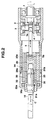
- Fig. 2 is a sectional construction view of an essential portion of a cutting device used a chuck mechanism of the present invention.
- numeral 1 denotes a rotation shaft connected to a rotation shaft to be driven by, for example, a micromotor known for use in dental treatment devices
- numeral 2 indicates a bevel gear mounted on the top of the rotation shaft 1
- numeral 3 designates a second rotation shaft being rotatable about an axis perpendicular to the axis of the rotation shaft 1 by means of a second bevel gear 4 that is mounted on the second rotation shaft and engages with the bevel gear 2.
- the rotation shaft 3 is provided with an eccentric shaft 3a.
- a connecting link 5 engages at its one end with the eccentric shaft 3a and at its opposite end with a pin 5a whereto a reciprocating member 29 is connected.
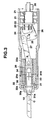
- Fig. 3 is another sectional construction view of an essential portion of a cutting device used a chuck mechanism of the present invention.
- numeral 1 indicates a rotation shaft with bearings 21 and connected with an eccentric revolution shaft 22 which has a bearing 23 loosely fitted in a recess 26 of a rocking member 24 being rockable about an axis 25 in the direction indicated by arrows A.
- the eccentric rotation shaft 22 rotates and causes the rocking member 24 to swing in the directions indicated by arrows A about the axis 25 since the bearing 23 fitted in the recess 26 of the rocking member may freely move in the direction perpendicular to the shown section of Fig. 3 but its vertical movement is limited by the recess of the rocking member 24.
- Rocking motion of the rocking member 24 in the direction A is transmitted through a connecting member 27 to a slide shaft 29 which reciprocates in the axial directions indicated by arrows B, and reciprocates the saw 10 along the axis indicated by arrows C.
- the shaft 22 revolves eccentrically in relation to the shaft 1 and its eccentric circular motion is converted by the rocking member 24 into reciprocal motion along the straight line. Consequently, the shaft 1 is subjected to eccentric load that may prevent smooth rotation of the shaft 1.
- a balance weight 28 for compensating the eccentric load is provided to assure smooth rotation of the shaft 1.
- the slide shaft 29 is threaded at its periphery for engaging with internal thread of a slide shaft locking member (chuck clamping member) 30.
- a collet chuck 31 is disposed between the slide shaft 29 and the slide shaft locking member 30.
- a saw 10 can be removably secured in the collet chuck 31.
- the slide shaft locking member rotates to loosen the threaded engagement with the slide shaft 29
- the slide shaft locking member 30 moves in the direction shown by arrows C, thereby the engagement between a clamping portion 31a of the collet chuck 31 and a chuck clamping head 30a of the slide shaft locking member 30 and the engagement between a clamping portion 31b of the collet chuck 31 and a chuck clamping portion 29a of the slide shaft 29 are released, allowing insertion or removal of the saw 10 in or from the collet chuck 31.
- An axis of the saw 10 is inserted in the opened collet chuck 31 and secured therein by the clamping portions 31a and 31b in the known manner when tightening the chuck clamping member 30 against the slide shaft 29.
- Figs. 2 and 3 utilize the collet chuck 31 with the clamping portions 31a and 31b formed, respectively, at both ends to reliably holding the saw 10 at two positions.
- the present invention is not limited to the shown embodiment and allows the use of a collet chuck having the clamping portion 31a only.
- the numeral 32 designates a body case (rotating member) for rotating the chuck clamping member (slide shaft locking member) 30 and has the tip peripheral portion 32a having an anti-slippingly finished surface, e.g., by knurling.
- the knurled portion 32a can be easily grasped when turning the body case 32.
- An intermediate member 33 can transmit the rotational movement of the body case 32 to the chuck clamping member 30.
- the intermediate member 33 has a slot 33a formed on its external surface in the axial direction, wherein an anti-rotation member 34 from the outside of the body case is fitted for transmitting the rotational movement of the body case 32 to the intermediate member 33 which in turn rotates the chuck clamping member 30.
- Movement of the intermediate member 33 in the axial direction can be prevented by securing said member 33 to the case body 32 by desired means. Any desired provision is made to prevent relative rotational movement of the intermediate member 33 and the slide shaft locking member (chuck clamping member) 30 and to allow relative axial movement of them. In the shown embodiment, this is achieved by using the chuck clamping member 30 having a hexagonal external profile and the intermediate member 33 having a hexagonal internal profile. However, their profiles shall not be limited to hexagonal form only.
- Figs. 4(a)-4(e) are exploded views of components of the chuck mechanism shown in Figs. 2 and 3.
- Fig. 4(a) indicates a body case 32 and a anti-rotation member 34
- Fig. 4(b) shows an intermediate member 33
- Fig. 4(c) indicates a slide shaft locking member (chuck clamping member)
- Fig. 4(d) shows a collet chuck 31
- Fig. 4(e) shows a slide shaft 29.
- Figs. 5(a) and 5(b) are detailed views of a slide shaft locking member (chuck clamping member) 30 (Fig. 5(a)) and an intermediate member 33 (Fig. 5(b)).
- the chuck clamping member 30 formed of hexagonal external profile 30b is fitted in the intermediate member 33 formed of hexagonal internal profile 33b to allow them to relatively move in the axial direction but not to allow their movement in the circumferential direction.
- this connecting method shall not be limited to use of hexagonal profile. It is possible to form the members to be of any profile (e.g., square, octagon, etc.) excepting a circular form permitting relative rotation of them. Key-and-keyway fitting is also applicable.
- the chuck mechanism according to the present invention can offer the following advantages:
- the chuck clamping member having a grasping portion of a large diameter is easy to handle when clamping or releasing a collet chuck and the reciprocating portion has a reduced mass to ensure a smooth movement. Furthermore chuck mechanism is safe to use since its moving portion has a least partial exposure and has a small diameter not to hit a part of human body or animal's body or other object during the medical treatment by use of a cutting tool clamped in the chuck mechanism.
- Fig. 6 is a sectional view for explaining a connecting portion of the device, by which the rotating portion and the reciprocating portion are steadily coupled with each other so that the latter may not slip out from the former.
- a rotation shaft side and reciprocating portion side are indicated by numerals I and II respectively.
- a rotation shaft 40 in a dental handpiece is driven by a micromotor (not shown) mounted in a power section and located in a center of a sleeve 41 having a peripheral groove 41a formed externally thereon.
- a mechanism for converting rotational movement of the rotation shaft 40 into the reciprocal movement in the axial direction of the shaft 40 comprises a connecting sleeve 42 that accommodates threin the rotation shaft 1 connected at its one end to the rotation shaft 40 and has a plurality of through holes 42a arranged in circumferential direction thereof.
- the sleeve 41 is slidably inserted in the axial direction in the connecting sleeve 42.
- Balls 43 are placed in each through-hole 42a of the connecting sleeve 42.
- the connecting sleeve 42 is accommodated in a sliding sleeve 44 which is slidable in its axial direction along the external surface of the connecting sleeve 42 and can be located at any of two positions 44a and 44b.
- This sliding sleeve 44 has an internally concaved portion 44c having an inner diameter D1 lager than an outer diameter D0 of the connecting sleeve 42.
- the sliding sleeve 44 is positioned at the first fixing position 44b (see the lower half of Fig. 6) with a concaved portion placed opposite to the balls 43 (see the lower half of Fig. 6), and the sleeve 41 is inserted into the connecting sleeve 42 in such a way that the balls 43 are fitted in the circular groove 41a of the sleeve 41(see the upper half of Fig. 6).
- the sliding sleeve 44 is located at the second fixing position 44a in such way that the ball 43 is placed in the circular groove 41a under the pressure of the inner wall surface of the sliding sleeve 44 (see the upper half of Fig. 6). This eliminates the possibility of disconnection of the connecting sleeve 42 from the sleeve 41.
- the rotation shaft portion I and reciprocating portion II are securely connected with each other by means of the balls 43 and the sliding sleeve 44 so as not to cause the reciprocating portion II to slip off from the rotor shaft portion I during operation of the device for converting the rotational movement of the rotation shaft 40 into reciprocal movement along the axis of the rotor shaft 40.
Landscapes
- Engineering & Computer Science (AREA)
- Mechanical Engineering (AREA)
- Dental Tools And Instruments Or Auxiliary Dental Instruments (AREA)
- Gripping On Spindles (AREA)
- Sawing (AREA)
Description
- The present invention relates to a chuck mechanism and more particularly to a chuck mechanism for removably chucking a jig on a reciprocally-movable member.
- In dental treatment, tooth cutting is carried out by using a cutting tool to be driven by a micromotor rotating at high speed. In recent years, with the progress of subdivision of medical areas and specialization of medical technology, there have appeared specialists being engaged, for example, in medical treatment of hands or feet only. In medical treatment of hands or feet, it is also necessary to carry out operations such as bone amputation or cutting, but no cutting device which is suitable for use in medical treatment of hands or feet, has been developed. Every specialist feels inconvenienced not having it.
- In view of the foregoing, the present applicant previously proposed a cutting device which is suitable for amputating and/or cutting fine bones of hands and feet of human and animals. The proposed cutting device has a chuck mechanism for converting rotational movement of a shaft into linear reciprocal movement of a member reciprocally movable in an axial direction of the shaft and for removably chucking a jig to the reciprocally movable member to conduct various kinds of operation by use of the jig.
- In the above-mentioned cutting device, the chuck clamping member has an increased diameter to be easily tightened or loosened when mounting or removing of a saw in or from the chuck. However, provided that the chuck clamping member has a small diameter, it is hard to handle the chuck to clamp or release when mounting or removing of the sawing plate in or from the chuck.
- It is an object of the present invention to provide a chuck mechanism comprising of a chuck clamping member having a grasping portion of a large diameter which is easy to handle when clamping or releasing a collet chuck and the reciprocating portion which has a reduced mass to ensure a smooth movement.
- It is another object of the present invention to provide a chuck mechanism which is safe to use by its moving portion of a least partial exposure.
- It is another object of the present invention to provide a chuck mechanism which has a small diameter not to hit a part of human body or animal's body or other object during the medical treatment.
- It is another object of the present invention to provide a chuck mechanism which is useful for cutting device used for amputating and/or cutting bones of human and animals or other kinds of material, e.g., wood and so on.
- It is another object of the present invention to provide a chuck mechanism comprising of a slide shaft locking member having a head for clamping a collet chuck at one end and an internally threaded portion at the other end for attracting the head toward the collet chuck and a body case for turning the slide shaft locking member in its axial direction to clamp or release a chuck,the slide shaft locking member together with the chuck can reciprocate without moving the body case, thereby mass of the reciprocally moving portion is reduced and a small part of the moving portion may be exposed outside the body case.
- FIG. 1 is a view for explaining an example of a conventional chuck mechanism.
- FIG. 2 is a sectional view showing a cutting device used a chuck mechanism of the present invention.
- FIG. 3 is a sectional view showing another cutting device used a chuck mechanism of the present invention.
- FIGs. 4(a)-4(e) are an exploded views of components of the chuck mechanism shown in Figs. 2 and 3.
- FIGs. 5(a) and 5(b) are detailed views of a chuck clamping member and an intermediate member shown in Figs. 4(c) and 4(b).
- FIG. 6 shows a sectional view for explaining of connecting portion of a cutting device.
- Fig. 1 is a constructional view for explaining a cutting device proposed by the present applicant (Japanese publication of unexamined patent application No. 3-124894). In Fig. 1,
numeral 1 denotes a rotation shaft connected to a rotation shaft to be driven by, for example, a micromotor known for use in dental treatment devices,numeral 2 indicates a bevel gear mounted on the top of therotation shaft 1, andnumeral 3 designates a second rotation shaft being rotatable about an axis perpendicular to the axis of therotation shaft 1 by means of asecond bevel gear 4 that is mounted on thesecond rotation shaft 3 and engages with thebevel gear 2. Therotation shaft 3 is provided with twoeccentric shafts rotation shaft 3. Numeral 5 denotes a link engaged at its one end with theeccentric shaft 3a and at its opposite end with apin 5a whereto a first-reciprocating member 6 is connected. Aguide pin 7 is provided to assure smooth movement of the reciprocatingmember 6. Achuck 8 has an expanding slot in its axial direction. Achuck clamping member 9 threadedly engages with the first reciprocatingmember 6. A jig orsaw 10 is inserted into thechuck clamping member 9 in loosened state and secured to the first reciprocatingmember 6 by tightening thechuck clamping member 9. Alink 11 engages at its one end with theeccentric shaft 3b and at its opposite end with apin 11a whereon the second reciprocatingmember 12 is mounted. - Accordingly, when the
rotation shaft 1 rotates, its rotational movement is transmitted to thesecond rotation shaft 3 through thebevel gears eccentric shafts eccentric shaft 3a in the direction perpendicular to the shown section of Fig. 1 is absorbed by thepin 5a and only its reciprocal movement in lateral direction, i.e., the axial direction of therotation shaft 1 is transmitted to the first reciprocatingmember 6, thereby the saw 10 reciprocates along the axis indicated by arrows C to cut a bone or the like by its cutting teeth. At the same time, revolution of theeccentric shaft 3b through thelink 11 and thepin 11a is transmitted to the secondreciprocating member 12 which reciprocally moves along the same axis but in the direction opposite to that of firstreciprocating member 6 because theeccentric shafts rotation shaft 3. Namely, while the firstreciprocating member 6 moves to the left (or the right), the secondreciprocating member 12 moves to the right (or the left). The second reciprocatingmember 12 acts as a damping member for the first reciprocatingmember 6. In other words, it serves as a balancer of the rotatingshaft 3, which makes rotation of theshaft 3 stabilized to ensure smooth reciprocation of thesaw 10. - In the above-mentioned cutting device, the
chuck clamping member 9 has an increased diameter to be easily tightened or loosened when mounting or removing of thesaw 10 in or from thechuck 8. However, provided that thechuck clamping member 9 has a small diameter, it is hard to handle the chuck to clamp or release when mounting or removing of thesaw 10 in or from thechuck 8. - On the other hand, the use of the
chuck clamping member 9 of increased diameter may cause unstable reciprocal movement of the member due to its increased mass. Furthermore, reciprocation of thechuck clamping member 9 of large diameter in the exposed state is dangerous in itself. - Fig. 2 is a sectional construction view of an essential portion of a cutting device used a chuck mechanism of the present invention. In Fig. 2,
numeral 1 denotes a rotation shaft connected to a rotation shaft to be driven by, for example, a micromotor known for use in dental treatment devices,numeral 2 indicates a bevel gear mounted on the top of therotation shaft 1, andnumeral 3 designates a second rotation shaft being rotatable about an axis perpendicular to the axis of therotation shaft 1 by means of asecond bevel gear 4 that is mounted on the second rotation shaft and engages with thebevel gear 2. Therotation shaft 3 is provided with aneccentric shaft 3a. A connectinglink 5 engages at its one end with theeccentric shaft 3a and at its opposite end with apin 5a whereto areciprocating member 29 is connected. - Accordingly, when the
rotation shaft 1 rotates, its rotational movement is transmitted to thesecond rotation shaft 3 through thebevel gears eccentric shaft 3a revolve. The eccentric motion of theeccentric shaft 3a in the direction perpendicular to the shown section of Fig. 2 is absorbed by thepin 5a and only its reciprocal movement in lateral direction, i.e., the axial direction A of therotation shaft 1 is transmitted to the reciprocatingmember 29, thereby the saw 10 reciprocates along the axis indicated by arrows C to cut a bone or the like by its cutting teeth. - Fig. 3 is another sectional construction view of an essential portion of a cutting device used a chuck mechanism of the present invention. In Fig. 3,
numeral 1 indicates a rotation shaft withbearings 21 and connected with aneccentric revolution shaft 22 which has abearing 23 loosely fitted in arecess 26 of a rockingmember 24 being rockable about anaxis 25 in the direction indicated by arrows A. - Accordingly, when the
rotation shaft 1 rotates, theeccentric rotation shaft 22 rotates and causes the rockingmember 24 to swing in the directions indicated by arrows A about theaxis 25 since thebearing 23 fitted in therecess 26 of the rocking member may freely move in the direction perpendicular to the shown section of Fig. 3 but its vertical movement is limited by the recess of the rockingmember 24. - Rocking motion of the rocking
member 24 in the direction A is transmitted through a connectingmember 27 to aslide shaft 29 which reciprocates in the axial directions indicated by arrows B, and reciprocates thesaw 10 along the axis indicated by arrows C. - As described above, the
shaft 22 revolves eccentrically in relation to theshaft 1 and its eccentric circular motion is converted by the rockingmember 24 into reciprocal motion along the straight line. Consequently, theshaft 1 is subjected to eccentric load that may prevent smooth rotation of theshaft 1. Abalance weight 28 for compensating the eccentric load is provided to assure smooth rotation of theshaft 1. - It will be easily understood from the following description that the mechanism for converting rotational movement into linear reciprocal movement is not limited to the shown one and any other converting mechanism can be also used.
- As mentioned above, in the embodiment shown in Fig. 2, the reciprocal movement of the connecting
member 5 is transmitted to theslide shaft 29, and in the embodiment shown is Fig. 3, the reciprocal movement of the connectingclank 27 is transmitted to theslide shaft 29, thereby theshaft 29 reciprocates in the axial direction indicated by arrows C. - In Figs. 2 and 3, the
slide shaft 29 is threaded at its periphery for engaging with internal thread of a slide shaft locking member (chuck clamping member) 30. Acollet chuck 31 is disposed between theslide shaft 29 and the slideshaft locking member 30. Asaw 10 can be removably secured in thecollet chuck 31. - Accordingly, when the slide shaft locking member (chuck clamping member) rotates to loosen the threaded engagement with the
slide shaft 29, the slideshaft locking member 30 moves in the direction shown by arrows C, thereby the engagement between aclamping portion 31a of thecollet chuck 31 and achuck clamping head 30a of the slideshaft locking member 30 and the engagement between a clampingportion 31b of thecollet chuck 31 and achuck clamping portion 29a of theslide shaft 29 are released, allowing insertion or removal of thesaw 10 in or from thecollet chuck 31. - An axis of the
saw 10 is inserted in the openedcollet chuck 31 and secured therein by the clampingportions chuck clamping member 30 against theslide shaft 29. - The embodiments shown in Figs. 2 and 3 utilize the
collet chuck 31 with theclamping portions saw 10 at two positions. However, it shall be understood that the present invention is not limited to the shown embodiment and allows the use of a collet chuck having theclamping portion 31a only. - The numeral 32 designates a body case (rotating member) for rotating the chuck clamping member (slide shaft locking member) 30 and has the tip
peripheral portion 32a having an anti-slippingly finished surface, e.g., by knurling. Theknurled portion 32a can be easily grasped when turning thebody case 32. Anintermediate member 33 can transmit the rotational movement of thebody case 32 to thechuck clamping member 30. - The
intermediate member 33 has aslot 33a formed on its external surface in the axial direction, wherein ananti-rotation member 34 from the outside of the body case is fitted for transmitting the rotational movement of thebody case 32 to theintermediate member 33 which in turn rotates thechuck clamping member 30. - Movement of the
intermediate member 33 in the axial direction can be prevented by securing saidmember 33 to thecase body 32 by desired means. Any desired provision is made to prevent relative rotational movement of theintermediate member 33 and the slide shaft locking member (chuck clamping member) 30 and to allow relative axial movement of them. In the shown embodiment, this is achieved by using thechuck clamping member 30 having a hexagonal external profile and theintermediate member 33 having a hexagonal internal profile. However, their profiles shall not be limited to hexagonal form only. - Figs. 4(a)-4(e) are exploded views of components of the chuck mechanism shown in Figs. 2 and 3. Fig. 4(a) indicates a
body case 32 and aanti-rotation member 34, Fig. 4(b) shows anintermediate member 33, Fig. 4(c) indicates a slide shaft locking member (chuck clamping member) 30, Fig. 4(d) shows acollet chuck 31 and Fig. 4(e) shows aslide shaft 29. - Figs. 5(a) and 5(b) are detailed views of a slide shaft locking member (chuck clamping member) 30 (Fig. 5(a)) and an intermediate member 33 (Fig. 5(b)). As previously noted, the
chuck clamping member 30 formed of hexagonalexternal profile 30b is fitted in theintermediate member 33 formed of hexagonalinternal profile 33b to allow them to relatively move in the axial direction but not to allow their movement in the circumferential direction. However, it is easily understood that this connecting method shall not be limited to use of hexagonal profile. It is possible to form the members to be of any profile (e.g., square, octagon, etc.) excepting a circular form permitting relative rotation of them. Key-and-keyway fitting is also applicable. - As be apparent from the foregoing description, the chuck mechanism according to the present invention can offer the following advantages:
- The chuck clamping member having a grasping portion of a large diameter is easy to handle when clamping or releasing a collet chuck and the reciprocating portion has a reduced mass to ensure a smooth movement. Furthermore chuck mechanism is safe to use since its moving portion has a least partial exposure and has a small diameter not to hit a part of human body or animal's body or other object during the medical treatment by use of a cutting tool clamped in the chuck mechanism.
- As be apparent from the foregoing description, according to the present invention, it is possible to provide a cutting tool which moves reciprocally in the direction indicated by arrows C and the
rotation shaft 1 is coupled with a conventional handpiece for use in dental treatment. However, it has a fear that the reciprocating portion may be disconnected from the rotation shaft portion during operation of the device. - Fig. 6 is a sectional view for explaining a connecting portion of the device, by which the rotating portion and the reciprocating portion are steadily coupled with each other so that the latter may not slip out from the former. In Fig. 6, a rotation shaft side and reciprocating portion side are indicated by numerals I and II respectively. A
rotation shaft 40 in a dental handpiece is driven by a micromotor (not shown) mounted in a power section and located in a center of asleeve 41 having aperipheral groove 41a formed externally thereon. A mechanism for converting rotational movement of therotation shaft 40 into the reciprocal movement in the axial direction of theshaft 40 comprises a connectingsleeve 42 that accommodates threin therotation shaft 1 connected at its one end to therotation shaft 40 and has a plurality of throughholes 42a arranged in circumferential direction thereof. Thesleeve 41 is slidably inserted in the axial direction in the connectingsleeve 42.Balls 43 are placed in each through-hole 42a of the connectingsleeve 42. The connectingsleeve 42 is accommodated in a slidingsleeve 44 which is slidable in its axial direction along the external surface of the connectingsleeve 42 and can be located at any of twopositions sleeve 44 has an internallyconcaved portion 44c having an inner diameter D1 lager than an outer diameter D0 of the connectingsleeve 42. The slidingsleeve 44 is positioned at thefirst fixing position 44b (see the lower half of Fig. 6) with a concaved portion placed opposite to the balls 43 (see the lower half of Fig. 6), and thesleeve 41 is inserted into the connectingsleeve 42 in such a way that theballs 43 are fitted in thecircular groove 41a of the sleeve 41(see the upper half of Fig. 6). Then, the slidingsleeve 44 is located at thesecond fixing position 44a in such way that theball 43 is placed in thecircular groove 41a under the pressure of the inner wall surface of the sliding sleeve 44 (see the upper half of Fig. 6). This eliminates the possibility of disconnection of the connectingsleeve 42 from thesleeve 41. - As mentioned above, the rotation shaft portion I and reciprocating portion II are securely connected with each other by means of the
balls 43 and the slidingsleeve 44 so as not to cause the reciprocating portion II to slip off from the rotor shaft portion I during operation of the device for converting the rotational movement of therotation shaft 40 into reciprocal movement along the axis of therotor shaft 40.
Claims (5)
- A chuck mechanism for converting rotational movement of a shaft into linear reciprocal movement of a member reciprocally movable in an axial direction of the shaft and removably chucking a jig (10) to the reciprocally movable member to conduct various kinds of operation by use of the jig, which comprises a chucking mechanism for removably securing the reciprocally movable member, said mechanism including an externally threaded slide shaft whereto the reciprocal movement is transmitted, a collet chuck (31), a slide shaft locking member (30) accommodating the collet chuck (31) therein and having a head (30a) for clamping the collet chuck at one end and an internally threaded portion at the other end for threadedly engaging with the slide shaft (29), characterized in that a body case (32) which is secured to the slide shaft locking means (30) to be movable in an axial direction but not to be rotatable in a circumferential direction thereof and is secured to a fixing member not to be movable in an axial direction but to be rotatable in a circumferential direction thereof, and that clamping and releasing collet chuck may be achieved by adjusting the threaded engagement between the slide shaft (29) and the slide shaft locking member (30) by rotating the body case (32) against the fixing member.
- A chuck mechanism according to Claim 1, characterized in that a periphery of the collet chuck clamping head of the body case is knurled.
- A chuck mechanism according to Claim 1, characterized in that the slide shaft has a hexagonal external profile and the body case has a hexagonal internal profile and they are coupled with each other to be relatively movable in the axial direction but not to be relatively rotatable in the circumferential direction.
- A chuck mechanism for converting rotational movement of a shaft into linear reciprocal movement of a member reciprocally movable in an axial direction of the shaft and removably chucking an cutting tool (10) to the reciprocally movable member to conduct cutting and/or amputating operation by use of the tool, which comprises a chucking mechanism for removably securing the reciprocally movable member, said mechanism including an externally threaded slide shaft whereto the reciprocal movement is transmitted, a collet chuck, a slide shaft locking member accommodating the collet chuck therein and having a head for clamping the collet chuck at one end and an internally threaded portion at the other end for threadedly engaging with the slide shaft, characterized in that a body case which is secured to the slide shaft locking means to be movable in an axial direction but not to be rotatable in a circumferential direction thereof and is secured to a fixing member not to be movable in an axial direction but to be rotatable in a circumferential direction thereof, and that clamping and releasing collet chuck may be achieved by adjusting the threaded engagement between the slide shaft and the slide shaft locking member by rotating the body case against the fixing member.
- A chuck mechanism according to Claim 4, characterized in that the cutting tool is a sawing plate.
Applications Claiming Priority (2)
| Application Number | Priority Date | Filing Date | Title |
|---|---|---|---|
| JP16060393A JP3429027B2 (en) | 1993-06-30 | 1993-06-30 | Chuck mechanism |
| JP160603/93 | 1993-06-30 |
Publications (2)
| Publication Number | Publication Date |
|---|---|
| EP0633103A1 EP0633103A1 (en) | 1995-01-11 |
| EP0633103B1 true EP0633103B1 (en) | 1997-02-19 |
Family
ID=15718519
Family Applications (1)
| Application Number | Title | Priority Date | Filing Date |
|---|---|---|---|
| EP93113285A Expired - Lifetime EP0633103B1 (en) | 1993-06-30 | 1993-08-19 | Chuck mechanism |
Country Status (4)
| Country | Link |
|---|---|
| US (1) | US5402580A (en) |
| EP (1) | EP0633103B1 (en) |
| JP (1) | JP3429027B2 (en) |
| DE (1) | DE69308207T2 (en) |
Families Citing this family (24)
| Publication number | Priority date | Publication date | Assignee | Title |
|---|---|---|---|---|
| JP3208249B2 (en) * | 1993-12-28 | 2001-09-10 | 株式会社モリタ製作所 | Dental cutting tool gripping device |
| US6237231B1 (en) | 1994-11-29 | 2001-05-29 | Milwaukee Electric Tool Corporation | Keyless clamp assembly for reciprocating tool |
| EP0930121B1 (en) * | 1994-12-02 | 2002-04-24 | Makita Corporation | Blade mounting device in cutting tool |
| DE69621268T2 (en) * | 1995-02-15 | 2003-01-09 | Makita Corp | Saw blade clamping device for cutting tools |
| DE19509542A1 (en) * | 1995-03-16 | 1996-09-19 | Bosch Gmbh Robert | Hand-held jigsaw |
| DE19509544A1 (en) * | 1995-03-16 | 1996-09-26 | Scintilla Ag | Jigsaw |
| US6209208B1 (en) | 1998-10-09 | 2001-04-03 | Milwaukee Electric Tool Corporarion | Keyless blade clamp mechanism |
| US6634107B2 (en) * | 1999-03-12 | 2003-10-21 | Hitachi Koki Co., Ltd. | Cutting mechanism for a saber saw |
| JP4147673B2 (en) * | 1999-03-12 | 2008-09-10 | 日立工機株式会社 | Saver saw |
| US6209886B1 (en) | 1999-04-30 | 2001-04-03 | Medtronic, Inc. | Resecting tool with independent variable axial extension for tool implements and guide sleeves |
| US6302406B1 (en) * | 2000-01-10 | 2001-10-16 | Microaire Surgical Instruments, Inc. | Connector assembly for a surgical saw blade |
| US6662698B2 (en) | 2002-01-02 | 2003-12-16 | Black & Decker Inc. | Saw blade clamp system |
| DE20206243U1 (en) * | 2002-04-19 | 2003-08-28 | Bulka Thorsten | Cutting unit for cutting glass or ceramic materials has a rotating axle and a rotating shaft which is movable along the horizontal direction |
| US20040163264A1 (en) * | 2003-02-21 | 2004-08-26 | Simonz John C. | Hand saw |
| US20050192585A1 (en) * | 2004-02-27 | 2005-09-01 | Medtronic, Inc. | Surgical saw collet with closed drive ring |
| JP4148186B2 (en) * | 2004-05-27 | 2008-09-10 | 松下電工株式会社 | An electric appliance in which a head portion having a driven member that performs a reciprocating linear motion can swing with respect to a main body portion |
| US20080155817A1 (en) * | 2004-10-21 | 2008-07-03 | Trevor Stanley Lock | Electric Reciprocating Cutting Tool |
| US20070283579A1 (en) * | 2006-06-12 | 2007-12-13 | Yu-Fu Hsieh | Fastening device for pneumatic saw |
| US8888420B2 (en) * | 2007-03-15 | 2014-11-18 | Primetool Mfg, Inc. | Tool chucking apparatus |
| US20080224424A1 (en) * | 2007-03-15 | 2008-09-18 | Primetool Mfg, Inc. | Tool chucking apparatus |
| US8813373B2 (en) | 2007-09-14 | 2014-08-26 | Milwaukee Electric Tool Corporation | Blade clamp mechanism |
| US8230607B2 (en) | 2008-05-09 | 2012-07-31 | Milwaukee Electric Tool Corporation | Keyless blade clamp for a power tool |
| DE102009011584A1 (en) * | 2009-03-06 | 2010-09-09 | Neumeyer, Stefan, Dr. | System for dissecting and displacing tissue |
| DE102015225381A1 (en) * | 2015-12-16 | 2017-06-22 | Robert Bosch Gmbh | transmission device |
Family Cites Families (10)
| Publication number | Priority date | Publication date | Assignee | Title |
|---|---|---|---|---|
| US2087018A (en) * | 1936-04-27 | 1937-07-13 | Leonard F Carter | Electric reciprocating hand tool |
| CH231299A (en) * | 1942-12-09 | 1944-03-15 | R Dolder | Collet clamping device. |
| US2540329A (en) * | 1950-03-01 | 1951-02-06 | Homer F Gray | Scroll saw attachment to table saw |
| US3260289A (en) * | 1964-02-05 | 1966-07-12 | Liberty Mfg Co Inc | Saber saw attachment |
| US3802079A (en) * | 1972-05-15 | 1974-04-09 | Stanley Works | Saw blade holder for portable reciprocating saw |
| CH557211A (en) * | 1972-10-23 | 1974-12-31 | Weber Fritz App U Werkzeugfab | CLAMPING DEVICE WITH ONE CLAMPING NUT AND INTERCHANGEABLE COLLET. |
| US3927893A (en) * | 1974-01-11 | 1975-12-23 | Skil Corp | Collet assembly for a reciprocating tool |
| US3942392A (en) * | 1974-06-10 | 1976-03-09 | Joe W. Page, Jr. | Dental handpiece |
| US4204692A (en) * | 1978-05-02 | 1980-05-27 | Hoffman Simon J | Blade holder for saber saw |
| US4864727A (en) * | 1988-05-16 | 1989-09-12 | George Chu | Pneumatic tool holder |
-
1993
- 1993-06-30 JP JP16060393A patent/JP3429027B2/en not_active Expired - Fee Related
- 1993-08-16 US US08/107,099 patent/US5402580A/en not_active Expired - Fee Related
- 1993-08-19 DE DE69308207T patent/DE69308207T2/en not_active Expired - Fee Related
- 1993-08-19 EP EP93113285A patent/EP0633103B1/en not_active Expired - Lifetime
Also Published As
| Publication number | Publication date |
|---|---|
| DE69308207D1 (en) | 1997-03-27 |
| DE69308207T2 (en) | 1997-06-05 |
| US5402580A (en) | 1995-04-04 |
| EP0633103A1 (en) | 1995-01-11 |
| JP3429027B2 (en) | 2003-07-22 |
| JPH079217A (en) | 1995-01-13 |
Similar Documents
| Publication | Publication Date | Title |
|---|---|---|
| EP0633103B1 (en) | Chuck mechanism | |
| US5237884A (en) | Power transmission device | |
| US3678934A (en) | Power osteotome | |
| KR101595597B1 (en) | Cutting accessory for use with a surgical handpiece, the accessory having features that faciltiate the coarse or fine adjustment of the accessory shaft | |
| US3977289A (en) | Saws and blades therefor | |
| US5924864A (en) | Handpiece for medical purposes, in particular for a medical or dental treatment device, preferably for a cutting treatment of a dental root canal | |
| US5676680A (en) | Wrenchless and adapterless collet system for surgical blades | |
| US5839196A (en) | Wrenchless collet for surgical blade | |
| US5211645A (en) | Device for guiding an internal saw for long tubular bone osteotomy | |
| US4489724A (en) | Device for longitudinally driving a tool | |
| US11819221B2 (en) | Cutting accessory for a powered surgical handpiece | |
| US20040166473A1 (en) | Dental handpiece, torque applying tool for use therewith and dental kit including same | |
| US20120186372A1 (en) | Oscillating device and process for drilling holes in soft materials | |
| US20010024779A1 (en) | Screwdriver for intra-oral implantation | |
| US20220273317A1 (en) | Bi-spring surgical hammer impact tools | |
| US6942485B1 (en) | Dental handpiece comprising torque-limiting means | |
| US3541868A (en) | Surgical impactor-extractor appliance | |
| US5363711A (en) | Power transmission device | |
| JP2024505543A (en) | Surgical Electric Tri-Roll Thread Impact Tool | |
| US5330206A (en) | Adapter for power tools | |
| KR100563252B1 (en) | Apparatus for bone broaching by percussion which guided by the guide installed inside the bone cavity | |
| JPH04124335U (en) | connection mechanism | |
| US11779469B2 (en) | Orthopedic impactor attachment | |
| JPH04327044A (en) | Power transmitting mechanism | |
| US20220313382A1 (en) | Rotary tool with reduced recoil for orthopedic surgery |
Legal Events
| Date | Code | Title | Description |
|---|---|---|---|
| PUAI | Public reference made under article 153(3) epc to a published international application that has entered the european phase |
Free format text: ORIGINAL CODE: 0009012 |
|
| AK | Designated contracting states |
Kind code of ref document: A1 Designated state(s): DE FR GB IT |
|
| 17P | Request for examination filed |
Effective date: 19950223 |
|
| GRAG | Despatch of communication of intention to grant |
Free format text: ORIGINAL CODE: EPIDOS AGRA |
|
| 17Q | First examination report despatched |
Effective date: 19960402 |
|
| GRAH | Despatch of communication of intention to grant a patent |
Free format text: ORIGINAL CODE: EPIDOS IGRA |
|
| GRAH | Despatch of communication of intention to grant a patent |
Free format text: ORIGINAL CODE: EPIDOS IGRA |
|
| GRAA | (expected) grant |
Free format text: ORIGINAL CODE: 0009210 |
|
| AK | Designated contracting states |
Kind code of ref document: B1 Designated state(s): DE FR GB IT |
|
| REF | Corresponds to: |
Ref document number: 69308207 Country of ref document: DE Date of ref document: 19970327 |
|
| ET | Fr: translation filed | ||
| ITF | It: translation for a ep patent filed |
Owner name: MARCHI & PARTNERS S.R.L. |
|
| PLBE | No opposition filed within time limit |
Free format text: ORIGINAL CODE: 0009261 |
|
| STAA | Information on the status of an ep patent application or granted ep patent |
Free format text: STATUS: NO OPPOSITION FILED WITHIN TIME LIMIT |
|
| 26N | No opposition filed | ||
| REG | Reference to a national code |
Ref country code: GB Ref legal event code: IF02 |
|
| PGFP | Annual fee paid to national office [announced via postgrant information from national office to epo] |
Ref country code: GB Payment date: 20020722 Year of fee payment: 10 |
|
| PGFP | Annual fee paid to national office [announced via postgrant information from national office to epo] |
Ref country code: FR Payment date: 20020820 Year of fee payment: 10 |
|
| PGFP | Annual fee paid to national office [announced via postgrant information from national office to epo] |
Ref country code: DE Payment date: 20020927 Year of fee payment: 10 |
|
| PG25 | Lapsed in a contracting state [announced via postgrant information from national office to epo] |
Ref country code: GB Free format text: LAPSE BECAUSE OF NON-PAYMENT OF DUE FEES Effective date: 20030819 |
|
| PG25 | Lapsed in a contracting state [announced via postgrant information from national office to epo] |
Ref country code: DE Free format text: LAPSE BECAUSE OF NON-PAYMENT OF DUE FEES Effective date: 20040302 |
|
| GBPC | Gb: european patent ceased through non-payment of renewal fee |
Effective date: 20030819 |
|
| PG25 | Lapsed in a contracting state [announced via postgrant information from national office to epo] |
Ref country code: FR Free format text: LAPSE BECAUSE OF NON-PAYMENT OF DUE FEES Effective date: 20040430 |
|
| REG | Reference to a national code |
Ref country code: FR Ref legal event code: ST |
|
| PG25 | Lapsed in a contracting state [announced via postgrant information from national office to epo] |
Ref country code: IT Free format text: LAPSE BECAUSE OF NON-PAYMENT OF DUE FEES Effective date: 20050819 |