EP0632558B1 - Automatic resetting protection device to counter short circuits in the on board electrical system of motor vehicles - Google Patents
Automatic resetting protection device to counter short circuits in the on board electrical system of motor vehicles Download PDFInfo
- Publication number
- EP0632558B1 EP0632558B1 EP94106099A EP94106099A EP0632558B1 EP 0632558 B1 EP0632558 B1 EP 0632558B1 EP 94106099 A EP94106099 A EP 94106099A EP 94106099 A EP94106099 A EP 94106099A EP 0632558 B1 EP0632558 B1 EP 0632558B1
- Authority
- EP
- European Patent Office
- Prior art keywords
- protection device
- current
- relay
- electrical system
- contact
- Prior art date
- Legal status (The legal status is an assumption and is not a legal conclusion. Google has not performed a legal analysis and makes no representation as to the accuracy of the status listed.)
- Expired - Lifetime
Links
- 230000004224 protection Effects 0.000 title claims description 37
- 125000004122 cyclic group Chemical group 0.000 claims description 2
- 239000003990 capacitor Substances 0.000 claims 1
- 239000002184 metal Substances 0.000 description 6
- 238000010586 diagram Methods 0.000 description 4
- 239000007858 starting material Substances 0.000 description 4
- 238000005299 abrasion Methods 0.000 description 2
- 230000004913 activation Effects 0.000 description 2
- 230000015556 catabolic process Effects 0.000 description 2
- 235000019504 cigarettes Nutrition 0.000 description 2
- 230000000694 effects Effects 0.000 description 2
- 239000011810 insulating material Substances 0.000 description 2
- 230000005355 Hall effect Effects 0.000 description 1
- 238000004378 air conditioning Methods 0.000 description 1
- 230000000903 blocking effect Effects 0.000 description 1
- 230000008030 elimination Effects 0.000 description 1
- 238000003379 elimination reaction Methods 0.000 description 1
- 230000001681 protective effect Effects 0.000 description 1
- 230000001960 triggered effect Effects 0.000 description 1
Images
Classifications
-
- H—ELECTRICITY
- H02—GENERATION; CONVERSION OR DISTRIBUTION OF ELECTRIC POWER
- H02H—EMERGENCY PROTECTIVE CIRCUIT ARRANGEMENTS
- H02H3/00—Emergency protective circuit arrangements for automatic disconnection directly responsive to an undesired change from normal electric working condition with or without subsequent reconnection ; integrated protection
- H02H3/08—Emergency protective circuit arrangements for automatic disconnection directly responsive to an undesired change from normal electric working condition with or without subsequent reconnection ; integrated protection responsive to excess current
- H02H3/087—Emergency protective circuit arrangements for automatic disconnection directly responsive to an undesired change from normal electric working condition with or without subsequent reconnection ; integrated protection responsive to excess current for dc applications
-
- B—PERFORMING OPERATIONS; TRANSPORTING
- B60—VEHICLES IN GENERAL
- B60R—VEHICLES, VEHICLE FITTINGS, OR VEHICLE PARTS, NOT OTHERWISE PROVIDED FOR
- B60R16/00—Electric or fluid circuits specially adapted for vehicles and not otherwise provided for; Arrangement of elements of electric or fluid circuits specially adapted for vehicles and not otherwise provided for
- B60R16/02—Electric or fluid circuits specially adapted for vehicles and not otherwise provided for; Arrangement of elements of electric or fluid circuits specially adapted for vehicles and not otherwise provided for electric constitutive elements
- B60R16/03—Electric or fluid circuits specially adapted for vehicles and not otherwise provided for; Arrangement of elements of electric or fluid circuits specially adapted for vehicles and not otherwise provided for electric constitutive elements for supply of electrical power to vehicle subsystems or for
Definitions
- This invention refers to an automatic resetting protection device to counter short circuits in the on board electrical system of motor vehicles.
- the first type of short circuits normally intermittent, might be caused by the pinching of the cables against the sheet metal or by the rubbing of the insulating material against metal edges as a result of vibrations, atmospheric conditions or likewise which might occur during the whole life of the motor vehicle.
- the second type of short-circuits might be caused by a collision which deforms the vehicle's chassis and bodywork and so pinches the tension cables between metal areas.
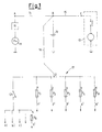
- figure 1 a basic diagram of a typical car system is shown.
- An alternator 11, a battery 12, an electric starter 13 are shown.
- the alternator 11 and the battery 12 are connected by means of a cable 14, indicated by A - B, through which the current from the alternator runs, i.e. the maximum current equal to that of the alternator.
- the length B - C is a large diameter cable 15 through which the current for the starter 13 runs, equal to a few hundred amperes -
- Lengths D - 1, D - 2, ??, D - N are lengths from the branch point D to the corresponding protection fuses shown by F1, F2, ...., FN, which can also be physically contained or integrated, wholly or partly, into a fuse carrier unit.
- system shown in fig. 1 is in reality partly installed in the engine compartment and partly in the dashboard, that is to say in the fuse carrier unit under the dashboard and in the key switch on the steering column.
- the lengths A - B, B - C and B - D,in the engine compartment, are large in diameter, usually 10 + 16 mm2 and so they maintain their assembly positions, therefore if the lay-out and blocking means are chosen correctly, these lengths do not present any problems apart from the need to check their deformation in the case of a frontal collision.
- fuse link As previously mentioned there are protection systems for a part or for all of the live cables by means of fuses, the so called fuse link.
- DE 41 10 240 discloses a protection device, which is able to disconnect electric apparatus of motor vehicles from the supply in case of failure or in case of overload of current that flows in the cables.
- the protection device itself must comprise a great DC remote control switch and a Hall effect device for evaluating the intensity of the current.
- US 3,935,511 discloses a current inrush limiter, in which single or multi-phase AC power is rectified to yield a DC voltage, that is adapted to operate an electrical load.
- a PTC element is inserted in series with the load until a voltage sensitive relay is energized to close its contacts or an SCR is energized to shunt the resistive device out of the circuit.
- the PTC element is only employed for inserting the load and not even for disconnecting said load, so that this current inrush limiter is not able to protect the on-board electrical system of motor vehicles when the electrical contact of the relay (or the electronic contact of the SCR), which is in parallel to the PTC element, is opened.
- the main aim of the present invention is to indicate a device, which gets out of the drawbacks mentioned above, by creating an automatic resetting protection device with almost total coverage both for possible short circuits in the case of a collision of motor vehicles and for those short circuits occurring in any part of the on-board electrical system of motor vehicles, which are perceived as overloads not able to induce the intervention of the corresponding fuses.
- An other object of the present invention is to realize a protection device using a very low number of electrical components relative to the state of the art, which have further small sizes and low costs.
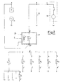
- a live branch B - C carrying a strong current is shown, which is installed and fixed so that it is not affected by any short circuit in the case of a collision.
- a protection device 21, realized according to the invention, and the cable length B - B' are installed and appropriately protected against any frontal collision. Such protective measures depend on the type of engine compartment and its layout.
- the device 21 can be mounted in a place sheltered by the battery 22 or incorporated into the pole itself if such a position is considered sufficiently safe in the possible impact situations.
- a recharging cable A - B'' is connected, downstream from the device 21, for example, to the node B''.
- the system downstream from the node B'' is totally protected by the device 21 as will be described further on, in that it disconnects the whole system downstream from B'' if there is a short-circuit in any section of the live cables.
- the simple disengagement of the key causes the device 21 to limit the short-circuit to far less than 1A, thus preventing any damage to the system or to the soundness of the motor vehicle.
- the device 21 consists of a relay X of which the contact X' is a system sectioning means positioned between point B', which is connected to the positive pole of the battery 22, and point B'' from where all the system starts, and which operates as a branch point in the electrical system of the vehicle.
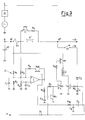
- a shunt Sh is inserted, which can absorb the current of a short circuit.
- a resistance PTC with a positive temperature coefficient and a resistor RO are inserted.
- Said resistance PTC represents a flow path for the current from the battery 22 to the system whenever the contact X' is open. This path, thanks to the inserted PTC, does not allow current, above a set value, to pass. This depends on the type of PTC used; generally a 4A PTC is sufficient.
- the contact X' is open, which, as will be explained further on, can happen either because there has been a short circuit or because the ignition key contact has been opened, the current, due to the effect of an overload in the system downstream, tends to exceed said value, then the PTC, in a time inversely proportionate to said current strength, automatically increases its resistance thus greatly restricting the actual current growth.
- the groups of components R1, R2, R3, R4, C1, C2 consist of voltage dividers and corresponding voltqge filters across the shunt SH.
- a comparator C indicates when a fall in voltage on the shunt Sh and (therefore the current) rises above a determined level, typically 120 + 150A. If this happens, the output of the comparator C reaches high levels.
- the comparator C is equipped with appropriate hysteresis consisting of a group R6, TR5, so that once it has been triggered due to an overload, it memorizes said situation, even if the current is interrupted due to the opening of the contact X' in the relay X. This prevents the cyclic opening and closing of the relay on a short-circuit occurrence.
- the relay X is controlled by an appropriate safety circuit; in fact it is fed from the positive end by means of the transistor TR1 and from the ground end by means of transistor TR2.
- the presence of the key in the ON position is sensed by the circuit D2, C4 which by means of the resistance R9 controls the base of the transistor TR2.
- the transistor TR1 by means of R7, TR3 and R8.
- the presence of the key CH in the ON position results in the energizing of the relay X and the consequent closure of the corresponding contact X'.
- the opening of the key Ch in other words when it is in the OFF position, results in the de-energizing of the relay X and the opening of the contact X'.
- the output of the comparator C determines, through a filter R5, C3, the state, conductivity or non-conductivity, of the transistor TR4 which in turn determines respectively the non-conductivity or conductivity of the transistor TR3, then of TR1 and finally the de-energizing or energizing of the relay X.
- a low ohmic resistance R0 is also shown, the resistance of which has the aim of limiting the momentary peaks of current in the resistance PTC to a value which can be tolerated by the resistance PTC.
- the branch PTC - R0 has different functions which are described hereinafter.
- the branch PTC - R0 must allow the node B'' to receive the battery voltage with the key disengaged, i.e. with the relay X de-energized and with therefore the contact X' open. This allows, on ignition, all the circuits connected to the key Ch to be fed and allows the control panel and all its corresponding functions to be turned on.
- the same branch must furthermore allow the battery 22 to feed all the loads which are required when the key is disengaged.
- these circuits are the electronic systems which provide for RAM memory devices, the electric clocks, the door locking-unlocking remote control units, the car radios, the anti-theft systems, the parking lights with a total constant load of generally less than 4A. Momentary loads, for example door locking operation, will not require the intervention of the PTC.
- an input for emergency lights H is provided for in fig. 3, the input of which can be derived from one of the side lights.
Landscapes
- Emergency Protection Circuit Devices (AREA)
- Charge And Discharge Circuits For Batteries Or The Like (AREA)
- Electric Propulsion And Braking For Vehicles (AREA)
Description
Claims (12)
- An automatic resetting protection device (21) to counter short circuits in the on-board electrical system of motor vehicles, which is inserted between a positive pole (B) of the battery (22) of vehicles and a branch point (B'') of said on-board electrical system, said on-board electrical system comprising an electrical contact of an ignition key (Ch) of the vehicle and a plurality of protection fuses (F1, F2, F3, F4, F5, FN), said protection device (21) also comprising:said contact (X') of the relay (X) is connected in parallel with a little impedance, which is constituted by a resistor (R0) in series to at least one current limitation resistance (PTC), which has a positive temperature coefficient of resistivity, and means (D2,C4,R9,TR2) are provided for de-energizing the relay (X) when said electrical contact of the ignition key (Ch) is in the OFF position, so that, if the contact (X') is open, either because of a short circuit in the on-board electrical system or because the ignition key (Ch) has been disconnected, the current that flows through the on-board electrical system does not exceed a first pre-determined value.a shunt (Sh) for sensing short circuits, which might arise in any section of the cables of said on-board electrical system;voltage dividers (R1, R2, R3, R4, C1, C2,) and corresponding voltage filters at the ends of said shunt (Sh);at least one relay (X), with a contact (X'), which is capable of breaking the connection between said positive pole of the battery (22) and said branch point (B'') of the on-board electrical system, said branch point (B'') also being connected to an alternator (11) of the vehicle;a comparator (C), which is capable of sensing a maximum current and which has a hysteresis to prevent cyclic opening and closure of said relay (X) on said short circuits, characterised in that:
- A protection device (21) according to claim 1, characterised in that said shunt is connected in series to an impedance, which is constituted by said contact (X') of the relay (X) and said little impedance.
- A protection device (21) according to claim 1, characterised in that, in case a part of said on-board electrical system or at least one of said protection fuses (F1, F2, F3, F4, F5, FN) short circuits, due to a value of current lower than the value of current necessary for the intervention of the corresponding fuse, the disengageament of the ignition key (Ch) causes said protection device (21) to limit the short circuit to a value less than 1 Ampere.
- A protection device (21) according to claim 1, characterised in that said current limitation resistance (PTC) allows a value of current equal to or less than 4 Ampere to pass.
- A protection device (21) according to claim 1, characterised in that said first pre-determined value of current is comprised between 120 and 150 Ampere, extreme values included.
- A protection device (21) according to claim 1, characterised in that said hysteresis of the voltage comparator (C) is obtained by means of at least one resistance (R6) and at least one transistor (TR5).
- A protection device (21) according to claim 1, characterised in that said relay (X) is controlled by a safety electric circuit, comprising a plurality of first transistors (TR1, TR2).
- A protection device (21) according to claim 7, characterised in that the closing of said electrical contact of the ignition key (Ch) is sensed by said means for de-energizing, comprising at least one diode (D2) and at least one capacitor (C4), which, by means of a plurality of resistances (R7, R8, R9) and by means of at least one second transistor (TR3), controls said first transistors (TR1, TR2), said contact (X') of the relay (X) being closed so as to energize said relay (X).
- A protection device (21) according to claim 7, characterised in that the opening of said electrical contact of the ignition key (Ch) results in the opening of the contact (X'), so as to protect the on-board electrical system from any overload, from the moment the ignition key (Ch) is removed.
- A protection device (21) according to claim 1, characterised in that said resistor (R0) has a low value of ohmic resistance (R0), in order to limit the momentary peaks of current in said current limitation resistance (PTC).
- A protection device (21) according to claim 7, characterised in that an input (H) for hazard lights is provided, which is connected with said first transistors (TR1, TR2), through at least one diode (D1) and with said relay (X).
- A protection device (21) according to claim 1, characterised in that it is capable of interrupting any short circuit current, in the case of a collision of the motor vehicle.
Applications Claiming Priority (2)
| Application Number | Priority Date | Filing Date | Title |
|---|---|---|---|
| ITTO930478 | 1993-06-30 | ||
| ITTO930478A IT1261067B (en) | 1993-06-30 | 1993-06-30 | AUTOMATIC RESET PROTECTION DEVICE AGAINST SHORT CIRCUITS OF THE ELECTRIC SYSTEM OF THE VEHICLES ON BOARD. |
Publications (2)
| Publication Number | Publication Date |
|---|---|
| EP0632558A1 EP0632558A1 (en) | 1995-01-04 |
| EP0632558B1 true EP0632558B1 (en) | 1998-03-25 |
Family
ID=11411594
Family Applications (1)
| Application Number | Title | Priority Date | Filing Date |
|---|---|---|---|
| EP94106099A Expired - Lifetime EP0632558B1 (en) | 1993-06-30 | 1994-04-20 | Automatic resetting protection device to counter short circuits in the on board electrical system of motor vehicles |
Country Status (3)
| Country | Link |
|---|---|
| EP (1) | EP0632558B1 (en) |
| DE (1) | DE69409166T2 (en) |
| IT (1) | IT1261067B (en) |
Families Citing this family (7)
| Publication number | Priority date | Publication date | Assignee | Title |
|---|---|---|---|---|
| DE19503809B4 (en) * | 1995-02-06 | 2005-01-20 | Bayerische Motoren Werke Ag | Safety device for a power line in vehicles |
| NL1000175C2 (en) * | 1995-04-19 | 1996-10-22 | White Holding B V | Battery clamp. |
| US5936317A (en) * | 1996-04-09 | 1999-08-10 | Harness System Technologies Research, Ltd. | Power supply device for vehicle |
| FR2771225B1 (en) | 1997-11-20 | 1999-12-24 | Bull Sa | PROTECTION AGAINST ELECTRICAL FAULTS IN A DATA STORAGE SYSTEM |
| DE19854953C1 (en) * | 1998-11-27 | 2000-09-21 | Volkswagen Ag | Battery on-board network with safety shutdown |
| JP3441672B2 (en) * | 1999-04-22 | 2003-09-02 | 株式会社オートネットワーク技術研究所 | Automotive power supply monitoring device |
| DE19944833A1 (en) * | 1999-09-18 | 2001-03-22 | Bosch Gmbh Robert | Multi-voltage electrical power |
Family Cites Families (4)
| Publication number | Priority date | Publication date | Assignee | Title |
|---|---|---|---|---|
| US3935511A (en) * | 1973-12-26 | 1976-01-27 | Texas Instruments Incorporated | Current inrush limiter |
| DE3702517A1 (en) * | 1987-01-28 | 1988-08-11 | Mitec Moderne Ind Gmbh | CIRCUIT ARRANGEMENT FOR POWERING A VARIETY OF CONSUMERS |
| GB2228377A (en) * | 1989-01-24 | 1990-08-22 | Peter Alan Kissagizlis | Motor vehicle electrical isolator (emergency) |
| DE4110240C1 (en) * | 1991-03-28 | 1992-10-08 | Mercedes-Benz Aktiengesellschaft, 7000 Stuttgart, De | Vehicle current path protection device - separates battery from load upon occurrence of electrical fault |
-
1993
- 1993-06-30 IT ITTO930478A patent/IT1261067B/en active IP Right Grant
-
1994
- 1994-04-20 EP EP94106099A patent/EP0632558B1/en not_active Expired - Lifetime
- 1994-04-20 DE DE69409166T patent/DE69409166T2/en not_active Expired - Fee Related
Also Published As
| Publication number | Publication date |
|---|---|
| DE69409166T2 (en) | 1998-10-29 |
| ITTO930478A1 (en) | 1994-12-30 |
| ITTO930478A0 (en) | 1993-06-30 |
| IT1261067B (en) | 1996-05-08 |
| DE69409166D1 (en) | 1998-04-30 |
| EP0632558A1 (en) | 1995-01-04 |
Similar Documents
| Publication | Publication Date | Title |
|---|---|---|
| US4611154A (en) | Method and apparatus for controlling the operation of a DC load | |
| DE4110240C1 (en) | Vehicle current path protection device - separates battery from load upon occurrence of electrical fault | |
| US6049140A (en) | Battery disconnection system | |
| KR100851478B1 (en) | Circuit interruption device, safety device for connection in electrical circuit, and method for emhancing safety of electrical circuit | |
| EP1600337B1 (en) | Electronic circuit breaker for battery | |
| US6525918B1 (en) | Adaptive arc fault detection and smart fusing system | |
| US20030080621A1 (en) | Automotive electrical system protection device | |
| US6639389B2 (en) | Arrangement and method for protecting multiple voltage supply systems against voltage arc-over between different voltage planes and against pole reversal from the outside | |
| US20050093371A1 (en) | Automatic battery disconnect system | |
| EP0632558B1 (en) | Automatic resetting protection device to counter short circuits in the on board electrical system of motor vehicles | |
| JPH099491A (en) | Overcurrent protective device of power window circuit board | |
| EP0699563A2 (en) | Electric current distribution system for automotive vehicles | |
| DE10333674B4 (en) | Arc monitoring system in a vehicle electrical system | |
| JP2001508639A (en) | Protective device against incorrect connection in vehicle electrical power supply | |
| JP2001309546A (en) | Protector for vehicle wiring system | |
| WO1995013621A1 (en) | Short circuit protected splice connector | |
| JP3762576B2 (en) | Vehicle power supply device | |
| US6734577B2 (en) | Vehicle auxiliary accessory system | |
| US3152259A (en) | Protective circuit for electrical systems on automotive vehicles | |
| DE102017212156B4 (en) | Electrical supply network and method for operating an electrical supply network | |
| EP0727335B1 (en) | Safety sectioning main switch for automatically sectioning electric loads in motor vehicles and the like | |
| JPS6245476Y2 (en) | ||
| EP2903123B1 (en) | Safety device adapted to be integrated in the electrical circuit of a vehicle | |
| JP4106205B2 (en) | Vehicle power supply device | |
| DE19937491B4 (en) | Safety device for the electrical system of a vehicle |
Legal Events
| Date | Code | Title | Description |
|---|---|---|---|
| PUAI | Public reference made under article 153(3) epc to a published international application that has entered the european phase |
Free format text: ORIGINAL CODE: 0009012 |
|
| AK | Designated contracting states |
Kind code of ref document: A1 Designated state(s): DE ES FR GB SE |
|
| 17P | Request for examination filed |
Effective date: 19950202 |
|
| 17Q | First examination report despatched |
Effective date: 19960226 |
|
| GRAG | Despatch of communication of intention to grant |
Free format text: ORIGINAL CODE: EPIDOS AGRA |
|
| GRAG | Despatch of communication of intention to grant |
Free format text: ORIGINAL CODE: EPIDOS AGRA |
|
| GRAH | Despatch of communication of intention to grant a patent |
Free format text: ORIGINAL CODE: EPIDOS IGRA |
|
| GRAH | Despatch of communication of intention to grant a patent |
Free format text: ORIGINAL CODE: EPIDOS IGRA |
|
| GRAA | (expected) grant |
Free format text: ORIGINAL CODE: 0009210 |
|
| AK | Designated contracting states |
Kind code of ref document: B1 Designated state(s): DE ES FR GB SE |
|
| PG25 | Lapsed in a contracting state [announced via postgrant information from national office to epo] |
Ref country code: ES Free format text: THE PATENT HAS BEEN ANNULLED BY A DECISION OF A NATIONAL AUTHORITY Effective date: 19980325 |
|
| REF | Corresponds to: |
Ref document number: 69409166 Country of ref document: DE Date of ref document: 19980430 |
|
| PG25 | Lapsed in a contracting state [announced via postgrant information from national office to epo] |
Ref country code: SE Free format text: LAPSE BECAUSE OF FAILURE TO SUBMIT A TRANSLATION OF THE DESCRIPTION OR TO PAY THE FEE WITHIN THE PRESCRIBED TIME-LIMIT Effective date: 19980625 |
|
| ET | Fr: translation filed | ||
| PLBE | No opposition filed within time limit |
Free format text: ORIGINAL CODE: 0009261 |
|
| STAA | Information on the status of an ep patent application or granted ep patent |
Free format text: STATUS: NO OPPOSITION FILED WITHIN TIME LIMIT |
|
| 26N | No opposition filed | ||
| REG | Reference to a national code |
Ref country code: GB Ref legal event code: IF02 |
|
| PGFP | Annual fee paid to national office [announced via postgrant information from national office to epo] |
Ref country code: FR Payment date: 20080312 Year of fee payment: 15 Ref country code: DE Payment date: 20080424 Year of fee payment: 15 |
|
| PGFP | Annual fee paid to national office [announced via postgrant information from national office to epo] |
Ref country code: GB Payment date: 20080423 Year of fee payment: 15 |
|
| GBPC | Gb: european patent ceased through non-payment of renewal fee |
Effective date: 20090420 |
|
| REG | Reference to a national code |
Ref country code: FR Ref legal event code: ST Effective date: 20091231 |
|
| PG25 | Lapsed in a contracting state [announced via postgrant information from national office to epo] |
Ref country code: DE Free format text: LAPSE BECAUSE OF NON-PAYMENT OF DUE FEES Effective date: 20091103 |
|
| PG25 | Lapsed in a contracting state [announced via postgrant information from national office to epo] |
Ref country code: GB Free format text: LAPSE BECAUSE OF NON-PAYMENT OF DUE FEES Effective date: 20090420 Ref country code: FR Free format text: LAPSE BECAUSE OF NON-PAYMENT OF DUE FEES Effective date: 20091222 |