EP0632286A2 - Self-calibrating, eigenstructure based method and means of direction finding - Google Patents
Self-calibrating, eigenstructure based method and means of direction finding Download PDFInfo
- Publication number
- EP0632286A2 EP0632286A2 EP94303069A EP94303069A EP0632286A2 EP 0632286 A2 EP0632286 A2 EP 0632286A2 EP 94303069 A EP94303069 A EP 94303069A EP 94303069 A EP94303069 A EP 94303069A EP 0632286 A2 EP0632286 A2 EP 0632286A2
- Authority
- EP
- European Patent Office
- Prior art keywords
- gain
- directions
- radiation
- sources
- array
- Prior art date
- Legal status (The legal status is an assumption and is not a legal conclusion. Google has not performed a legal analysis and makes no representation as to the accuracy of the status listed.)
- Granted
Links
Images

Classifications
-
- G—PHYSICS
- G01—MEASURING; TESTING
- G01S—RADIO DIRECTION-FINDING; RADIO NAVIGATION; DETERMINING DISTANCE OR VELOCITY BY USE OF RADIO WAVES; LOCATING OR PRESENCE-DETECTING BY USE OF THE REFLECTION OR RERADIATION OF RADIO WAVES; ANALOGOUS ARRANGEMENTS USING OTHER WAVES
- G01S7/00—Details of systems according to groups G01S13/00, G01S15/00, G01S17/00
- G01S7/02—Details of systems according to groups G01S13/00, G01S15/00, G01S17/00 of systems according to group G01S13/00
- G01S7/36—Means for anti-jamming, e.g. ECCM, i.e. electronic counter-counter measures
-
- G—PHYSICS
- G01—MEASURING; TESTING
- G01S—RADIO DIRECTION-FINDING; RADIO NAVIGATION; DETERMINING DISTANCE OR VELOCITY BY USE OF RADIO WAVES; LOCATING OR PRESENCE-DETECTING BY USE OF THE REFLECTION OR RERADIATION OF RADIO WAVES; ANALOGOUS ARRANGEMENTS USING OTHER WAVES
- G01S3/00—Direction-finders for determining the direction from which infrasonic, sonic, ultrasonic, or electromagnetic waves, or particle emission, not having a directional significance, are being received
- G01S3/02—Direction-finders for determining the direction from which infrasonic, sonic, ultrasonic, or electromagnetic waves, or particle emission, not having a directional significance, are being received using radio waves
- G01S3/023—Monitoring or calibrating
-
- G—PHYSICS
- G01—MEASURING; TESTING
- G01S—RADIO DIRECTION-FINDING; RADIO NAVIGATION; DETERMINING DISTANCE OR VELOCITY BY USE OF RADIO WAVES; LOCATING OR PRESENCE-DETECTING BY USE OF THE REFLECTION OR RERADIATION OF RADIO WAVES; ANALOGOUS ARRANGEMENTS USING OTHER WAVES
- G01S3/00—Direction-finders for determining the direction from which infrasonic, sonic, ultrasonic, or electromagnetic waves, or particle emission, not having a directional significance, are being received
- G01S3/02—Direction-finders for determining the direction from which infrasonic, sonic, ultrasonic, or electromagnetic waves, or particle emission, not having a directional significance, are being received using radio waves
- G01S3/74—Multi-channel systems specially adapted for direction-finding, i.e. having a single antenna system capable of giving simultaneous indications of the directions of different signals
Definitions
- the present invention relates generally to a method and means of radar signal processing for direction finding purposes, and, more particularly, to such a method and means especially advantageous for use with a radar target seeker.
- a radar seeker operates generally by emitting radar beam pulses toward a target, measuring the time traveled by pulses reflected from the target and adjusting the radar beam for maximum response, which enables both the direction and distance of the target to be determined.
- Direction-finding techniques based upon eigenstructure methods have been proposed and experimentally verified and have shown themselves to be superior to conventional direction-finding equipment for overcoming standard defensive measures.
- Application of eigenstructure techniques requires a radar system having an active antenna array, that is, a plurality of antennae arranged in a matrix for sending and receiving radar pulses over a relatively large area including a sought after target and which antennae are controllable as to phase and gain.
- Another object is the provision of means and method in accordance with the previous object by which a given target can be readily resolved from among relatively closely spaced multiple targets.
- Yet another object is the provision in the above-identified objects of a method and means utilizing an active array radar seeker which does not require initial sensor array calibration or maintaining precise sensor calibration.
- the described method includes receiving radiation from one or more radiating sources in a monitored region by the antenna array. With selected nominal gain and phase values for each antenna element of the array, a first estimate of directions of the radiating sources with respect to the array is calculated in a microprocessor by the use of an algorithm referred to as MUSIC. Updating of the gain and phase for each antenna element is accomplished by signals received by the array. Iterations of direction estimates are made based upon this and further updated gain and phase values until that iteration is reached which produces the maximum difference value of the smallest eigenvalue pair of
- a typical radar seeker system 10 including generally a source 12 of high frequency pulses 13 which are fed through a so-called duplexer 14 to an antenna 16 where they are radiated toward a target 18. These pulses 13 are reflected off the target and return to the antenna 16.
- the duplexer 14 is essentially a switch that enables common use of one antenna for both transmitting and receiving reflected pulses which are then sent on to the receiver 20 for processing and display. By noting antenna orientation for maximum strength pulse reception and the time for pulse transmission, both the direction and distance to a target 18 can be determined.
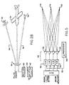
- FIG. 2A depicts the camouflaging effect that is produced when a large number of foil pieces 22 ("window") are released in the vicinity of a target aircraft 24.
- a plurality of pulse echoes are received from the target 24 as well as foil pieces 28,28' which serves to hide or make it difficult to locate the target within the many false echoes produced by the individual pieces of foil as seen on a display 30, for example.
- FIG. 2B depicts another defensive technique used against a seeker in which several target escort craft 32 and 34 each emit separate radar waves 36 and 38, respectively, directed toward the seeker antenna 16. These radar waves are of proper frequency and produce readily detectable signals 40 and 42 in the seeker receiver which can be easily confused with the echo signal 44 from the true target 24.
- an active antenna array enumerated generally as 46 which is especially useful with a seeker operating on an eigenstructure basis as the present invention does. More particularly, the active array is seen to include a plurality of individual antenna elements 48 with corresponding individual transmission and receive (T/R) controls 50 which can be controlled by lines 52 to detect or selectively modify the gain and phase of each of the antenna elements.
- a microprocessor 54 is appropriately programmed to cause the active array 46 to be selectively modified in a manner to be described to determine the actual target from among the various signal radiation sources 56,58,60 -- that the system may be receiving, including defensively produced radar beams, for example.
- Such an active antenna array is to be found more particularly described in copending patent application AN ACTIVE ANTENNA ARRAY, Serial No. by J. Conrad et al. assigned to the same assignee as the present application.
- an eigenstructure method for direction finding in the presence of sensor gain and phase uncertainties.
- This method requires a minimum of two radiation sources for use (e.g., a target and one false echo) and, therefore, excludes applicability to single-source encounters which are a most frequent occurrence.
- this method requires a subjectively preselected threshold to terminate iteration. This latter feature makes it difficult to optimize performance since in certain cases the process does not converge to the correct result. For example, in the situation where there are several closely spaced radiation sources and a low preselected threshold, the algorithm may not be resolvable.
- T and + represent the transpose and complex conjugate transpose, respectively and E[.] is the expectation operator
- the MUSIC spatial spectrum estimator given by produces the K-highest spectral peaks at the different angles of arrivale ⁇ 1, ⁇ 2, ..., ⁇ K if the sensor gains and phases are known. In practice, however, we only know the sensor gains and phases approximately within some specified manufacturing-tolerance limits. As a consequence, the resolution performance of the MUSIC algorithm can be severely degraded and may not provide spectral peaks for all angles of arrival.
- the difference in d values tells whether rank ( Q ⁇ ) is (M-1) or not. If rank ( Q ⁇ ) ⁇ M-1, the difference in d values is zero whereas the maximum value of the difference value insure that rank ( Q ⁇ ) is at least M-1. Accordingly, iteration continues until the indicated difference in d values reaches its maximum.
- the described algorithm proceeds in a microprocessor. At each iteration, the angle/gain/phase estimates are updated and utilized for the next iteration until the process is terminated. After termination, the calculated final angle estimates from MUSIC are utilized for the tracking system, and the final gain/phase estimates are applied to a new set of array measurements as the new on-board, calibrated data.
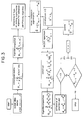
- FIG. 3 depicts a flow block diagram of the described method of this invention.
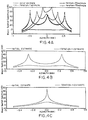
- FIG. 4A shows the results obtained when the method of this invention is applied to a three-source scene.
- FIG. 4B shows results obtained for a two-source scene
- FIG. 4C is a single-source scene.
- the present method can be applied to single-source scene whereas the Weiss and Friedlander technique referenced earlier cannot, since that would require calculation of Q ⁇ 1.
- the advantage of a seeker being able to handle the single radiation source situation has alrady been discussed.
Abstract
Description
- The present invention relates generally to a method and means of radar signal processing for direction finding purposes, and, more particularly, to such a method and means especially advantageous for use with a radar target seeker.
- A radar seeker operates generally by emitting radar beam pulses toward a target, measuring the time traveled by pulses reflected from the target and adjusting the radar beam for maximum response, which enables both the direction and distance of the target to be determined.
- In the usual situation, there may be other objects adjacent the sought after target which will produce radar reflections and, in that way, induce confusion and error into the tracking system. Also, in a military context defensive measures are taken to intentionally interfere with the operation and accuracy of a radar seeker aboard, say, an aircraft. For example, large quantities of radar reflecting foil strips ("window") dropped in the vicinity of a flying target aircraft can effectively block out radar detection of the craft. Another frequently employed radar camouflaging technique for an aircraft consists of having one or more escort craft flying near the target aircraft which direct "jamming" radar beams of appropriate frequency toward the search radar source to confuse and induce spurious direction information into the search tracking system.
- Direction-finding techniques based upon eigenstructure methods have been proposed and experimentally verified and have shown themselves to be superior to conventional direction-finding equipment for overcoming standard defensive measures. Application of eigenstructure techniques requires a radar system having an active antenna array, that is, a plurality of antennae arranged in a matrix for sending and receiving radar pulses over a relatively large area including a sought after target and which antennae are controllable as to phase and gain.
- A more detailed discussion of a prior eigenstructure method can be found in the article, "Eigenstructure Methods for Direction Finding with Sensor Gain and Phase Uncertainties", by Anthony J. Weiss and Benjamin Friedlander, Proceedings IEEE, ICASSP 198, New York, New York. This technique requires at least two sources (i,e., two reflected radar signals) for proper operation which excludes applicability to a very frequently encountered situation, namely, a single-source encounter. Moreover, in this and in all known prior eigenstructure techniques precise knowledge of signals received by the sensor array is required which, in turn, requires initial calibration of the entire seeker data collection system, a time consuming and difficult task. Still further, there is the necessity for maintaining array calibration in these known systems which is additionally difficult and time consuming.
- It is a primary aim and object of the present invention to provide a radar direction finding means and method capable of satisfactory operation with radar return signals being imprecisely sensed as to both gain and phase.
- Another object is the provision of means and method in accordance with the previous object by which a given target can be readily resolved from among relatively closely spaced multiple targets.
- Yet another object is the provision in the above-identified objects of a method and means utilizing an active array radar seeker which does not require initial sensor array calibration or maintaining precise sensor calibration.
- The described method includes receiving radiation from one or more radiating sources in a monitored region by the antenna array. With selected nominal gain and phase values for each antenna element of the array, a first estimate of directions of the radiating sources with respect to the array is calculated in a microprocessor by the use of an algorithm referred to as MUSIC. Updating of the gain and phase for each antenna element is accomplished by signals received by the array. Iterations of direction estimates are made based upon this and further updated gain and phase values until that iteration is reached which produces the maximum difference value of the smallest eigenvalue pair of

-
- FIG. 1 is a schematic depiction of a conventional radar seeker;
- FIGS. 2A and 2B show typical defensive techniques presently used against a radar seeker;
- FIG. 3 is a function block flow diagram of the described method;
- FIGS. 4A, 4B and 4C are graphs of results obtained in practicing the described method for three-source, two-source and one-source scenes, respectively; and
- FIG. 5 is a schematic of a radar system for practicing the method of this invention.
- With reference now to FIG. 1 of the drawing, a typical
radar seeker system 10 is shown including generally a source 12 ofhigh frequency pulses 13 which are fed through a so-calledduplexer 14 to anantenna 16 where they are radiated toward atarget 18. Thesepulses 13 are reflected off the target and return to theantenna 16. Theduplexer 14 is essentially a switch that enables common use of one antenna for both transmitting and receiving reflected pulses which are then sent on to thereceiver 20 for processing and display. By noting antenna orientation for maximum strength pulse reception and the time for pulse transmission, both the direction and distance to atarget 18 can be determined. - FIG. 2A depicts the camouflaging effect that is produced when a large number of foil pieces 22 ("window") are released in the vicinity of a
target aircraft 24. As shown, a plurality of pulse echoes are received from thetarget 24 as well asfoil pieces 28,28' which serves to hide or make it difficult to locate the target within the many false echoes produced by the individual pieces of foil as seen on adisplay 30, for example. - FIG. 2B depicts another defensive technique used against a seeker in which several
target escort craft separate radar waves seeker antenna 16. These radar waves are of proper frequency and produce readilydetectable signals echo signal 44 from thetrue target 24. - A seeker having a single element antenna or fixed array antenna, such as the
antenna 16 in FIG. 1, merely receives all signals and echoes directed tovard it and forwards the signals for processing and display. As has just been illustrated this can result in a composite set of signal displays resulting from both the actual target and other spurious targets located at a considerable spacing from the actual target and homing in on the wrong target. A seeker of this kind is not able to distinguish a very broad range of radar returns and separate defensive radar beams from true target returns. - With reference now to FIG. 3, there is shown partially in schematic form an active antenna array enumerated generally as 46 which is especially useful with a seeker operating on an eigenstructure basis as the present invention does. More particularly, the active array is seen to include a plurality of
individual antenna elements 48 with corresponding individual transmission and receive (T/R)controls 50 which can be controlled bylines 52 to detect or selectively modify the gain and phase of each of the antenna elements. Amicroprocessor 54 is appropriately programmed to cause theactive array 46 to be selectively modified in a manner to be described to determine the actual target from among the varioussignal radiation sources - In the referenced Weiss et al. article an eigenstructure method is provided for direction finding in the presence of sensor gain and phase uncertainties. This method requires a minimum of two radiation sources for use (e.g., a target and one false echo) and, therefore, excludes applicability to single-source encounters which are a most frequent occurrence. Also, this method requires a subjectively preselected threshold to terminate iteration. This latter feature makes it difficult to optimize performance since in certain cases the process does not converge to the correct result. For example, in the situation where there are several closely spaced radiation sources and a low preselected threshold, the algorithm may not be resolvable.
- Before proceeding with the description of the present invention, development of estimates by the so-called MUSIC algorithm for K observable radiating sources by an array of M antenna elements will be set forth and it is submitted will be of assistance in understanding the advantages of the invention. A detailed description of this technique can be found in PRIMARY SIGNAL PROCESSING, S.U. Pillai, Springer Verlag (1989). Initially, the M x 1 output data vector of the array can be described by x(t)=G A s(t) + n(t) where
G = diag[g₁,g₂,...,gM] : MxM diagonal matrix
gi (ε complex) : the unknown gain and phase of the i-th sensor
M x K matrix with unknown ϑ₁, ϑ₂, ..., ϑK
a (ϑk): M x 1 direction vector of the k-th source
s(t) : K x 1 complex Gaussian signal vector with
n(t) :M X 1 complex Gaussian noise vector, independent of s(t), with
(The superscripts T and + represent the transpose and complex conjugate transpose, respectively and E[.] is the expectation operator.) - The covariance matrix of x(t) is given by

where λi,ei;i=1,2,...,M are the eigenvalues and eigenvectors of Rx. With rank(Rs)=K (i.e., K sources are not fully correlated), we have
where
EN = [eK+1,...,eM]: Mx(M-K)noise-subspace eigenmatrix
Ã(ϑk) = diag (a(ϑk)):MxM diagonal matrix with elements of a(ϑk)
g = [g₁,..., gM]T:M x 1 vector. - The MUSIC spatial spectrum estimator, given by

produces the K-highest spectral peaks at the different angles of arrivale ϑ₁, ϑ₂, ..., ϑK if the sensor gains and phases are known. In practice, however, we only know the sensor gains and phases approximately within some specified manufacturing-tolerance limits. As a consequence, the resolution performance of the MUSIC algorithm can be severely degraded and may not provide spectral peaks for all angles of arrival. - In order to substantially reduce the effects of sensor-channel gain and phase uncertainties, the method of this invention was developed arising out of the following theorem.
- Given an error-free estimate of ÊN (i.e., ÊN = EN) and

define
- Then, there exists a unique g, where

and VM is the eigenvector corresponding to the smallest eigenvalue of Q, if
(Λ represents the estimate from the finite-sample data vectors). - At this time it is believed presentation of a proof of the above theorem would be of assistance in understanding the invention. By the hermitian structure of Q and the orthogonality property stated in (1), we have

which implies
Assuming that rank (Q) = M'(≦ M-2) and
by eigendecomposition, then
and g can be expressed as a linear combination of VM'+1, VM'+2, ..., VM, i.e.,
Thus, to have a unique solution for g, M' = M - 1. The disclosed technique starts with nominal gain and phase values and estimate

a new estimate of g is obtained by (3) and (4). - As initial condition for practice of the invention, set i = 0 and g(i) = g₀, where go can be based on the nominal gains and phase values, or on any recent calibration data. In the usual situation,a nominal g is selected to be recent calibrated gain and phase values among "off-board" and "on-board" data. Then, by application of MUSIC, values for ϑ(i), ϑ


Construct
and compute d(i)= σ


(σ


If d(i-1) - d(i) ≦ 0, then i = i+1 and you proceed by updating g(i) with the eigenvector corresponding to the smallest eigenvalue of Q(i) namely, g(i) = V
- As to practical accomplishment of the method, with initial g selected from the most recent calibration gain and phase values and a set of measurements from an active array, the described algorithm proceeds in a microprocessor. At each iteration, the angle/gain/phase estimates are updated and utilized for the next iteration until the process is terminated. After termination, the calculated final angle estimates from MUSIC are utilized for the tracking system, and the final gain/phase estimates are applied to a new set of array measurements as the new on-board, calibrated data.
- FIG. 3 depicts a flow block diagram of the described method of this invention. FIG. 4A shows the results obtained when the method of this invention is applied to a three-source scene. Similarly, FIG. 4B shows results obtained for a two-source scene, and FIG. 4C is a single-source scene.
- As already alluded to, the present method can be applied to single-source scene whereas the Weiss and Friedlander technique referenced earlier cannot, since that would require calculation of Q⁻¹. The advantage of a seeker being able to handle the single radiation source situation has alrady been discussed.
- Although the invention has been described in connection with a preferred embodiment, it is to be understood that those skilled in the appertaining arts may make changes which come within the spirit of the disclosure and ambit of the appended claims.
Claims (8)
- A method of determining the individual directions of separate radiating sources in a region, comprising:
directing a plurality of radiation sensing elements formed into an array toward the region;
selecting initial nominal gain and phase values for the elements;
measuring the individual element gain and phase values of radiation received from the radiating sources by the antenna array;
calculating first estimation peaks of directions of arrival of radiation from the sources to the antenna arrays;
updating the gain and phase values;
iteratively calculating further estimation peaks of directions of radiation arrival from the sources based upon further updated gain and phase values; and
terminating iterative estimation calculations. - A method as in claim 1, in which the selected nominal gain and phase values are recent calibrated values.
- A method as in claim 1, in which the selected nominal gain and phase values are the final gain and phase value estimates of an immediately preceding determination of directions of radiating sources.
- A method as in claim 1, in which updating in any iteration includes adopting the most recent gain and phase value measurements.
- A method as in claim 1, in which estimates of K radiating sources directions are obtained by solution of the algorithm

- A method as in claim 4, in which termination is determined by constructing

- Means for ascertaining respective directions of one or more radiating sources, comprising:
an array including a plurality radiation sensors oriented to receive radiation from the sources;
means interconnected with each of said radiation sensors for measuring gain and phase values; and
a microprocessor interconnected with said measuring means and programmed to iteratively calculate estimation peaks of directions of radiation received from the source, construct
- Means as in claim 6, in which the estimated peaks for K radiating and an array of M sensors are obtained by solving

Applications Claiming Priority (2)
| Application Number | Priority Date | Filing Date | Title |
|---|---|---|---|
| US08/054,177 US5525997A (en) | 1993-04-30 | 1993-04-30 | Self-calibrating, eigenstructure based method and means of direction finding |
| US54177 | 1998-04-02 |
Publications (3)
| Publication Number | Publication Date |
|---|---|
| EP0632286A2 true EP0632286A2 (en) | 1995-01-04 |
| EP0632286A3 EP0632286A3 (en) | 1995-07-05 |
| EP0632286B1 EP0632286B1 (en) | 1998-12-23 |
Family
ID=21989260
Family Applications (1)
| Application Number | Title | Priority Date | Filing Date |
|---|---|---|---|
| EP94303069A Expired - Lifetime EP0632286B1 (en) | 1993-04-30 | 1994-04-28 | Self-calibrating, eigenstructure based method and means of direction finding |
Country Status (9)
| Country | Link |
|---|---|
| US (1) | US5525997A (en) |
| EP (1) | EP0632286B1 (en) |
| JP (1) | JP2695614B2 (en) |
| KR (1) | KR0132753B1 (en) |
| CA (1) | CA2122403A1 (en) |
| DE (1) | DE69415417T2 (en) |
| ES (1) | ES2125407T3 (en) |
| IL (1) | IL109472A (en) |
| NO (1) | NO941563L (en) |
Cited By (6)
| Publication number | Priority date | Publication date | Assignee | Title |
|---|---|---|---|---|
| EP0687921A1 (en) * | 1994-06-16 | 1995-12-20 | Alcatel N.V. | Method and system of localisation of ground transmitters using satellites |
| GB2347036A (en) * | 1999-01-06 | 2000-08-23 | Nec Corp | Estimating arrival direction of a repeatedly transmitted signal, using cross-correlation |
| EP1215507A2 (en) * | 2000-12-12 | 2002-06-19 | Matsushita Electric Industrial Co., Ltd. | Radio-wave arrival-direction estimating apparatus and directional variable transceiver |
| US6549762B1 (en) | 1999-01-06 | 2003-04-15 | Nec Corporation | Method for estimating arrival direction of desired wave |
| RU2497141C1 (en) * | 2012-06-29 | 2013-10-27 | Федеральное государственное бюджетное образовательное учреждение высшего профессионального образования "Московский государственный технический университет имени Н.Э. Баумана" (МГТУ им. Н.Э. Баумана) | Method for multi-signal direction-finding of radio sources at same frequency for circular antenna system |
| CN110334638A (en) * | 2019-06-28 | 2019-10-15 | 西安理工大学 | Road double amber lines detection method based on quick MUSIC algorithm |
Families Citing this family (15)
| Publication number | Priority date | Publication date | Assignee | Title |
|---|---|---|---|---|
| US5999800A (en) * | 1996-04-18 | 1999-12-07 | Korea Telecom Freetel Co., Ltd. | Design technique of an array antenna, and telecommunication system and method utilizing the array antenna |
| JP3449457B2 (en) * | 1996-04-18 | 2003-09-22 | 勝元 崔 | Signal processing apparatus and method for minimizing interference and reducing noise in a wireless communication system |
| KR100229094B1 (en) * | 1996-06-28 | 1999-11-01 | 최승원 | Signal processing method of array antenna using eigenvector corresponding to maximum eigen value |
| US5943013A (en) * | 1997-09-29 | 1999-08-24 | Mitsubishi Denki Kabushiki Kaisha | Direction finder |
| DE19753932A1 (en) * | 1997-12-05 | 1999-06-10 | Cit Alcatel | Method for determining the direction of reception by means of a group antenna, base station and radio system |
| US6437741B1 (en) | 2001-01-10 | 2002-08-20 | Itt Manufacturing Enterprises, Inc. | Detection of emissions from commercial electronic devices that include an amplitude modulation component |
| JP4498269B2 (en) * | 2005-11-30 | 2010-07-07 | 株式会社デンソーアイティーラボラトリ | Radar signal processing device |
| US7535408B2 (en) * | 2007-08-31 | 2009-05-19 | Lockheed Martin Corporation | Apparatus and methods for detection of multiple targets within radar resolution cell |
| JP4954112B2 (en) * | 2008-02-18 | 2012-06-13 | 三菱電機株式会社 | Array angle measuring device |
| JP5628732B2 (en) * | 2011-04-04 | 2014-11-19 | 富士通テン株式会社 | Arithmetic apparatus for radar apparatus, radar apparatus, arithmetic method and program for radar apparatus |
| JP2013096908A (en) * | 2011-11-02 | 2013-05-20 | Honda Elesys Co Ltd | Radar apparatus for on-vehicle use, method for on-vehicle radar operation, and program for on-vehicle radar operation |
| JP2014002053A (en) | 2012-06-19 | 2014-01-09 | Honda Elesys Co Ltd | On-vehicle rader system, on-vehicle radar method and on-vehicle radar program |
| FR3047568B1 (en) | 2016-02-05 | 2018-02-16 | Thales | METHOD OF CALIBRATING A SATELLITE RADIO NAVIGATION RECEIVER |
| US11460558B2 (en) | 2017-07-20 | 2022-10-04 | UNIVERSITé LAVAL | Second-order detection method and system for optical ranging applications |
| CN114200390B (en) * | 2022-02-17 | 2022-05-13 | 中国人民解放军空军预警学院 | Space spectrum estimation-based passive radar seeker two-dimensional direction finding method and device |
Citations (2)
| Publication number | Priority date | Publication date | Assignee | Title |
|---|---|---|---|---|
| US4947176A (en) * | 1988-06-10 | 1990-08-07 | Mitsubishi Denki Kabushiki Kaisha | Multiple-beam antenna system |
| US5049890A (en) * | 1974-09-23 | 1991-09-17 | The United States Of America As Represented By The Secretary Of The Navy | Sampled data processing |
Family Cites Families (7)
| Publication number | Priority date | Publication date | Assignee | Title |
|---|---|---|---|---|
| US4316191A (en) * | 1980-04-14 | 1982-02-16 | The Bendix Corporation | Low angle radar processing means |
| US5027127A (en) * | 1985-10-10 | 1991-06-25 | United Technologies Corporation | Phase alignment of electronically scanned antenna arrays |
| US4783744A (en) * | 1986-12-08 | 1988-11-08 | General Dynamics, Pomona Division | Self-adaptive IRU correction loop design interfacing with the target state estimator for multi-mode terminal handoff |
| US5056051A (en) * | 1989-06-06 | 1991-10-08 | Technology For Communications International | Signal direction finding processor using fast Fourier transforms for receiver matching |
| US5068597A (en) * | 1989-10-30 | 1991-11-26 | General Electric Company | Spectral estimation utilizing a minimum free energy method with recursive reflection coefficients |
| US5063529A (en) * | 1989-12-29 | 1991-11-05 | Texas Instruments Incorporated | Method for calibrating a phased array antenna |
| US5223841A (en) * | 1992-06-29 | 1993-06-29 | The United States Of America As Represented By The Secretary Of The Navy | Calibration method and apparatus for collecting the output of an array of detector cells |
-
1993
- 1993-04-30 US US08/054,177 patent/US5525997A/en not_active Expired - Lifetime
-
1994
- 1994-04-28 EP EP94303069A patent/EP0632286B1/en not_active Expired - Lifetime
- 1994-04-28 IL IL109472A patent/IL109472A/en not_active IP Right Cessation
- 1994-04-28 CA CA002122403A patent/CA2122403A1/en not_active Abandoned
- 1994-04-28 DE DE69415417T patent/DE69415417T2/en not_active Expired - Lifetime
- 1994-04-28 NO NO941563A patent/NO941563L/en unknown
- 1994-04-28 ES ES94303069T patent/ES2125407T3/en not_active Expired - Lifetime
- 1994-04-30 KR KR1019940009522A patent/KR0132753B1/en active IP Right Grant
- 1994-05-02 JP JP6093582A patent/JP2695614B2/en not_active Expired - Fee Related
Patent Citations (2)
| Publication number | Priority date | Publication date | Assignee | Title |
|---|---|---|---|---|
| US5049890A (en) * | 1974-09-23 | 1991-09-17 | The United States Of America As Represented By The Secretary Of The Navy | Sampled data processing |
| US4947176A (en) * | 1988-06-10 | 1990-08-07 | Mitsubishi Denki Kabushiki Kaisha | Multiple-beam antenna system |
Non-Patent Citations (2)
| Title |
|---|
| ICAASP '88, vol. 5, 11 April 1988 - 14 April 1988 NEW YORK US, pages 2681-2684, FRIEDLANDER ET AL. 'EIGENSTRUCTURE METHODS FOR DIRECTION FINDING WITH SENSOR GAIN AND PHASE UNCERTAINTIES' * |
| MILITARY COMMUNICATIONS IN A CHANGING WORLD, vol. 3, 4 November 1991 - 7 November 1991 MCLEAN, VA., pages 943-947, XP 000273838 KOWALSKI ET AL 'MUSIC ALGORITHM IMPLEMENTATION FOR SHIP BOARD HF RADIO DIRECTION FINDING' * |
Cited By (17)
| Publication number | Priority date | Publication date | Assignee | Title |
|---|---|---|---|---|
| FR2721410A1 (en) * | 1994-06-16 | 1995-12-22 | Alcatel Espace | Ground Transmitter Locator for Satellites |
| US5859610A (en) * | 1994-06-16 | 1999-01-12 | Alcatel N.V. | Method and a system for locating ground equipment transmitting via satellites |
| EP0687921A1 (en) * | 1994-06-16 | 1995-12-20 | Alcatel N.V. | Method and system of localisation of ground transmitters using satellites |
| US6549762B1 (en) | 1999-01-06 | 2003-04-15 | Nec Corporation | Method for estimating arrival direction of desired wave |
| GB2347036A (en) * | 1999-01-06 | 2000-08-23 | Nec Corp | Estimating arrival direction of a repeatedly transmitted signal, using cross-correlation |
| GB2347036B (en) * | 1999-01-06 | 2003-09-10 | Nec Corp | Method for estimating arrival direction of desired wave |
| US6642888B2 (en) | 2000-12-12 | 2003-11-04 | Matsushita Electric Industrial Co., Ltd. | Radio-wave arrival-direction estimating apparatus and directional variable transceiver |
| EP1215507A3 (en) * | 2000-12-12 | 2002-08-28 | Matsushita Electric Industrial Co., Ltd. | Radio-wave arrival-direction estimating apparatus and directional variable transceiver |
| EP1215507A2 (en) * | 2000-12-12 | 2002-06-19 | Matsushita Electric Industrial Co., Ltd. | Radio-wave arrival-direction estimating apparatus and directional variable transceiver |
| EP1387181A1 (en) * | 2000-12-12 | 2004-02-04 | Matsushita Electric Industrial Co., Ltd. | Radio-wave arrival-direction estimating apparatus and directional variable transceiver |
| EP1387180A1 (en) * | 2000-12-12 | 2004-02-04 | Matsushita Electric Industrial Co., Ltd. | Radio-wave arrival-direction estimating apparatus and directional variable transceiver |
| EP1398645A1 (en) * | 2000-12-12 | 2004-03-17 | Matsushita Electric Industrial Co., Ltd. | Radio-wave arrival-direction estimating apparatus and directional variable transceiver |
| US6836245B2 (en) | 2000-12-12 | 2004-12-28 | Matsushita Electric Industrial Co., Ltd. | Radio-wave arrival-direction estimating apparatus and directional variable transceiver |
| US6897807B2 (en) | 2000-12-12 | 2005-05-24 | Matsushita Electric Industrial Co., Ltd. | Radio-wave arrival-direction estimating apparatus and directional variable transceiver |
| RU2497141C1 (en) * | 2012-06-29 | 2013-10-27 | Федеральное государственное бюджетное образовательное учреждение высшего профессионального образования "Московский государственный технический университет имени Н.Э. Баумана" (МГТУ им. Н.Э. Баумана) | Method for multi-signal direction-finding of radio sources at same frequency for circular antenna system |
| CN110334638A (en) * | 2019-06-28 | 2019-10-15 | 西安理工大学 | Road double amber lines detection method based on quick MUSIC algorithm |
| CN110334638B (en) * | 2019-06-28 | 2021-09-10 | 西安理工大学 | Road double yellow line detection method based on rapid MUSIC algorithm |
Also Published As
| Publication number | Publication date |
|---|---|
| NO941563D0 (en) | 1994-04-28 |
| EP0632286A3 (en) | 1995-07-05 |
| ES2125407T3 (en) | 1999-03-01 |
| KR0132753B1 (en) | 1998-10-01 |
| EP0632286B1 (en) | 1998-12-23 |
| IL109472A (en) | 1997-07-13 |
| US5525997A (en) | 1996-06-11 |
| CA2122403A1 (en) | 1994-10-31 |
| NO941563L (en) | 1994-10-31 |
| DE69415417T2 (en) | 1999-05-12 |
| DE69415417D1 (en) | 1999-02-04 |
| JP2695614B2 (en) | 1998-01-14 |
| JPH07140226A (en) | 1995-06-02 |
Similar Documents
| Publication | Publication Date | Title |
|---|---|---|
| EP0632286B1 (en) | Self-calibrating, eigenstructure based method and means of direction finding | |
| US5392050A (en) | Method of recognizing a radar target object type and apparatus therefor | |
| US6661366B2 (en) | Adaptive digital sub-array beamforming and deterministic sum and difference beamforming, with jamming cancellation and monopulse ratio preservation | |
| US6995705B2 (en) | System and method for doppler track correlation for debris tracking | |
| CN109407093B (en) | Doppler measurement for resolving ambiguity of angle of arrival of wide aperture radar | |
| US6697009B2 (en) | Adaptive digital beamforming architecture for target detection and angle estimation in multiple mainlobe and sidelobe jamming | |
| US4675677A (en) | Method and system for detecting and combating covered ground targets | |
| US6404379B1 (en) | Matrix monopulse ratio radar processor for two target azimuth and elevation angle determination | |
| US6411249B1 (en) | Apparatus and method for the monopulse linking of frequency agile emitter pulses intercepted in on single interferometer baseline | |
| US20030071749A1 (en) | Digital beamforming for passive detection of target using reflected jamming echoes | |
| EP1286180B1 (en) | Periodic repetition interval staggered post-doppler adaptive monopulse processing for detection and location of a moving target in ground clutter | |
| US5615175A (en) | Passive direction finding device | |
| EP3019888A1 (en) | Interference nulling of multipath signals in stacked beam pulse radar | |
| US20200003868A1 (en) | Method of determining an alignment error of an antenna and vehicle with an antenna and a detection device | |
| US20030184473A1 (en) | Adaptive digital sub-array beamforming and deterministic sum and difference beamforming, with jamming cancellation and monopulse ratio preservation | |
| CN110940973B (en) | Angle measurement method and device for radar target detection | |
| RU2703718C1 (en) | Method of identifying signals scattered by air targets, a multi-position spatially distributed radio navigation system using measurements of directions on air targets | |
| US5036498A (en) | Method for determining the motion of a target in underwater acoustics | |
| US11402488B2 (en) | Sidelobe detector and angle/angle-rate estimator for a slewing monopulse antenna | |
| KR20190124488A (en) | Method of signal subspace based DoA estimation for automotive radar system | |
| US20230176179A1 (en) | Radar system with enhanced processing for increased contrast ratio, improved angular separability and accuracy, and elimination of ghost targets in a single-snapshot | |
| Bialer et al. | A Multi-radar Joint Beamforming Method | |
| US20230228846A1 (en) | Radar device and radar method | |
| EP3705904A1 (en) | Removing interference from signals received by detectors installed on a vehicle | |
| EP2824477A1 (en) | Interference nulling of multipath signals in stacked beam pulse radar |
Legal Events
| Date | Code | Title | Description |
|---|---|---|---|
| PUAI | Public reference made under article 153(3) epc to a published international application that has entered the european phase |
Free format text: ORIGINAL CODE: 0009012 |
|
| AK | Designated contracting states |
Kind code of ref document: A2 Designated state(s): DE ES FR GB IT |
|
| PUAL | Search report despatched |
Free format text: ORIGINAL CODE: 0009013 |
|
| AK | Designated contracting states |
Kind code of ref document: A3 Designated state(s): DE ES FR GB IT |
|
| 17P | Request for examination filed |
Effective date: 19951213 |
|
| 17Q | First examination report despatched |
Effective date: 19960926 |
|
| GRAG | Despatch of communication of intention to grant |
Free format text: ORIGINAL CODE: EPIDOS AGRA |
|
| GRAG | Despatch of communication of intention to grant |
Free format text: ORIGINAL CODE: EPIDOS AGRA |
|
| GRAH | Despatch of communication of intention to grant a patent |
Free format text: ORIGINAL CODE: EPIDOS IGRA |
|
| GRAH | Despatch of communication of intention to grant a patent |
Free format text: ORIGINAL CODE: EPIDOS IGRA |
|
| GRAA | (expected) grant |
Free format text: ORIGINAL CODE: 0009210 |
|
| RAP1 | Party data changed (applicant data changed or rights of an application transferred) |
Owner name: RAYTHEON COMPANY |
|
| AK | Designated contracting states |
Kind code of ref document: B1 Designated state(s): DE ES FR GB IT |
|
| REF | Corresponds to: |
Ref document number: 69415417 Country of ref document: DE Date of ref document: 19990204 |
|
| ET | Fr: translation filed | ||
| ITF | It: translation for a ep patent filed |
Owner name: SOCIETA' ITALIANA BREVETTI S.P.A. |
|
| REG | Reference to a national code |
Ref country code: ES Ref legal event code: FG2A Ref document number: 2125407 Country of ref document: ES Kind code of ref document: T3 |
|
| PLBE | No opposition filed within time limit |
Free format text: ORIGINAL CODE: 0009261 |
|
| STAA | Information on the status of an ep patent application or granted ep patent |
Free format text: STATUS: NO OPPOSITION FILED WITHIN TIME LIMIT |
|
| 26N | No opposition filed | ||
| REG | Reference to a national code |
Ref country code: GB Ref legal event code: IF02 |
|
| PGFP | Annual fee paid to national office [announced via postgrant information from national office to epo] |
Ref country code: DE Payment date: 20120502 Year of fee payment: 19 |
|
| PGFP | Annual fee paid to national office [announced via postgrant information from national office to epo] |
Ref country code: FR Payment date: 20120504 Year of fee payment: 19 Ref country code: GB Payment date: 20120425 Year of fee payment: 19 |
|
| PGFP | Annual fee paid to national office [announced via postgrant information from national office to epo] |
Ref country code: IT Payment date: 20120423 Year of fee payment: 19 |
|
| PGFP | Annual fee paid to national office [announced via postgrant information from national office to epo] |
Ref country code: ES Payment date: 20120510 Year of fee payment: 19 |
|
| GBPC | Gb: european patent ceased through non-payment of renewal fee |
Effective date: 20130428 |
|
| PG25 | Lapsed in a contracting state [announced via postgrant information from national office to epo] |
Ref country code: DE Free format text: LAPSE BECAUSE OF NON-PAYMENT OF DUE FEES Effective date: 20131101 Ref country code: GB Free format text: LAPSE BECAUSE OF NON-PAYMENT OF DUE FEES Effective date: 20130428 |
|
| REG | Reference to a national code |
Ref country code: FR Ref legal event code: ST Effective date: 20131231 |
|
| REG | Reference to a national code |
Ref country code: DE Ref legal event code: R119 Ref document number: 69415417 Country of ref document: DE Effective date: 20131101 |
|
| PG25 | Lapsed in a contracting state [announced via postgrant information from national office to epo] |
Ref country code: IT Free format text: LAPSE BECAUSE OF NON-PAYMENT OF DUE FEES Effective date: 20130428 Ref country code: FR Free format text: LAPSE BECAUSE OF NON-PAYMENT OF DUE FEES Effective date: 20130430 |
|
| REG | Reference to a national code |
Ref country code: ES Ref legal event code: FD2A Effective date: 20140610 |
|
| PG25 | Lapsed in a contracting state [announced via postgrant information from national office to epo] |
Ref country code: ES Free format text: LAPSE BECAUSE OF NON-PAYMENT OF DUE FEES Effective date: 20130429 |