EP0631491B1 - Blood vessel locating and puncturing device - Google Patents
Blood vessel locating and puncturing device Download PDFInfo
- Publication number
- EP0631491B1 EP0631491B1 EP94903716A EP94903716A EP0631491B1 EP 0631491 B1 EP0631491 B1 EP 0631491B1 EP 94903716 A EP94903716 A EP 94903716A EP 94903716 A EP94903716 A EP 94903716A EP 0631491 B1 EP0631491 B1 EP 0631491B1
- Authority
- EP
- European Patent Office
- Prior art keywords
- probe
- sterile
- cap
- guiding tube
- ultrasonic
- Prior art date
- Legal status (The legal status is an assumption and is not a legal conclusion. Google has not performed a legal analysis and makes no representation as to the accuracy of the status listed.)
- Expired - Lifetime
Links
Images


Classifications
-
- A—HUMAN NECESSITIES
- A61—MEDICAL OR VETERINARY SCIENCE; HYGIENE
- A61B—DIAGNOSIS; SURGERY; IDENTIFICATION
- A61B8/00—Diagnosis using ultrasonic, sonic or infrasonic waves
- A61B8/42—Details of probe positioning or probe attachment to the patient
- A61B8/4272—Details of probe positioning or probe attachment to the patient involving the acoustic interface between the transducer and the tissue
- A61B8/4281—Details of probe positioning or probe attachment to the patient involving the acoustic interface between the transducer and the tissue characterised by sound-transmitting media or devices for coupling the transducer to the tissue
-
- A—HUMAN NECESSITIES
- A61—MEDICAL OR VETERINARY SCIENCE; HYGIENE
- A61B—DIAGNOSIS; SURGERY; IDENTIFICATION
- A61B1/00—Instruments for performing medical examinations of the interior of cavities or tubes of the body by visual or photographical inspection, e.g. endoscopes; Illuminating arrangements therefor
- A61B1/00142—Instruments for performing medical examinations of the interior of cavities or tubes of the body by visual or photographical inspection, e.g. endoscopes; Illuminating arrangements therefor with means for preventing contamination, e.g. by using a sanitary sheath
-
- A—HUMAN NECESSITIES
- A61—MEDICAL OR VETERINARY SCIENCE; HYGIENE
- A61B—DIAGNOSIS; SURGERY; IDENTIFICATION
- A61B8/00—Diagnosis using ultrasonic, sonic or infrasonic waves
- A61B8/08—Detecting organic movements or changes, e.g. tumours, cysts, swellings
- A61B8/0833—Detecting organic movements or changes, e.g. tumours, cysts, swellings involving detecting or locating foreign bodies or organic structures
- A61B8/0841—Detecting organic movements or changes, e.g. tumours, cysts, swellings involving detecting or locating foreign bodies or organic structures for locating instruments
-
- A—HUMAN NECESSITIES
- A61—MEDICAL OR VETERINARY SCIENCE; HYGIENE
- A61B—DIAGNOSIS; SURGERY; IDENTIFICATION
- A61B8/00—Diagnosis using ultrasonic, sonic or infrasonic waves
- A61B8/44—Constructional features of the ultrasonic, sonic or infrasonic diagnostic device
- A61B8/4422—Constructional features of the ultrasonic, sonic or infrasonic diagnostic device related to hygiene or sterilisation
-
- A—HUMAN NECESSITIES
- A61—MEDICAL OR VETERINARY SCIENCE; HYGIENE
- A61B—DIAGNOSIS; SURGERY; IDENTIFICATION
- A61B5/00—Measuring for diagnostic purposes; Identification of persons
- A61B5/48—Other medical applications
- A61B5/4887—Locating particular structures in or on the body
- A61B5/489—Blood vessels
Definitions
- the object of the invention relates to a Apparatus according to claim 1, which with an ultrasonic Doppler device and Puncturing needle in one sterile area a non-invasive location and puncture of blood vessels allowed.
- the ultrasound Doppler device is not sterile and for repeated use Applications are provided and is helped before each use sterile packaging.
- a sterile coupling piece can be attached over the sterile cover, which leads the puncturing needle into the ultrasound cutting plane so that the Puncturing needle is visible on the screen (such as in US-4,898,178 is described).
- imaging devices cannot be sterilized and so big that they can hardly be packed sterile and therefore one need their own storage space outside the sterile operating field.
- a The ultrasonic probe then connects at least two meters of electrical cable with the electronic housing, what in the narrow spatial Ratios of intensive care units or catheterization rooms is disadvantageous.
- ultrasonic Doppler devices which are only acoustic Play signals and can therefore be much smaller and cheaper than the imaging.
- Puncturing needle almost identical to the axis of the ultrasound field.
- the piezo crystals of the ultrasound probe and the puncture needle are spatially located so close together that contamination of the ultrasound probe by the Patient blood is made.
- Contamination also occurs when the ultrasound probe is used is arranged around the needle, e.g. in CH-501'410.
- the Contaminated ultrasound probes can be gas sterilized, but this one The process is time-consuming and also shortens the lifespan of the expensive ones Ultrasound probes significantly. It is also expensive to replace the ultrasound probe once Throw away use, as some manufacturers recommend.
- EP-0'516'582 A1 describes a device in which a non-sterile ultrasound probe can be used because it does not have the Puncture the needle, the doctor's gloves and the patient's skin can. This is because a sterile is placed on the non-sterile ultrasound probe Coupling piece plugged in, with the help of a mirror, the ultrasonic field is deflected such that the puncturing needle, which is also through the coupling piece is guided, parallel to and in the ultrasonic field The center of the patient's skin is the distance between the puncture needle and the ultrasound probe is at least half Diameter of the ultrasound probe so that the puncture needle is not can contaminate.
- the coupling piece has to meet high requirements the manufacturing accuracy because it is the ultrasonic probe Position the mirror and the needle guide very precisely relative to each other got to.
- the coupling piece must be air-free with ultrasound-conducting gel filled and sealed with pierceable elastomer membranes, so that the gel doesn't flow out.
- the aim of the present invention is now to provide a device with which blood vessels are located and punctured non-invasively in a sterile area can be.
- the ultrasonic Doppler device in particular also the probe does not need to be sterile.
- the packaging of the The device according to the invention is intended as a disposable item not be expensive. The packaging should be in the usual way by a non-sterile person together with a sterile person with the non-sterile parts (ultrasonic device with Probe) can be brought together immediately before use.
- both the puncture needle should be parallel to the Ultrasound field and in the center of the patient's skin can be directed as it should also be possible to position the probe so close to the patient's skin that localization is also possible without a lead.
- the handling of the Device should be at least as simple and easy as in known such packaging. This goal is achieved by the in the claims defined invention achieved.
- the sterile-packed puncture device essentially settles together from a non-sterile ultrasound Doppler device, which can send acoustic and / or optical signals from an inventive sterile packaging and from a sterile puncture needle
- the packaging for contact with the patient's skin is a Cap and a preferably flexible packaging piece adjoining the cap having.
- the flexible packaging piece consists of, for example a piece of flexible tubing that is capped at one end is locked and can be locked at the other end
- the non-sterile Doppler device is converted into this sterile one
- the packaging is inserted and the packaging is closed so that the outer surface the packaging remains sterile and accordingly in the sterile area of the operating room can be used.
- the cap is designed that through it the probe of the ultrasound Doppler device in a defined Position relative to a guide tube for the integrated in the cap Puncturing needle is held such that the axis of the guide tube with that of the field of the ultrasound probe essentially coincides.
- the sterile packaging is closed during use and the guide tube is arranged continuously through the cap so that the non-sterile ultrasound probe neither the puncture needle, nor the patient, nor the gloves of the Doctor can contaminate.
- the inexpensive, sterile Packaging (cap and flexible packaging) thrown away. Neither that The device or the probe must be sterilized before the next use.
- the ultrasound Doppler device can be battery operated and a pocket size have so that it does not require a special storage space. Thereby can the electrical cable that connects the ultrasound probe to the rest of the electronics connects, be accordingly short, which is an easy introduction to the whole non-sterile device allowed in the sterile packaging.
- the ultrasound Doppler device can also be larger, with the electronics housing and probe are connected to a longer electrical cable such that the electronics housing is placed outside the sterile field can be and therefore does not have to be packed sterile. So that optical directional display but when puncturing in the field of vision of the doctor it is then advantageous to display the direction on the probe housing to accommodate and not on the electronics housing.
- the cap can contain a lead section, which is the mechanical coupling between the ultrasound probe and the patient's skin.
- the packaging according to the invention which is provided as a disposable article, exists preferably made of plastic, with individual components such as the needle guide can also be metallic.
- the lead section can be made of ultrasound Plastic or water-containing gel
- FIG. 1 shows an exemplary embodiment (100a) of the packaging for the device according to the invention.
- This essentially consists of a flexible tube 100 (flexible packaging piece), a cap 300 and a frame 200 (connection between the cap and the flexible packaging piece).
- the ultrasound Doppler device Before the introduction of the ultrasound Doppler device through the opening 128 of the tube 100, its upper end 115 is turned back.
- the frame 200 At the lower end of the tube 100, the frame 200 is attached, which enables a mechanical connection between the flexible tube 100 and the at least partially rigid cap 300.
- the cap 300 When the cap 300 is placed on the frame 200, together with the tube 100, they form a cavity which has only one opening 128, which can be closed, for example, with bands 125.
- the cap 300 has a probe guide part 310 and a lead section 320 with a lead section 700.
- a guide tube 340 drove a puncturing needle 380 through both cap parts 310 and 320.
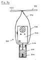
- FIG. 2 shows an example of an ultrasound Doppler device 400a which is packaged in the device according to FIG. 1 in a non-sterile state. It consists of an electronics housing 400, an electrical cable 500 and an ultrasound probe 600. On the housing 400 there are an on / off switch 430, a loudspeaker 410, a rotary knob 440 for volume control, and an optical display 420, 421 for Display of blood flow direction. If the emitted ultrasonic waves and the flowing blood move largely in the same direction, for example the optical display 420 lights up, and if both directions are largely opposite, the optical display 421 lights up. The combination of the acoustic and optical signals makes sense because it can facilitate the distinction between veins and arteries.
- the ultrasound probe has a groove 610 in a manner known per se, which is arranged such that the axis of one in the innermost part 620 of the groove adjacent guide tube (not shown in Figure 2) for a puncturing needle to the center of the emitted ultrasound field and parallel to it this field is aligned.
- FIG. 3a and 3b show two phases of the introduction of the non-sterile ultrasound Doppler device 400a (FIG. 2) into the inventive device 100a according to FIG. 1.
- a sterile hand 800 is inserted between the everted part 115 and the unturned part 110 of the tubular packaging spine 100 (FIG. 3a), so that this hand 800 is protected from contamination by the non-sterile device 400a.
- the non-sterile person inserts the non-sterile device into the opening 128 of the tube 100 with his hand 810. With her second hand (not shown), the sterile person then pulls up the turned part 115 of the tube 100 (FIG. 3b) and with the help of the straps 125, she closes the tube 100 at the top.
- the non-sterile device 400a is packaged in the device 100a and is therefore suitable for the sterile area.
- the hose 100 can of course also be closed by other means, such as, for example, mini-grips, clamping devices or adhesives.
- the ultrasound probe 600 is then passed through the sterile person Advance hose 100 into cap 300.
- the probe 600 becomes the probe guide part 310 of the cap, as far as pushed into the cap 300, until the guide tube 340 passes through the innermost part 620 of the groove 610 and is in the groove.
- the guide tube 340 can be fastened to a web 335. Since the innermost part 620 of the groove 610 is aligned with the direction of the emitted field, a puncturing needle (not shown) inserted through the guide tube 340 will also approximately coincide with the ultrasound axis and thereby puncture a located vessel.
- the ultrasound probe is very can be brought close to the patient's skin on a lead track can be dispensed with (see also description in connection with the Figure 7). However, if a lead section is provided, this will make it easier the mechanical coupling between the ultrasound probe and the patient's skin.
- Figures 5 and 6 show variants of the Cap with lead section in average.
- the lead section 700 consists, for example, of a dimensionally stable, water-containing gel which has low ultrasound damping and, thanks to its deformability, allows good coupling to the ultrasound probe.
- the probe-side surface 710 of the lead section 700 is slightly convex and is displaced somewhat when the ultrasound probe 600 is inserted, so that no air remains between the end face 630 of the ultrasound probe 600 and the probe-side surface 710 of the lead section 700.
- a fixed plate 331 ( FIG. 6 ), which can be part of the cap 300.
- the plate 331 completely separates the ultrasound probe from the lead section 700, so that the latter is not displaced by the ultrasound probe.
- the plate 331 can be made of plastic, which has only a low ultrasound absorption at a thickness of 0.5 to 2 mm.
- at least one of the two surfaces should be wetted with gel or saline solution before the probe is inserted into the cap.
- the inner surface 331a of the plate 330 can be wetted during the production of the cap 300, in that a thin layer 710a made of a similar material to that of the lead section 700 covers the surface 331a.
- the plate 331 can also consist of a plastic, e.g. made of plexiglass, which has a greater sound propagation speed than the water-containing one Gel of the lead section 700. If the surface 331b is then concave, see above the plate 331 has a focusing effect on the ultrasonic field.
- the Disposable cap 300 thus also has the function of a replaceable one Ultrasound lens, the focal distance to the depth of the vessels to be located can be optimized.
- the plate is made of a material with a smaller one Speed of sound propagation as the material of the lead section, the surface 331b of the plate 331 is provided convex.
- a solid plastic can also be used as the material for the lead section, such as. Urethane gum. Such plastics have a larger one Ultrasound absorption on than the water-containing gels, but they are not slippery, so that no special precautions are necessary for their attachment are.
- the lead section can be in a lead section 320 of the cap 300 may be arranged. Lead distance and corresponding Cap wall can also be used as a separate part of the cap be put on. If the lead track material is solid, the lead track can be provided with or without a corresponding wall.
- FIG. 7 shows an exemplary embodiment of the device according to the invention without a leading section 700.
- the cap (only probe guide part) is reduced to the guide tube 340, which, together with an optional web 335, connects two plates 333 and 360.
- a gel layer is applied between the patient skin (not shown) and the front surface 333b of the front plate 333 for coupling, as is customary with conventional ultrasound probes.
- the cap-side end of the packaging piece 110 is closed.
- the reduced cap 300a then lies within the packaging piece, which is, for example, welded or glued to the front plate 333 and to the rear plate 360.
- the puncturing needle (not shown) can easily pierce the thin wall of the package.
- the guide tube plate 333 may be wedge-shaped. It then advantageously exists made of a plastic suitable as a lead section (e.g. urethane rubber) or in the manner of the lead section already described the cap from a substantially tubular wall (for example made of plastic), which surrounds a gel as a lead.
- a plastic suitable as a lead section e.g. urethane rubber
- a substantially tubular wall for example made of plastic
- a tubular packaging piece 100 can be attached to the cap 300 with the aid of a frame 200 ( FIG. 8 ) which is glued, welded or pressed onto one end of the packaging piece and over which the cap 300 is pushed.
- a frame 200 FIG. 8
- This embodiment is advantageous if the cap 300 is only connected to the packaging piece 100 and shortly before use because the cap 300 has a lead section 700 made of a water-containing gel and is therefore kept in its own, water-vapor-tight packaging.
- the cap 300 can also be attached to the packaging piece 100 during manufacture, which is particularly advantageous if the lead section 700 is made of plastic or if it is missing, so that no water-vapor-tight packaging is necessary.
- the optical direction indicator is in the field of vision of the doctor during the puncture, as shown in FIG. 9 , this indicator 680 and 681 should be on the handle 600a of the ultrasound probe.
Landscapes
- Health & Medical Sciences (AREA)
- Life Sciences & Earth Sciences (AREA)
- Physics & Mathematics (AREA)
- Surgery (AREA)
- Medical Informatics (AREA)
- Animal Behavior & Ethology (AREA)
- Radiology & Medical Imaging (AREA)
- Engineering & Computer Science (AREA)
- Biomedical Technology (AREA)
- Heart & Thoracic Surgery (AREA)
- Nuclear Medicine, Radiotherapy & Molecular Imaging (AREA)
- Molecular Biology (AREA)
- Biophysics (AREA)
- Pathology (AREA)
- General Health & Medical Sciences (AREA)
- Public Health (AREA)
- Veterinary Medicine (AREA)
- Optics & Photonics (AREA)
- Acoustics & Sound (AREA)
- Ultra Sonic Daignosis Equipment (AREA)
- Medical Preparation Storing Or Oral Administration Devices (AREA)
- External Artificial Organs (AREA)
- Measuring Pulse, Heart Rate, Blood Pressure Or Blood Flow (AREA)
Abstract
Description
Der Gegenstand der Erfindung betrifft eine Vorrichtung gemäß Anspruch 1, die mit einem Ultraschall-Doppler-Gerät und einer Punktiernadel in einem sterilen Bereich eine nicht invasive Ortung und eine Punktion von von Blutgefässen erlaubt. Das Ultraschall-Doppler-Gerät ist dabei nicht steril und für wiederholte Anwendungen vorgesehen und wird vor jedem Gebrauch mit Hilfe der sterilen Verpackung steril verpackt.The object of the invention relates to a Apparatus according to claim 1, which with an ultrasonic Doppler device and Puncturing needle in one sterile area a non-invasive location and puncture of blood vessels allowed. The ultrasound Doppler device is not sterile and for repeated use Applications are provided and is helped before each use sterile packaging.
Es ist bekannt, dass Ultraschallgeräte beim Punktieren von zentralen Venen und von Arterien nützlich sein können. Dies gilt insbesondere für bildgebende Ultrasehallgeräte, auf deren Bildschirme nicht nur ein Schnittbild der untersuchten Körpergegend, sondern auch die Punktiernadel zu sehen ist, was die Punktion erheblich erleichtern kann. Eine solche Methode ist bspw. in New England Journal of Medicine 324:566, February 1991 beschrieben. Ultraschallsonden lassen sich aber nur schwer sterilisieren, weshalb sie vor ihrem Gebrauch in einen sterilen, schlauchartigen Überzug eingepackt werden, wie z.B. in der EP-0'477'581 A1 beschrieben ist. Seitlich an der Ultraschallsonde und über den sterilen Überzug kann ein steriles Koppelstück befestigt werden, welches die Punktiernadel in die Ultraschall-Schnittebene führt, so dass die Punktiernadel auf dem Bildschirm sichtbar ist (wie bspw. in US-4'898'178 beschrieben ist). Solche bildgebende Geräte sind aber nicht sterilisierbar und so gross, dass sie kaum steril eingepackt werden können und deshalb eine eigene Abstellfläche ausserhalb des sterilen Operationsfeldes brauchen. Ein mindestens zwei Meter langes, elektrisches Kabel verbindet dann die Ultraschallsonde mit dem elektronischen Gehäuse, was in den engen räumlichen Verhältnissen von Intensivstationen oder Katheterisationssälen nachteilig ist.It is known to use ultrasound machines when puncturing central veins and can be useful from arteries. This is especially true for imaging Ultrasound devices, on the screens of which not only a sectional image of the examined Body area, but also the puncture needle is what the Puncture can significantly facilitate. Such a method is, for example, in New England Journal of Medicine 324: 566, February 1991. Ultrasound probes but are difficult to sterilize, which is why they are used before be wrapped in a sterile, tubular cover, e.g. is described in EP-0'477'581 A1. On the side of the ultrasound probe and A sterile coupling piece can be attached over the sterile cover, which leads the puncturing needle into the ultrasound cutting plane so that the Puncturing needle is visible on the screen (such as in US-4,898,178 is described). However, such imaging devices cannot be sterilized and so big that they can hardly be packed sterile and therefore one need their own storage space outside the sterile operating field. A The ultrasonic probe then connects at least two meters of electrical cable with the electronic housing, what in the narrow spatial Ratios of intensive care units or catheterization rooms is disadvantageous.
Ebenfalls bekannt sind Ultraschall-Doppler-Geräte, welche nur akustische Signale wiedergeben und deshalb wesentlich kleiner und billiger sein können als die bildgebenden. Bei den meisten dieser Doppler-Geräte ist aber die Punktiernadel mit der Achse des Ultraschallfeldes nahezu identisch. Als Folge liegen die Piezzokristalle der Ultraschallsonde und die Punktiernadel räumlich so eng aneinander, dass eine Kontaminierung der Ultraschallsonde durch das Patientenblut erfolgt. Dies gilt insbesondere für Vorrichtungen, bei welchen die Piezzokristalle sich innerhalb der Nadel oder der Spritze befinden, wie es z.B. in den US-3'556'079, EP-0'260'953 oder US-5'131'394 beschrieben ist. Eine Kontaminierung findet aber auch dann statt, wenn die Ultraschallsonde um die Nadel herum angeordnet ist, wie z.B. in CH-501'410 beschrieben. Die kontaminierten Ultraschallsonden können gassterilisiert werden, aber dieser Vorgang ist zeitraubend und verkürzt zudem die Lebensdauer der teuren Ultraschallsonden erheblich. Teuer ist es auch, die Ultraschallsonde nach einmaligem Gebrauch wegzuwerfen, wie manche Hersteller es empfehlen.Also known are ultrasonic Doppler devices, which are only acoustic Play signals and can therefore be much smaller and cheaper than the imaging. With most of these Doppler devices, however, that is Puncturing needle almost identical to the axis of the ultrasound field. As a result the piezo crystals of the ultrasound probe and the puncture needle are spatially located so close together that contamination of the ultrasound probe by the Patient blood is made. This applies in particular to devices in which the piezocrystals are inside the needle or syringe as is e.g. in US-3,556,079, EP-0,260,953 or US-5,131,394. Contamination also occurs when the ultrasound probe is used is arranged around the needle, e.g. in CH-501'410. The Contaminated ultrasound probes can be gas sterilized, but this one The process is time-consuming and also shortens the lifespan of the expensive ones Ultrasound probes significantly. It is also expensive to replace the ultrasound probe once Throw away use, as some manufacturers recommend.
In der EP-0'516'582 A1 wird nun eine Vorrichtung beschrieben, bei welcher eine nicht sterile Ultraschallsonde benützt werden kann, weil sie weder die Punktiernadel, noch die Handschuhe des Arztes, noch die Patientenhaut kontaminieren kann. Auf die nicht sterile Ultraschallsonde wird nämlich ein steriles Koppelstück aufgesteckt, in welchem mit Hilfe eines Spiegels das Ultraschallfeld derart umgelenkt wird, dass die Punktiernadel, die ebenfalls durch das Koppelstück geführt wird, parallel zum Ultraschallfeld und in dessen Zentrum auf die Patientenhaut gerichtet ist Der Abstand zwischen der Punktiernadel und der Ultraschallsonde beträgt dabei mindestens den halben Durchmesser der Ultraschallsonde, so dass diese die Punktiernadel nicht kontaminieren kann. Das Koppelstück muss aber hohe Anforderungen bezüglich der Herstellgenauigkeit erfüllen, weil es die Ultraschallsonde, den Spiegel und die Nadelführung relativ zueinander sehr genau positionieren muss. Zudem muss das Koppelstück luftfrei mit ultraschall-leitendem Gel gefüllt und mit durchstechbaren Elastomer-Membranen abgeschlossen sein, damit das Gel nicht herausfliesst. Diese Merkmale machen das Koppelstück, das als Einwegartikel vorgesehen ist, relativ teuer.EP-0'516'582 A1 describes a device in which a non-sterile ultrasound probe can be used because it does not have the Puncture the needle, the doctor's gloves and the patient's skin can. This is because a sterile is placed on the non-sterile ultrasound probe Coupling piece plugged in, with the help of a mirror, the ultrasonic field is deflected such that the puncturing needle, which is also through the coupling piece is guided, parallel to and in the ultrasonic field The center of the patient's skin is the distance between the puncture needle and the ultrasound probe is at least half Diameter of the ultrasound probe so that the puncture needle is not can contaminate. The coupling piece has to meet high requirements the manufacturing accuracy because it is the ultrasonic probe Position the mirror and the needle guide very precisely relative to each other got to. In addition, the coupling piece must be air-free with ultrasound-conducting gel filled and sealed with pierceable elastomer membranes, so that the gel doesn't flow out. These features make the coupling piece which is intended as a disposable item, relatively expensive.
Die meisten bekannten Verfahren zur sterilen Verpackung von nicht sterilen Ultrasthallgeräten oder Sonden bedingen eine Zusammenarbeit einer nicht sterilen mit einer sterilen Person, wie dies beispielsweise in den bereits genannten Schriften EP-0'477'581 A1 und EP-0'516'582 A1 beschrieben ist. Im Dokument EP-A-0540461 ist insbesondere eine Ultraschallsonde mit Nut offenbart, die in eine sterile Kappe mit Führungsrohr einbringbar ist. Das elektrische Kabel zur Verbindung der Sonde mit dem Ultraschallgerät ist dabei allerdings an der sterilen Kappe selber vorgesehen (die Kontaktstellen für die Sonde enthält). Somit ergibt sich aus diesem Gerät keine Notwendigkeit, ein weiteres schlauchförmiges, flexibles Verpackungsstück vorzusehen, durch dessen proximale Öffnung die Sonde und ein Teil des damit verbundenen Kabels einbringbar ist. Gemäss EP-0'540'461 A1 kann eine nicht sterile Person die Verpackung allein übernehmen und die Sonde auf gewohnte Art an die sterile Person übergeben In diesem Falle gehören aber das elektrische Kabel und die beiden elektrischen Stecker, welche die Ultraschallsonde mit der Elektronik verbinden, zum Einwegteil, was diesen teuer macht.Most known methods for the sterile packaging of non-sterile Ultrasound devices or probes do not require cooperation sterile with a sterile person, such as those already mentioned Writings EP-0'477'581 A1 and EP-0'516'582 A1 are described. Document EP-A-0540461 in particular discloses an ultrasonic probe with a groove, which can be placed in a sterile cap with a guide tube. The electrical cable for However, the connection of the probe with the ultrasound device is on the sterile one Cap provided (which contains contact points for the probe). Hence it follows out of this device no need another flexible, tubular Provide packaging, through the proximal opening of the probe and a Part of the associated cable can be inserted. According to EP-0'540'461 A1, a non-sterile person can do the packaging alone take over and hand over the probe to the sterile person in the usual way In this case, however, the electrical cable and the two electrical belong Connectors that connect the ultrasound probe to the electronics, to the disposable part, which makes it expensive.
Das Ziel der vorliegenden Erfindung ist nun die Schaffung einer Vorrichtung, mit der in einem sterilen Bereich Blutgefässe nicht-invasiv geortet und punktiert werden können. Bei der erfindungsgemäßen Vorrichtung nach Anspruch 1 kommt insbesondere ein Ultraschall-Doppler-Gerät mit einer entsprechenden Sonde und mit einer Punktiemadel zur Anwendung, wobei das Ultraschall-Doppler-Gerät, insbesondere auch die Sonde, nicht steril zu sein brauchen. Die Verpackung der erfindungsgemäßen Vorrichtung soll als Einwegartikel nicht teuer sein. Die Verpackung soll in üblicher Weise von einer unsterilen Person zusammen mit einer sterilen Person mit den unsterilen Teilen (Ultraschallgerät mit Sonde) unmittelbar vor der Verwendung zusammengebracht werden können. Dabei soll mit Hilfe der Verpackung sowohl die Punktiernadel parallel zum Ultraschallfeld und in dessen Zentrum auf die Patientenhaut richtbar sein als auch soll die Sonde derart nahe an der Patientenhaut positionierbar sein, dass eine Ortung auch ohne Vorlaufstrecke möglich wird. Die Handhabung der Vorrichtung soll dabei mindestens so einfach und problemlos sein wie bei bekannten derartigen Verpackungen. Dieses Ziel wird durch die in den Patentansprüchen definierte Erfindung erreicht.The aim of the present invention is now to provide a device with which blood vessels are located and punctured non-invasively in a sterile area can be. In the device according to the invention according to claim 1 comes in particular Ultrasound Doppler device with an appropriate probe and with a puncture needle for use, the ultrasonic Doppler device, in particular also the probe does not need to be sterile. The packaging of the The device according to the invention is intended as a disposable item not be expensive. The packaging should be in the usual way by a non-sterile person together with a sterile person with the non-sterile parts (ultrasonic device with Probe) can be brought together immediately before use. With the help of the packaging, both the puncture needle should be parallel to the Ultrasound field and in the center of the patient's skin can be directed as it should also be possible to position the probe so close to the patient's skin that localization is also possible without a lead. The handling of the Device should be at least as simple and easy as in known such packaging. This goal is achieved by the in the claims defined invention achieved.
Das steril verpackte Punktiergerät setzt sich im wesentlichen zusammen aus einem nicht sterilen Ultraschall-Doppler-Gerät, welches akustische und/oder optische Signale senden kann, aus einer erfindungsgemässen sterilen Verpackung und aus einer sterilen Punktiernadel, wobei die Verpackung für den Kontakt mit der Patientenhaut eine Kappe und ein an die Kappe anschliessendes, vorzugsweise flexibles Verpakkungsstück aufweist. Das flexible Verpackungsstück besteht beispielsweise aus einem Stück eines flexiblen Schlauches, das an einem Ende mit der Kappe verschlossen ist und am anderen Ende verschliessbar ist Kurz vor der Benutzung des Punktiergerätes wird das nicht sterile Dopplergerät in diese sterile Verpackung so eingeführt und die Verpackung verschlossen, dass die Aus-senfläche der Verpackung steril bleibt und entsprechend im sterilen Bereich des Operationssaales benützt werden kann. Die Kappe ist derart ausgestaltet, dass durch sie die Sonde des Ultraschall-Doppler-Gerätes in einer definierten Position relativ zu einem in der Kappe integrierten Führungsrohr für die Punktiernadel gehalten wird, derart, dass die Achse des Führungsrohres mit derjenigen des Feldes der Ultraschallsonde im wesentlichen zusammenfällt. Die sterile Verpackung ist beim Gebrauch verschlossen und das Führungsrohr ist durchgehend durch die Kappe angeordnet, sodass die unsterile Ultraschallsonde weder die Punktiernadel, noch den Patienten, noch die Handschuhe des Arztes kontaminieren kann. Nach Gebrauch wird die kostengünstige, sterile Verpackung (Kappe und flexibles Verpackunggsstück) weggeworfen. Weder das Gerät noch die Sonde müssen vor dem nächsten Gebrauch sterilisiert werden.The sterile-packed puncture device essentially settles together from a non-sterile ultrasound Doppler device, which can send acoustic and / or optical signals from an inventive sterile packaging and from a sterile puncture needle, the packaging for contact with the patient's skin is a Cap and a preferably flexible packaging piece adjoining the cap having. The flexible packaging piece consists of, for example a piece of flexible tubing that is capped at one end is locked and can be locked at the other end Shortly before use of the puncturing device, the non-sterile Doppler device is converted into this sterile one The packaging is inserted and the packaging is closed so that the outer surface the packaging remains sterile and accordingly in the sterile area of the operating room can be used. The cap is designed that through it the probe of the ultrasound Doppler device in a defined Position relative to a guide tube for the integrated in the cap Puncturing needle is held such that the axis of the guide tube with that of the field of the ultrasound probe essentially coincides. The sterile packaging is closed during use and the guide tube is arranged continuously through the cap so that the non-sterile ultrasound probe neither the puncture needle, nor the patient, nor the gloves of the Doctor can contaminate. After use, the inexpensive, sterile Packaging (cap and flexible packaging) thrown away. Neither that The device or the probe must be sterilized before the next use.
Das Ultraschall-Doppler-Gerät kann batteriebetrieben sein und ein Taschenformat aufweisen, so dass es keine spezielle Abstellfläche benötigt. Dadurch kann das elektrische Kabel, das die Ultraschallsonde mit dem Rest der Elektronik verbindet, entsprechend kurz sein, was eine leichte Einführung des ganzen unsterilen Gerätes in die sterile Verpackung erlaubt.The ultrasound Doppler device can be battery operated and a pocket size have so that it does not require a special storage space. Thereby can the electrical cable that connects the ultrasound probe to the rest of the electronics connects, be accordingly short, which is an easy introduction to the whole non-sterile device allowed in the sterile packaging.
Das Ultraschall-Dopplergerät kann aber auch grösser sein, wobei ElektronikGehäuse und Sonde mit einem längeren elektrischen Kabel verbunden sind, derart, dass das Elektronik-Gehäuse ausserhalb des sterilen Feldes gestellt werden kann und folglich nicht steril eingepackt werden muss. Damit die optische Richtungsanzeige sich aber beim Punktieren im Blickfeld des Arztes befindet, ist es dann vorteilhaft, die Richtungsanzeige auf dem Sondengehäuse unterzubringen und nicht auf dem Elektronik-Gehäuse.However, the ultrasound Doppler device can also be larger, with the electronics housing and probe are connected to a longer electrical cable such that the electronics housing is placed outside the sterile field can be and therefore does not have to be packed sterile. So that optical directional display but when puncturing in the field of vision of the doctor it is then advantageous to display the direction on the probe housing to accommodate and not on the electronics housing.
Die Kappe kann eine Vorlaufstrecke enthalten, welche die mechanische Ankoppelung zwischen der Ultraschallsonde und der Haut des Patienten erleichtert. The cap can contain a lead section, which is the mechanical coupling between the ultrasound probe and the patient's skin.
Die als Einwegartikel vorgesehene, erfindungsgemässe Verpackung besteht vorzugsweise aus Kunststoff, wobei einzelne Komponenten wie die Nadelführung auch metallisch sein können. Die Vorlaufstrecke kann aus ultraschallleitendem Kunststoff oder aus wasserhaltigem Gel bestehenThe packaging according to the invention, which is provided as a disposable article, exists preferably made of plastic, with individual components such as the needle guide can also be metallic. The lead section can be made of ultrasound Plastic or water-containing gel
Anhand der nachfolgenden Figuren werden einige Ausführungsbeispiele der erfindungsgemässen Vorrichtung im Detail diskutiert Es zeigen:
- Fig. 1
- die sterilen Einwegteile einer beispielhaften Ausführungsform der erfindungsgemässen Vorrichtung;
- Fig.2
- ein Ultraschall-Doppler-Gerät, das in der Vorrichtung gemäss Figur 1 steril verpackt werden kann;
- Fig. 3a-b
- zwei Phasen beim sterilen Verpacken des nicht sterilen Dopplergerätes nach Fig. 2 mittels der Vorrichtung der Fig. 1;
- Fig. 4
- eine perspektivische Ansicht einer Kappe für die erfindungemässe Vorrichtung;
- Fig. 5 und 6
- zwei Ausführungsformen von Kappen mit Vorlaufstrecken im Schnitt;
- Fig. 7
- eine weitere Ausführungsform der erfindungsgemässen Vorrichtung;
- Fig. 8
- eine beispielhafte Verbindung zwischen Kappe und flexiblem Verpackungsstück;
- Fig. 9
- eine weitere Ultraschallsonde;
- Fig. 1
- the sterile disposable parts of an exemplary embodiment of the device according to the invention;
- Fig. 2
- an ultrasound Doppler device that can be sterile packed in the device according to FIG. 1;
- 3a-b
- two phases in the sterile packaging of the non-sterile Doppler device according to FIG. 2 by means of the device of FIG. 1;
- Fig. 4
- a perspective view of a cap for the device according to the invention;
- 5 and 6
- two embodiments of caps with lead sections on average;
- Fig. 7
- a further embodiment of the device according to the invention;
- Fig. 8
- an exemplary connection between the cap and flexible packaging piece;
- Fig. 9
- another ultrasound probe;
Fig. 1 zeigt eine beispielhafte Ausführungsform (100a) der Verpackung für
die erfindungsgemässe Vorrichtung. Diese besteht im wesentlichen aus einem flexiblen Schlauch
100 (flexibles Verpackungsstück), einer Kappe 300 und einem Rahmen 200
(Verbindung zwischen Kappe und flexiblem Verpackungsstück). Vor der Einführung
des Ultraschall-Doppler-Gerätes durch die Öffnung 128 des
Schlauches 100 ist dessen oberes Ende 115 zurückgestülpt. Am unteren Ende
des Schlauches 100 ist der Rahmen 200 befestigt, welcher eine mechanische
Verbindung zwischen dem flexiblen Schlauch 100 und der mindestens teilweise
starren Kappe 300 ermöglicht. Wenn die Kappe 300 auf den Rahmen 200
gesteckt ist, bilden sie zusammen mit dem Schlauch 100 einen Hohlraum, der
nur eine, beispielsweise mit Bändern 125 verschliessbare Öffnung 128 aufweist.
Die Kappe 300 weist einen Sondenführungsteil 310 und einen Vorlaufstreckenteil
320 mit einer Vorlaufstrecke 700 auf. Ein Führungsrohr 340 fuhr
eine Punktiernadel 380 durchdringt beide Kappenteile 310 und 320. 1 shows an exemplary embodiment (100a) of the packaging for the device according to the invention. This essentially consists of a flexible tube 100 (flexible packaging piece), a
Fig. 2 zeigt ein Beispiel eines Ultraschall-Dopplergeräts 400a, das in nichtsterilem
Zustand in die Vorrichtung gemäss Figur 1 verpackt wird. Es
besteht aus einem Elektronik-Gehäuse 400, einem elektrischen Kabel 500 und
einer Ultraschallsonde 600. Auf dem Gehäuse 400 befinden sich ein Ein/Aus
Schalter 430, ein Lautsprecher 410, ein Drehknopf 440 für die Lautstärkeregulierung,
sowie eine optische Anzeige 420, 421 zur Anzeige der Blutstömungsrichtung.
Falls die emittierten Ultraschallwellen und das strömende Blut sich
weitgehend in die gleiche Richtung bewegen, leuchtet z.B. die optische Anzeige
420, und falls beide Richtungen weitgehend entgegengesetzt sind, so leuchtet
die optische Anzeige 421. Die Kombination der akustischen und optischen
Signale ist sinnvoll, weil sie die Unterscheidung zwischen Venen und Arterien
erleichtern kann. FIG. 2 shows an example of an
Die Ultraschallsonde weist in an sich bekannter Weise eine Nut 610 auf, die
derart angeordnet ist, dass die Achse eines im innersten Teil 620 der Nut
anliegenden Führungsrohres(in der Figur 2 nicht dargestellt) für eine Punktiernadel
auf das Zentrum des ausgestrahlten Ultraschallfeldes und parallel zu
diesem Feld ausgerichtet ist. The ultrasound probe has a
In den Fig. 3a und 3b sind zwei Phasen des Einführens des unsterilen Ultraschall-Doppler-Gerätes
400a (Fig. 2) in die erfindungsgemässe Vorrichtung
100a gemäss Fig. 1 dargestellt. Eine sterile Hand 800 wird zwischen den
gestülpten Teil 115 und den ungestülpten Teil 110 des schlauchförmigen Verpackungssrückes
100 eingeführt (Fig. 3a), so dass diese Hand 800 von einer
Kontamination durch das unsterile Gerät 400a geschützt ist. Die nicht sterile
Person führt mit ihrer Hand 810 das nicht sterile Gerät in die Öffnung 128
des Schlauches 100 ein. Mit ihrer zweiten Hand (nicht dargestellt) zieht dann
die sterile Person den gestülpten Teil 115 des Schlauches 100 hoch (Fig. 3b)
und mit Hilfe der Bänder 125 schliesst sie den Schlauch 100 oben zu. Somit
ist das unsterile Gerät 400a in der Vorrichtung 100a verpackt und dadurch für
den sterilen Bereich tauglich. Der Schlauch 100 kann selbstverständlich auch
mit anderen Mitteln geschlossen werden wie z.B. Minigrips, Klemmvorrichtungen
oder Klebstoffen. 3a and 3b show two phases of the introduction of the non-sterile
Die Ultraschallsonde 600 wird dann durch die sterile Person durch den
Schlauch 100 in die Kappe 300 vorgeschoben. Die Sonde 600 wird, vom Sondenführungsteil
310 der Kappe geführt, soweit in die Kappe 300 vorgeschoben,
bis das Führungsrohr 340 durch den innersten Teil 620 der Nut 610 verläuft
und in der Nut ansteht.The
Das Führungsrohr 340 kann, wie auch aus der Figur 4 ersichtlich ist, an einem
Steg 335 befestigt sein. Da der innerste Teil 620 der Nut 610 auf die Richtung
des emittierten Feldes ausgerichtet ist, wird eine durch das Führungsrohr 340
eingeführte Punktiernadel (nicht dargestellt) ebenfalls annäherend mit der
Ultraschall-Achse zusammenfallen und ein geortetes Gefäss dadurch auch
punktieren. As can also be seen from FIG. 4, the
Da mit Hilfe der erfindungsgemässen Vorrichtung die Ultraschallsonde sehr nahe an die Patientenhaut gebracht werden kann, kann auf eine Vorlaufstrecke verzichtet werden (siehe auch Beschreibung im Zusammenhang mit der Figur 7). Ist aber trotzdem eine Vorlaufstrecke vorgesehen, erleichtert diese die mechanische Ankoppelung zwischen der Ultraschallsonde und der Patientenhaut. Figuren 5 und 6 zeigen Ausführungsvarianten der Kappe mit Vorlaufstrecke jeweils im Schnitt.Since with the help of the device according to the invention, the ultrasound probe is very can be brought close to the patient's skin on a lead track can be dispensed with (see also description in connection with the Figure 7). However, if a lead section is provided, this will make it easier the mechanical coupling between the ultrasound probe and the patient's skin. Figures 5 and 6 show variants of the Cap with lead section in average.
In der Ausführungsvariante gemäss Figur 5 besteht die Vorlaufstrecke 700
beispielsweise aus einem formbeständigen, wasserhaltigen Gel, das eine geringe
Ultraschalldämpfung aufweist und dank seiner Verformbarkeit eine gute
Ankoppelung an die Ultraschallsonde erlaubt. Die sondenseitige Fläche 710
der Vorlaufstrecke 700 ist leicht konvex und wird beim Einschieben der Ultraschallsonde
600 etwas verdrängt, so dass keine Luft zwischen der Stirnfläche
630 der Ultraschallsonde 600 und der sondenseitigen Fläche 710 der
Vorlaufstrecke 700 bleibt. In the embodiment variant according to FIG. 5 , the
Sondenseitig ist es aber auch möglich eine feste Platte
331 vorzusehen (Fig. 6), welche ein Bestandteil der Kappe 300 sein kann. Die
Platte 331 trennt die Ultraschallsonde von der Vorlaufstrecke 700 vollständig,
so dass letztere durch die Ultraschallsonde nicht verdrängt wird. Die Platte
331 kann aus Kunststoff bestehen, welcher bei einer Dicke von 0,5 bis 2 mm
nur eine niedrige Ultraschallabsorbtion aufweist. Um eine gute Ankoppelung
zwischen der vorlaufseitigen Stirnfläche der Ultraschallsonde und der Innenfläche
331a der Platte 331 zu gewährleisten sollte mindestens eine der beiden
Flächen mit Gel oder Kochsalzlösung vor dem Einfuhren der Sonde in die
Kappe benetzt werden. Die Benetzung der Innenfläche 331a der Platte 330
kann während der Herstellung der Kappe 300 erfolgen, indem eine dünne
Schicht 710a aus einem ähnlichen Material wie dasjenige der Vorlaufstrecke
700 die Fläche 331a bedeckt.On the probe side, however, it is also possible to provide a fixed plate 331 ( FIG. 6 ), which can be part of the
Die Platte 331 kann auch aus einem Kunststoff bestehen, z.B. aus Plexiglas,
der eine grössere Schallausbreitungs-Geschwnidigkeit aufweist, als das wasserhaltige
Gel der Vorlaufstrecke 700. Ist dann die Fläche 331b konkav, so
hat die Platte 331 eine fokussierende Wirkung auf das Ultraschallfeld. Die
Einwegkappe 300 weist somit zusätzlich die Funktion einer auswechselbaren
Ultraschall-Linse auf, deren Fokaldistanz auf die Tiefe der zu ortenden Gefässe
optimierbar ist. Besteht die Platte aus einem Material mit einer kleineren
Schallausbreitungsgeschwindigkeit als das Material der Vorlaufstrecke,
wird die Fläche 331b der Platte 331 konvex vorgesehen.The plate 331 can also consist of a plastic, e.g. made of plexiglass,
which has a greater sound propagation speed than the water-containing one
Gel of the
Als Material für die Vorlaufstrecke kommt auch ein fester Kunststoff in Frage,
wie z.B. Urethangummi. Solche Kunststoffe weisen zwar eine grössere
Ultraschallabsorbtion auf als die wasserhaltigen Gele, dafür sind sie nicht glitschig,
so dass für ihre Befestigung keine speziellen Vorkehrungen notwendig
sind. Die vorlaufstrecke kann, wie in den Figuren dargestellt in einem Vorlaufstreckenteil
320 der Kappe 300 angeordnet sein. Vorlaufstrecke und entsprechende
Kappenwandung können auch als separater Teil auf die Kappe
aufgesetzt werden. Ist das Vorlaufstreckenmaterial fest, kann die Vorlaufstrecke
mit oder ohne entsprechende Wandung vorgesehen sein. A solid plastic can also be used as the material for the lead section,
such as. Urethane gum. Such plastics have a larger one
Ultrasound absorption on than the water-containing gels, but they are not slippery,
so that no special precautions are necessary for their attachment
are. As shown in the figures, the lead section can be in a
Figur 7 zeigt eine beispielhafte Ausführungsform der erfindungsgemässen
Vorrichtung ohne Vorlaufstrecke 700. Die Kappe (nur Sondenführungsteil) ist
in dieser Ausführungsform reduziert auf das Führungsrohr 340, das zusammen
mit einem fakultativen Steg 335 zwei Platten 333 und 360 verbindet. Bei der
Anwendung dieser Ausführungsform wird zur Ankoppelung, wie es mit konventionellen
Ultraschallsonden üblich ist, eine Gelschicht zwischen der Patientenhaut
(nicht dargestellt) und der Vorderflache 333b der vorderen Platte 333
aufgebracht. In dieser Ausführungsform ist das kappenseitige Ende des Verpackungsstückes
110 geschlossen Die reduzierte Kappe 300a liegt dann innerhalb
des Verpackungsstuckes, welches mit der vorderen Platte 333 und mit
der hinteren Platte 360 beispielsweise verschweisst oder verklebt ist. Die
Punktiernadel (nicht dargestellt) kann die dünne Wandung des Verpackungsstückes
leicht durchstechen. FIG. 7 shows an exemplary embodiment of the device according to the invention without a leading
Für eine Hautkontaktfläche mit einem Winkel von 30° bis 45° zum Führungsrohr
kann die Platte 333 keilförmig ausgestaltet sein. Sie besteht dann vorteilhafterweise
aus einem als Vorlaufstrecke geeigneten Kunststoff (z. B. Urethangummi)
oder in der Art des bereits beschriebenen Vorlaufstreckenteils
der Kappe aus einer im wesentlichen rohrförmigen Wandung (beispielsweise
aus Kunststoff), die ein Gel als Vorlaufstrecke umgibt. For a skin contact surface with an angle of 30 ° to 45 ° to the
Die Befestigung eines schlauchförmigen Verpackungsstuckes 100 an der Kappe
300 kann mit Hilfe eines Rahmens 200 erfolgen (Fig. 8), welcher am
einen Ende des Verpackungsstückes angeklebt, angeschweisst oder angepresst
ist, und über welchen die Kappe 300 geschoben wird. Diese Ausführungsform
ist dann vorteilhaft, wenn die Kappe 300 erst und Spital und kurz vor dem
Gebrauch mit dem Verpackungsstück 100 verbunden wird, weil die Kappe 300
eine Vorlaufstrecke 700 aus einem wassehaltigen Gel aufweist und deshalb in
einer eigenen, wasserdampfdichten Verpackung aufbewahrt wird. Die Kappe
300 kann aber auch bereits bei der Fabrikation am Verpackungsstück 100
befestigt werden, was besonders vorteilhaft ist, wenn die Vorlaufstrecke 700
aus Kunststoff besteht, oder wenn sie fehlt, so dass keine wasserdampfdichte
Verpackung nötig ist.A
Befindet sich das Elektronik-Gehäuse ausserhalb des sterilen Feldes, muss nur
ein Teil des Kabels und die Sonde steril verpackt werden. Damit sich aber
auch in diesem Falle die optische Richtungsanzeige während der Punktion im
Blickfeld des Arztes befindet, soll sich, wie in Figur 9 dargestellt, diese Anzeige
680 und 681 auf dem Griff 600a der Ultraschallsonde befinden.If the electronics housing is outside the sterile field, only part of the cable and the probe need to be sterile packed. However, so that the optical direction indicator is in the field of vision of the doctor during the puncture, as shown in FIG. 9 , this
Claims (7)
- Combination of a non-sterile ultrasonic Doppler apparatus (400a) for locating and puncturing blood vessels, which ultrasonic Doppler apparatus (400a) has a non-sterile probe (600) with a groove (610) running in the direction of the emitted ultrasonic field, a non-sterile electronic unit (400) and a non-sterile cable (500) connecting the probe (600) to the electronic unit (400), and of a sterile package (100a) for the ultrasonic Doppler apparatus (400a), the sterile package (100a) having a tubular and flexible package element (100) with a closable opening (128) at its proximal end and a rigid cap (300), the sterile package (100a) having a guiding tube (340) for a puncturing needle (380), which guiding tube (340) can be positioned in the groove (610) of the probe (600), the cap (300) having the guiding tube (340) passing through it and being secured at or connectable to the distal end of the package element (100) in such a way that at least the probe (600) and a probe-side part of the cable (500) of the non-sterile ultrasonic Doppler apparatus (400a) can be introduced through the closable opening (128) of the package element (100) and into said element, and that the probe (600) can be guided into the cap (300) in such a way that the guiding tube (340) can be positioned at the base of the groove (610).
- Combination according to Claim 1, characterized in that the guiding tube (340) is longer than the groove (610) of the probe (600), in that the cap (300) is designed in such a way that a part of the guiding tube (340) protrudes beyond the groove (610) of the probe (600), guided into the cap, in the direction of an ultrasonic field emitted by the probe, and in that this part of the guiding tube protruding beyond the groove (610) is surrounded by a foresection (700).
- Combination according to Claim 2, characterized in that the foresection (700) is accommodated in a foresection part (320) of the cap (300).
- Combination according to Claim 2 or 3, characterized in that the foresection (700) consists of a shape-stable aqueous gel whose probe-side surface (710) is slightly convex and is arranged in the cap (300) in such a way that it is displaced slightly by the skin-side surface (630) of the probe when the probe (600) is inserted into the cap (300).
- Combination according to one of Claims 2 to 4, characterized in that arranged between the probe (600), inserted into the cap (300), and the foresection (700) there is a plate (331) through which the guiding tube (340) passes and which has a concave or convex surface (331b) on the skin side for the purpose of forming a focusing lens.
- Combination according to one of Claims 1 to 5, characterized in that the guiding tube (340) is additionally secured on the cap (300) with a bridge (335).
- Combination according to one of Claims 1 to 6, characterized in that the package element (100) has, at its other end, a further opening, around which a frame (200) is secured, onto which frame (200) the cap (300) can be attached.
Applications Claiming Priority (5)
| Application Number | Priority Date | Filing Date | Title |
|---|---|---|---|
| CH12793 | 1993-01-18 | ||
| CH127/93 | 1993-01-18 | ||
| CH2084/93 | 1993-07-12 | ||
| CH208493 | 1993-07-12 | ||
| PCT/CH1994/000007 WO1994015532A2 (en) | 1993-01-18 | 1994-01-14 | Blood vessel locating and puncturing device |
Publications (2)
| Publication Number | Publication Date |
|---|---|
| EP0631491A1 EP0631491A1 (en) | 1995-01-04 |
| EP0631491B1 true EP0631491B1 (en) | 1999-03-24 |
Family
ID=25683600
Family Applications (1)
| Application Number | Title | Priority Date | Filing Date |
|---|---|---|---|
| EP94903716A Expired - Lifetime EP0631491B1 (en) | 1993-01-18 | 1994-01-14 | Blood vessel locating and puncturing device |
Country Status (8)
| Country | Link |
|---|---|
| US (1) | US5490522A (en) |
| EP (1) | EP0631491B1 (en) |
| JP (1) | JPH07506997A (en) |
| AT (1) | ATE177923T1 (en) |
| AU (1) | AU672668B2 (en) |
| CA (1) | CA2132309A1 (en) |
| DE (1) | DE59407988D1 (en) |
| WO (1) | WO1994015532A2 (en) |
Families Citing this family (57)
| Publication number | Priority date | Publication date | Assignee | Title |
|---|---|---|---|---|
| EP0757336B1 (en) | 1995-08-04 | 2000-11-22 | Belle Gate Investment B.V. | Data exchange systems comprising portable data processing units |
| ES2147122B1 (en) * | 1998-04-08 | 2001-04-01 | Briones Escubos Jorge | IMPROVEMENTS IN COVERS FOR ECOGRAPHIC EXPLORATIONS TRANSDUCERS. |
| DE19850224A1 (en) | 1998-10-26 | 2000-05-31 | Humboldt Uni Zu Berlin Univers | Arrangement for puncturing vessels, internal organs and space-consuming processes |
| US8211020B2 (en) * | 2000-10-11 | 2012-07-03 | University of Pittsburgh—of the Commonwealth System of Higher Education | Combining tomographic images in situ with direct vision in sterile environments |
| US6547739B2 (en) * | 2001-01-08 | 2003-04-15 | Ge Medical Systems Global Technology Company Llc | Transesophageal probe with improved control panel |
| US6755789B2 (en) * | 2002-02-05 | 2004-06-29 | Inceptio Medical Technologies, Llc | Ultrasonic vascular imaging system and method of blood vessel cannulation |
| US7806828B2 (en) * | 2002-02-05 | 2010-10-05 | Inceptio Medical Technologies, Lc | Multiplanar ultrasonic vascular sensor assembly and apparatus for movably affixing a sensor assembly to a body |
| US7837627B1 (en) * | 2002-05-10 | 2010-11-23 | Rick L Pruter | Sheath apparatus for guiding needles for use with a medical ultrasound transceiver |
| US6887263B2 (en) * | 2002-10-18 | 2005-05-03 | Radiant Medical, Inc. | Valved connector assembly and sterility barriers for heat exchange catheters and other closed loop catheters |
| US7244234B2 (en) * | 2003-11-11 | 2007-07-17 | Soma Development Llc | Ultrasound guided probe device and method of using same |
| WO2005122903A1 (en) | 2004-06-16 | 2005-12-29 | Greater Glasgow Nhs Board | Ultrasound waveguide |
| US20090275823A1 (en) * | 2004-12-13 | 2009-11-05 | Koninklijke Philips Electronics, N.V. | Cannula inserting system |
| US8784336B2 (en) | 2005-08-24 | 2014-07-22 | C. R. Bard, Inc. | Stylet apparatuses and methods of manufacture |
| US8388546B2 (en) | 2006-10-23 | 2013-03-05 | Bard Access Systems, Inc. | Method of locating the tip of a central venous catheter |
| US7794407B2 (en) | 2006-10-23 | 2010-09-14 | Bard Access Systems, Inc. | Method of locating the tip of a central venous catheter |
| US8781555B2 (en) | 2007-11-26 | 2014-07-15 | C. R. Bard, Inc. | System for placement of a catheter including a signal-generating stylet |
| US8849382B2 (en) | 2007-11-26 | 2014-09-30 | C. R. Bard, Inc. | Apparatus and display methods relating to intravascular placement of a catheter |
| US9649048B2 (en) | 2007-11-26 | 2017-05-16 | C. R. Bard, Inc. | Systems and methods for breaching a sterile field for intravascular placement of a catheter |
| US10751509B2 (en) | 2007-11-26 | 2020-08-25 | C. R. Bard, Inc. | Iconic representations for guidance of an indwelling medical device |
| US10524691B2 (en) | 2007-11-26 | 2020-01-07 | C. R. Bard, Inc. | Needle assembly including an aligned magnetic element |
| ES2465915T3 (en) | 2007-11-26 | 2014-06-09 | C.R. Bard, Inc. | Integrated system for intravascular catheter placement |
| US10449330B2 (en) | 2007-11-26 | 2019-10-22 | C. R. Bard, Inc. | Magnetic element-equipped needle assemblies |
| US9521961B2 (en) | 2007-11-26 | 2016-12-20 | C. R. Bard, Inc. | Systems and methods for guiding a medical instrument |
| EP2080478A1 (en) * | 2008-01-16 | 2009-07-22 | Giesen Design Consultancy BV | Device for guiding an invasive medical instrument |
| US8478382B2 (en) * | 2008-02-11 | 2013-07-02 | C. R. Bard, Inc. | Systems and methods for positioning a catheter |
| EP2313143B1 (en) | 2008-08-22 | 2014-09-24 | C.R. Bard, Inc. | Catheter assembly including ecg sensor and magnetic assemblies |
| US8437833B2 (en) | 2008-10-07 | 2013-05-07 | Bard Access Systems, Inc. | Percutaneous magnetic gastrostomy |
| RU2691318C2 (en) | 2009-06-12 | 2019-06-11 | Бард Аксесс Системс, Инк. | Method for positioning catheter end |
| US9532724B2 (en) | 2009-06-12 | 2017-01-03 | Bard Access Systems, Inc. | Apparatus and method for catheter navigation using endovascular energy mapping |
| WO2011019760A2 (en) | 2009-08-10 | 2011-02-17 | Romedex International Srl | Devices and methods for endovascular electrography |
| EP2482719A4 (en) | 2009-09-29 | 2016-03-09 | Bard Inc C R | Stylets for use with apparatus for intravascular placement of a catheter |
| JP5363261B2 (en) * | 2009-09-30 | 2013-12-11 | 日本コヴィディエン株式会社 | Medical device cover |
| US11103213B2 (en) * | 2009-10-08 | 2021-08-31 | C. R. Bard, Inc. | Spacers for use with an ultrasound probe |
| US8496592B2 (en) | 2009-10-09 | 2013-07-30 | Stephen F. Ridley | Clamp for a medical probe device |
| US8761862B2 (en) * | 2009-10-09 | 2014-06-24 | Stephen F. Ridley | Ultrasound guided probe device and sterilizable shield for same |
| CN102821679B (en) | 2010-02-02 | 2016-04-27 | C·R·巴德股份有限公司 | For the apparatus and method that catheter navigation and end are located |
| EP2912999B1 (en) | 2010-05-28 | 2022-06-29 | C. R. Bard, Inc. | Apparatus for use with needle insertion guidance system |
| CN103037761B (en) | 2010-05-28 | 2016-11-02 | C·R·巴德股份有限公司 | Insertion for pin and medical components guides system |
| WO2012021542A2 (en) * | 2010-08-09 | 2012-02-16 | C.R. Bard, Inc. | Support and cover structures for an ultrasound probe head |
| BR112013002431B1 (en) | 2010-08-20 | 2021-06-29 | C.R. Bard, Inc | SYSTEM FOR RECONFIRMING THE POSITION OF A CATHETER INSIDE A PATIENT |
| US8425425B2 (en) | 2010-09-20 | 2013-04-23 | M. Dexter Hagy | Virtual image formation method for an ultrasound device |
| WO2012058461A1 (en) | 2010-10-29 | 2012-05-03 | C.R.Bard, Inc. | Bioimpedance-assisted placement of a medical device |
| BR112013030348A2 (en) | 2011-07-06 | 2017-08-01 | Bard Inc C R | method for determining a length of a medical component for use with an ultrasound imaging system including a probe; method for determining a needle length by a needle guidance system; and needle length determination system for an ultrasound imaging device including an ultrasound probe |
| USD699359S1 (en) | 2011-08-09 | 2014-02-11 | C. R. Bard, Inc. | Ultrasound probe head |
| USD724745S1 (en) | 2011-08-09 | 2015-03-17 | C. R. Bard, Inc. | Cap for an ultrasound probe |
| WO2013070775A1 (en) | 2011-11-07 | 2013-05-16 | C.R. Bard, Inc | Ruggedized ultrasound hydrogel insert |
| EP2861153A4 (en) | 2012-06-15 | 2016-10-19 | Bard Inc C R | Apparatus and methods for detection of a removable cap on an ultrasound probe |
| ES2932992T3 (en) * | 2013-02-26 | 2023-01-30 | Bard Inc C R | Coupling structures for an ultrasonic probe |
| US10085716B2 (en) | 2013-03-15 | 2018-10-02 | J. Jordan Romano | System and method for sterile sheathing of a medical probe |
| US9839372B2 (en) | 2014-02-06 | 2017-12-12 | C. R. Bard, Inc. | Systems and methods for guidance and placement of an intravascular device |
| US10973584B2 (en) | 2015-01-19 | 2021-04-13 | Bard Access Systems, Inc. | Device and method for vascular access |
| US10349890B2 (en) | 2015-06-26 | 2019-07-16 | C. R. Bard, Inc. | Connector interface for ECG-based catheter positioning system |
| US11000207B2 (en) | 2016-01-29 | 2021-05-11 | C. R. Bard, Inc. | Multiple coil system for tracking a medical device |
| US11890138B2 (en) | 2018-06-07 | 2024-02-06 | Remington Medical, Inc. | Handheld ultrasound device and replaceable tips therefor |
| EP3852622A1 (en) | 2018-10-16 | 2021-07-28 | Bard Access Systems, Inc. | Safety-equipped connection systems and methods thereof for establishing electrical connections |
| TWI720398B (en) * | 2019-01-03 | 2021-03-01 | 國立陽明大學 | Intra-needle ultrasound system and its method of use for analysis, tracking, and display of pleura in millimeter scale resolution |
| CA3135000A1 (en) | 2019-05-01 | 2020-11-05 | Bard Access Systems, Inc. | Puncturing devices, puncturing systems including the puncturing devices, and methods thereof |
Family Cites Families (15)
| Publication number | Priority date | Publication date | Assignee | Title |
|---|---|---|---|---|
| US3556079A (en) * | 1967-05-16 | 1971-01-19 | Haruo Omizo | Method of puncturing a medical instrument under guidance of ultrasound |
| DE1927868C3 (en) * | 1969-05-31 | 1975-06-05 | Siemens Ag, 1000 Berlin Und 8000 Muenchen | Device for the precise and rapid location of blood vessels or the like and for the accurate insertion of an injection cannula into these vessels |
| US3721227A (en) * | 1971-08-24 | 1973-03-20 | Nulty D Mc | Transducer for pulse-echo ultrasonic exploration |
| US4408692A (en) * | 1982-04-12 | 1983-10-11 | The Kendall Company | Sterile cover for instrument |
| JPS5982839A (en) * | 1982-09-24 | 1984-05-14 | アドバンスト・テクノロジ−・ラボラトリ−ズ・インコ−ポレイテツド | Antiseptic sheath instrument for ultrasonic scanning of internal operation |
| AU7847487A (en) * | 1986-09-18 | 1988-02-04 | Selfridge, A.R. | Cannulation of blood vessels |
| US4898178A (en) * | 1987-04-24 | 1990-02-06 | Wedel Victor J | Monolithic disposable needle guide for ultrasound transducers |
| CH676787A5 (en) * | 1989-08-30 | 1991-03-15 | Sulzer Ag | Puncture needle device for blood vessel - uses ultrasonic transceiver enclosing needle for accurate location of blood vessel |
| US5131395A (en) * | 1990-03-28 | 1992-07-21 | Gehlbach Steve M | Ultrasonic apparatus for guiding needles into surface vessels |
| US5131394A (en) * | 1990-03-28 | 1992-07-21 | Gehlbach Steve M | Ultrasonic guided needle |
| US5076279A (en) * | 1990-07-17 | 1991-12-31 | Acuson Corporation | Needle guide for assembly upon an ultrasound imaging transducer |
| DE9012429U1 (en) * | 1990-08-30 | 1990-10-31 | Johnson & Johnson Medical Gmbh, 2000 Norderstedt, De | |
| US5235987A (en) * | 1991-02-22 | 1993-08-17 | Dymax Corporation | Needle guide |
| US5261409A (en) * | 1991-05-27 | 1993-11-16 | Sulzer Brothers Limited | Puncturing device for blood vessels |
| EP0540461A1 (en) * | 1991-10-29 | 1993-05-05 | SULZER Medizinaltechnik AG | Sterile puncturing apparatus for blood vessels with non-sterile ultrasound probe and device for preparing the apparatus |
-
1994
- 1994-01-14 JP JP6515566A patent/JPH07506997A/en active Pending
- 1994-01-14 AU AU58071/94A patent/AU672668B2/en not_active Ceased
- 1994-01-14 US US08/307,563 patent/US5490522A/en not_active Expired - Lifetime
- 1994-01-14 EP EP94903716A patent/EP0631491B1/en not_active Expired - Lifetime
- 1994-01-14 AT AT94903716T patent/ATE177923T1/en not_active IP Right Cessation
- 1994-01-14 CA CA002132309A patent/CA2132309A1/en not_active Abandoned
- 1994-01-14 DE DE59407988T patent/DE59407988D1/en not_active Expired - Lifetime
- 1994-01-14 WO PCT/CH1994/000007 patent/WO1994015532A2/en active IP Right Grant
Also Published As
| Publication number | Publication date |
|---|---|
| AU5807194A (en) | 1994-08-15 |
| ATE177923T1 (en) | 1999-04-15 |
| WO1994015532A2 (en) | 1994-07-21 |
| DE59407988D1 (en) | 1999-04-29 |
| AU672668B2 (en) | 1996-10-10 |
| WO1994015532A3 (en) | 1994-09-01 |
| CA2132309A1 (en) | 1994-07-19 |
| JPH07506997A (en) | 1995-08-03 |
| EP0631491A1 (en) | 1995-01-04 |
| US5490522A (en) | 1996-02-13 |
Similar Documents
| Publication | Publication Date | Title |
|---|---|---|
| EP0631491B1 (en) | Blood vessel locating and puncturing device | |
| DE4143540C2 (en) | Therapeutic assembly for treatment by acoustic irradiation | |
| DE3727190C2 (en) | Guide tube for subcutaneous insertion into a patient's body | |
| DE3342170C2 (en) | ||
| EP0540461A1 (en) | Sterile puncturing apparatus for blood vessels with non-sterile ultrasound probe and device for preparing the apparatus | |
| CH688538A5 (en) | Ultraschallortungsgeraet with Nadelfuehrung. | |
| EP0516582A1 (en) | Puncturing apparatus for blood vessels | |
| EP1245191A2 (en) | Method and imaging ultrasonic system for determination of the position of a catheter | |
| DE10148341A1 (en) | Process for the production of a model system for vascular malformations | |
| DE4118610A1 (en) | Coupling device for introducing acoustic waves into the body of a living being | |
| EP0131540A2 (en) | Contrast agent for ultrasounds and its preparation | |
| DE1541107A1 (en) | Trocar catheter | |
| DE1947123A1 (en) | Suction device for surgical interventions in body cavities | |
| DE3244667A1 (en) | ULTRASONIC APPLICATOR FOR BIOPSY | |
| DE19527245A1 (en) | Device for endoscopic or gastroscopic examinations | |
| DE10029737B4 (en) | Navigation of a medical instrument | |
| DE7904837U1 (en) | Probe for an ultrasonic echo planigraphy device | |
| AT405126B (en) | COORDINATE GUIDE SYSTEM AND REFERENCE POSITIONING SYSTEM | |
| DE10254668A1 (en) | Device for the treatment of vascular defects | |
| DE2906474A1 (en) | Ultrasonic medical examination instrument - has block with seat for wedge-shaped guide slotted converter equipment | |
| DE2832312C2 (en) | Reattachment of a detached retina of the eye | |
| DE3714747C2 (en) | ||
| DE4135177C2 (en) | Therapy device for the treatment of a living being with focused acoustic waves | |
| DE2741914B2 (en) | Device for calibrating a spectrally selective photometric measuring system with a light guide probe | |
| DE10033278B4 (en) | Surgical device for removing tissue cells from a biological structure |
Legal Events
| Date | Code | Title | Description |
|---|---|---|---|
| PUAI | Public reference made under article 153(3) epc to a published international application that has entered the european phase |
Free format text: ORIGINAL CODE: 0009012 |
|
| 17P | Request for examination filed |
Effective date: 19940926 |
|
| AK | Designated contracting states |
Kind code of ref document: A1 Designated state(s): AT BE CH DE DK ES FR GB GR IE IT LI NL PT SE |
|
| 17Q | First examination report despatched |
Effective date: 19970505 |
|
| GRAG | Despatch of communication of intention to grant |
Free format text: ORIGINAL CODE: EPIDOS AGRA |
|
| GRAG | Despatch of communication of intention to grant |
Free format text: ORIGINAL CODE: EPIDOS AGRA |
|
| GRAH | Despatch of communication of intention to grant a patent |
Free format text: ORIGINAL CODE: EPIDOS IGRA |
|
| GRAH | Despatch of communication of intention to grant a patent |
Free format text: ORIGINAL CODE: EPIDOS IGRA |
|
| GRAA | (expected) grant |
Free format text: ORIGINAL CODE: 0009210 |
|
| AK | Designated contracting states |
Kind code of ref document: B1 Designated state(s): AT BE CH DE DK ES FR GB GR IE IT LI NL PT SE |
|
| PG25 | Lapsed in a contracting state [announced via postgrant information from national office to epo] |
Ref country code: SE Free format text: THE PATENT HAS BEEN ANNULLED BY A DECISION OF A NATIONAL AUTHORITY Effective date: 19990324 Ref country code: IT Free format text: LAPSE BECAUSE OF FAILURE TO SUBMIT A TRANSLATION OF THE DESCRIPTION OR TO PAY THE FEE WITHIN THE PRESCRIBED TIME-LIMIT;WARNING: LAPSES OF ITALIAN PATENTS WITH EFFECTIVE DATE BEFORE 2007 MAY HAVE OCCURRED AT ANY TIME BEFORE 2007. THE CORRECT EFFECTIVE DATE MAY BE DIFFERENT FROM THE ONE RECORDED. Effective date: 19990324 Ref country code: GR Free format text: LAPSE BECAUSE OF NON-PAYMENT OF DUE FEES Effective date: 19990324 Ref country code: ES Free format text: THE PATENT HAS BEEN ANNULLED BY A DECISION OF A NATIONAL AUTHORITY Effective date: 19990324 |
|
| REF | Corresponds to: |
Ref document number: 177923 Country of ref document: AT Date of ref document: 19990415 Kind code of ref document: T |
|
| REG | Reference to a national code |
Ref country code: CH Ref legal event code: EP |
|
| REG | Reference to a national code |
Ref country code: IE Ref legal event code: FG4D Free format text: GERMAN |
|
| REF | Corresponds to: |
Ref document number: 59407988 Country of ref document: DE Date of ref document: 19990429 |
|
| PG25 | Lapsed in a contracting state [announced via postgrant information from national office to epo] |
Ref country code: PT Free format text: LAPSE BECAUSE OF FAILURE TO SUBMIT A TRANSLATION OF THE DESCRIPTION OR TO PAY THE FEE WITHIN THE PRESCRIBED TIME-LIMIT Effective date: 19990624 Ref country code: DK Free format text: LAPSE BECAUSE OF FAILURE TO SUBMIT A TRANSLATION OF THE DESCRIPTION OR TO PAY THE FEE WITHIN THE PRESCRIBED TIME-LIMIT Effective date: 19990624 |
|
| ET | Fr: translation filed | ||
| GBT | Gb: translation of ep patent filed (gb section 77(6)(a)/1977) |
Effective date: 19990622 |
|
| PG25 | Lapsed in a contracting state [announced via postgrant information from national office to epo] |
Ref country code: IE Free format text: LAPSE BECAUSE OF NON-PAYMENT OF DUE FEES Effective date: 19991019 |
|
| REG | Reference to a national code |
Ref country code: IE Ref legal event code: FD4D |
|
| PG25 | Lapsed in a contracting state [announced via postgrant information from national office to epo] |
Ref country code: AT Free format text: LAPSE BECAUSE OF NON-PAYMENT OF DUE FEES Effective date: 20000114 |
|
| PLBE | No opposition filed within time limit |
Free format text: ORIGINAL CODE: 0009261 |
|
| STAA | Information on the status of an ep patent application or granted ep patent |
Free format text: STATUS: NO OPPOSITION FILED WITHIN TIME LIMIT |
|
| PG25 | Lapsed in a contracting state [announced via postgrant information from national office to epo] |
Ref country code: LI Free format text: LAPSE BECAUSE OF NON-PAYMENT OF DUE FEES Effective date: 20000131 Ref country code: CH Free format text: LAPSE BECAUSE OF NON-PAYMENT OF DUE FEES Effective date: 20000131 Ref country code: BE Free format text: LAPSE BECAUSE OF NON-PAYMENT OF DUE FEES Effective date: 20000131 |
|
| 26N | No opposition filed | ||
| BERE | Be: lapsed |
Owner name: DARDEL ERIC Effective date: 20000131 |
|
| REG | Reference to a national code |
Ref country code: CH Ref legal event code: PL |
|
| REG | Reference to a national code |
Ref country code: GB Ref legal event code: IF02 |
|
| PGFP | Annual fee paid to national office [announced via postgrant information from national office to epo] |
Ref country code: FR Payment date: 20100223 Year of fee payment: 17 |
|
| PGFP | Annual fee paid to national office [announced via postgrant information from national office to epo] |
Ref country code: GB Payment date: 20100121 Year of fee payment: 17 Ref country code: DE Payment date: 20100121 Year of fee payment: 17 |
|
| PGFP | Annual fee paid to national office [announced via postgrant information from national office to epo] |
Ref country code: NL Payment date: 20100118 Year of fee payment: 17 |
|
| REG | Reference to a national code |
Ref country code: NL Ref legal event code: V1 Effective date: 20110801 |
|
| GBPC | Gb: european patent ceased through non-payment of renewal fee |
Effective date: 20110114 |
|
| REG | Reference to a national code |
Ref country code: FR Ref legal event code: ST Effective date: 20110930 |
|
| PG25 | Lapsed in a contracting state [announced via postgrant information from national office to epo] |
Ref country code: FR Free format text: LAPSE BECAUSE OF NON-PAYMENT OF DUE FEES Effective date: 20110131 |
|
| PG25 | Lapsed in a contracting state [announced via postgrant information from national office to epo] |
Ref country code: GB Free format text: LAPSE BECAUSE OF NON-PAYMENT OF DUE FEES Effective date: 20110114 |
|
| PG25 | Lapsed in a contracting state [announced via postgrant information from national office to epo] |
Ref country code: NL Free format text: LAPSE BECAUSE OF NON-PAYMENT OF DUE FEES Effective date: 20110801 |
|
| REG | Reference to a national code |
Ref country code: DE Ref legal event code: R119 Ref document number: 59407988 Country of ref document: DE Effective date: 20110802 |
|
| PG25 | Lapsed in a contracting state [announced via postgrant information from national office to epo] |
Ref country code: DE Free format text: LAPSE BECAUSE OF NON-PAYMENT OF DUE FEES Effective date: 20110802 |