EP0631416A2 - Foldable portable telephone set - Google Patents
Foldable portable telephone set Download PDFInfo
- Publication number
- EP0631416A2 EP0631416A2 EP94109993A EP94109993A EP0631416A2 EP 0631416 A2 EP0631416 A2 EP 0631416A2 EP 94109993 A EP94109993 A EP 94109993A EP 94109993 A EP94109993 A EP 94109993A EP 0631416 A2 EP0631416 A2 EP 0631416A2
- Authority
- EP
- European Patent Office
- Prior art keywords
- telephone set
- section
- speech
- cover section
- condition
- Prior art date
- Legal status (The legal status is an assumption and is not a legal conclusion. Google has not performed a legal analysis and makes no representation as to the accuracy of the status listed.)
- Granted
Links
- 235000014676 Phragmites communis Nutrition 0.000 claims abstract description 26
- 238000001514 detection method Methods 0.000 claims abstract description 19
- 230000004044 response Effects 0.000 claims description 8
- 238000010276 construction Methods 0.000 description 10
- 230000006870 function Effects 0.000 description 9
- 230000007246 mechanism Effects 0.000 description 4
- 230000005540 biological transmission Effects 0.000 description 2
- 238000010586 diagram Methods 0.000 description 2
- 239000004973 liquid crystal related substance Substances 0.000 description 2
- 230000005236 sound signal Effects 0.000 description 2
- 230000008859 change Effects 0.000 description 1
- 230000004048 modification Effects 0.000 description 1
- 238000012986 modification Methods 0.000 description 1
Images
Classifications
-
- H—ELECTRICITY
- H04—ELECTRIC COMMUNICATION TECHNIQUE
- H04M—TELEPHONIC COMMUNICATION
- H04M1/00—Substation equipment, e.g. for use by subscribers
- H04M1/02—Constructional features of telephone sets
- H04M1/0202—Portable telephone sets, e.g. cordless phones, mobile phones or bar type handsets
- H04M1/0206—Portable telephones comprising a plurality of mechanically joined movable body parts, e.g. hinged housings
- H04M1/0241—Portable telephones comprising a plurality of mechanically joined movable body parts, e.g. hinged housings using relative motion of the body parts to change the operational status of the telephone set, e.g. switching on/off, answering incoming call
- H04M1/0245—Portable telephones comprising a plurality of mechanically joined movable body parts, e.g. hinged housings using relative motion of the body parts to change the operational status of the telephone set, e.g. switching on/off, answering incoming call using open/close detection
-
- H—ELECTRICITY
- H04—ELECTRIC COMMUNICATION TECHNIQUE
- H04M—TELEPHONIC COMMUNICATION
- H04M1/00—Substation equipment, e.g. for use by subscribers
- H04M1/72—Mobile telephones; Cordless telephones, i.e. devices for establishing wireless links to base stations without route selection
- H04M1/725—Cordless telephones
- H04M1/72502—Cordless telephones with one base station connected to a single line
- H04M1/72505—Radio link set-up procedures
- H04M1/72513—On hold, intercom or transfer communication modes
-
- H—ELECTRICITY
- H04—ELECTRIC COMMUNICATION TECHNIQUE
- H04M—TELEPHONIC COMMUNICATION
- H04M1/00—Substation equipment, e.g. for use by subscribers
- H04M1/02—Constructional features of telephone sets
- H04M1/0202—Portable telephone sets, e.g. cordless phones, mobile phones or bar type handsets
- H04M1/0206—Portable telephones comprising a plurality of mechanically joined movable body parts, e.g. hinged housings
- H04M1/0208—Portable telephones comprising a plurality of mechanically joined movable body parts, e.g. hinged housings characterized by the relative motions of the body parts
- H04M1/0214—Foldable telephones, i.e. with body parts pivoting to an open position around an axis parallel to the plane they define in closed position
Definitions
- This invention relates to a portable telephone set, and more particularly to a portable telephone set of the foldable type.
- a foldable telephone set of the type mentioned is constructed such that a telephone set body is divided into two sections including a body section and a cover section and they are interconnected by means of a hinge mechanism or like means so that, when the telephone set is to be used, the cover section is opened relative to the body section, but when the telephone set is not used, they are folded to facilitate transportation of the telephone set.
- a portable telephone set in recent years, when a call to the user of the telephone set is terminated, if the user makes a response to the terminated call by operation of a key or a like means, then a speaking condition with an originating person is established. Then, when it is intended to end the speech, a key is manually operated.
- the portable telephone set has a response holding function for notifying, when the user cannot make a response when a call is terminated, this fact to the originating person.
- the portable telephone set has a speech holding function for temporarily holding, when it is in a speaking condition, the speech. The response holding function and the speech holding function are performed each by way of an operation of a key.
- switches having a comparatively small height are progressively used for keys disposed on the cover section.
- switches are employed, not a key to be operated but another adjacent key is likely operated manually, resulting in such troubles as described above. Consequently, such troubles as described above are liable to take place.
- a foldable portable telephone set which comprises a body section, a cover section hinged for opening and closing movement relative to the body section, detection means for detecting an open or closed condition of the cover section relative to the body section, and means for establishing a speech holding condition when it is detected by the detection means during speech that the cover section is closed.
- the detection means may include a reed switch provided on one of the body section and the cover section, a magnet provided at a position of the other of the body section and the cover section at which the magnet is positioned adjacent the reed switch when the cover section is closed, and a detection circuit for detecting an on or off condition of the reed switch.
- the foldable portable telephone may further comprise a microphone serving as a transmitter, means for generating a speech holding message, and a switch circuit for switching between the microphone and the speech holding message generation means, the switch circuit being switched to the speech holding message side when it is detected that the cover section is closed.
- the foldable portable telephone set may further comprise a display device, and a control section for controlling the display device or back light means of the display device between an on-state and an off-state in response to detection by the detection means.
- the present invention can be applied to a conventional foldable portable telephone set without modifying the mechanical construction of the telephone set very much.
- the switch circuit can be switched, when the cover section is closed, to transmit a speech holding message to the other party side.
- the foldable portable telephone set is constructed such that the display device itself or the back light means for such display device is automatically switched on or off in response to an opening or closing movement of the cover section, the power dissipation of the telephone set can be reduced.
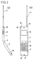
- the foldable portable telephone set includes a telephone set body which is constituted from a body section 1 in the form of a thin housing, and a cover section 2 in the form of another thin housing having a substantially same thickness as the body section 1.
- the body section 1 and the cover section are interconnected by a hinge mechanism 3 so that the cover section 2 can be opened and closed relative to the body section 1 by way of the hinge mechanism 3 to set the telephone set body into a folded condition or an open condition.
- An antenna 11, a power source switch 12, a volume button 13, a receiver 14 and a display device 15 in the form of a liquid crystal display (LCD) device are disposed on the body section 1, and a plurality of manually operable keys 16 and a transmitter 17 in the form of a microphone are disposed on the cover section 2.
- various circuit elements are disposed in the inside of the body section 1 and the cover section 2, and in addition to them, a reed switch 18 is disposed on the cover section 2, and a permanent magnet 19 is disposed at a location of the body section 1 at which it opposes to the reed switch 18 when the cover section 2 is folded on the body section 1 so that it may operate the reed switch 18.
- the reed switch 18 is positioned in the proximity of and hence in a magnetic field of the magnet 19 as seen from FIG. 2, and consequently, the reed switch 18 is switched on by the magnetic force of the magnet 19.
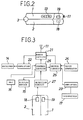
- FIG. 3 shows an internal circuit construction of the telephone set described above.
- a radio section 21 performs communications of signals with the other party side by way of the antenna 11.
- a signal received by the radio section 21 is amplified by an amplifier 22 and outputted as sound from the receiver 14.
- an audio signal from the transmitter 17 is amplified by an amplifier 23 and transmitted from the radio section 21 toward the other party side.
- a voice generator 24 generates a speech holding message and transmits it from the radio section 21.
- the signals of the transmitter 17 and the voice generator 24 are switched by means of a switch circuit 25 and selectively outputted to the radio section 21.
- a control section 26 is connected to the radio section 21, and operation information from the manually operable keys 16 is inputted to the control section 26. Also information from a detection circuit 27 which detects on or off information of the reed switch 18 is inputted is inputted to the control section 26. The switch information is utilized as information to switch the switch circuit 25. Further, various pieces of information are displayed on the display device 15.
- the telephone set can be used as an ordinary portable telephone set.
- the manually operable keys 16 are manually operated, then information of such selective manual operation of the manually operable keys 16 is inputted to the control section 26. Consequently, the control section 26 performs a predetermined call originating or terminating operation so that the telephone set enters a speaking condition with the other party side.
- the reed switch 18 disposed on the cover section 2 and the magnet 19 disposed on the body section 1 are positioned spaced away from each other, the reed switch 18 is in an off-state.
- the detection circuit 27 detects the off-state of the reed switch 18 and inputs this switch information to the control section 26. Consequently, the control section 26 switches the switch circuit 25 to the transmitter 17 side so that voice from the transmitter 17 amplified by the amplifier 23 is inputted to the radio section 21, from which it is transmitted to the other party side. On the other hand, a signal from the other party side received by the radio section 21 is amplified by the amplifier 22 and outputted as an audio signal from the receiver 14. In this speaking condition, necessary information is displayed on the display device 15.
- the cover section 2 will be closed to the body section 1 to put the telephone set into a folded condition as shown in FIG. 2. Consequently, the magnet 19 comes to the proximity of the reed switch 18, and thereupon, the reed switch 18 is put into an on-state.
- the detection circuit 27 detects the on-state of the reed switch 18 and inputs this switch information to the control section 26. Consequently, the control section 26 switches the switch circuit 25 to the voice generator 24 so that an audio message that the speech is held is generated from the voice generator 24 and transmitted to the other party side from the radio section 21. Consequently, it is notified on the other party side that the present telephone set is in a speech holding condition, and the speech is held temporarily.
- the detection circuit 27 detects this off-state and inputs this switch information to the control section 26. Consequently, the control section 26 switches the switch circuit 25 to the transmitter 17 to allow transmission, thereby recovering the speech. Simultaneously, transmission of the audio message from the voice generator 24 is stopped.
- the portable telephone set detects this and is automatically switched from a speaking condition to a speech holding condition. Consequently, the necessity of a switching operation by way of selective operation of the operation keys 16 is eliminated. Consequently, such a trouble that, upon manual operation for such switching, another key is operated in error to cause interruption of the speech, can be prevented.
- the cover section 2 is in a folded condition on the body section 1 and the operation keys 16 are covered with body section 1 and are not exposed outside. Consequently, the operation keys 16 cannot be manually operated at all, and such a trouble that that the speech holding condition is canceled or the speech is disconnected inadvertently.
- the on or off information of the reed switch 18 is detected by the detection circuit 27 and sent to the control section 26. While such on or off information of the reed switch 18 is utilized as information to switch the switch circuit 25 in the embodiment described above, the information can be utilized otherwise as information for controlling the back light or the display itself of the display device 15.
- the display 15 need not necessarily display since it is at a position at which it is not visually observed from the outside. Therefore, the signal is transmitted from the control section 26 to the display device 15 so as to erase the back light or the display itself of the display device 15.
- the back light or the display of the display device 15 is extinguished.
- a signal is sent from the control 26 to the display device 15 so that that the display device 15 may display.
- the back light or the display of the display device 15 is returned to its original condition.
- the present construction is advantageous in that the function described above can be additionally provided without modifying the circuit construction of the telephone set and besides the power dissipation can be reduced by the function.
- a switch of some other suitable construction such as, for example, a limit switch which mechanically detects an open condition of the cover section or a like switch may be utilized alternatively.
- a holding message is transmitted when the telephone set is in a speech holding condition
- a memory constituted from a RAM or a like device may be provided in place of the sound generator.
Abstract
Description
- This invention relates to a portable telephone set, and more particularly to a portable telephone set of the foldable type.
- Conventionally, a foldable telephone set of the type mentioned is constructed such that a telephone set body is divided into two sections including a body section and a cover section and they are interconnected by means of a hinge mechanism or like means so that, when the telephone set is to be used, the cover section is opened relative to the body section, but when the telephone set is not used, they are folded to facilitate transportation of the telephone set.
- By the way, in a portable telephone set in recent years, when a call to the user of the telephone set is terminated, if the user makes a response to the terminated call by operation of a key or a like means, then a speaking condition with an originating person is established. Then, when it is intended to end the speech, a key is manually operated. The portable telephone set has a response holding function for notifying, when the user cannot make a response when a call is terminated, this fact to the originating person. Also, the portable telephone set has a speech holding function for temporarily holding, when it is in a speaking condition, the speech. The response holding function and the speech holding function are performed each by way of an operation of a key.
- In the conventional portable telephone set of the construction described above, in order to cause, for example, the speech holding function to operate, it is required to operate a predetermined key during speech. However, since a key of a telephone set of the type described is small, the operability is so low that another key may be manually operated in error. If a wrong key is manually operated in this manner, then the speech may be disconnected. On the other hand, a key may be manually operated in error while the speech holding function is operating, and this may cancel holding of the speech or interrupt the speech.
- Particularly, since the body section and the cover section of a foldable portable telephone set are formed with a comparatively small thickness, switches having a comparatively small height are progressively used for keys disposed on the cover section. Where such switches are employed, not a key to be operated but another adjacent key is likely operated manually, resulting in such troubles as described above. Consequently, such troubles as described above are liable to take place.
- It is an object of the present invention to provide a foldable portable telephone set wherein switching between a speech holding condition and a speaking condition is allowed without the necessity of manual operation of a key thereby to prevent an operation of the telephone set in error.
- In order to attain the object described above, according to the present invention, there is provided a foldable portable telephone set, which comprises a body section, a cover section hinged for opening and closing movement relative to the body section, detection means for detecting an open or closed condition of the cover section relative to the body section, and means for establishing a speech holding condition when it is detected by the detection means during speech that the cover section is closed.
- The detection means may include a reed switch provided on one of the body section and the cover section, a magnet provided at a position of the other of the body section and the cover section at which the magnet is positioned adjacent the reed switch when the cover section is closed, and a detection circuit for detecting an on or off condition of the reed switch.
- The foldable portable telephone may further comprise a microphone serving as a transmitter, means for generating a speech holding message, and a switch circuit for switching between the microphone and the speech holding message generation means, the switch circuit being switched to the speech holding message side when it is detected that the cover section is closed.
- The foldable portable telephone set may further comprise a display device, and a control section for controlling the display device or back light means of the display device between an on-state and an off-state in response to detection by the detection means.
- With the foldable portable telephone set, when it is in a speaking condition, switching to a speech holding condition can be established only by manually operating the cover section into a closed condition. Consequently, otherwise possible manual operation in error is prevented. Further, since the cover section is in a folded condition when the foldable portable telephone set is in the speech holding condition, the manually operable keys will not be manually operated in error at all. Consequently, otherwise possible occurrence of cancellation of such holding condition, interruption of speech or a like trouble can be prevented.
- Further, where the means for detecting an open or closed condition of the cover section is constituted from such a reed switch, a magnet and a detection circuit as described above, the present invention can be applied to a conventional foldable portable telephone set without modifying the mechanical construction of the telephone set very much.
- Further, the switch circuit can be switched, when the cover section is closed, to transmit a speech holding message to the other party side.
- In addition, where the foldable portable telephone set is constructed such that the display device itself or the back light means for such display device is automatically switched on or off in response to an opening or closing movement of the cover section, the power dissipation of the telephone set can be reduced.
- The above and other objects, features and advantages of the present invention will become apparent from the following description and the appended claims, taken in conjunction with the accompanying drawings in which like parts or elements are denoted by like reference characters.
- FIGS. 1(a) and 1(b) are a front elevational view and a side elevational view, respectively, of a foldable portable telephone set in a speaking condition with a cover section opened showing a preferred embodiment of the present invention;
- FIG. 2 is a side elevational view of the foldable portable telephone set of FIGS. 1(a) and 1(b) but in a speech holding condition during transportation with the cover section closed; and
- FIG. 3 is a block diagram showing a circuit construction of the telephone set of FIGS. 1(a) and 1(b).
- Referring first to FIGS. 1(a), 1(b) and 2, there is shown a foldable portable telephone set to which the present invention is applied. The foldable portable telephone set includes a telephone set body which is constituted from a
body section 1 in the form of a thin housing, and acover section 2 in the form of another thin housing having a substantially same thickness as thebody section 1. Thebody section 1 and the cover section are interconnected by ahinge mechanism 3 so that thecover section 2 can be opened and closed relative to thebody section 1 by way of thehinge mechanism 3 to set the telephone set body into a folded condition or an open condition. Anantenna 11, apower source switch 12, avolume button 13, areceiver 14 and adisplay device 15 in the form of a liquid crystal display (LCD) device are disposed on thebody section 1, and a plurality of manuallyoperable keys 16 and atransmitter 17 in the form of a microphone are disposed on thecover section 2. Further, though not shown, various circuit elements are disposed in the inside of thebody section 1 and thecover section 2, and in addition to them, areed switch 18 is disposed on thecover section 2, and apermanent magnet 19 is disposed at a location of thebody section 1 at which it opposes to thereed switch 18 when thecover section 2 is folded on thebody section 1 so that it may operate thereed switch 18. Here, when thecover section 2 is folded on thebody section 1, thereed switch 18 is positioned in the proximity of and hence in a magnetic field of themagnet 19 as seen from FIG. 2, and consequently, thereed switch 18 is switched on by the magnetic force of themagnet 19. - FIG. 3 shows an internal circuit construction of the telephone set described above. Referring now to FIG. 3, a
radio section 21 performs communications of signals with the other party side by way of theantenna 11. A signal received by theradio section 21 is amplified by anamplifier 22 and outputted as sound from thereceiver 14. On the other hand, an audio signal from thetransmitter 17 is amplified by anamplifier 23 and transmitted from theradio section 21 toward the other party side. Avoice generator 24 generates a speech holding message and transmits it from theradio section 21. The signals of thetransmitter 17 and thevoice generator 24 are switched by means of aswitch circuit 25 and selectively outputted to theradio section 21. - A
control section 26 is connected to theradio section 21, and operation information from the manuallyoperable keys 16 is inputted to thecontrol section 26. Also information from adetection circuit 27 which detects on or off information of thereed switch 18 is inputted is inputted to thecontrol section 26. The switch information is utilized as information to switch theswitch circuit 25. Further, various pieces of information are displayed on thedisplay device 15. - Operation of the foldable portable telephone set having the construction described above will be described subsequently. When the
body section 1 and thecover section 2 are opened by way of thehinge mechanism 3 as shown in FIG. 1, the telephone set can be used as an ordinary portable telephone set. In particular, if the manuallyoperable keys 16 are manually operated, then information of such selective manual operation of the manuallyoperable keys 16 is inputted to thecontrol section 26. Consequently, thecontrol section 26 performs a predetermined call originating or terminating operation so that the telephone set enters a speaking condition with the other party side. In this instance, since thereed switch 18 disposed on thecover section 2 and themagnet 19 disposed on thebody section 1 are positioned spaced away from each other, thereed switch 18 is in an off-state. Thedetection circuit 27 detects the off-state of thereed switch 18 and inputs this switch information to thecontrol section 26. Consequently, thecontrol section 26 switches theswitch circuit 25 to thetransmitter 17 side so that voice from thetransmitter 17 amplified by theamplifier 23 is inputted to theradio section 21, from which it is transmitted to the other party side. On the other hand, a signal from the other party side received by theradio section 21 is amplified by theamplifier 22 and outputted as an audio signal from thereceiver 14. In this speaking condition, necessary information is displayed on thedisplay device 15. - Then, if it is intended to change the condition of the telephone set from the speaking condition to a speech holding condition, then the
cover section 2 will be closed to thebody section 1 to put the telephone set into a folded condition as shown in FIG. 2. Consequently, themagnet 19 comes to the proximity of thereed switch 18, and thereupon, thereed switch 18 is put into an on-state. Thedetection circuit 27 detects the on-state of thereed switch 18 and inputs this switch information to thecontrol section 26. Consequently, thecontrol section 26 switches theswitch circuit 25 to thevoice generator 24 so that an audio message that the speech is held is generated from thevoice generator 24 and transmitted to the other party side from theradio section 21. Consequently, it is notified on the other party side that the present telephone set is in a speech holding condition, and the speech is held temporarily. - Thereafter, when the
cover section 2 is opened again to restore the condition of the telephone set shown in FIG. 1 in order to resume the speech, then since thereed switch 18 is put back into an off-state, thedetection circuit 27 detects this off-state and inputs this switch information to thecontrol section 26. Consequently, thecontrol section 26 switches theswitch circuit 25 to thetransmitter 17 to allow transmission, thereby recovering the speech. Simultaneously, transmission of the audio message from thevoice generator 24 is stopped. - In this manner, if the
cover section 2 is folded during speech, then the portable telephone set detects this and is automatically switched from a speaking condition to a speech holding condition. Consequently, the necessity of a switching operation by way of selective operation of theoperation keys 16 is eliminated. Consequently, such a trouble that, upon manual operation for such switching, another key is operated in error to cause interruption of the speech, can be prevented. Further, in a speech holding condition of the telephone set, thecover section 2 is in a folded condition on thebody section 1 and theoperation keys 16 are covered withbody section 1 and are not exposed outside. Consequently, theoperation keys 16 cannot be manually operated at all, and such a trouble that that the speech holding condition is canceled or the speech is disconnected inadvertently. - It is possible to add a function of erasing the back light or the display itself of the
display device 15, which is formed from liquid crystal, making use of the circuit described above with reference to FIG. 3. - This can be applied without modifying the construction of the block diagram of FIG. 3 in which the internal circuit construction of the telephone set is shown. Upon opening or closing movement of the telephone set, the on or off information of the
reed switch 18 is detected by thedetection circuit 27 and sent to thecontrol section 26. While such on or off information of thereed switch 18 is utilized as information to switch theswitch circuit 25 in the embodiment described above, the information can be utilized otherwise as information for controlling the back light or the display itself of thedisplay device 15. When the telephone set is in a closed condition, thedisplay 15 need not necessarily display since it is at a position at which it is not visually observed from the outside. Therefore, the signal is transmitted from thecontrol section 26 to thedisplay device 15 so as to erase the back light or the display itself of thedisplay device 15. When the signal represents that the telephone set is closed, the back light or the display of thedisplay device 15 is extinguished. On the contrary when the telephone set is opened, a signal is sent from thecontrol 26 to thedisplay device 15 so that that thedisplay device 15 may display. In response to the signal, the back light or the display of thedisplay device 15 is returned to its original condition. - The present construction is advantageous in that the function described above can be additionally provided without modifying the circuit construction of the telephone set and besides the power dissipation can be reduced by the function.
- It is to be noted that, while the reed switch is provided on the cover section and the magnet is provided on the body section in the embodiment described above, the arrangement of them may be reversed relative to each other. Further, while the open or closed condition of the cover section is detected by means of the reed switch in the embodiment described above, a switch of some other suitable construction such as, for example, a limit switch which mechanically detects an open condition of the cover section or a like switch may be utilized alternatively.
- Further, while, in the embodiment described above, a holding message is transmitted when the telephone set is in a speech holding condition, it is otherwise possible to construct the telephone set so that mere holding sound, a melody stored in advance or some other suitable sound is transmitted. In this instance, a memory constituted from a RAM or a like device may be provided in place of the sound generator.
- Having now fully described the invention, it will be apparent to one of ordinary skill in the art that many changes and modifications can be made thereto without departing from the spirit and scope of the invention as set forth herein.
Claims (4)
- A foldable portable telephone set which includes a body section and a cover section hinged for opening and closing movement relative to said body section, characterized in that it comprises
detection means for detecting an open or closed condition of said cover section relative to said body section; and
means for establishing a speech holding condition when it is detected by said detection means during speech that said cover section is closed. - A foldable portable telephone set as set forth in claim 1, characterized in that said detection means includes a reed switch provided on one of said body section and said cover section, a magnet provided at a position of the other of said body section and said cover section at which said magnet is positioned adjacent said reed switch when said cover section is closed, and a detection circuit for detecting an on or off condition of said reed switch.
- A foldable portable telephone set as set forth in claim 1 or 2, characterized in that it further comprises a microphone serving as a transmitter, means for generating a speech holding message, and a switch circuit for switching between said microphone and said speech holding message generation means, said switch circuit being switched to the speech holding message side when it is detected that said cover section is closed.
- A foldable portable telephone set as set forth in claim 1, 2 or 3, characterized in that it further comprises a display device, and a control section for controlling said display device or back light means of said display device between an on-state and an off-state in response to detection by said detection means.
Applications Claiming Priority (3)
| Application Number | Priority Date | Filing Date | Title |
|---|---|---|---|
| JP5178526A JP2833964B2 (en) | 1993-06-28 | 1993-06-28 | Foldable mobile phone |
| JP17852693 | 1993-06-28 | ||
| JP178526/93 | 1993-06-28 |
Publications (3)
| Publication Number | Publication Date |
|---|---|
| EP0631416A2 true EP0631416A2 (en) | 1994-12-28 |
| EP0631416A3 EP0631416A3 (en) | 1995-09-20 |
| EP0631416B1 EP0631416B1 (en) | 2002-09-18 |
Family
ID=16050021
Family Applications (1)
| Application Number | Title | Priority Date | Filing Date |
|---|---|---|---|
| EP94109993A Expired - Lifetime EP0631416B1 (en) | 1993-06-28 | 1994-06-28 | Foldable portable telephone set |
Country Status (6)
| Country | Link |
|---|---|
| US (1) | US5493690A (en) |
| EP (1) | EP0631416B1 (en) |
| JP (1) | JP2833964B2 (en) |
| AU (1) | AU677056B2 (en) |
| CA (1) | CA2126844C (en) |
| DE (1) | DE69431382T2 (en) |
Cited By (13)
| Publication number | Priority date | Publication date | Assignee | Title |
|---|---|---|---|---|
| WO1998010572A1 (en) * | 1996-09-06 | 1998-03-12 | Siemens Aktiengesellschaft | Mobile telephone terminal |
| EP0944219A2 (en) * | 1998-03-18 | 1999-09-22 | Nokia Mobile Phones Ltd. | Telescopic telephone |
| WO2000017901A1 (en) * | 1998-09-18 | 2000-03-30 | Allegro Microsystems, Inc. | Magnetic pole insensitive switch circuit |
| EP1187155A2 (en) * | 2000-09-12 | 2002-03-13 | Inventec Electronics (Nanjing) Co., Ltd. | Fixing structure for input keys |
| US6522131B1 (en) | 1999-09-17 | 2003-02-18 | Melexis Nv | Multi-mode hall effect sensor for determining position and timing parameters of a gear wheel |
| EP1376208A1 (en) * | 2002-06-20 | 2004-01-02 | Nec Corporation | Display Device and Portable Terminal Apparatus |
| FR2853477A1 (en) * | 2003-03-24 | 2004-10-08 | Inventec Appliances Corp | Mechanism for switching flip-type cellular phone to digital camera, aligns magnet with reed switch and enables control circuit to switch cellular phone to camera mode, when display is rotated to specified angle and folded onto keypad |
| DE19827833B4 (en) * | 1997-06-30 | 2006-07-13 | Motorola, Inc. (n.d.Ges.d. Staates Delaware), Schaumburg | Lockable communication device |
| US7624357B2 (en) | 2000-02-18 | 2009-11-24 | Vtech Telecommunications Limited | Mobile telephone with improved man machine interface |
| US7965076B2 (en) | 2007-06-04 | 2011-06-21 | Melexis Nv, Microelectronic Integrated Systems | Magnetic field orientation sensor |
| US8552721B2 (en) | 2007-12-07 | 2013-10-08 | Melexis Technologies Nv | Hall sensor array |
| US10385964B2 (en) | 2016-06-08 | 2019-08-20 | Allegro Microsystems, Llc | Enhanced neutral gear sensor |
| US10739164B2 (en) | 2017-01-27 | 2020-08-11 | Allegro Microsystems, Llc | Circuit for detecting motion of an object |
Families Citing this family (88)
| Publication number | Priority date | Publication date | Assignee | Title |
|---|---|---|---|---|
| JP2826469B2 (en) * | 1994-05-11 | 1998-11-18 | 日本電気株式会社 | Mobile phone |
| JP2658906B2 (en) * | 1994-09-22 | 1997-09-30 | 日本電気株式会社 | Automatic open folding mobile phone |
| EP0883957B1 (en) | 1996-02-26 | 2006-06-07 | Nokia Corporation | Radio telephone |
| US6073027A (en) * | 1996-08-29 | 2000-06-06 | Bellsouth Corporation | Portable radiotelephone with sliding cover and automatic antenna extension |
| US6035211A (en) * | 1996-12-19 | 2000-03-07 | Ericsson Inc. | Dual use speaker for both voice communication and signalling |
| JP2944582B2 (en) * | 1997-06-25 | 1999-09-06 | 埼玉日本電気株式会社 | Foldable mobile phone |
| JP3130851B2 (en) | 1997-12-09 | 2001-01-31 | 埼玉日本電気株式会社 | Foldable mobile phone |
| WO1999048264A1 (en) * | 1998-03-19 | 1999-09-23 | Samsung Electronics Co., Ltd. | Folding communication device |
| USD410929S (en) * | 1998-03-23 | 1999-06-15 | Motorola, Inc. | Top housing for a foldable portable telephone |
| USD434402S (en) * | 1998-04-22 | 2000-11-28 | Samsung Electronics Co., Ltd. | Cellular phone |
| US6292674B1 (en) * | 1998-08-05 | 2001-09-18 | Ericsson, Inc. | One-handed control for wireless telephone |
| USD408402S (en) * | 1998-08-18 | 1999-04-20 | Motorola, Inc. | Cellular telephone housing |
| KR100270381B1 (en) | 1998-09-24 | 2000-11-01 | 윤종용 | Call maintaining and disconnecting method during data communication in flip type telephone set |
| US6151486A (en) * | 1998-10-30 | 2000-11-21 | Ericsson Inc. | Magnetic latch and release device and radiotelephones incorporating same |
| KR100504041B1 (en) * | 1998-12-14 | 2005-09-26 | 엘지전자 주식회사 | Flip-type telephone terminal equipped with a call holding button and the call processing method? |
| GB2346759B (en) * | 1999-02-12 | 2003-06-18 | Nokia Mobile Phones Ltd | Radiotelephone |
| KR100301862B1 (en) * | 1999-03-18 | 2001-09-26 | 서평원 | Apparatus and Method for controlling Light Emitting Diode of Mobile phone |
| USD424557S (en) * | 1999-06-18 | 2000-05-09 | Motorola, Inc. | Cellular telephone housing |
| USD419155S (en) * | 1999-07-01 | 2000-01-18 | Motorola, Inc. | Cellular telephone housing |
| JP3425904B2 (en) | 1999-09-22 | 2003-07-14 | エヌイーシーモバイリング株式会社 | Mobile phone device and internet site access method used therefor |
| TW536903B (en) * | 2000-05-03 | 2003-06-11 | Benq Corp | Sensor for detecting the state of a cover of a cellular phone |
| JP3448547B2 (en) * | 2000-05-12 | 2003-09-22 | 三洋電機株式会社 | Foldable mobile phone |
| US6801796B2 (en) * | 2000-05-31 | 2004-10-05 | Nokia Mobile Phones Ltd. | Soft keys for a mobile communications device having moveable panels |
| US6429817B1 (en) | 2000-10-03 | 2002-08-06 | Bellsouth Intellectual Property Corporation | Retractable antenna for portable telephone |
| WO2002039600A2 (en) * | 2000-11-07 | 2002-05-16 | Research In Motion Limited | Communication device with multiple detachable communication modules |
| WO2002041611A1 (en) * | 2000-11-20 | 2002-05-23 | Helios Co., Ltd. | Communication terminal apparatus, automatic line connection method, information storing medium and program |
| JP2002304136A (en) * | 2001-01-17 | 2002-10-18 | Seiko Epson Corp | Electronic equipment provided with organic electroluminescence display |
| JP2002314658A (en) * | 2001-04-16 | 2002-10-25 | Nec Corp | Folding portable terminal |
| KR20020093236A (en) * | 2001-06-07 | 2002-12-16 | 세원 텔레콤 주식회사 | Folder open and close sensing device using of magnetic force of speaker for folder-type terminal |
| US7110525B1 (en) | 2001-06-25 | 2006-09-19 | Toby Heller | Agent training sensitive call routing system |
| US7372952B1 (en) | 2002-03-07 | 2008-05-13 | Wai Wu | Telephony control system with intelligent call routing |
| JP3961397B2 (en) * | 2002-10-29 | 2007-08-22 | 京セラ株式会社 | Mobile terminal device |
| US9818136B1 (en) | 2003-02-05 | 2017-11-14 | Steven M. Hoffberg | System and method for determining contingent relevance |
| US7676034B1 (en) | 2003-03-07 | 2010-03-09 | Wai Wu | Method and system for matching entities in an auction |
| JP2005026858A (en) * | 2003-06-30 | 2005-01-27 | Sharp Corp | Portable information processing unit |
| US20050054303A1 (en) * | 2003-09-05 | 2005-03-10 | Jeppe Goltermann | Open/closed detection for an electronic device |
| JP3816475B2 (en) * | 2003-09-30 | 2006-08-30 | 株式会社東芝 | Portable wireless communication device |
| KR100608731B1 (en) * | 2003-12-22 | 2006-08-04 | 엘지전자 주식회사 | Swible mobile phone and communicating method using the same |
| US7761167B2 (en) | 2004-06-10 | 2010-07-20 | Medtronic Urinary Solutions, Inc. | Systems and methods for clinician control of stimulation systems |
| US8874477B2 (en) | 2005-10-04 | 2014-10-28 | Steven Mark Hoffberg | Multifactorial optimization system and method |
| US8300798B1 (en) | 2006-04-03 | 2012-10-30 | Wai Wu | Intelligent communication routing system and method |
| US7593524B2 (en) * | 2006-11-27 | 2009-09-22 | Nokia Corporation | Hinge arrangement |
| CN101541148B (en) * | 2008-03-18 | 2011-01-19 | 华硕电脑股份有限公司 | Magnetic fixing structure and electronic device using same |
| JP5396775B2 (en) * | 2008-08-26 | 2014-01-22 | カシオ計算機株式会社 | Server device, client device, server control program, and client control program for server-based computing system |
| CN102378503A (en) * | 2010-08-06 | 2012-03-14 | 鸿富锦精密工业(深圳)有限公司 | Electronic device combination |
| US8531404B2 (en) * | 2010-10-04 | 2013-09-10 | Dresser, Inc. | Display assembly and a fuel dispensing unit |
| US8786279B2 (en) | 2011-02-25 | 2014-07-22 | Allegro Microsystems, Llc | Circuit and method for processing signals generated by a plurality of sensors |
| US9062990B2 (en) | 2011-02-25 | 2015-06-23 | Allegro Microsystems, Llc | Circular vertical hall magnetic field sensing element and method with a plurality of continuous output signals |
| US8729890B2 (en) | 2011-04-12 | 2014-05-20 | Allegro Microsystems, Llc | Magnetic angle and rotation speed sensor with continuous and discontinuous modes of operation based on rotation speed of a target object |
| US8860410B2 (en) | 2011-05-23 | 2014-10-14 | Allegro Microsystems, Llc | Circuits and methods for processing a signal generated by a plurality of measuring devices |
| US8890518B2 (en) | 2011-06-08 | 2014-11-18 | Allegro Microsystems, Llc | Arrangements for self-testing a circular vertical hall (CVH) sensing element and/or for self-testing a magnetic field sensor that uses a circular vertical hall (CVH) sensing element |
| US8793085B2 (en) | 2011-08-19 | 2014-07-29 | Allegro Microsystems, Llc | Circuits and methods for automatically adjusting a magnetic field sensor in accordance with a speed of rotation sensed by the magnetic field sensor |
| US8922206B2 (en) | 2011-09-07 | 2014-12-30 | Allegro Microsystems, Llc | Magnetic field sensing element combining a circular vertical hall magnetic field sensing element with a planar hall element |
| US9285438B2 (en) | 2011-09-28 | 2016-03-15 | Allegro Microsystems, Llc | Circuits and methods for processing signals generated by a plurality of magnetic field sensing elements |
| US9046383B2 (en) | 2012-01-09 | 2015-06-02 | Allegro Microsystems, Llc | Systems and methods that use magnetic field sensors to identify positions of a gear shift lever |
| US9182456B2 (en) | 2012-03-06 | 2015-11-10 | Allegro Microsystems, Llc | Magnetic field sensor for sensing rotation of an object |
| US10215550B2 (en) | 2012-05-01 | 2019-02-26 | Allegro Microsystems, Llc | Methods and apparatus for magnetic sensors having highly uniform magnetic fields |
| US9606190B2 (en) | 2012-12-21 | 2017-03-28 | Allegro Microsystems, Llc | Magnetic field sensor arrangements and associated methods |
| US8749005B1 (en) | 2012-12-21 | 2014-06-10 | Allegro Microsystems, Llc | Magnetic field sensor and method of fabricating a magnetic field sensor having a plurality of vertical hall elements arranged in at least a portion of a polygonal shape |
| US9417295B2 (en) | 2012-12-21 | 2016-08-16 | Allegro Microsystems, Llc | Circuits and methods for processing signals generated by a circular vertical hall (CVH) sensing element in the presence of a multi-pole magnet |
| US9548443B2 (en) | 2013-01-29 | 2017-01-17 | Allegro Microsystems, Llc | Vertical Hall Effect element with improved sensitivity |
| US9377285B2 (en) | 2013-02-13 | 2016-06-28 | Allegro Microsystems, Llc | Magnetic field sensor and related techniques that provide varying current spinning phase sequences of a magnetic field sensing element |
| US9389060B2 (en) | 2013-02-13 | 2016-07-12 | Allegro Microsystems, Llc | Magnetic field sensor and related techniques that provide an angle error correction module |
| US9099638B2 (en) | 2013-03-15 | 2015-08-04 | Allegro Microsystems, Llc | Vertical hall effect element with structures to improve sensitivity |
| WO2014189733A1 (en) | 2013-05-24 | 2014-11-27 | Allegro Microsystems, Llc | Magnetic field sensor for detecting a magnetic field in any direction above thresholds |
| US9733106B2 (en) | 2013-05-24 | 2017-08-15 | Allegro Microsystems, Llc | Magnetic field sensor to detect a magnitude of a magnetic field in any direction |
| US9312473B2 (en) | 2013-09-30 | 2016-04-12 | Allegro Microsystems, Llc | Vertical hall effect sensor |
| US10120042B2 (en) | 2013-12-23 | 2018-11-06 | Allegro Microsystems, Llc | Magnetic field sensor and related techniques that inject a synthesized error correction signal into a signal channel to result in reduced error |
| US9574867B2 (en) | 2013-12-23 | 2017-02-21 | Allegro Microsystems, Llc | Magnetic field sensor and related techniques that inject an error correction signal into a signal channel to result in reduced error |
| US9547048B2 (en) | 2014-01-14 | 2017-01-17 | Allegro Micosystems, LLC | Circuit and method for reducing an offset component of a plurality of vertical hall elements arranged in a circle |
| US9753097B2 (en) | 2014-05-05 | 2017-09-05 | Allegro Microsystems, Llc | Magnetic field sensors and associated methods with reduced offset and improved accuracy |
| US9448288B2 (en) | 2014-05-20 | 2016-09-20 | Allegro Microsystems, Llc | Magnetic field sensor with improved accuracy resulting from a digital potentiometer |
| US9823092B2 (en) | 2014-10-31 | 2017-11-21 | Allegro Microsystems, Llc | Magnetic field sensor providing a movement detector |
| AU2015343339A1 (en) | 2014-11-03 | 2017-06-15 | Genentech, Inc. | Methods and biomarkers for predicting efficacy and evaluation of an OX40 agonist treatment |
| US9638766B2 (en) | 2014-11-24 | 2017-05-02 | Allegro Microsystems, Llc | Magnetic field sensor with improved accuracy resulting from a variable potentiometer and a gain circuit |
| US9684042B2 (en) | 2015-02-27 | 2017-06-20 | Allegro Microsystems, Llc | Magnetic field sensor with improved accuracy and method of obtaining improved accuracy with a magnetic field sensor |
| US11163022B2 (en) | 2015-06-12 | 2021-11-02 | Allegro Microsystems, Llc | Magnetic field sensor for angle detection with a phase-locked loop |
| US9739848B1 (en) | 2016-02-01 | 2017-08-22 | Allegro Microsystems, Llc | Circular vertical hall (CVH) sensing element with sliding integration |
| US10481220B2 (en) | 2016-02-01 | 2019-11-19 | Allegro Microsystems, Llc | Circular vertical hall (CVH) sensing element with signal processing and arctangent function |
| US9739847B1 (en) | 2016-02-01 | 2017-08-22 | Allegro Microsystems, Llc | Circular vertical hall (CVH) sensing element with signal processing |
| US10585147B2 (en) | 2016-06-14 | 2020-03-10 | Allegro Microsystems, Llc | Magnetic field sensor having error correction |
| US10495701B2 (en) | 2017-03-02 | 2019-12-03 | Allegro Microsystems, Llc | Circular vertical hall (CVH) sensing element with DC offset removal |
| WO2018193945A1 (en) * | 2017-04-17 | 2018-10-25 | シャープ株式会社 | Portable terminal, control method, and program |
| US10823586B2 (en) | 2018-12-26 | 2020-11-03 | Allegro Microsystems, Llc | Magnetic field sensor having unequally spaced magnetic field sensing elements |
| US11280637B2 (en) | 2019-11-14 | 2022-03-22 | Allegro Microsystems, Llc | High performance magnetic angle sensor |
| US11237020B2 (en) | 2019-11-14 | 2022-02-01 | Allegro Microsystems, Llc | Magnetic field sensor having two rows of magnetic field sensing elements for measuring an angle of rotation of a magnet |
| US11802922B2 (en) | 2021-01-13 | 2023-10-31 | Allegro Microsystems, Llc | Circuit for reducing an offset component of a plurality of vertical hall elements arranged in one or more circles |
| US11473935B1 (en) | 2021-04-16 | 2022-10-18 | Allegro Microsystems, Llc | System and related techniques that provide an angle sensor for sensing an angle of rotation of a ferromagnetic screw |
Citations (3)
| Publication number | Priority date | Publication date | Assignee | Title |
|---|---|---|---|---|
| EP0275193A2 (en) * | 1987-01-16 | 1988-07-20 | Nec Corporation | Telephone having receive call indicating function and mute/light key |
| WO1991007836A1 (en) * | 1989-11-20 | 1991-05-30 | Motorola, Inc. | Communications device with movable element control interface |
| WO1992017974A1 (en) * | 1991-03-28 | 1992-10-15 | Motorola, Inc. | Hinge apparatus for foldable radiotelephones |
Family Cites Families (13)
| Publication number | Priority date | Publication date | Assignee | Title |
|---|---|---|---|---|
| GB2087686B (en) * | 1980-10-17 | 1984-05-31 | Lambda Tele Equipment Ltd | One piece telephone |
| JPS59135960A (en) * | 1983-01-25 | 1984-08-04 | Fujitsu Ltd | Hook switch changeover device of folded type handset in telephone set or the like |
| JPS6095889A (en) * | 1983-10-28 | 1985-05-29 | シャープ株式会社 | Thin film el element |
| CA1243385A (en) * | 1984-06-28 | 1988-10-18 | Iwao Hasegawa | Electronic private branch exchanges |
| JPS61208349A (en) * | 1985-03-12 | 1986-09-16 | Nec Corp | Telephone handset with holding switch |
| US4924193A (en) * | 1987-01-30 | 1990-05-08 | Nec Corporation | Volume control circuit for use in portable telephone or the like |
| JPH0793300B2 (en) * | 1987-07-20 | 1995-10-09 | 株式会社日立製作所 | Wiring forming method and apparatus thereof |
| JPH01279659A (en) * | 1988-04-30 | 1989-11-09 | Nec Home Electron Ltd | Telephone set |
| US5214688A (en) * | 1990-06-05 | 1993-05-25 | Inventions, Inc. | Method and apparatus for dynamic and interdependent processing of inbound calls and outbound calls |
| JPH0491541A (en) * | 1990-08-07 | 1992-03-25 | Fujitsu Ltd | Handset for telephone set |
| JP3109089B2 (en) * | 1990-08-31 | 2000-11-13 | 日本電気株式会社 | Foldable mobile phone |
| JPH0591172A (en) * | 1991-09-30 | 1993-04-09 | Casio Comput Co Ltd | Portable telephone set |
| JP2931706B2 (en) * | 1991-09-30 | 1999-08-09 | 松下電器産業株式会社 | Cordless telephone equipment |
-
1993
- 1993-06-28 JP JP5178526A patent/JP2833964B2/en not_active Expired - Lifetime
-
1994
- 1994-06-27 CA CA002126844A patent/CA2126844C/en not_active Expired - Fee Related
- 1994-06-27 AU AU65996/94A patent/AU677056B2/en not_active Expired
- 1994-06-28 US US08/266,569 patent/US5493690A/en not_active Expired - Lifetime
- 1994-06-28 EP EP94109993A patent/EP0631416B1/en not_active Expired - Lifetime
- 1994-06-28 DE DE69431382T patent/DE69431382T2/en not_active Expired - Lifetime
Patent Citations (3)
| Publication number | Priority date | Publication date | Assignee | Title |
|---|---|---|---|---|
| EP0275193A2 (en) * | 1987-01-16 | 1988-07-20 | Nec Corporation | Telephone having receive call indicating function and mute/light key |
| WO1991007836A1 (en) * | 1989-11-20 | 1991-05-30 | Motorola, Inc. | Communications device with movable element control interface |
| WO1992017974A1 (en) * | 1991-03-28 | 1992-10-15 | Motorola, Inc. | Hinge apparatus for foldable radiotelephones |
Non-Patent Citations (1)
| Title |
|---|
| TELCOM REPORT, vol. 10, no. 2, 1987 M]NCHEN, pages 130-137, WOLF 'AUCH OHNE SCHNUR "AUF DRAHT"' * |
Cited By (28)
| Publication number | Priority date | Publication date | Assignee | Title |
|---|---|---|---|---|
| WO1998010572A1 (en) * | 1996-09-06 | 1998-03-12 | Siemens Aktiengesellschaft | Mobile telephone terminal |
| DE19827833B4 (en) * | 1997-06-30 | 2006-07-13 | Motorola, Inc. (n.d.Ges.d. Staates Delaware), Schaumburg | Lockable communication device |
| US6961593B1 (en) | 1998-03-18 | 2005-11-01 | Nokia Mobile Phones, Ltd | Telescopic telephone |
| EP0944219A2 (en) * | 1998-03-18 | 1999-09-22 | Nokia Mobile Phones Ltd. | Telescopic telephone |
| US7519404B2 (en) | 1998-03-18 | 2009-04-14 | Nokia Corporation | Telescopic telephone |
| EP1833231A3 (en) * | 1998-03-18 | 2007-12-12 | Nokia Corporation | Telescopic telephone |
| EP1833231A2 (en) | 1998-03-18 | 2007-09-12 | Nokia Corporation | Telescopic telephone |
| EP0944219A3 (en) * | 1998-03-18 | 2003-08-06 | Nokia Corporation | Telescopic telephone |
| US6622012B2 (en) | 1998-09-18 | 2003-09-16 | Allegro Microsystems, Inc. | Magnetic pole insensitive switch circuit |
| US7307824B2 (en) | 1998-09-18 | 2007-12-11 | Allegro Microsystems, Inc. | Magnetic pole insensitive switch circuit |
| EP1487000A1 (en) * | 1998-09-18 | 2004-12-15 | Allegro Microsystems Inc. | Magnetic pole insensitive switch |
| US7085119B2 (en) | 1998-09-18 | 2006-08-01 | Allegro Microsystems, Inc. | Magnetic pole insensitive switch circuit |
| WO2000017901A1 (en) * | 1998-09-18 | 2000-03-30 | Allegro Microsystems, Inc. | Magnetic pole insensitive switch circuit |
| US6356741B1 (en) | 1998-09-18 | 2002-03-12 | Allegro Microsystems, Inc. | Magnetic pole insensitive switch circuit |
| US6522131B1 (en) | 1999-09-17 | 2003-02-18 | Melexis Nv | Multi-mode hall effect sensor for determining position and timing parameters of a gear wheel |
| US8812057B2 (en) | 2000-02-18 | 2014-08-19 | Motorola Mobility Llc | Mobile telephone with improved man machine interface |
| US8160651B2 (en) | 2000-02-18 | 2012-04-17 | Motorola Mobility, Inc. | Mobile telephone with improved man machine interface |
| US7624357B2 (en) | 2000-02-18 | 2009-11-24 | Vtech Telecommunications Limited | Mobile telephone with improved man machine interface |
| EP1187155A2 (en) * | 2000-09-12 | 2002-03-13 | Inventec Electronics (Nanjing) Co., Ltd. | Fixing structure for input keys |
| EP1187155A3 (en) * | 2000-09-12 | 2004-03-24 | Inventec Electronics (Nanjing) Co., Ltd. | Fixing structure for input keys |
| US6882865B2 (en) | 2000-09-12 | 2005-04-19 | Inventec Electronics (Nanjing) | Fixing structure for input keys |
| US7197338B2 (en) | 2002-06-20 | 2007-03-27 | Nec Corporation | Display device and portable terminal apparatus |
| EP1376208A1 (en) * | 2002-06-20 | 2004-01-02 | Nec Corporation | Display Device and Portable Terminal Apparatus |
| FR2853477A1 (en) * | 2003-03-24 | 2004-10-08 | Inventec Appliances Corp | Mechanism for switching flip-type cellular phone to digital camera, aligns magnet with reed switch and enables control circuit to switch cellular phone to camera mode, when display is rotated to specified angle and folded onto keypad |
| US7965076B2 (en) | 2007-06-04 | 2011-06-21 | Melexis Nv, Microelectronic Integrated Systems | Magnetic field orientation sensor |
| US8552721B2 (en) | 2007-12-07 | 2013-10-08 | Melexis Technologies Nv | Hall sensor array |
| US10385964B2 (en) | 2016-06-08 | 2019-08-20 | Allegro Microsystems, Llc | Enhanced neutral gear sensor |
| US10739164B2 (en) | 2017-01-27 | 2020-08-11 | Allegro Microsystems, Llc | Circuit for detecting motion of an object |
Also Published As
| Publication number | Publication date |
|---|---|
| AU6599694A (en) | 1995-01-05 |
| JP2833964B2 (en) | 1998-12-09 |
| CA2126844C (en) | 1998-11-17 |
| US5493690A (en) | 1996-02-20 |
| JPH0715493A (en) | 1995-01-17 |
| EP0631416B1 (en) | 2002-09-18 |
| CA2126844A1 (en) | 1994-12-29 |
| DE69431382T2 (en) | 2003-01-23 |
| AU677056B2 (en) | 1997-04-10 |
| EP0631416A3 (en) | 1995-09-20 |
| DE69431382D1 (en) | 2002-10-24 |
Similar Documents
| Publication | Publication Date | Title |
|---|---|---|
| EP0631416B1 (en) | Foldable portable telephone set | |
| US7336977B2 (en) | Communication apparatus | |
| EP0678987B1 (en) | Portable radio with display | |
| JP3074944B2 (en) | Mobile phone | |
| US7089040B2 (en) | Portable radio communication apparatus | |
| US5638441A (en) | Portable telephone apparatus with rotatable cover allowing enhanced option key access | |
| US7321789B2 (en) | Folding information processor | |
| US7031743B2 (en) | Foldable portable communication terminal device | |
| EP0607038B1 (en) | Portable telephone | |
| US20050049011A1 (en) | Power control apparatus of a foldable portable mobile terminal | |
| US7096050B2 (en) | Portable telephone | |
| US20040204012A1 (en) | Folding mobile phone | |
| KR200229560Y1 (en) | A portable telephone with air bag | |
| JP3443366B2 (en) | Communication device | |
| JPH10145469A (en) | Portable telephone set | |
| JP3751811B2 (en) | Foldable mobile phone | |
| JPH1117609A (en) | Composite radio portable terminal equipment | |
| KR20040077192A (en) | Upper-folder rotation type mobile phone having dual speaker and for switching thereof | |
| JP2001136253A (en) | Folding portable telephone set | |
| KR200214674Y1 (en) | Mobile communication terminal having a key for manner mode on the outer | |
| JP2000151768A (en) | Portable telephone set | |
| JP2000341379A (en) | Portable phone | |
| KR200225629Y1 (en) | The folder type portable telephone | |
| JP2000244612A (en) | Portable information terminal equipped with incoming automatic switch function | |
| JP2002101172A (en) | Radio information terminal device |
Legal Events
| Date | Code | Title | Description |
|---|---|---|---|
| PUAI | Public reference made under article 153(3) epc to a published international application that has entered the european phase |
Free format text: ORIGINAL CODE: 0009012 |
|
| AK | Designated contracting states |
Kind code of ref document: A2 Designated state(s): DE GB |
|
| PUAL | Search report despatched |
Free format text: ORIGINAL CODE: 0009013 |
|
| AK | Designated contracting states |
Kind code of ref document: A3 Designated state(s): DE GB |
|
| 17P | Request for examination filed |
Effective date: 19950810 |
|
| 17Q | First examination report despatched |
Effective date: 19991119 |
|
| GRAG | Despatch of communication of intention to grant |
Free format text: ORIGINAL CODE: EPIDOS AGRA |
|
| GRAG | Despatch of communication of intention to grant |
Free format text: ORIGINAL CODE: EPIDOS AGRA |
|
| GRAG | Despatch of communication of intention to grant |
Free format text: ORIGINAL CODE: EPIDOS AGRA |
|
| GRAH | Despatch of communication of intention to grant a patent |
Free format text: ORIGINAL CODE: EPIDOS IGRA |
|
| GRAH | Despatch of communication of intention to grant a patent |
Free format text: ORIGINAL CODE: EPIDOS IGRA |
|
| GRAA | (expected) grant |
Free format text: ORIGINAL CODE: 0009210 |
|
| AK | Designated contracting states |
Kind code of ref document: B1 Designated state(s): DE GB |
|
| REG | Reference to a national code |
Ref country code: GB Ref legal event code: FG4D |
|
| REF | Corresponds to: |
Ref document number: 69431382 Country of ref document: DE Date of ref document: 20021024 |
|
| PLBE | No opposition filed within time limit |
Free format text: ORIGINAL CODE: 0009261 |
|
| STAA | Information on the status of an ep patent application or granted ep patent |
Free format text: STATUS: NO OPPOSITION FILED WITHIN TIME LIMIT |
|
| 26N | No opposition filed |
Effective date: 20030619 |
|
| PGFP | Annual fee paid to national office [announced via postgrant information from national office to epo] |
Ref country code: GB Payment date: 20130626 Year of fee payment: 20 Ref country code: DE Payment date: 20130626 Year of fee payment: 20 |
|
| REG | Reference to a national code |
Ref country code: DE Ref legal event code: R071 Ref document number: 69431382 Country of ref document: DE |
|
| REG | Reference to a national code |
Ref country code: DE Ref legal event code: R071 Ref document number: 69431382 Country of ref document: DE |
|
| REG | Reference to a national code |
Ref country code: GB Ref legal event code: PE20 Expiry date: 20140627 |
|
| PG25 | Lapsed in a contracting state [announced via postgrant information from national office to epo] |
Ref country code: GB Free format text: LAPSE BECAUSE OF EXPIRATION OF PROTECTION Effective date: 20140627 |
|
| PG25 | Lapsed in a contracting state [announced via postgrant information from national office to epo] |
Ref country code: DE Free format text: LAPSE BECAUSE OF EXPIRATION OF PROTECTION Effective date: 20140701 |
|
| REG | Reference to a national code |
Ref country code: GB Ref legal event code: 732E Free format text: REGISTERED BETWEEN 20141023 AND 20141029 |
|
| REG | Reference to a national code |
Ref country code: DE Ref legal event code: R082 Ref document number: 69431382 Country of ref document: DE Representative=s name: VOSSIUS & PARTNER PATENTANWAELTE RECHTSANWAELT, DE Ref country code: DE Ref legal event code: R081 Ref document number: 69431382 Country of ref document: DE Owner name: LENOVO INNOVATIONS LIMITED, HK Free format text: FORMER OWNER: NEC CORP., TOKYO, JP |