EP0629099A2 - Optical network - Google Patents
Optical network Download PDFInfo
- Publication number
- EP0629099A2 EP0629099A2 EP94108049A EP94108049A EP0629099A2 EP 0629099 A2 EP0629099 A2 EP 0629099A2 EP 94108049 A EP94108049 A EP 94108049A EP 94108049 A EP94108049 A EP 94108049A EP 0629099 A2 EP0629099 A2 EP 0629099A2
- Authority
- EP
- European Patent Office
- Prior art keywords
- network
- optical
- points
- branch
- optical fibers
- Prior art date
- Legal status (The legal status is an assumption and is not a legal conclusion. Google has not performed a legal analysis and makes no representation as to the accuracy of the status listed.)
- Withdrawn
Links
Images

Classifications
-
- H—ELECTRICITY
- H04—ELECTRIC COMMUNICATION TECHNIQUE
- H04Q—SELECTING
- H04Q11/00—Selecting arrangements for multiplex systems
- H04Q11/0001—Selecting arrangements for multiplex systems using optical switching
- H04Q11/0062—Network aspects
-
- H—ELECTRICITY
- H04—ELECTRIC COMMUNICATION TECHNIQUE
- H04B—TRANSMISSION
- H04B10/00—Transmission systems employing electromagnetic waves other than radio-waves, e.g. infrared, visible or ultraviolet light, or employing corpuscular radiation, e.g. quantum communication
- H04B10/25—Arrangements specific to fibre transmission
- H04B10/2589—Bidirectional transmission
-
- H—ELECTRICITY
- H04—ELECTRIC COMMUNICATION TECHNIQUE
- H04Q—SELECTING
- H04Q11/00—Selecting arrangements for multiplex systems
- H04Q11/0001—Selecting arrangements for multiplex systems using optical switching
- H04Q11/0062—Network aspects
- H04Q11/0066—Provisions for optical burst or packet networks
-
- H—ELECTRICITY
- H04—ELECTRIC COMMUNICATION TECHNIQUE
- H04Q—SELECTING
- H04Q11/00—Selecting arrangements for multiplex systems
- H04Q11/0001—Selecting arrangements for multiplex systems using optical switching
- H04Q11/0062—Network aspects
- H04Q11/0067—Provisions for optical access or distribution networks, e.g. Gigabit Ethernet Passive Optical Network (GE-PON), ATM-based Passive Optical Network (A-PON), PON-Ring
-
- H—ELECTRICITY
- H04—ELECTRIC COMMUNICATION TECHNIQUE
- H04Q—SELECTING
- H04Q11/00—Selecting arrangements for multiplex systems
- H04Q11/0001—Selecting arrangements for multiplex systems using optical switching
- H04Q11/0062—Network aspects
- H04Q11/0071—Provisions for the electrical-optical layer interface
-
- H—ELECTRICITY
- H04—ELECTRIC COMMUNICATION TECHNIQUE
- H04Q—SELECTING
- H04Q11/00—Selecting arrangements for multiplex systems
- H04Q11/0001—Selecting arrangements for multiplex systems using optical switching
- H04Q11/0005—Switch and router aspects
- H04Q2011/0007—Construction
- H04Q2011/0015—Construction using splitting combining
-
- H—ELECTRICITY
- H04—ELECTRIC COMMUNICATION TECHNIQUE
- H04Q—SELECTING
- H04Q11/00—Selecting arrangements for multiplex systems
- H04Q11/0001—Selecting arrangements for multiplex systems using optical switching
- H04Q11/0005—Switch and router aspects
- H04Q2011/0037—Operation
- H04Q2011/0039—Electrical control
-
- H—ELECTRICITY
- H04—ELECTRIC COMMUNICATION TECHNIQUE
- H04Q—SELECTING
- H04Q11/00—Selecting arrangements for multiplex systems
- H04Q11/0001—Selecting arrangements for multiplex systems using optical switching
- H04Q11/0062—Network aspects
- H04Q2011/0079—Operation or maintenance aspects
- H04Q2011/0081—Fault tolerance; Redundancy; Recovery; Reconfigurability
-
- H—ELECTRICITY
- H04—ELECTRIC COMMUNICATION TECHNIQUE
- H04Q—SELECTING
- H04Q11/00—Selecting arrangements for multiplex systems
- H04Q11/0001—Selecting arrangements for multiplex systems using optical switching
- H04Q11/0062—Network aspects
- H04Q2011/009—Topology aspects
- H04Q2011/0092—Ring
Definitions
- the invention relates to a network for transmitting messages between subscribers connected to connection points of the network by light as a carrier, in which optical signals sent by each of the subscribers into the network can be received at each subscriber connection point.
- the network is also referred to as "optical ether".
- Communication links can be set up by selecting the wavelengths of the optical transmitters and receivers available to the participants. This gives the network a high degree of flexibility.
- the topology of the network is either star-shaped or ring-shaped. With the star-shaped topology, the subscriber connection points are located at the ends of the star-shaped optical fibers.
- the star points of the network there are passive power dividers, usually called star couplers in the literature, at which a large number of optical fibers are connected to one another. This causes many reflections of optical signals as they propagate over the network, so that the participants have to make a great technical effort to suppress unwanted and disruptive information.
- Another disadvantage is that the operational reliability and quality of message transmission in the network depend very much on the quality of the few star couplers. A single star coupler that is not functioning or is malfunctioning thus damages the quality of a large number of communication links.
- star couplers generally have the disadvantage that they strongly attenuate optical signals.
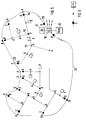
- the solid lines represent optical waveguides that are laid in a geographical area considered, for example, depending on local conditions and the need for communication links.
- a plurality of optical fibers meet each other at branch points, so that the optical fibers form an optical fiber network with these branch points.
- One of the essential features of the network according to the invention is that only three optical fibers are connected to one another at the branching points. (In an optical fiber network with a star structure, a much larger number of optical fibers are connected to each other at the star points, e.g. 16 or 46.) In order to distinguish the new network conceptually from the known network structures, it is referred to below as a branch network.
- the branch network therefore has free ends. This has the advantage that it can be extended or branched as desired, and another essential advantage, which will be described later.
- the points at which subscriber devices are connected to the network or can be connected are arbitrary points along the individual optical fibers of the network. Wherever there is a need to connect a subscriber along an optical fiber link of the network and where the optical fiber is locally accessible, a connection point can be inserted into the optical fiber. How such a connection point is made will be explained later. The same also applies if there is a need to further branch the network at any point in the course of an optical waveguide. Even then, a branch point is inserted at such a point.
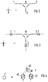
- FIG. 1 shows that there are differently symbolized branch points A and B in the branch network.
- the execution of a branch point A is shown in Fig.2.
- a branch point A is shown in Fig.2.
- it contains an optical waveguide coupler, which is produced by melting together two optical waveguide pieces according to the known technique of manufacturing fiber-fusion couplers.
- the couplers are connected so that there is an optical fiber connection between every two of three connections. They thus form a total of a coupler with three transmission paths, a first between the connections 1 and 2, a second between the connections 1 and 3 and a third between the connections 3 and 2.
- this coupler Since the light transmission in couplers and optical fibers is always bidirectional, this coupler is also bidirectional in each of the three transmission paths.
- Such a coupler is known from DE-A1-27 28 686, Fig.4. However, it is used there in a ring-shaped network.
- a branching point A realized by a coupler according to FIG. 2 is purely passive.
- branch points in the new branch network according to FIG. 1. They are designated B and implemented as shown in Fig.3. They differ from the branching points A only in that optical amplifiers C, preferably fiber-optic amplifiers with erbium-doped amplifying fibers, are inserted into the transmission paths at the connections of the coupler. Since optical amplifiers are bidirectional, the symbol of a bidirectional amplifier is used for them in FIG. It may not be necessary to provide optical amplifiers at all three connections of the coupler forming the branch point.
- Branch points of the type described above are also used to connect subscriber devices to the new network according to FIG. 1, as a rule passive branch points A. As already mentioned above, they can be inserted or inserted at any points on the individual optical fibers of the network. A so-called optical network termination F is connected to each of them via an optical waveguide piece. 4 shows how the optical network termination F can be implemented.
- optical waveguide piece 43 leading to said connection point by means of an optical waveguide coupler 40.
- a fiber-optic amplifier C is inserted into the optical waveguide piece 43 and, under certain circumstances, can also be omitted.
- terminals of the Participant can be connected directly, or multiplexers and demultiplexers can be connected to connect different end devices or different participants.
- the optical network shown in FIG. 1 has the property that optical signals which are sent into the network from a network termination F can be received by any other network termination F.
- Which optical network terminations are connected to which others is, as is known from the publication mentioned at the outset, determined by the wavelength to which the optical transmitters and the optical receivers are set.
- the optical transmitter and optical receiver are each controllable so that they send or receive at a certain wavelength.
- An wavelength-adjustable optical transmitter is e.g. from Electronics Letters, November 21, 1991, vol. 27, no. 24, pages 2268-2269 known "Y laser".
- a superimposed receiver can be used as a wavelength controllable optical receiver, e.g. is known from EP-A2 0 485 812.
- the known multiplex transmission methods can also be used for the access of the subscribers to the network, e.g. TDMA, CDMA, ATM, STM.
- Optical switching nodes are known per se (e.g. from DE-OS 41 08 213) and therefore do not require any further explanation here.
- Networks with which the optical switching node 10 can connect the branch network shown in FIG. 1 can be branch networks of the same type or it can also be a connection to a transport network that transitions to others Branch networks enabled, but contains no network terminations for participants, but otherwise how the network shown in Fig.1 can be constructed.
- An “intelligent network” 11 can also be connected to the switching node 10, by means of which any value-added services can be offered to the subscribers via the branch network, as in today's networks.
- a network management network 12 controls and monitors in the new branch network the transmission methods used, the bit rates, the message traffic, the charging and the functionality. It has access to the branch network via the optical switching node 10.
- Network management networks for controlling transmission and switching networks are known, e.g. from telcom report 14 (1991), volume 1, pages 48 - 51.
- a possible operating mode of the branch network is explained below using an example. From the foregoing, however, it is apparent that a variety of other modes of operation are possible with the new branch network.
- a number is connected to a number of optical network terminations F, which has a multimedia terminal for text, graphics, fax, video still images and audio-visual communications. If such a group of subscribers wishes to have their own network ("corporate network"), the switching node 10 uses the network management network 12 to assign this group a wavelength that is suitable for message transmission with the requested maximum bit rate.
- All optical The transmitter 41 and optical receiver 42 of the optical network terminations F of the subscriber group are now set to the wavelength and predetermined bit repetition frequency, as with an Ethernet, the network management network 12 now sends a polling signal (token) from subscriber to subscriber may now send its message to the network, for example in the form of ATM cells
- a polling signal token
- the branching structure of the network and the couplers A or B, each bidirectional in three transmission paths, are transported in each branch of the network and reach the end of each branch of the network in order to be absorbed there without reflection.
- the optical receiver of each optical network termination belonging to the group of subscribers receives the transported optical signal (the network terminations not belonging to the group cannot receive it because they are set to a different wavelength.) And uses a cell (message ) belonging address (header) whether the cell is intended for it. If the cell is to be sent to n participants, it is either sent out n times with each destination address or the participants in the group ('' conference participants '') agree on a common conference address before their conference, so that all participants have the cells (conference cells) During a conference, a participant can also hold a side meeting with one of the conference participants or with a partner not participating in the conference on the network by using the address of this conference participant or partner. The participants can use any medium of the multimedia terminal for communication.
- a virtual network for the subscriber group under consideration within the entire branch network there is, so to speak, a virtual network for the subscriber group under consideration within the entire branch network.
- the rest of the branch network can be used in parallel in any way.
- the transition from a virtual network to other virtual networks in the branching network takes place via the switching node 10 or by switching over network terminations F, controlled by the management network 12.
- the new network offers very high flexibility in every respect and manages with a minimum of different network elements.
- Another advantage of the network is that it is very simple can be expanded in terms of number of participants and geographical expansion as well as topological structure without prior investments being necessary.
- the ends of the optical waveguides forming the branching network are connected to an annular optical waveguide 50 with the aid of branching points A or B of the type already explained.
- a controllable optical switch D is inserted into the respective optical fiber.
- the end of an optical fiber of the branching network is therefore only connected to the ring line 50 when the optical switch D in question is "closed". If part of the branch network fails, e.g.
- the free ends of the optical waveguides of the branch network are terminated without reflection.
- the optical switch D and a branch point at their end as shown in FIG. 5, this is provided by the optical switch being designed to be reflection-free.
- Optical switches are known per se and are usually reflection-free.
- a suitable optical switch is e.g. the aforementioned Y laser, which can also be operated as an optical switch.
- Fig. 6 shows that the element D shown in Fig. 5 has the function of an (optical) switch.
- the thick side of the optical switch is intended to symbolize its freedom from reflection.
Landscapes
- Engineering & Computer Science (AREA)
- Computer Networks & Wireless Communication (AREA)
- Physics & Mathematics (AREA)
- Electromagnetism (AREA)
- Signal Processing (AREA)
- Optical Communication System (AREA)
- Small-Scale Networks (AREA)
Abstract
Description
Die Erfindung betrifft ein Netz zur Übermittlung von Nachrichten zwischen an Anschlußpunkten des Netzes angeschlossenen Teilnehmern durch Licht als Träger, bei dem von jedem der Teilnehmer in das Netz gesendete optische Signale an jedem Teilnehmer-Anschlußpunkt empfangen werden können.The invention relates to a network for transmitting messages between subscribers connected to connection points of the network by light as a carrier, in which optical signals sent by each of the subscribers into the network can be received at each subscriber connection point.
Ein Netz mit den vorstehend genannten Merkmalen ist bekannt aus M. Brain und P. Cochrane: "Eradicating the central office with Coherent Optical Technology", 1988 International Zürich Seminar on Digital Communications: Mapping New Application onto New Technologies (Cat. No. 88 TH 0202-2), Seiten 59 bis 62.A network with the features mentioned above is known from M. Brain and P. Cochrane: "Eradicating the central office with Coherent Optical Technology", 1988 International Zurich Seminar on Digital Communications: Mapping New Application onto New Technologies (Cat. No. 88 TH 0202-2), pages 59 to 62.
Zur Übertragungskapazität des Netzes haben alle angeschlossenen Teilnehmer Zugriff. Das Netz wird auch als "Optischer Äther" bezeichnet. Nachrichtenverbindungen können durch Wahl der Wellenlängen der bei den Teilnehmern vorhandenen optischen Sender und Empfänger eingerichtet werden. Dadurch hat das Netz eine hohe Flexibilität.All connected participants have access to the transmission capacity of the network. The network is also referred to as "optical ether". Communication links can be set up by selecting the wavelengths of the optical transmitters and receivers available to the participants. This gives the network a high degree of flexibility.
Die Topologie des Netzes ist entweder sternförmig oder ringförmig. Bei der sternförmigen Topologie befinden sich die Teilnehmer-Anschlußpunkte an den Enden der sternförmig verlaufenden Lichtwellenleiter. An den Sternpunkten des Netzes befinden sich passive Leistungsteiler, in der Literatur üblicherweise Sternkoppler genannt, an denen eine große Anzahl von Lichtwellenleitern miteinander verbunden sind. Dadurch entstehen vielerlei Reflexionen von optischen Signalen bei Ihrer Ausbreitung über das Netz, so daß bei den Teilnehmern ein großer technischer Aufwand getrieben werden muß, um unerwünschte und störende Informationen zu unterdrücken. Ein weiterer Nachteil ist, daß die Betriebssicherheit und Qualität der Nachrichtenübertragung in dem Netz sehr stark von der Qualität der wenigen Sternkoppler abhängt. Ein einziger nicht oder schlecht funktionierender Sternkoppler schadet also der Qualität einer Vielzahl von Nachrichtenverbindungen. Im übrigen haben Sternkoppler generell den Nachteil, daß sie optische Signale stark dämpfen.The topology of the network is either star-shaped or ring-shaped. With the star-shaped topology, the subscriber connection points are located at the ends of the star-shaped optical fibers. At the star points of the network there are passive power dividers, usually called star couplers in the literature, at which a large number of optical fibers are connected to one another. This causes many reflections of optical signals as they propagate over the network, so that the participants have to make a great technical effort to suppress unwanted and disruptive information. Another disadvantage is that the operational reliability and quality of message transmission in the network depend very much on the quality of the few star couplers. A single star coupler that is not functioning or is malfunctioning thus damages the quality of a large number of communication links. In addition, star couplers generally have the disadvantage that they strongly attenuate optical signals.
Es ist die Aufgabe der Erfindung, ein optisches Netz anzugeben, das mit dem bekannten Netz zwar die eingangs genannten Merkmale gemeinsam hat, jedoch die geschilderten Nachteile nicht mehr aufweist.It is the object of the invention to provide an optical network which, although having the features mentioned at the outset, does not have the disadvantages described.
Die Aufgabe ist wie im Patentanspruch angegeben gelöst. Weiterbildungen ergeben sich aus den Unteransprüchen.The object is achieved as indicated in the claim. Further training results from the subclaims.
Die Erfindung wird nun anhand der Zeichnungen, die Ausführungsbeispiele zeigen, näher erläutert.The invention will now be explained in more detail with reference to the drawings, which show exemplary embodiments.
Es zeigen:
Figur 1- ein Beispiel des neuen Verzweigungsnetzes mit Verzweigungspunkten und Anschlußpunkten für Teilnehmer,
Figur 2- ein Ausführungsbeispiel der in Fig.1 gezeigten Verzweigungspunkte A,
- Figur 3
- ein Ausführungsbeispiel der in Fig.1 gezeigten Verzweigungspunkte B,
- Figur 4
- ein Ausführungsbeispiel der in Fig.1 gezeigten optischen Netzabschlüsse F,
- Figur 5
- das in Fig.1 gezeigte erfindungsgemäße Netz, erweitert durch eine Ringleitung und
- Figur 6
- eine schematische Darstellung der Funktion des in Fig.5 mit D bezeichneten Symbols.
- Figure 1
- an example of the new branch network with branch points and connection points for participants,
- Figure 2
- 1 shows an exemplary embodiment of the branching points A shown in FIG. 1,
- Figure 3
- 1 shows an exemplary embodiment of the branching points B shown in FIG. 1,
- Figure 4
- 1 shows an exemplary embodiment of the optical network terminations F shown in FIG. 1,
- Figure 5
- the network shown in Figure 1, expanded by a ring line and
- Figure 6
- is a schematic representation of the function of the symbol labeled D in FIG.
In Fig.1 stellen die durchgezogenen Linien Lichtwellenleiter dar, die in einem beispielsweise betrachteten geographischen Gebiet je nach örtlichen Gegebenheiten und Bedarf an Nachrichtenübertragungsstrecken verlegt sind. An Verzweigungspunkten stoßen jeweils mehrere Lichtwellenleiter aufeinander, so daß die Lichtwellenleiter mit diesen Verzweigungspunkten ein Lichtwellenleiter-Netz bilden. Eines der wesentlichen Merkmale des erfindungsgemäßen Netzes ist, daß an den Verzweigungspunkten nur drei Lichtwellenleiter miteinander verbunden sind. (Bei einem Lichtwellenleiter-Netz mit Sternstruktur sind an den Sternpunkten eine weit größere Anzahl von Lichtwellenleitern miteinander verbunden, z.B. 16 oder 46.) Um das neue Netz begrifflich von den bekannten Netzstrukturen zu unterscheiden, wird es im folgenden als Verzweigungsnetz bezeichnet.In FIG. 1, the solid lines represent optical waveguides that are laid in a geographical area considered, for example, depending on local conditions and the need for communication links. A plurality of optical fibers meet each other at branch points, so that the optical fibers form an optical fiber network with these branch points. One of the essential features of the network according to the invention is that only three optical fibers are connected to one another at the branching points. (In an optical fiber network with a star structure, a much larger number of optical fibers are connected to each other at the star points, e.g. 16 or 46.) In order to distinguish the new network conceptually from the known network structures, it is referred to below as a branch network.
Ein weiteres wesentliches Merkmal ist, daß an Enden von Lichtwellenleitern keine Teilnehmereinrichtungen angeschlossen sind. Das Verzweigungsnetz hat also freie Enden. Dies hat den Vorteil, daß es beliebig verlängerbar oder weiter verzweigbar ist und noch einen wesentlichen Vorteil, der an späterer Stelle beschrieben wird.Another essential feature is that no subscriber devices are connected to the ends of optical fibers. The branch network therefore has free ends. This has the advantage that it can be extended or branched as desired, and another essential advantage, which will be described later.
Um sicherzustellen, daß an freien Enden von Lichtwellenleitern keine störenden Reflexionen von optischen Signalen auftreten, sind diese Enden reflexionsfrei abgeschlossen. Dies ist eine an sich bekannte Technik, die z.B. in dem Buch " Optische Informationsübertragung mit Lichtwellenleitern" von D. Rosenberger, Expertverlag, 7031 Grafenau 1/Württ, 1982, auf Seite 138 im Abschnitt 8.4.4, für offene optische T-Busse erwähnt ist. Sie bedarf daher hier keiner näheren Erläuterung.In order to ensure that no disturbing reflections from optical signals occur at free ends of optical waveguides, these ends are terminated without reflection. This is one in itself Known technology, which is mentioned for example in the book "Optical Information Transmission with Optical Waveguides" by D. Rosenberger, Expertverlag, 7031 Grafenau 1 / Württ, 1982, on page 138 in section 8.4.4, for open optical T-buses. It therefore requires no further explanation here.
Ein weiteres Merkmal des erfindungsgemäßen Verzweigungsnetzes ist, daß die Punkte, an denen Teilnehmereinrichtungen an das Netz angeschlossen sind oder anschließbar sind, beliebige Punkte entlang der einzelnen Lichtwellenleiter des Netzes sind. Wo immer entlang einer Lichtwellenleiterstrecke des Netzes Bedarf ist, einen Teilnehmer anzuschließen und wo der Lichtwellenleiter örtlich zugänglich ist, kann ein Anschlußpunkt in den Lichtwellenleiter eingefügt werden. Wie ein solcher Anschlußpunkt beschaffen ist, wird an späterer Stelle erläutert. Das entsprechende gilt auch, wenn Bedarf entsteht, das Netz an irgendeiner Stelle innerhalb des Verlaufes eines Lichtwellenleiters weiter zu verzweigen. Auch dann wird an einer solchen Stelle ein Verzweigungspunkt eingefügt.Another feature of the branching network according to the invention is that the points at which subscriber devices are connected to the network or can be connected are arbitrary points along the individual optical fibers of the network. Wherever there is a need to connect a subscriber along an optical fiber link of the network and where the optical fiber is locally accessible, a connection point can be inserted into the optical fiber. How such a connection point is made will be explained later. The same also applies if there is a need to further branch the network at any point in the course of an optical waveguide. Even then, a branch point is inserted at such a point.
Wie Verzweigungspunkte erfindungsgemäß beschaffen sind, wird nachstehend erläutert. Die Fig.1 zeigt, daß es in dem Verzweigungsnetz unterschiedlich symbolisierte Verzweigungspunkte A und B gibt. Die Ausführung eines Verzweigungspunktes A ist in Fig.2 gezeigt. Für die drei durch ihn zu verbindenden Lichtwellenleiter hat er drei Anschlüsse 1, 2 und 3. An jedem Anschluß enthält er einen Lichtwellenleiter-Koppler, der durch Aneinanderschmelzen zweier Lichtwellenleiterstücke nach der an sich bekannten Technik der Herstellung von Faser-Schmelzkopplern hergestellt ist. Die Koppler sind dabei so verbunden, daß zwischen jeweils zwei von drei Anschlüssen eine Lichtwellenleiter-Verbindung besteht. Sie bilden somit insgesamt einen Koppler mit drei Übertragungswegen, einen ersten zwischen den Anschlüssen 1 und 2, einen zweiten zwischen den Anschlüssen 1 und 3 und einen dritten zwischen den Anschlüssen 3 und 2. Da die Lichtübertragung in Kopplern und Lichtwellenleitern immer bidirektional ist, ist auch dieser Koppler in den drei Übertragungswegen jeweils bidirektional. Ein derartiger Koppler ist bekannt aus der DE-A1-27 28 686, Fig.4. Verwendet ist er dort allerdings in einem ringförmigen Netz.How branching points are created according to the invention is explained below. 1 shows that there are differently symbolized branch points A and B in the branch network. The execution of a branch point A is shown in Fig.2. For the three optical waveguides to be connected by it, it has three
Wie man sieht, ist ein durch einen Koppler nach Fig.2 realisierter Verzweigungspunkt A rein passiv. Im Gegensatz dazu gibt es im neuen Verzweigungsnetz nach Fig.1 auch aktive Verzweigungspunkte. Sie sind mit B bezeichnet und wie in Fig.3 gezeigt realisiert. Von den Verzweigungspunkten A unterscheiden sie sich nur dadurch, daß an den Anschlüssen des Kopplers optische Verstärker C, vorzugsweise faseroptische Verstärker mit Erbium-dotierten Verstärkungsfasern, in die Übertragungswege eingefügt sind. Da optische Verstärker bidirektional sind, ist für sie in der Fig.3 das Symbol eines bidirektionalen Verstärkers verwendet. Unter Umständen ist es nicht erforderlich, an allen drei Anschlüssen des den Verzweigungspunkt bildenden Kopplers optische Verstärker vorzusehen.As can be seen, a branching point A realized by a coupler according to FIG. 2 is purely passive. In contrast, there are also active branch points in the new branch network according to FIG. 1. They are designated B and implemented as shown in Fig.3. They differ from the branching points A only in that optical amplifiers C, preferably fiber-optic amplifiers with erbium-doped amplifying fibers, are inserted into the transmission paths at the connections of the coupler. Since optical amplifiers are bidirectional, the symbol of a bidirectional amplifier is used for them in FIG. It may not be necessary to provide optical amplifiers at all three connections of the coupler forming the branch point.
Zum Anschluß von Teilnehmereinrichtungen an das neue Netz nach Fig.1 dienen ebenfalls Verzweigungspunkte der vorstehend beschriebenen Art, im Regelfalle passive Verzweigungspunkte A. Wie bereits oben erwähnt, können sie an beliebigen Punkten der einzelnen Lichtwellenleiter des Netzes eingefügt sein oder eingefügt werden. An sie ist jeweils ein sogenannter optischer Netzabschluß F über ein Lichtwellenleiterstück angeschlossen. Fig.4 zeigt, wie der optische Netzabschluß F realisiert sein kann.Branch points of the type described above are also used to connect subscriber devices to the new network according to FIG. 1, as a rule passive branch points A. As already mentioned above, they can be inserted or inserted at any points on the individual optical fibers of the network. A so-called optical network termination F is connected to each of them via an optical waveguide piece. 4 shows how the optical network termination F can be implemented.
Mittels eines Lichtwellenleiter-Kopplers 40 ist der Ausgang eines optischen Senders 41 und der Eingang eines optischen Empfängers 42 an ein zu dem genannten Anschlußpunkt führendes Lichtwellenleiter-Stück 43 angeschlossen. In das Lichtwellenleiter-Stück 43 ist ein faseroptischer Verstärker C eingefügt, der, unter Umständen, auch entfallen kann. An diesem optischen Netzanschluß F können Endgeräte des Teilnehmers direkt angeschlossen werden, oder es können Multiplexer und Demultiplexer zum Anschluß verschiedener Endgeräte oder verschiedener Teilnehmer angeschlossen werden.The output of an optical transmitter 41 and the input of an optical receiver 42 are connected to an
Wie ohne weiteres ersichtlich ist, hat das in Fig.1 gezeigte optische Netz die Eigenschaft, daß optische Signale, die von einem Netzabschluß F aus in das Netz gesendet werden, von jedem anderen Netzabschluß F empfangen werden können. Welche optischen Netzabschlüsse mit welchen anderen in Verbindung stehen, wird, wie aus der eingangs genannten Veröffentlichung bekannt, durch die Wellenlänge bestimmt, auf die die optischen Sender und die optischen Empfänger eingestellt sind. Die optischen Sender und optischen Empfänger sind also jeweils so steuerbar, daß sie bei einer bestimmten Wellenlänge senden bzw. empfangen.As can be readily seen, the optical network shown in FIG. 1 has the property that optical signals which are sent into the network from a network termination F can be received by any other network termination F. Which optical network terminations are connected to which others is, as is known from the publication mentioned at the outset, determined by the wavelength to which the optical transmitters and the optical receivers are set. The optical transmitter and optical receiver are each controllable so that they send or receive at a certain wavelength.
Ein in der Wellenlänge einstellbarer optischer Sender ist z.B. der aus Electronics Letters, 21. November 1991, Vol. 27, No. 24, Seiten 2268-2269 bekannte "Y-Laser". Als ein in der Wellenlänge steuerbarer optischer Empfänger kann ein Überlagerungsempfänger verwendet werden, wie er z.B. aus der EP-A2 0 485 812 bekannt ist. Für den Zugriff der Teilnehmer zu dem Netz können auch die bekannten Multiplex-Übertragungsverfahren angewendet werden, z.B. TDMA, CDMA, ATM, STM.An wavelength-adjustable optical transmitter is e.g. from Electronics Letters, November 21, 1991, vol. 27, no. 24, pages 2268-2269 known "Y laser". A superimposed receiver can be used as a wavelength controllable optical receiver, e.g. is known from EP-A2 0 485 812. The known multiplex transmission methods can also be used for the access of the subscribers to the network, e.g. TDMA, CDMA, ATM, STM.
Ein optischer Vermittlungsknoten 10 (in Fig.1 mit den Buchstaben SC bezeichnet, SC = Switching Center) dient dazu, das optische Netz mit einem oder mehreren anderen optischen Netzen zu verbinden. Optische Vermittlungsknoten sind an sich bekannt (z.B. aus DE-OS 41 08 213) und bedürfen daher hier keiner näheren Erläuterung.An optical switching node 10 (designated by the letters SC in FIG. 1, SC = switching center) serves to connect the optical network to one or more other optical networks. Optical switching nodes are known per se (e.g. from DE-OS 41 08 213) and therefore do not require any further explanation here.
Netze, mit denen der optische Vermittlungsknoten 10 das in Fig.1 gezeigte Verzweigungsnetz verbinden kann, können Verzweigungsnetze gleicher Art sein oder es kann auch eine Verbindung zu einem Transportnetz realisiert sein, das Übergänge in andere Verzweigungsnetze ermöglicht, aber keine Netzabschlüsse für Teilnehmer enthält, jedoch ansonsten wie das in Fig.1 gezeigte Netz aufgebaut sein kann. An den Vermittlungsknoten 10 kann auch ein "Intelligentes Netz" 11 angeschlossen sein, durch das wie in heutigen Netzen beliebige Mehrwertdienste den Teilnehmern über das Verzweigungsnetz angeboten werden können.Networks with which the
Ein Netzwerk-Management-Netz 12 steuert und überwacht in dem neuen Verzweigungsnetz die angewendeten Übertragungsverfahren, die Bitraten, den Nachrichtenverkehr, die Gebührenerfassung und die Funktionsfähigkeit. Es hat über den optischen Vermittlungsknoten 10 Zugang zu dem Verzweigungsnetz. Netzwerk-Management-Netze zur Steuerung von Übertragungs- und Vermittlungsnetzen sind bekannt, z.B. aus telcom report 14 (1991), Heft 1, Seiten 48 - 51.A
Nachstehend wird eine mögliche Betriebsform des Verzweigungsnetzes an einem Beispiel erläutert. Aus dem vorstehenden ist jedoch offensichtlich, daß eine Vielzahl anderer Betriebsformen mit dem neuen Verzweigungsnetz möglich sind. An einer Anzahl von optischen Netzabschlüssen F sei je ein Teilnehmer angeschlossen, der ein Multimedial-Terminal für Text-, Graphik-, Fax-, Videofestbild und Audio-visuelle-Kommunikationen besitzt. Falls eine solche Teilnehmergruppe ein eigenes Netz ("Corporate Network'') wünscht, so teilt der Vermittlungsknoten 10 dieser Gruppe mit Hilfe des Netzwerk-Management-Netzes 12 eine Wellenlänge zu, die für eine Nachrichtenübertragung mit der angeforderten maximalen Bitfolgefrequenz geeignet ist. Alle optischen Sender 41 und optischen Empfänger 42 der optischen Netzabschlüsse F der Teilnehmergruppe werden nun auf die Wellenlänge und vorgegebene Bitfolgefrequenz eingestellt. Das Netzwerk-Management-Netz 12 sendet nun wie bei einem Ethernet von Teilnehmer zu Teilnehmer ein Abrufsignal (Token). Der dadurch angesprochene Netzabschluß F darf nun seine Nachricht in das Netz absenden, z.B. in Form von ATM-Zellen. Jede gesendete Zelle wird aufgrund der Verzweigungsstruktur des Netzes und der in drei Übertragungswegen jeweils bidirektionalen Koppler A oder B in jedem Zweig des Netzes transportiert und gelangt bis an das Ende jedes Zweigs des Netzes, um dort reflexionsfrei absorbiert zu werden. Der optische Empfänger jedes optischen Netzabschlusses, der der Gruppe von Teilnehmern angehört, empfängt das transportierte optische Signal (Die der Gruppe nicht angehörenden Netzabschlüsse können es nicht empfangen, weil sie auf eine andere Wellenlänge eingestellt sind.) und erkennt mit Hilfe einer zur Zelle (Nachricht) gehörenden Adresse (Header), ob die Zelle für ihn bestimmt ist. Soll die Zelle an n Teilnehmern gesendet werden, so wird sie entweder n mal mit jeder Zieladresse ausgesendet oder die der Gruppe angehörenden Teilnehmer (''Konferenzteilnehmer") vereinbaren vor ihrer Konferenz eine gemeinsame Konferenzadresse, so daß alle Teilnehmer die Zellen (Konferenz-Zellen) erhalten. Ein Teilnehmer kann während einer Konferenz auch ein ''Side-Meeting" mit einem der Konferenzteilnehmer oder mit einem nicht an der Konferenz teilnehmenden Partner im Netz abhalten, indem er die Adresse dieses Konferenzteilnehmers oder Partners benutzt. Die Teilnehmer können jedes beliebige Medium des Multimedia-Terminals zur Kommunikation benutzen.A possible operating mode of the branch network is explained below using an example. From the foregoing, however, it is apparent that a variety of other modes of operation are possible with the new branch network. A number is connected to a number of optical network terminations F, which has a multimedia terminal for text, graphics, fax, video still images and audio-visual communications. If such a group of subscribers wishes to have their own network ("corporate network"), the switching
Bei der oben geschilderten Betriebsart besteht für die betrachtete Teilnehmergruppe sozusagen ein virtuelles Netz innerhalb des gesamten Verzweigungsnetzes. Der restliche Teil des Verzweigungsnetzes kann parallel dazu in beliebiger Weise benutzt werden. Der Übergang von einem virtuellen Netz in andere virtuelle Netze des Verzweigungsnetzes geschieht über den Vermittlungsknoten 10 oder durch Umschaltung von Netzabschlüssen F, gesteuert durch das Management-Netz 12.In the operating mode described above, there is, so to speak, a virtual network for the subscriber group under consideration within the entire branch network. The rest of the branch network can be used in parallel in any way. The transition from a virtual network to other virtual networks in the branching network takes place via the switching
Wie aus der vorstehenden Beschreibung ersichtlich ist, bietet das neue Netz in jeder Hinsicht eine sehr hohe Flexibilität und kommt mit einem Minimum von verschiedenartigen Netzelementen aus. Ein weiterer Vorteil des Netzes ist, daß es auf einfachste Weise hinsichtlich Teilnehmerzahl und geographischer Ausdehnung sowie topologischer Struktur erweiterbar ist, ohne daß Vorinvestitionen erforderlich sind.As can be seen from the above description, the new network offers very high flexibility in every respect and manages with a minimum of different network elements. Another advantage of the network is that it is very simple can be expanded in terms of number of participants and geographical expansion as well as topological structure without prior investments being necessary.
Was die Betriebssicherheit des Netzes betrifft, so bietet es noch einen besonderen Vorteil, der anhand von Fig.5 erläutert wird. Gemäß einer Weiterbildung der Erfindung sind die Enden der das Verzweigungsnetz bildenden Lichtwellenleiter mit Hilfe von Verzweigungspunkten A oder B der bereits erläuterten Art an einen ringförmig verlaufenden Lichtwellenleiter 50 angeschlossen. Am Ende jedes der Lichtwellenleiter des Verzweigungsnetzes vor dem Verzweigungspunkt A oder B ist in den jeweiligen Lichtwellenleiter ein steuerbarer optischer Schalter D eingefügt. Das Ende eines Lichtwellenleiters des Verzweigungsnetzes ist also nur dann an die Ringleitung 50 angeschlossen, wenn der betreffende optische Schalter D "geschlossen" ist. Fällt ein Teil des Verzweigungsnetzes aus, z.B. durch Faserbruch oder durch Ausfall eines der Verzweigungspunkte, so kann dies mit Hilfe der optischen Ringleitung und der optischen Schalter D leicht behoben werden. Bricht z.B. der zwischen Verzweigungspunkten 51 und 52 verlaufende Lichtwellenleiter, wie es in Fig.5 an einer Stelle E angedeutet ist, so kann der dadurch verursachte teilweise Ausfall des Verzweigungsnetzes ersetzt werden, indem man die optischen Schalter 53, 54 und 55 schließt. Die in Fig.5 gezeigte erfindungsgemäße Kombination des Verzweigungsnetzes mit der optischen Ringleitung bietet höchste Betriebssicherheit und hohen Schutz der Verfügbarkeit der Nachrichtenverbindung, z.B. auch gegenüber Gewaltakten (Terrorismus).As far as the operational security of the network is concerned, it offers a particular advantage, which is explained with reference to FIG. 5. According to a development of the invention, the ends of the optical waveguides forming the branching network are connected to an annular
Wie oben erwähnt, sind die freien Enden der Lichtwellenleiter des Verzweigungsnetzes reflexionsfrei abgeschlossen. Im Falle, daß sie wie in Fig.5 gezeigt jeweils einen optischen Schalter D und einen Verzweigungspunkt an ihrem Ende haben, ist dies gegeben, indem der optische Schalter reflexionsfrei ausgeführt ist.As mentioned above, the free ends of the optical waveguides of the branch network are terminated without reflection. In the event that they each have an optical switch D and a branch point at their end, as shown in FIG. 5, this is provided by the optical switch being designed to be reflection-free.
Optische Schalter sind an sich bekannt, und sie sind normalerweise reflexionsfrei. Ein geeigneter optischer Schalter ist z.B. der oben erwähnte bekannte Y-Laser, der auch als optischer Schalter betreibbar ist.Optical switches are known per se and are usually reflection-free. A suitable optical switch is e.g. the aforementioned Y laser, which can also be operated as an optical switch.
Fig.6 zeigt, daß das in Fig.5 dargestellte Element D die Funktion eines (optischen) Schalters hat. Die dick gezeichnete Seite des optischen Schalters soll seine Reflexionsfreiheit symbolisieren.Fig. 6 shows that the element D shown in Fig. 5 has the function of an (optical) switch. The thick side of the optical switch is intended to symbolize its freedom from reflection.
Claims (5)
dadurch gekennzeichnet,
characterized by
dadurch gekennzeichnet, daß eine Lichtwellenleiter-Ringleitung (50) vorhanden ist, daß an den Enden der Lichtwellenleiter des Netzes steuerbare optische Schalter (D) vorhanden sind, über die die Enden mit der Lichtwellenleiter-Ringleitung verbunden werden können.Network according to claim 1,
characterized in that an optical waveguide ring line (50) is provided, that controllable optical switches (D) are provided at the ends of the optical waveguides of the network, via which the ends can be connected to the optical waveguide ring line.
dadurch gekennzeichnet, daß ein Netzwerk-Management-Netz (12) vorhanden ist, um das Netz zu steuern und zu überwachen.Network according to claim 1 or 2,
characterized in that a network management network (12) is provided to control and monitor the network.
dadurch gekennzeichnet, daß ein optischer Vermittlungsknoten (10) vorhanden ist, der das Netz mit gleichartigen Netzen verbindet.Network according to one of claims 1 to 3,
characterized in that there is an optical switching node (10) which connects the network to similar networks.
dadurch gekennzeichnet, daß Verzweigungspunkte (A, B) an beliebigen Stellen des Netzes einfügbar sind.Network according to claim 1,
characterized in that branch points (A, B) can be inserted anywhere in the network.
Applications Claiming Priority (2)
| Application Number | Priority Date | Filing Date | Title |
|---|---|---|---|
| DE4318732A DE4318732A1 (en) | 1993-06-05 | 1993-06-05 | Optical network |
| DE4318732 | 1993-06-05 |
Publications (2)
| Publication Number | Publication Date |
|---|---|
| EP0629099A2 true EP0629099A2 (en) | 1994-12-14 |
| EP0629099A3 EP0629099A3 (en) | 1995-08-02 |
Family
ID=6489711
Family Applications (1)
| Application Number | Title | Priority Date | Filing Date |
|---|---|---|---|
| EP94108049A Withdrawn EP0629099A3 (en) | 1993-06-05 | 1994-05-25 | Optical network. |
Country Status (7)
| Country | Link |
|---|---|
| US (1) | US5502586A (en) |
| EP (1) | EP0629099A3 (en) |
| JP (1) | JPH07143071A (en) |
| AU (1) | AU676029B2 (en) |
| CA (1) | CA2124900A1 (en) |
| DE (1) | DE4318732A1 (en) |
| NZ (1) | NZ260626A (en) |
Cited By (2)
| Publication number | Priority date | Publication date | Assignee | Title |
|---|---|---|---|---|
| WO1997013291A1 (en) * | 1995-10-05 | 1997-04-10 | Robert Bosch Gmbh | Redundant optical waveguide network |
| DE102012014506A1 (en) * | 2012-07-20 | 2014-01-23 | Ulrich Lohmann | Optical cross connection structure for fiber-optic data communication network, performs uniform division ratio distribution of linked light power at input end to realize three outputs, and realizes division ratio unification of power |
Families Citing this family (8)
| Publication number | Priority date | Publication date | Assignee | Title |
|---|---|---|---|---|
| DE19625806A1 (en) * | 1996-06-27 | 1998-01-02 | Bosch Gmbh Robert | Terminal for an optical network, optical network and central office therefor |
| DE19640690C2 (en) * | 1996-10-02 | 1999-07-08 | Werner Wolfrum | Method for transmitting digital information or data, and a network termination and an optical fiber network therefor |
| DE69913488T2 (en) * | 1998-01-03 | 2004-10-28 | British Telecommunications Public Limited Company | Communication system with star / ring topology |
| US6151336A (en) * | 1998-02-11 | 2000-11-21 | Sorrento Networks, Inc. | Time division multiplexing expansion subsystem |
| US6400478B1 (en) | 1998-04-02 | 2002-06-04 | Sorrento Networks, Inc. | Wavelength-division-multiplexed optical transmission system with expanded bidirectional transmission capacity over a single fiber |
| US6298103B1 (en) | 1998-06-16 | 2001-10-02 | Sorrento Networks Corporation | Flexible clock and data recovery module for a DWDM optical communication system with multiple clock rates |
| US6885677B1 (en) | 1999-03-12 | 2005-04-26 | Fujitsu Limited | Multiprotocol label switching routers |
| US7123836B2 (en) * | 2001-07-16 | 2006-10-17 | Avago Technologies Fiber Ip (Singapore) Pte. Ltd. | All-optical network distribution system |
Citations (1)
| Publication number | Priority date | Publication date | Assignee | Title |
|---|---|---|---|---|
| DE2728686A1 (en) * | 1976-06-29 | 1978-01-12 | Int Standard Electric Corp | OPTICAL DATA TRANSFER SYSTEM |
Family Cites Families (5)
| Publication number | Priority date | Publication date | Assignee | Title |
|---|---|---|---|---|
| US4704713A (en) * | 1985-12-26 | 1987-11-03 | Bell Communications Research, Inc. | Optical ring network |
| US4901306A (en) * | 1987-02-24 | 1990-02-13 | American Telephone And Telegraph Company, At&T Bell Laboratories | Wavelength-division multiplexed optical fiber network |
| DE59105787D1 (en) * | 1990-11-15 | 1995-07-27 | Sel Alcatel Ag | Device for the optical overlay reception of signals. |
| GB2251957B (en) * | 1990-11-29 | 1993-12-15 | Toshiba Kk | Optical coupler |
| DE4108213A1 (en) * | 1991-03-14 | 1992-09-17 | Standard Elektrik Lorenz Ag | OPTICAL INTERFACE AND SWITCHING MODULE DAFUER |
-
1993
- 1993-06-05 DE DE4318732A patent/DE4318732A1/en not_active Withdrawn
-
1994
- 1994-05-25 EP EP94108049A patent/EP0629099A3/en not_active Withdrawn
- 1994-05-26 AU AU63383/94A patent/AU676029B2/en not_active Ceased
- 1994-05-31 NZ NZ260626A patent/NZ260626A/en unknown
- 1994-06-01 CA CA002124900A patent/CA2124900A1/en not_active Abandoned
- 1994-06-02 JP JP6121502A patent/JPH07143071A/en active Pending
- 1994-06-03 US US08/253,769 patent/US5502586A/en not_active Expired - Fee Related
Patent Citations (1)
| Publication number | Priority date | Publication date | Assignee | Title |
|---|---|---|---|---|
| DE2728686A1 (en) * | 1976-06-29 | 1978-01-12 | Int Standard Electric Corp | OPTICAL DATA TRANSFER SYSTEM |
Non-Patent Citations (8)
| Title |
|---|
| CONFERENCE RECORD, IEEE GLOBAL TELECOMMUNICATIONS CONFERENCE, 2-5 DEZ. 1990, HEFT 1 SEITEN 65-71, SAN DIEGO US, XP 000218698 F. ELLEFSON 'Migration of Fault Tolerant Networks' * |
| CONFERENCE RECORD, IEEE INTERNATIONAL CONFERENCE ON COMMUNICATIONS, 23-26 MAI 1993, HEFT 1 SEITEN 237-244, GENF CH, XP 000371100 J.M. WILLIAMS ET AL 'The Role of the Wideband Digital Cross-connect System in Survivable Ring Networks' * |
| ELECTRONICS LETTERS, Bd. 20,Nr. 18, 30.August 1984 STEVENAGE GB, Seiten 722-723, A.P. MC DONNA ET AL '1.3 micro m. Bidirectional Optical Transmission over 31km of Installed Single-Mode Fibre Using Optical Couplers' * |
| IEEE JOURNAL ON SELECTED AREAS IN COMMUNICATIONS, Bd. SAC-4,Nr. 4, Juli 1986 NEW YORK US, Seiten 551-564, A. ALI ET AL 'Services Integration and Multiplexing for Broad-Band Communications Systems' * |
| IEEE PHOTONICS TECHNOLOGY LETTERS, Bd. 3,Nr. 3, M{rz 1991 NEW YORK US, Seiten 247-249, XP 000202941 M. IRSHID ET AL 'Distributed Optical Passive Star Couplers' * |
| JOURNAL OF LIGHTWAVE TECHNOLOGY, Bd. 6,Nr. 3, M{rz 1988 NEW YORK US, Seiten 392-398, XP 000471592 A.A.M. SALEH ET AL 'Reflective Single-Mode Fiber-Optic Passive Star Couplers' * |
| ROSENBERGER D. 'Optische Informations}bertragung mit Lichtwellenleitern' 1982 , BERLIN VDE VERLAG , BERLIN 48 * Seite 131, Zeile 3 - Seite 139, Zeile 37; Abbildungen 8.12-8.14 * * |
| TELCOM REPORT, Bd. 14,Nr. 1, Januar 1991 MUNCHEN DE, Seiten 48-51, XP 000177879 W. TROMBALLA 'Management von ]bertragungsnetzen' * |
Cited By (2)
| Publication number | Priority date | Publication date | Assignee | Title |
|---|---|---|---|---|
| WO1997013291A1 (en) * | 1995-10-05 | 1997-04-10 | Robert Bosch Gmbh | Redundant optical waveguide network |
| DE102012014506A1 (en) * | 2012-07-20 | 2014-01-23 | Ulrich Lohmann | Optical cross connection structure for fiber-optic data communication network, performs uniform division ratio distribution of linked light power at input end to realize three outputs, and realizes division ratio unification of power |
Also Published As
| Publication number | Publication date |
|---|---|
| JPH07143071A (en) | 1995-06-02 |
| US5502586A (en) | 1996-03-26 |
| EP0629099A3 (en) | 1995-08-02 |
| CA2124900A1 (en) | 1994-12-06 |
| NZ260626A (en) | 1996-11-26 |
| AU676029B2 (en) | 1997-02-27 |
| DE4318732A1 (en) | 1994-12-08 |
| AU6338394A (en) | 1994-12-08 |
Similar Documents
| Publication | Publication Date | Title |
|---|---|---|
| DE69531594T2 (en) | Communication network with a ring structure via an optical carrier and reconfigurable nodes for this structure | |
| DE60314972T2 (en) | Signaling protocol and guard ring architecture | |
| DE69433209T2 (en) | DISTRIBUTED TELECOMMUNICATION SWITCHING SYSTEM | |
| DE60023916T2 (en) | DEVICE AND METHOD FOR PACKET TRANSMISSION IN A RING NETWORK | |
| DE60127843T2 (en) | Restart on IP / Optical layer after failure of a router | |
| EP0458782B1 (en) | Star-shaped network for data communication between stations | |
| DE69731910T2 (en) | Optical network with protection arrangement | |
| WO1991009476A1 (en) | Transmission device with an optical transmission path | |
| DE69836196T2 (en) | A switching device operating according to an asynchronous transfer mode and corresponding control method | |
| EP0972367B1 (en) | Access network for transmitting optical signals | |
| EP0629099A2 (en) | Optical network | |
| DE2619391B2 (en) | Message system with multiple access and decentralized switching | |
| EP1097540B1 (en) | Method and device for optimising the transmission safety and the defect tolerance in high-bit-rate data networks | |
| EP0873035A2 (en) | Local area network with converting means | |
| DE3937738A1 (en) | SUBSCRIBER CONNECTION NODE OF A DIGITAL MESSAGE TRANSMISSION SYSTEM | |
| EP0729247A2 (en) | Method and device for optimal usage of transmission capacity in synchronous bidirectional ring networks | |
| EP1282328A1 (en) | Method of establishing telecommunications connections in the connection area of a subscriber switch, subscriber interface system, subscriber switch, and subscriber access point | |
| DE19911957C2 (en) | Remote configurable optical communication network | |
| EP0162994A1 (en) | Communication network and its application | |
| DE60223758T2 (en) | Method, apparatus and signaling in a distributed guard ring architecture | |
| EP1097605A2 (en) | Method and circuit for creating data signal links | |
| DE10343615A1 (en) | Network node for an optical communications network | |
| EP0126413B1 (en) | Telecommunication system for stream traffic as well as for burst traffic | |
| EP0127570A2 (en) | Local communication system with a star network and optical channels | |
| DE3423221A1 (en) | Optical star coupler having a large number of inputs and outputs |
Legal Events
| Date | Code | Title | Description |
|---|---|---|---|
| PUAI | Public reference made under article 153(3) epc to a published international application that has entered the european phase |
Free format text: ORIGINAL CODE: 0009012 |
|
| AK | Designated contracting states |
Kind code of ref document: A2 Designated state(s): CH DE ES FR GB IT LI SE |
|
| PUAL | Search report despatched |
Free format text: ORIGINAL CODE: 0009013 |
|
| AK | Designated contracting states |
Kind code of ref document: A3 Designated state(s): CH DE ES FR GB IT LI SE |
|
| 17P | Request for examination filed |
Effective date: 19951221 |
|
| 17Q | First examination report despatched |
Effective date: 19990507 |
|
| STAA | Information on the status of an ep patent application or granted ep patent |
Free format text: STATUS: THE APPLICATION IS DEEMED TO BE WITHDRAWN |
|
| 18D | Application deemed to be withdrawn |
Effective date: 20031202 |