EP0624922A2 - Connector - Google Patents
Connector Download PDFInfo
- Publication number
- EP0624922A2 EP0624922A2 EP94105632A EP94105632A EP0624922A2 EP 0624922 A2 EP0624922 A2 EP 0624922A2 EP 94105632 A EP94105632 A EP 94105632A EP 94105632 A EP94105632 A EP 94105632A EP 0624922 A2 EP0624922 A2 EP 0624922A2
- Authority
- EP
- European Patent Office
- Prior art keywords
- retainer
- connector
- guide
- groove
- metal terminal
- Prior art date
- Legal status (The legal status is an assumption and is not a legal conclusion. Google has not performed a legal analysis and makes no representation as to the accuracy of the status listed.)
- Granted
Links
Images


Classifications
-
- H—ELECTRICITY
- H01—ELECTRIC ELEMENTS
- H01R—ELECTRICALLY-CONDUCTIVE CONNECTIONS; STRUCTURAL ASSOCIATIONS OF A PLURALITY OF MUTUALLY-INSULATED ELECTRICAL CONNECTING ELEMENTS; COUPLING DEVICES; CURRENT COLLECTORS
- H01R13/00—Details of coupling devices of the kinds covered by groups H01R12/70 or H01R24/00 - H01R33/00
- H01R13/40—Securing contact members in or to a base or case; Insulating of contact members
- H01R13/42—Securing in a demountable manner
- H01R13/436—Securing a plurality of contact members by one locking piece or operation
- H01R13/4361—Insertion of locking piece perpendicular to direction of contact insertion
- H01R13/4362—Insertion of locking piece perpendicular to direction of contact insertion comprising a temporary and a final locking position
Definitions
- This invention relates to a connector having the function of double retaining of metal terminals by a retainer, and more particularly to a connector having the function of urging half-inserted metal terminals into a proper inserted position in accordance with the insertion of the retainer.
- the metal terminal c is inserted while elastically deforming the retaining pawl d , as described above, and therefore a considerable load is perceived halfway, and despite the fact that the metal terminal has not yet reached the proper inserted position, the inserting operation is often stopped under a mistake of facts in a half-inserted position as indicated in a broken line in Fig. 7.
- the present invention has been made in view of the above problem, and an object of the invention is to correct a half-inserted condition of a metal terminal, thereby enabling mating connectors to be easily fitted together.
- a connector comprising a housing having terminal receiving holes each for receiving a metal terminal inserted from a rear end thereof; a retainer insertable into a retainer insertion groove which is formed in the housing in a manner to generally divide each of the terminal receiving holes, and is open to one side of the housing, the retainer having communication holes communicatable with the terminal receiving holes, respectively, and the retainer being adapted to be retained in a provisionally-retained position where each of the communication holes does not hinder the insertion and withdrawal of the metal terminal and in a completely-retained position where the retainer is engaged with the metal terminals in a manner to limit the withdrawal of the metal terminals; wherein guide grooves for guiding the insertion of the retainer are formed respectively in those surfaces of one of the housing and the retainer facing the other, whereas projections for being displaced respectively along the guide grooves are formed on the other; the retainer can be abutted against part of the metal terminal in the provisionally-retained position when the metal terminal is disposed
- the retainer When the retainer is inserted into the retainer insertion groove in the housing, the retainer reaches the provisionally-retained position, with the projections guided by and moved along the guide grooves, respectively.
- the metal terminals are inserted, and then when the retainer is further inserted, the retainer is displaced to the completely-retained position. If the metal terminal is disposed in a half-inserted position during the displacement of the retainer from the provisionally-retained position, the retainer is abutted against part of the metal terminal, and pushes the metal terminal into a proper inserted position during the displacement of the retainer into the completely-retained position, and also the retainer retains the metal terminals against withdrawal in this position.
- the metal terminal Even if the metal terminal is inadvertently disposed in a half-inserted position, the metal terminal can be automatically pushed into the proper inserted position in accordance with the displacement of the retainer from the provisionally-retained position into the completely-retained position. Thus, there is no need to re-insert the metal terminal, and therefore the efficiency of the operation can be enhanced greatly.
- a housing 1 includes a body 2 of a rectangular parallelepipedic shape, and twelve (12) terminal receiving holes 3 for respectively receiving male metal terminals 11 are formed through this body, and extend from a front side to a rear side of the housing, the terminal receiving holes 3 being arranged in three columns and four rows.
- a retainer insertion groove 6 for receiving a retainer 5 for retaining the metal terminals 11 in a double manner is formed in a generally central portion of an upper surface of the body 2 in a manner to divide each terminal receiving hole 3, and guide walls 7 are provided respectively on opposite (right and left) sides of this retainer insertion groove.
- Communication holes 9 equal in number to the terminal receiving holes 3 are formed through the retainer 5, and are communicatable with the terminal receiving holes 3, respectively.
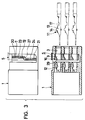
- the retainer 5 is inserted into a predetermined position in the retainer insertion groove 6, with the two fitting grooves 10 fitted respectively on the guide walls 7, as shown in Fig. 3, and then the metal terminals 11 are respectively inserted into the terminal receiving holes 3, and are pushed to inner ends thereof, so that an elastic retaining pawl 12 (see Fig. 3) formed within each receiving hole 3 is received in a retaining recess 14 formed in an upper surface of a main portion 13 of the metal terminal 11, thereby effecting a first-stage retaining in a withdrawing direction.
- a retaining step 16, formed on an upper wall of each communication hole 9, is received in a recess 17 formed adjacent to a rear end of the main portion 13, thereby effecting a second-stage retaining, as described above for the conventional construction.
- the thickness of the retainer 5 is smaller by a predetermined dimension than the width of the retainer insertion groove 6.
- a generally vertically-extending guide groove 19 for guiding the insertion of the retainer is formed in an outer surface of each of the guide walls 7 formed respectively on the opposite (right and left) sides of the retainer insertion groove 6.
- the guide groove 19 has an upper straight portion 20 and a lower straight portion 21 which are parallel to each other, and are offset relative to each other in a front-to-rear direction in such a manner that inner edges of the two straight portions are disposed in a common straight line.
- This configuration is achieved by a mold of a special design for forming the two straight portions 20 and 21, and this will be described later in detail.
- the lower end of the upper straight portion 20 is connected to the upper end of the lower straight portion 21 by a slanting portion 22 slanting toward the front side.
- An auxiliary groove 23 of a greater depth is formed in the straight portion 20, and is disposed centrally of the width thereof, and extends from the upper end thereof to the slanting portion 22.
- An auxiliary groove 24 of a greater depth is formed in the straight portion 21, and is disposed centrally of the width thereof, and extends from the lower end thereof to the slanting portion 22.
- Each of the grooves 23 and 24 has a semi-circular cross-section, and has the end formed into a semi-spherical shape. The lower end of the auxiliary groove 23 and the upper end of the auxiliary groove 24 are separated from each other, unlike the guide groove 19.
- a projection 26 of a parallelogrammic shape is formed on that surface of each of the right and left fitting grooves 10 of the retainer 5 facing that surface of the guide wall 7 having the guide groove 19 formed therein, and the projection 26 is formed at a predetermined position, and can be intimately fitted in and slide along the straight portions 20 and 21 and the slanting portion 22 of the guide groove 19.
- a projection 27 of a semi-spherical shape for fitting in the auxiliary groove 23, 24 is formed on the surface of the projection 26.
- the lower straight portion 21 is not always necessary in view of the function of this embodiment described later in detail, and also the auxiliary groove 24 may be replaced by a semi-spherical hole for receiving the projection 27 which hole is formed at the position where the upper end of the lower auxiliary groove 24 is disposed. Furthermore, it is not necessary that the inner edges of the two straight portions 20 and 21 should be disposed in a common straight line, and this configuration is adopted for the convenience of the formation of the guide groove 19 by molding.
- a pair of upper and lower slide cores x and y each having an inclined front end are used, as shown in Fig. 5, and the cores x and y serve to form the upper and lower straight portions 20 and 21, respectively, and also serve to form halves of the slanting portion 22, respectively.
- the upper and lower straight portions 20 and 21 and the slanting portion 22 are simultaneously formed by molding. Namely, the removal of a mold portion in a direction away from the front surface of the sheet of Fig. 5 is omitted, thereby reducing the manufacturing cost.
- the front edge of the retaining step 16, formed on the upper wall of each communication hole 9 in the retainer 5, is cut to form a slanting abutment surface 29 which allows a smooth pushing of the metal terminal 11.
- the retainer 5 is brought into registry with a rear portion of the retainer insertion groove 6, and is inserted thereinto.
- each projection 26 and each projection 27 of the retainer 5 are fitted respectively in the upper straight portion 20 of the guide groove 9 and the auxiliary groove 23 during the insertion, and the retainer is inserted straight downward while guided by these portions.
- a resistance is perceived, and the insertion operation is stopped once, so that the retainer 5 is stopped at a position slightly before a provisionally-retained position.
- the metal terminals 11 are inserted into the terminal receiving holes 3 of the housing 1, respectively, as described above.
- the projection 27 is disengaged from the lower end of the auxiliary groove 23, and is brought into contact with the bottom surface of the slanting portion 22 of the guide groove 19 as shown in Fig. 4A, and the projection 26 is guided along this slanting portion 22, so that the retainer 5 is slightly displaced obliquely forwardly downwardly to reach the provisionally-retained position.
- the projection 27 is held in contact with the bottom surface of the guide groove 19, as described above, and therefore because of a frictional engagement between the two, for example, when transporting a provisionally-assembled structure comprising the housing 1, the retainer 5 and the metal terminals 11, the retainer 5 will not be easily disengaged, and also the retainer 5 will be effectively prevented from being accidentally displaced into a completely-retained position.
- the slanting abutment surface 29 on the front edge of the retaining step 16 of the retainer 5 is abutted against a rear edge of the main portion 13 of the metal terminal 11 disposed adjacent to the recess 17, as shown in Fig. 4A.
- the metal terminal 11 receives a forwardly-acting pressing force to be pushed into the proper inserted position, so that the first-stage retaining by the elastic retaining pawl 12 is effected, and also the retaining step 16 of the retainer 15 is fitted in the recess 17, thereby effecting the second-stage retaining.
- the metal terminal 11 even if the metal terminal 11 is inadvertently held in a half-inserted position, the metal terminal can be automatically pushed into the proper inserted position in accordance with the displacement of the retainer 5 from the provisionally-retained position to the completely-retained position, and therefore there is no need to re-insert the metal terminal 11.
- each projection 27 of the retainer 5 into contact with the bottom surface of the slanting portion 22 of the guide groove 19, the retainer 5 can be easily locked in the provisionally-retained position in such a manner that the retainer can not be displaced upwardly and downwardly. Also, by fitting the projection 27 in the upper end of the lower auxiliary groove 24, the retainer can be held in the completely-locked position against upward movement.
- forwardly downwardly-slanting surfaces 32 and 33 which are parallel to the slanting portion 22 of the guide groove 19, and can be mated with each other, may be formed on a lower surface of a projected portion 31 formed on the upper rear edge of the retainer 5 and the upper rear edge of the retainer insertion groove 6, respectively, in which case in addition to the fitting of the projection 26 in the slanting portion 22 of the guide groove 19, a relative sliding movement between the slanting surfaces 32 and 33 serves to guide the oblique displacement of the retainer 5.
- a guide groove 19 and auxiliary grooves 23 and 24 are formed in each of two guide walls 7 provided respectively at opposite sides of a retainer insertion groove 6 in a housing 1a, and a projection 26 and a projection 27 are formed on that surface of each fitting groove 10 of the retainer 5 facing the guide wall.
- the guide groove 19 and the auxiliary grooves 23 and 24 may be provided at each fitting groove 10 of the retainer whereas the projection 26 and the projection 27 may be formed on that surface of the guide wall 7 of the retainer insertion groove 6 facing these grooves.
Abstract
Description
- This invention relates to a connector having the function of double retaining of metal terminals by a retainer, and more particularly to a connector having the function of urging half-inserted metal terminals into a proper inserted position in accordance with the insertion of the retainer.
- There are known connectors having a double retaining function to be performed by a retainer. In such a connector as shown in Fig. 7, when a metal terminal c is inserted into a terminal receiving hole b in a housing a from a rear end thereof, an elastic retaining pawl d formed on an upper wall of the terminal receiving hole b is elastically deformed by this inserted metal terminal. Then, when the metal terminal reaches a proper inserted position at the inner end of the terminal receiving hole, the retaining pawl d is received in a retaining recess e, formed in the upper surface of the metal terminal c, due to its own resilient restoring force, thereby effecting a first-stage retaining in a withdrawing direction. Then, when a retainer f, inserted into a provisionally-retained position from a lower side of the housing a in a manner to generally divide the housing, is pushed in a direction of an arrow to be retained in a completely-retained position, a retaining step g formed on the retainer f is received in a recess h formed in a lower surface of the metal terminal c, thereby effecting a second-stage retaining.
- In such a connector, the metal terminal c is inserted while elastically deforming the retaining pawl d, as described above, and therefore a considerable load is perceived halfway, and despite the fact that the metal terminal has not yet reached the proper inserted position, the inserting operation is often stopped under a mistake of facts in a half-inserted position as indicated in a broken line in Fig. 7.
- If such a situation is encountered, even when the retainer f is pushed, the retaining step g is abutted against the lower surface of the metal terminal c, so that the retainer can not be inserted. In this case, the operator becomes aware of the half-inserted condition of the metal terminal c, and it is necessary for the operator to once retract the retainer f, to re-insert the metal terminal c into the proper inserted position, and then to again push the retainer f. However, since many metal terminals c have been inserted, it is not easy to find the half-inserted terminal among these terminals. And besides, such half-inserted metal terminal is not always one, and in an extreme case, all of the metal terminals must be re-inserted, thus inviting a disadvantage that an extremely troublesome operation must be done.
- It is known from experiences that the metal terminal c is held in the half-inserted condition mainly because the retaining step g of the retainer f interferes with an end edge of a main portion i.
- The present invention has been made in view of the above problem, and an object of the invention is to correct a half-inserted condition of a metal terminal, thereby enabling mating connectors to be easily fitted together.
- The above object of the present invention has been achieved by a connector comprising a housing having terminal receiving holes each for receiving a metal terminal inserted from a rear end thereof; a retainer insertable into a retainer insertion groove which is formed in the housing in a manner to generally divide each of the terminal receiving holes, and is open to one side of the housing, the retainer having communication holes communicatable with the terminal receiving holes, respectively, and the retainer being adapted to be retained in a provisionally-retained position where each of the communication holes does not hinder the insertion and withdrawal of the metal terminal and in a completely-retained position where the retainer is engaged with the metal terminals in a manner to limit the withdrawal of the metal terminals; wherein guide grooves for guiding the insertion of the retainer are formed respectively in those surfaces of one of the housing and the retainer facing the other, whereas projections for being displaced respectively along the guide grooves are formed on the other; the retainer can be abutted against part of the metal terminal in the provisionally-retained position when the metal terminal is disposed in a half-inserted position; and each of the guide grooves is so formed that during the time when the retainer is displaced from the provisionally-retained position to the completely-retained position, the retainer can push the metal terminals from the half-inserted position into a proper inserted position.
- When the retainer is inserted into the retainer insertion groove in the housing, the retainer reaches the provisionally-retained position, with the projections guided by and moved along the guide grooves, respectively. The metal terminals are inserted, and then when the retainer is further inserted, the retainer is displaced to the completely-retained position. If the metal terminal is disposed in a half-inserted position during the displacement of the retainer from the provisionally-retained position, the retainer is abutted against part of the metal terminal, and pushes the metal terminal into a proper inserted position during the displacement of the retainer into the completely-retained position, and also the retainer retains the metal terminals against withdrawal in this position.
- Advantageous effects of the present invention will be described. Even if the metal terminal is inadvertently disposed in a half-inserted position, the metal terminal can be automatically pushed into the proper inserted position in accordance with the displacement of the retainer from the provisionally-retained position into the completely-retained position. Thus, there is no need to re-insert the metal terminal, and therefore the efficiency of the operation can be enhanced greatly.
-
- Fig. 1 is a partly-broken, exploded perspective view of one preferred embodiment of the present invention;
- Fig. 2 is a front-elevational view showing a housing and a retainer before they are assembled together;
- Fig. 3 is an explanatory view showing a condition in which the retainer is inserted to a position immediately before a provisionally-retained position;
- Fig. 4A is an explanatory view showing the retainer in the provisionally-retained position;
- Fig. 4B is an explanatory view showing the retainer in a completely-retained position;
- Fig. 5 is a view explanatory of the formation of a guide groove by molding;
- Fig. 6A is an explanatory view of another embodiment of the present invention in which the invention is applied to a female connector, showing a retainer in a provisionally-retained position;
- Fig. 6B is an explanatory view of the female connector, showing the retainer in a completely-retained position; and
- Fig. 7 is a cross-sectional view of a portion of a conventional construction.
- One preferred embodiment of the present invention, in which the invention is applied to a male connector, will now be described with reference to Figs. 1 to 5.
- In these Figures, a housing 1 includes a
body 2 of a rectangular parallelepipedic shape, and twelve (12)terminal receiving holes 3 for respectively receiving male metal terminals 11 are formed through this body, and extend from a front side to a rear side of the housing, theterminal receiving holes 3 being arranged in three columns and four rows. Aretainer insertion groove 6 for receiving aretainer 5 for retaining the metal terminals 11 in a double manner is formed in a generally central portion of an upper surface of thebody 2 in a manner to divide eachterminal receiving hole 3, andguide walls 7 are provided respectively on opposite (right and left) sides of this retainer insertion groove. -
Communication holes 9 equal in number to theterminal receiving holes 3 are formed through theretainer 5, and are communicatable with theterminal receiving holes 3, respectively. Formed respectively in opposite (right and left) sides of the retainer are downwardly-open fitting grooves 10 in which theguide walls 7 are adapted to be fitted, respectively. - The
retainer 5 is inserted into a predetermined position in theretainer insertion groove 6, with the twofitting grooves 10 fitted respectively on theguide walls 7, as shown in Fig. 3, and then the metal terminals 11 are respectively inserted into theterminal receiving holes 3, and are pushed to inner ends thereof, so that an elastic retaining pawl 12 (see Fig. 3) formed within each receivinghole 3 is received in aretaining recess 14 formed in an upper surface of amain portion 13 of the metal terminal 11, thereby effecting a first-stage retaining in a withdrawing direction. When theretainer 5 is further pushed, aretaining step 16, formed on an upper wall of eachcommunication hole 9, is received in arecess 17 formed adjacent to a rear end of themain portion 13, thereby effecting a second-stage retaining, as described above for the conventional construction. - Next, the structure of the insertion portion of the
retainer 5 of the present invention will now be described in detail. - In this embodiment, the thickness of the
retainer 5 is smaller by a predetermined dimension than the width of theretainer insertion groove 6. - A generally vertically-extending
guide groove 19 for guiding the insertion of the retainer is formed in an outer surface of each of theguide walls 7 formed respectively on the opposite (right and left) sides of theretainer insertion groove 6. As shown in Fig. 2, theguide groove 19 has an upperstraight portion 20 and a lowerstraight portion 21 which are parallel to each other, and are offset relative to each other in a front-to-rear direction in such a manner that inner edges of the two straight portions are disposed in a common straight line. This configuration is achieved by a mold of a special design for forming the twostraight portions straight portion 20 is connected to the upper end of the lowerstraight portion 21 by aslanting portion 22 slanting toward the front side. Anauxiliary groove 23 of a greater depth is formed in thestraight portion 20, and is disposed centrally of the width thereof, and extends from the upper end thereof to theslanting portion 22. Anauxiliary groove 24 of a greater depth is formed in thestraight portion 21, and is disposed centrally of the width thereof, and extends from the lower end thereof to theslanting portion 22. Each of thegrooves auxiliary groove 23 and the upper end of theauxiliary groove 24 are separated from each other, unlike theguide groove 19. - On the other hand, a
projection 26 of a parallelogrammic shape is formed on that surface of each of the right and leftfitting grooves 10 of theretainer 5 facing that surface of theguide wall 7 having theguide groove 19 formed therein, and theprojection 26 is formed at a predetermined position, and can be intimately fitted in and slide along thestraight portions slanting portion 22 of theguide groove 19. Further, aprojection 27 of a semi-spherical shape for fitting in theauxiliary groove projection 26. - With respect to the
guide groove 19, the lowerstraight portion 21 is not always necessary in view of the function of this embodiment described later in detail, and also theauxiliary groove 24 may be replaced by a semi-spherical hole for receiving theprojection 27 which hole is formed at the position where the upper end of the lowerauxiliary groove 24 is disposed. Furthermore, it is not necessary that the inner edges of the twostraight portions guide groove 19 by molding. - More specifically, for forming the
guide groove 19 by molding, a pair of upper and lower slide cores x and y each having an inclined front end are used, as shown in Fig. 5, and the cores x and y serve to form the upper and lowerstraight portions slanting portion 22, respectively. Merely by withdrawing the upper and lower cores x and y in directions of arrows, respectively, the upper and lowerstraight portions slanting portion 22 are simultaneously formed by molding. Namely, the removal of a mold portion in a direction away from the front surface of the sheet of Fig. 5 is omitted, thereby reducing the manufacturing cost. - The front edge of the retaining
step 16, formed on the upper wall of eachcommunication hole 9 in theretainer 5, is cut to form aslanting abutment surface 29 which allows a smooth pushing of the metal terminal 11. - The operation of this embodiment will now be described mainly with reference to Figs. 3 and 4.
- First, the
retainer 5 is brought into registry with a rear portion of theretainer insertion groove 6, and is inserted thereinto. At this time, eachprojection 26 and eachprojection 27 of theretainer 5 are fitted respectively in the upperstraight portion 20 of theguide groove 9 and theauxiliary groove 23 during the insertion, and the retainer is inserted straight downward while guided by these portions. When eachprojection 26 and eachprojection 27 reach the lower ends of the upperstraight portion 20 and theauxiliary groove 23, respectively, a resistance is perceived, and the insertion operation is stopped once, so that theretainer 5 is stopped at a position slightly before a provisionally-retained position. In this condition, the metal terminals 11 are inserted into theterminal receiving holes 3 of the housing 1, respectively, as described above. - Then, when the
retainer 5 is further pushed, theprojection 27 is disengaged from the lower end of theauxiliary groove 23, and is brought into contact with the bottom surface of the slantingportion 22 of theguide groove 19 as shown in Fig. 4A, and theprojection 26 is guided along this slantingportion 22, so that theretainer 5 is slightly displaced obliquely forwardly downwardly to reach the provisionally-retained position. - In this provisionally-retained position, the
projection 27 is held in contact with the bottom surface of theguide groove 19, as described above, and therefore because of a frictional engagement between the two, for example, when transporting a provisionally-assembled structure comprising the housing 1, theretainer 5 and the metal terminals 11, theretainer 5 will not be easily disengaged, and also theretainer 5 will be effectively prevented from being accidentally displaced into a completely-retained position. - If any of the metal terminals 11 has not yet reached the proper inserted position, and hence is disposed in a half-inserted position when the
retainer 5 is displaced into the above provisionally-retained position, the slantingabutment surface 29 on the front edge of the retainingstep 16 of theretainer 5 is abutted against a rear edge of themain portion 13 of the metal terminal 11 disposed adjacent to therecess 17, as shown in Fig. 4A. - In this condition, when the
retainer 5 is further pushed, theprojection 26 is guided by the remaining portion of the slantingportion 22, and theretainer 5 is further displaced obliquely forwardly downwardly, so that theretainer 5 is abutted at its lower surface against the bottom surface of theretainer insertion groove 6, and hence reaches the completely-retained position, thus stopping the displacement, as shown in Fig. 4B. At this time, theprojection 27 is fitted in the upper end of the lowerauxiliary groove 24, thereby retaining theretainer 5 against upward movement. - During the time when the
retainer 5 is displaced obliquely forwardly downwardly from the provisionally-retained position to the completely-retained position, the metal terminal 11 receives a forwardly-acting pressing force to be pushed into the proper inserted position, so that the first-stage retaining by theelastic retaining pawl 12 is effected, and also the retainingstep 16 of the retainer 15 is fitted in therecess 17, thereby effecting the second-stage retaining. - Thus, in this embodiment, even if the metal terminal 11 is inadvertently held in a half-inserted position, the metal terminal can be automatically pushed into the proper inserted position in accordance with the displacement of the
retainer 5 from the provisionally-retained position to the completely-retained position, and therefore there is no need to re-insert the metal terminal 11. - In the structure of this embodiment, by bringing each
projection 27 of theretainer 5 into contact with the bottom surface of the slantingportion 22 of theguide groove 19, theretainer 5 can be easily locked in the provisionally-retained position in such a manner that the retainer can not be displaced upwardly and downwardly. Also, by fitting theprojection 27 in the upper end of the lowerauxiliary groove 24, the retainer can be held in the completely-locked position against upward movement. - In order to confirm the direction of the
retainer 5, forwardly downwardly-slantingsurfaces portion 22 of theguide groove 19, and can be mated with each other, may be formed on a lower surface of a projectedportion 31 formed on the upper rear edge of theretainer 5 and the upper rear edge of theretainer insertion groove 6, respectively, in which case in addition to the fitting of theprojection 26 in the slantingportion 22 of theguide groove 19, a relative sliding movement between the slantingsurfaces retainer 5. - In the above embodiment, although the invention is applied to the male connector, the invention can be applied to a female connector, as shown in Fig. 6. In this case, similarly, a
guide groove 19 andauxiliary grooves guide walls 7 provided respectively at opposite sides of aretainer insertion groove 6 in ahousing 1a, and aprojection 26 and aprojection 27 are formed on that surface of eachfitting groove 10 of theretainer 5 facing the guide wall. With this arrangement, during the time when theretainer 5 is displaced from a provisionally-retained position (Fig. 6A) to a completely-retained position (Fig. 6B), thosemetal terminals 11a disposed in a half-inserted position can be pushed into a proper inserted position, as described above. - Of course, in either of the above connectors, the
guide groove 19 and theauxiliary grooves fitting groove 10 of the retainer whereas theprojection 26 and theprojection 27 may be formed on that surface of theguide wall 7 of theretainer insertion groove 6 facing these grooves.
Claims (9)
- A connector comprising:
a connector housing having terminal receiving holes each for receiving a metal terminal inserted from a rear end the connector housing, and a retainer insertion groove formed to divide each of said terminal receiving holes and to open one side of said connector housing;
a retainer insertable into said retainer insertion groove, said retainer having communication holes communicatable with said terminal receiving holes, respectively, and said retainer being adapted to be retained in a provisionally-retained position where each of said communication holes does not hinder the insertion and withdrawal of said metal terminal and in a completely-retained position where said retainer is engaged with said metal terminals in a manner to limit the withdrawal of said metal terminals;
wherein guide grooves for guiding the insertion of said retainer are formed on one of said connector housing and said retainer, whereas projections for being disposed to move respectively along said guide grooves are formed on the other; said retainer can be abutted against part of said metal terminal in said provisionally-retained position when said metal terminal is disposed in a half-inserted position; and each of said guide grooves is so formed that during the time when said retainer is moved from said provisionally-retained position to said completely-retained position, said retainer can push said metal terminals from the half-inserted position into a proper inserted position. - A connector as claimed in claim 1, wherein said connector housing further comprises a pair of guide walls at opposite sides of said retainer insertion groove.
- A connector as claimed in claim 2, wherein said retainer has tow leg portion to form fitting grooves downwardly opened to be fitted with said guide walls.
- A connector as claimed in claim 3, wherein said guide grooves are formed on said guide walls, and said projections are formed on said leg portion.
- A connector as claimed in claim 1, wherein a width of said retainer is less than a width of said retainer insertion groove by a predetermined width.
- A connector as claimed in claim 1, wherein each of said guide groves for guiding said projection has an upper straight portion and a lower straight portion which are parallel to and offset relative to each other in front-to-rear direction in a manner that inner edges of the two straight portions are aligned in a common straight line, and a slanting portion communicating said upper and lower straight portions.
- A connector as claimed in claim 6, wherein said projection has a parallelogrammic shape, a pair of sides of which contact with edges of straight portion of the guide groove, and the other pair of sides contact with edges of the slanting portion.
- A connector as claimed in claim 1, wherein said guide groove has an auxiliary groove of greater depth at centrally of the width of the guide groove.
- A connector as claimed in claim 8, wherein said projection has a semi-spherical projection to be fit with said auxiliary groove.
Applications Claiming Priority (2)
| Application Number | Priority Date | Filing Date | Title |
|---|---|---|---|
| JP1993024690U JP2581476Y2 (en) | 1993-04-13 | 1993-04-13 | connector |
| JP24690/93 | 1993-04-13 |
Publications (3)
| Publication Number | Publication Date |
|---|---|
| EP0624922A2 true EP0624922A2 (en) | 1994-11-17 |
| EP0624922A3 EP0624922A3 (en) | 1995-08-30 |
| EP0624922B1 EP0624922B1 (en) | 1998-05-06 |
Family
ID=12145171
Family Applications (1)
| Application Number | Title | Priority Date | Filing Date |
|---|---|---|---|
| EP94105632A Expired - Lifetime EP0624922B1 (en) | 1993-04-13 | 1994-04-12 | Connector |
Country Status (4)
| Country | Link |
|---|---|
| US (1) | US5464356A (en) |
| EP (1) | EP0624922B1 (en) |
| JP (1) | JP2581476Y2 (en) |
| DE (1) | DE69410009T2 (en) |
Cited By (6)
| Publication number | Priority date | Publication date | Assignee | Title |
|---|---|---|---|---|
| FR2733364A1 (en) * | 1995-04-19 | 1996-10-25 | Cinch Connecteurs Sa | Electrical connector housing element providing secure locking |
| EP0740366A2 (en) * | 1995-04-24 | 1996-10-30 | SUMITOMO WIRING SYSTEMS, Ltd. | A connector, a method for manufacturing the same, a device for molding the same,and a method for mounting a retainer |
| US5595509A (en) * | 1995-08-14 | 1997-01-21 | Molex Incorporated | Electrical connector with terminal position assurance system |
| EP0899822A2 (en) * | 1997-08-11 | 1999-03-03 | Framatome Connectors International | Plug-in connector arrangement |
| EP1033788A1 (en) * | 1999-03-03 | 2000-09-06 | Sumitomo Wiring Systems, Ltd. | Connector with secondary locking |
| DE102007032562B4 (en) * | 2006-07-18 | 2011-02-17 | Sumitomo Wiring Systems, Ltd., Yokkaichi-shi | Connector and connector assembly method |
Families Citing this family (30)
| Publication number | Priority date | Publication date | Assignee | Title |
|---|---|---|---|---|
| DE4407950C1 (en) * | 1994-03-09 | 1995-08-17 | Siemens Ag | Electrical connector with a locking device with contact feed |
| JP3391419B2 (en) * | 1994-04-20 | 2003-03-31 | 住友電装株式会社 | connector |
| JPH08106944A (en) * | 1994-10-03 | 1996-04-23 | Tokai Rika Co Ltd | Electric connector and housing of this electric connector |
| JP3765510B2 (en) * | 1997-02-10 | 2006-04-12 | 矢崎総業株式会社 | connector |
| US5967859A (en) * | 1997-12-10 | 1999-10-19 | Molex Incorporated | Electrical connector assembly with terminal retainer system |
| JP3224369B2 (en) * | 1998-07-16 | 2001-10-29 | 日本圧着端子製造株式会社 | Connector terminals and housing |
| JP3247344B2 (en) * | 1998-08-20 | 2002-01-15 | 日本圧着端子製造株式会社 | Connector housing and connector using the same |
| DE19929928B4 (en) * | 1999-06-29 | 2006-08-17 | Delphi Technologies, Inc., Troy | Socket for an electrical connection device |
| JP3799542B2 (en) * | 2000-12-01 | 2006-07-19 | 住友電装株式会社 | connector |
| JP3666358B2 (en) * | 2000-05-24 | 2005-06-29 | 住友電装株式会社 | Connector housing |
| JP3755429B2 (en) | 2001-06-19 | 2006-03-15 | 住友電装株式会社 | connector |
| US6540566B1 (en) * | 2002-01-31 | 2003-04-01 | Hon Hai Precision Ind. Co., Ltd. | Electrical connector |
| JP4126179B2 (en) * | 2002-02-01 | 2008-07-30 | 住友電装株式会社 | connector |
| JP2003297490A (en) * | 2002-04-08 | 2003-10-17 | Sumitomo Wiring Syst Ltd | Connector |
| US6780069B2 (en) * | 2002-12-12 | 2004-08-24 | 3M Innovative Properties Company | Connector assembly |
| JP2004303543A (en) * | 2003-03-31 | 2004-10-28 | Sumitomo Wiring Syst Ltd | Connector |
| JP4100255B2 (en) * | 2003-05-28 | 2008-06-11 | 住友電装株式会社 | connector |
| US7651359B2 (en) * | 2006-09-14 | 2010-01-26 | 3M Innovative Properties Company | Electrical connector assembly |
| JP4730282B2 (en) * | 2006-10-26 | 2011-07-20 | 住友電装株式会社 | connector |
| JP4252603B2 (en) * | 2007-01-31 | 2009-04-08 | タイコエレクトロニクスアンプ株式会社 | Electrical connector |
| JP2009021159A (en) * | 2007-07-13 | 2009-01-29 | Tyco Electronics Amp Kk | Electric connector assembly, and male connector |
| EP2051335B1 (en) * | 2007-10-19 | 2011-09-14 | Sumitomo Wiring Systems, Ltd. | A connector |
| JP4636072B2 (en) * | 2007-10-19 | 2011-02-23 | 住友電装株式会社 | connector |
| US8172624B2 (en) * | 2008-12-05 | 2012-05-08 | Hubbell Incorporated | Wiring device assembly with contact stabilizing structure |
| JP6792797B2 (en) * | 2017-03-01 | 2020-12-02 | 株式会社オートネットワーク技術研究所 | Terminal unit |
| CN107221811B (en) * | 2017-07-03 | 2023-06-02 | 凡甲电子(苏州)有限公司 | Electric connector and electric connector combination with same |
| JP7042402B2 (en) * | 2018-12-27 | 2022-03-28 | 株式会社オートネットワーク技術研究所 | connector |
| JP7318311B2 (en) * | 2019-05-29 | 2023-08-01 | 株式会社オートネットワーク技術研究所 | female connector and connector |
| US11456553B2 (en) * | 2019-09-19 | 2022-09-27 | J.S.T. Corporation | Low profile high voltage connector and method for assemblying thereof |
| KR20220008630A (en) * | 2020-07-14 | 2022-01-21 | 현대자동차주식회사 | Connector apparatus |
Citations (5)
| Publication number | Priority date | Publication date | Assignee | Title |
|---|---|---|---|---|
| GB2218272A (en) * | 1988-01-31 | 1989-11-08 | Amp Inc | Electrical connector with contact latching plate |
| US5120269A (en) * | 1990-08-01 | 1992-06-09 | Yazaki Corporation | Electrical connector with terminal retaining member |
| US5160283A (en) * | 1991-12-04 | 1992-11-03 | Molex Incorporated | Terminal positioning assurance device |
| US5167534A (en) * | 1991-04-04 | 1992-12-01 | Yazaki Corporation | Connector with double lock mechanism |
| US5186662A (en) * | 1990-05-30 | 1993-02-16 | Amp Incorporated | Double locking-type electrical connector |
Family Cites Families (3)
| Publication number | Priority date | Publication date | Assignee | Title |
|---|---|---|---|---|
| JPS6454678A (en) * | 1987-08-26 | 1989-03-02 | Yazaki Corp | Connector |
| US5203722A (en) * | 1990-09-28 | 1993-04-20 | Amp Incorporated | Double-lock electrical connector |
| JP2541164Y2 (en) * | 1991-05-13 | 1997-07-09 | 住友電装株式会社 | connector |
-
1993
- 1993-04-13 JP JP1993024690U patent/JP2581476Y2/en not_active Expired - Fee Related
-
1994
- 1994-04-06 US US08/223,974 patent/US5464356A/en not_active Expired - Lifetime
- 1994-04-12 EP EP94105632A patent/EP0624922B1/en not_active Expired - Lifetime
- 1994-04-12 DE DE69410009T patent/DE69410009T2/en not_active Expired - Fee Related
Patent Citations (5)
| Publication number | Priority date | Publication date | Assignee | Title |
|---|---|---|---|---|
| GB2218272A (en) * | 1988-01-31 | 1989-11-08 | Amp Inc | Electrical connector with contact latching plate |
| US5186662A (en) * | 1990-05-30 | 1993-02-16 | Amp Incorporated | Double locking-type electrical connector |
| US5120269A (en) * | 1990-08-01 | 1992-06-09 | Yazaki Corporation | Electrical connector with terminal retaining member |
| US5167534A (en) * | 1991-04-04 | 1992-12-01 | Yazaki Corporation | Connector with double lock mechanism |
| US5160283A (en) * | 1991-12-04 | 1992-11-03 | Molex Incorporated | Terminal positioning assurance device |
Cited By (12)
| Publication number | Priority date | Publication date | Assignee | Title |
|---|---|---|---|---|
| FR2733364A1 (en) * | 1995-04-19 | 1996-10-25 | Cinch Connecteurs Sa | Electrical connector housing element providing secure locking |
| EP0740366A2 (en) * | 1995-04-24 | 1996-10-30 | SUMITOMO WIRING SYSTEMS, Ltd. | A connector, a method for manufacturing the same, a device for molding the same,and a method for mounting a retainer |
| EP0740366A3 (en) * | 1995-04-24 | 1998-01-07 | SUMITOMO WIRING SYSTEMS, Ltd. | A connector, a method for manufacturing the same, a device for molding the same,and a method for mounting a retainer |
| US5911935A (en) * | 1995-04-24 | 1999-06-15 | Sumitomo Wiring Systems, Ltd. | Method for manufacturing a connector and a retainer |
| US6115915A (en) * | 1995-04-24 | 2000-09-12 | Sumitomo Wiring Systems, Ltd. | Method for mounting a retainer into a connector housing |
| US6318991B1 (en) | 1995-04-24 | 2001-11-20 | Sumitomo Wiring Systems | Molding device for making a connector |
| US5595509A (en) * | 1995-08-14 | 1997-01-21 | Molex Incorporated | Electrical connector with terminal position assurance system |
| EP0899822A2 (en) * | 1997-08-11 | 1999-03-03 | Framatome Connectors International | Plug-in connector arrangement |
| EP0899822A3 (en) * | 1997-08-11 | 1999-11-03 | Framatome Connectors International | Plug-in connector arrangement |
| EP1033788A1 (en) * | 1999-03-03 | 2000-09-06 | Sumitomo Wiring Systems, Ltd. | Connector with secondary locking |
| US6261133B1 (en) | 1999-03-03 | 2001-07-17 | Sumitomo Wiring Systems, Ltd. | Connector |
| DE102007032562B4 (en) * | 2006-07-18 | 2011-02-17 | Sumitomo Wiring Systems, Ltd., Yokkaichi-shi | Connector and connector assembly method |
Also Published As
| Publication number | Publication date |
|---|---|
| DE69410009T2 (en) | 1998-09-17 |
| DE69410009D1 (en) | 1998-06-10 |
| EP0624922B1 (en) | 1998-05-06 |
| EP0624922A3 (en) | 1995-08-30 |
| US5464356A (en) | 1995-11-07 |
| JPH0679075U (en) | 1994-11-04 |
| JP2581476Y2 (en) | 1998-09-21 |
Similar Documents
| Publication | Publication Date | Title |
|---|---|---|
| EP0624922B1 (en) | Connector | |
| US7204725B2 (en) | Connector and method of assembling it | |
| EP0669679B1 (en) | Cam-equipped connector | |
| US6644992B2 (en) | Lever-type connector | |
| US5437558A (en) | Connector having skirt with holes to receive plug pins and alignment pin | |
| US5613881A (en) | Connector | |
| US6244880B1 (en) | Low-insertion force connector | |
| US6241542B1 (en) | Connector with shorting terminal | |
| US7297032B2 (en) | Combined connector | |
| US5061210A (en) | Connector with terminal retainer | |
| US6811451B2 (en) | Connector | |
| US6497591B2 (en) | Connector | |
| JP2946000B2 (en) | Electrical connector | |
| EP2506368A1 (en) | Connector comprising a retainer movable between a partial and a full locking positions | |
| US6655999B2 (en) | Connector and a method of assembling it | |
| US6599154B2 (en) | Connector with obliquely Moveable retainer | |
| EP1085617B1 (en) | A connector | |
| US6641437B2 (en) | Connector | |
| US6976874B2 (en) | Terminal fitting and connector provided therewith | |
| US6851987B2 (en) | Connector | |
| US6551146B2 (en) | Connector and a method for assembling a connector | |
| US20020115339A1 (en) | Connector and a method of assembling a connector | |
| US6589083B2 (en) | Connector | |
| US6520786B2 (en) | Connector | |
| US6811452B2 (en) | Connector with a retainer |
Legal Events
| Date | Code | Title | Description |
|---|---|---|---|
| PUAI | Public reference made under article 153(3) epc to a published international application that has entered the european phase |
Free format text: ORIGINAL CODE: 0009012 |
|
| AK | Designated contracting states |
Kind code of ref document: A2 Designated state(s): DE GB |
|
| PUAL | Search report despatched |
Free format text: ORIGINAL CODE: 0009013 |
|
| AK | Designated contracting states |
Kind code of ref document: A3 Designated state(s): DE GB |
|
| 17P | Request for examination filed |
Effective date: 19951027 |
|
| 17Q | First examination report despatched |
Effective date: 19961120 |
|
| GRAG | Despatch of communication of intention to grant |
Free format text: ORIGINAL CODE: EPIDOS AGRA |
|
| GRAG | Despatch of communication of intention to grant |
Free format text: ORIGINAL CODE: EPIDOS AGRA |
|
| GRAH | Despatch of communication of intention to grant a patent |
Free format text: ORIGINAL CODE: EPIDOS IGRA |
|
| GRAH | Despatch of communication of intention to grant a patent |
Free format text: ORIGINAL CODE: EPIDOS IGRA |
|
| GRAA | (expected) grant |
Free format text: ORIGINAL CODE: 0009210 |
|
| AK | Designated contracting states |
Kind code of ref document: B1 Designated state(s): DE GB |
|
| REF | Corresponds to: |
Ref document number: 69410009 Country of ref document: DE Date of ref document: 19980610 |
|
| PLBE | No opposition filed within time limit |
Free format text: ORIGINAL CODE: 0009261 |
|
| STAA | Information on the status of an ep patent application or granted ep patent |
Free format text: STATUS: NO OPPOSITION FILED WITHIN TIME LIMIT |
|
| 26N | No opposition filed | ||
| REG | Reference to a national code |
Ref country code: GB Ref legal event code: IF02 |
|
| PGFP | Annual fee paid to national office [announced via postgrant information from national office to epo] |
Ref country code: GB Payment date: 20020410 Year of fee payment: 9 |
|
| PG25 | Lapsed in a contracting state [announced via postgrant information from national office to epo] |
Ref country code: GB Free format text: LAPSE BECAUSE OF NON-PAYMENT OF DUE FEES Effective date: 20030412 |
|
| GBPC | Gb: european patent ceased through non-payment of renewal fee |
Effective date: 20030412 |
|
| PGFP | Annual fee paid to national office [announced via postgrant information from national office to epo] |
Ref country code: DE Payment date: 20080417 Year of fee payment: 15 |
|
| PG25 | Lapsed in a contracting state [announced via postgrant information from national office to epo] |
Ref country code: DE Free format text: LAPSE BECAUSE OF NON-PAYMENT OF DUE FEES Effective date: 20091103 |