EP0623712A2 - Device for removing separable matter from a liquid - Google Patents
Device for removing separable matter from a liquid Download PDFInfo
- Publication number
- EP0623712A2 EP0623712A2 EP94106638A EP94106638A EP0623712A2 EP 0623712 A2 EP0623712 A2 EP 0623712A2 EP 94106638 A EP94106638 A EP 94106638A EP 94106638 A EP94106638 A EP 94106638A EP 0623712 A2 EP0623712 A2 EP 0623712A2
- Authority
- EP
- European Patent Office
- Prior art keywords
- separating surface
- screw conveyor
- axis
- conveyor
- separated
- Prior art date
- Legal status (The legal status is an assumption and is not a legal conclusion. Google has not performed a legal analysis and makes no representation as to the accuracy of the status listed.)
- Withdrawn
Links
- 239000007788 liquid Substances 0.000 title claims description 5
- 238000000926 separation method Methods 0.000 claims description 36
- 239000000463 material Substances 0.000 claims description 20
- 238000003780 insertion Methods 0.000 claims description 11
- 230000037431 insertion Effects 0.000 claims description 11
- 239000012530 fluid Substances 0.000 abstract 1
- XLYOFNOQVPJJNP-UHFFFAOYSA-N water Substances O XLYOFNOQVPJJNP-UHFFFAOYSA-N 0.000 description 5
- XEEYBQQBJWHFJM-UHFFFAOYSA-N Iron Chemical compound [Fe] XEEYBQQBJWHFJM-UHFFFAOYSA-N 0.000 description 2
- 239000000919 ceramic Substances 0.000 description 2
- 238000004065 wastewater treatment Methods 0.000 description 2
- 229910000831 Steel Inorganic materials 0.000 description 1
- 230000001174 ascending effect Effects 0.000 description 1
- 230000005540 biological transmission Effects 0.000 description 1
- 229910010293 ceramic material Inorganic materials 0.000 description 1
- 238000010276 construction Methods 0.000 description 1
- 230000007423 decrease Effects 0.000 description 1
- 238000009434 installation Methods 0.000 description 1
- 229910052742 iron Inorganic materials 0.000 description 1
- 238000012986 modification Methods 0.000 description 1
- 230000004048 modification Effects 0.000 description 1
- 239000010841 municipal wastewater Substances 0.000 description 1
- 244000144977 poultry Species 0.000 description 1
- 239000010865 sewage Substances 0.000 description 1
- 239000010959 steel Substances 0.000 description 1
- 239000004753 textile Substances 0.000 description 1
Images
Classifications
-
- E—FIXED CONSTRUCTIONS
- E03—WATER SUPPLY; SEWERAGE
- E03F—SEWERS; CESSPOOLS
- E03F5/00—Sewerage structures
- E03F5/14—Devices for separating liquid or solid substances from sewage, e.g. sand or sludge traps, rakes or grates
-
- B—PERFORMING OPERATIONS; TRANSPORTING
- B01—PHYSICAL OR CHEMICAL PROCESSES OR APPARATUS IN GENERAL
- B01D—SEPARATION
- B01D33/00—Filters with filtering elements which move during the filtering operation
- B01D33/06—Filters with filtering elements which move during the filtering operation with rotary cylindrical filtering surfaces, e.g. hollow drums
- B01D33/11—Filters with filtering elements which move during the filtering operation with rotary cylindrical filtering surfaces, e.g. hollow drums arranged for outward flow filtration
-
- B—PERFORMING OPERATIONS; TRANSPORTING
- B01—PHYSICAL OR CHEMICAL PROCESSES OR APPARATUS IN GENERAL
- B01D—SEPARATION
- B01D33/00—Filters with filtering elements which move during the filtering operation
- B01D33/27—Filters with filtering elements which move during the filtering operation with rotary filtering surfaces, which are neither cylindrical nor planar, e.g. helical surfaces
- B01D33/275—Filters with filtering elements which move during the filtering operation with rotary filtering surfaces, which are neither cylindrical nor planar, e.g. helical surfaces using contiguous impervious surfaces
-
- B—PERFORMING OPERATIONS; TRANSPORTING
- B01—PHYSICAL OR CHEMICAL PROCESSES OR APPARATUS IN GENERAL
- B01D—SEPARATION
- B01D33/00—Filters with filtering elements which move during the filtering operation
- B01D33/44—Regenerating the filter material in the filter
-
- B—PERFORMING OPERATIONS; TRANSPORTING
- B01—PHYSICAL OR CHEMICAL PROCESSES OR APPARATUS IN GENERAL
- B01D—SEPARATION
- B01D33/00—Filters with filtering elements which move during the filtering operation
- B01D33/44—Regenerating the filter material in the filter
- B01D33/46—Regenerating the filter material in the filter by scrapers, brushes nozzles or the like acting on the cake-side of the filtering element
- B01D33/466—Regenerating the filter material in the filter by scrapers, brushes nozzles or the like acting on the cake-side of the filtering element scrapers
-
- B—PERFORMING OPERATIONS; TRANSPORTING
- B01—PHYSICAL OR CHEMICAL PROCESSES OR APPARATUS IN GENERAL
- B01D—SEPARATION
- B01D33/00—Filters with filtering elements which move during the filtering operation
- B01D33/80—Accessories
- B01D33/801—Driving means, shaft packing systems or the like
-
- B—PERFORMING OPERATIONS; TRANSPORTING
- B01—PHYSICAL OR CHEMICAL PROCESSES OR APPARATUS IN GENERAL
- B01D—SEPARATION
- B01D2201/00—Details relating to filtering apparatus
- B01D2201/28—Position of the filtering element
- B01D2201/287—Filtering elements with a vertical or inclined rotation or symmetry axis
-
- B—PERFORMING OPERATIONS; TRANSPORTING
- B01—PHYSICAL OR CHEMICAL PROCESSES OR APPARATUS IN GENERAL
- B01D—SEPARATION
- B01D29/00—Filters with filtering elements stationary during filtration, e.g. pressure or suction filters, not covered by groups B01D24/00 - B01D27/00; Filtering elements therefor
- B01D29/44—Edge filtering elements, i.e. using contiguous impervious surfaces
- B01D29/46—Edge filtering elements, i.e. using contiguous impervious surfaces of flat, stacked bodies
Definitions
- the invention relates to a device for removing material to be separated from a liquid, with an inclined, liquid-permeable and circumferentially driven separating surface, which has an open end on the inflow side and a preferably closed end face on the inflow side, with an end face arranged parallel to the separating surface and leading to a discharge point for the separated material.
- a screw conveyor with a feed hopper, housing, shaft and conveyor helix conveyor for the material to be separated, and with a detachment device arranged above the feed hopper for the material to be separated from the separation surface.
- the device is used in particular to remove floating and / or floating material from channels in sewage treatment plants, but can also be used in other areas, for example in the textile industry, in slaughterhouses, poultry farms, etc.
- a device of the type described above is known from DE-PS 36 30 755.
- the separating surface is formed in the shape of a cylinder jacket and has a circumferentially driven collecting grate, which consists of a large number of annular disks which are arranged along the circumference at a distance to form a slot.
- a clearing wiper is provided as the steel loosening device, which at least partially engages in the slots between the ring disks.
- the conveying section for the material to be separated which is designed as a screw conveyor device with a feed hopper, housing, shaft and conveying helix, is arranged in the middle of the separating surface, that is to say with its axis coaxial with the axis of the cylindrical jacket-shaped separating surface.
- the device has two drives, namely a first for the screw conveyor and a second for the separating surface.
- the stowage height is limited by the arrangement of the front wall of the hopper, ie the front of the
- the separation surface of the pent-up water level must not be higher or rise than the upper edge of the front wall of the insertion funnel, so that already separated and thrown-in separation material is not washed out by the liquid from the insertion funnel.
- the axial offset of the insertion funnel downwards ensures that all of the separating material which is released from the detachment device and thrown into the insertion funnel also reaches the latter, but at the same time the permissible stowage height is reduced again.
- Another disadvantage is that this limitation of the damming height, the separation area in the upper area can only be used partially. In this respect, an increase in the effectively usable separation area cannot be achieved with such a device by extending the separation area parallel to its axis. Although it is possible to reduce the angle of the inclination of the axis of the device to the horizontal plane in order thereby to be able to effectively use further surface areas of the separation surface for separation purposes, this disadvantageously increases the overall length of the device when the material to be separated is at a certain level must be raised.
- a similar device is also known from DE-PS 34 20 157.
- a common drive is provided for the screw conveyor and for the separating surface, the drive being transmitted to the separating surface by means of a drive arm which connects the separating surface to the shaft of the screw conveyor.
- the coaxial arrangement of the axes of the screw conveyor device on the one hand and of the separating surface on the other hand is also present here.
- This problem results in the object of the invention to increase the effectively usable separation area in a device of the type described at the outset, without having to change the diameter and thus the channel width at the same time.
- this is achieved in a device of the type described in the introduction in that the axis of the screw conveyor device is arranged offset above the axis of the rotating driven separating surface and preferably at least approximately parallel to it.
- the invention is therefore based on the idea of detaching the axis of the screw conveyor from the axis of the rotating driven separating surface and arranging it in a region above the axis of the separating surface.
- the axis of the screw conveyor does not necessarily have to run perpendicularly above the axis of the separation surface, and it is also not absolutely necessary to maintain the parallelism of the axes. Rather, the arrangement can also be made for example be that the axis of the screw conveyor within a z.
- the feed hopper of the screw conveyor can be provided with constant side walls formed over its length. If the parallel arrangement is left somewhat, this can be carried out in such a way that the side wall of the insertion funnel increases somewhat in the conveying direction, which takes into account on the one hand the increasing amount of material to be separated in the insertion funnel and ultimately the end wall of the insertion funnel facing the jammed water with its upper one Edge is raised particularly far, so that the permissible stowage height is raised particularly far, whereby on the other hand additional areas of the separating surface can be effectively used, ie the water can flow through them.
- a major advantage of the new device can be seen in the fact that it allows the damming height to be increased without changing the channel width and the diameter of the separating surface. With this possibility of an increased stowage height, there is at the same time the further advantage that the separating surface can also be made axially comparatively longer and, as a result, additional surface areas can also be used for separating purposes.
- the separation surface can be rotatably mounted on the housing of the screw conveyor.
- the housing of the screw conveyor is arranged to stand still anyway and is therefore available for storage and support purposes.
- the support and storage takes place at least in the area of the closed end wall of the separation surface, but can also include the area of the open end wall of the separation surface.
- the separating surface can have a cylindrical, non-circular or upward oval shape. In all of these cases it is possible to arrange the axis of the screw conveyor on the one hand and the axis of the separation surface independently of one another.
- a cylindrical jacket-shaped separation surface is used when the separation surface itself is largely rigid, as is the case with a basket made of rolled flat iron or wedge-shaped rods.
- the cylindrical jacket-shaped separating surface can also be designed as a strainer basket, as a basket made of filter material or the like. If the separating surface is formed from mutually movable members, there is also a non-circular shape, e.g. B. in hexagon shape. Even oval, elongated designs are possible, which are then arranged at an angle to increase the permissible stowage height and the effectively usable separation area.
- the detachment device which is driven with the rotating Separation surface comes into operative connection, can be designed as a brush, nozzle strip with water, steam, compressed air, as a stationary scraper or the like.
- the detachment can also be done by vibration. Although it is generally located on the outside of the separation surface, it is assigned to a location relative to the insertion funnel of the offset screw conveyor.
- the separating surface can be supported in the region of the end wall on at least three support arms which are fitted with rollers and which have different lengths according to the axial offset.
- the rigid or movable separation surface is then guided over the fixed rollers, the support arms being supported on the housing of the screw conveyor.
- the support arms have different lengths due to the axial offset.
- support arms in the area of the open end wall.
- These support arms can also be built on the housing of the screw conveyor, can be provided with rollers at their free ends facing the separating surface and can form a second bearing for the separating surface.
- the separation surface can have a length / diameter ratio in the range of approximately 1: 1 to 2: 1. While a length / diameter ratio of approximately 1: 1 has previously been used in the known devices, the new arrangement allows the length / diameter ratio to be increased up to approximately 2: 1 with a constant installation angle of the inclination of the axis of the separation surface. This means that the separating surface can be built comparatively considerably longer, which means that it can be used effectively Area areas of the separation area are enlarged.
- the separating surface itself can be designed as a sieve basket, as a collecting grate, as a link chain rake with conveyor hooks or the like.
- a corresponding screen basket can also be formed from filter material, in particular ceramic material.
- Separate drives can be provided for the screw conveyor device on the one hand and the separating surface on the other hand, so that there is advantageously the possibility of realizing different adapted speeds and speeds on the separating surface on the one hand and on the screw conveyor device on the other hand.
- the drive for the separating surface can also be arranged or mounted on the housing of the screw conveyor device, so that separate storage is not necessary.
- the device according to FIG. 1 has a separating surface 1 designed in the shape of a cylinder jacket, which can be designed as a circumferential screen basket.
- the separation surface 1 is arranged with its axis 2 inclined at an angle of approximately 45 ° in a channel 3.
- the width of the channel 3 corresponds to the diameter of the separating surface 1.
- the separating surface 1 has a closed end surface 4 at its upper end and an open end surface 5 at its lower end, through which the liquid loaded with the separating material flows according to arrow 6.
- the separating face 1 has an extension 7 which serves for the mounting and the attack of a drive 8.
- Support arms 9 and 10 are provided here, which carry rollers 11 and 12 on their ends facing the extension 7, on which the extension 7 rolls.
- a ring gear 13 which cooperates with a pinion 14 (FIG. 2) which sits on a shaft 15 which is driven by a motor 16 with a gear 17.
- Both the motor 16 with gear 17, which form the essential parts of the drive 8, and the support arms 9 and 10 are arranged and supported on a housing 18 of a screw conveyor device 19.
- the screw conveyor device 19 has an axis 20 which, according to the embodiment according to FIG. 1, is arranged parallel to the axis 2 of the separation surface 1 and is displaced upwards.
- the remaining parts of the check conveyor device 19, namely a shaft 21, a conveyor spiral 22 and a Throw-in funnels 23 with an end wall 24 facing the channel 3 are provided correspondingly offset from the axis 2 of the separating surface 1.
- Axis 20 lies above a plane through axis 2 perpendicular to the plane of the drawing. It is not absolutely necessary for the axis 20 to be perpendicular to the axis 2. It is important that the screw conveyor 19 is provided with its axis 20 offset upwards to the axis 2. In the area of the feed hopper 23, the conveyor helix 22 is arranged without a shaft.
- the upper edge of the end wall 24 of the insertion funnel 23 determines the maximum stowage height and thus also the size of the partial area of the separating surface 1 which can be effectively flowed through and thus used. It can be seen that the effective partial area decreases in the direction of the axis 2 from bottom to top. However, the higher the damming height can be designed, the larger the effectively usable partial area of the separation area 1.
- the upper part of the screw conveyor 19 is not shown in Figure 1. It can be designed similarly to the state of the art. For the sake of clarity, a separate drive for the shaft 21 and the conveyor spiral 22, as is usually placed in the free end region of the housing 18, is also not shown.
- Support arms 25 with rollers 26 can also be arranged in the lower region of the separating surface 1, that is to say in the region of the open end surface 5, on which the cylindrical jacket-shaped separating surface 1 rolls.
- the support arms 25 are supported on the hopper 23, which merges into the housing 18 of the screw conveyor 19.
- FIG 3 are different execution options for a cylindrical jacket-shaped separation surface 1 is shown. This can consist of curved flat bars 27, of wedge-shaped bars 28, of filter material 29 or of filter ceramic 30.
- FIG. 4 shows again exactly that the axis 20 is no longer arranged coaxially to the axis 2, but is offset upwards into a semicircular space.
- the separating surface 1 is driven in accordance with arrow 31 in one or the other direction of rotation, which can be done continuously or in cycles.
- a detachment device 32 (FIG. 1) is provided in the upper area and stationary with respect to the rotatingly driven separation surface 1. which is provided continuously over the length of the separating surface 1 and consists of a brush. a nozzle bar. can consist of swivel wipers or the like.
- the detaching device 32 is arranged relative to the insertion funnel 23. d. H.
- the detaching device 32 is also provided on the outer circumference of the separating surface 1.
- the separating surface 1 is designed as a link belt rake and is composed of individual parts which are movable relative to one another.
- the separating surface 1 is also driven here by the drive 8.
- Rollers 33 and 34 are arranged so that the separating surface 1 is stretched and guided in the form of a hexagon, as is particularly the case in FIG. 7 is recognizable.
- the separating surface 1 can be provided with catch hooks 35, which promote the upward conveyance of the material to be separated on the inside of the separating surface 1.
- the axis 20 can be arranged offset and laterally of the axis 2.
- the detaching device 32 is also provided accordingly.
Landscapes
- Chemical & Material Sciences (AREA)
- Chemical Kinetics & Catalysis (AREA)
- Health & Medical Sciences (AREA)
- Life Sciences & Earth Sciences (AREA)
- Engineering & Computer Science (AREA)
- Hydrology & Water Resources (AREA)
- Public Health (AREA)
- Water Supply & Treatment (AREA)
- Screw Conveyors (AREA)
- Combined Means For Separation Of Solids (AREA)
- Filtration Of Liquid (AREA)
- Sewage (AREA)
Abstract
Description
Die Erfindung betrifft eine Vorrichtung zum Entfernen von Abscheidegut aus einer Flüssigkeit, mit einer schräggestellten, flüssigkeitsdurchlässigen und umlaufend angetriebenen Abscheidefläche, die anströmseitig eine offene und abströmseitig eine vorzugsweise geschlossene Stirnfläche aufweist, mit einer parallel zur Abscheidefläche angeordneten, zu einer Abwurfstelle für das Abscheidegut führenden, als Schneckenfördereinrichtung mit Einwurftrichter, Gehäuse, Welle und Förderwendel ausgebildeten Förderstrecke für das Abscheidegut, und mit einer über dem Einwurftrichter angeordneten Ablöseeinrichtung für das Abscheidegut von der Abscheidefläche. Die Vorrichtung dient insbesondere zum Entfernen von Schwimm- und/oder Schwebegut aus Gerinnen von Kläranlagen, kann jedoch auch in anderen Bereichen, beispielsweise in der Textilindustrie, in Schlachthöfen, Geflügelfarmen usw. verwendet werden.The invention relates to a device for removing material to be separated from a liquid, with an inclined, liquid-permeable and circumferentially driven separating surface, which has an open end on the inflow side and a preferably closed end face on the inflow side, with an end face arranged parallel to the separating surface and leading to a discharge point for the separated material. as a screw conveyor with a feed hopper, housing, shaft and conveyor helix conveyor for the material to be separated, and with a detachment device arranged above the feed hopper for the material to be separated from the separation surface. The device is used in particular to remove floating and / or floating material from channels in sewage treatment plants, but can also be used in other areas, for example in the textile industry, in slaughterhouses, poultry farms, etc.
Eine Vorrichtung der eingangs beschriebenen Art ist aus der DE-PS 36 30 755 bekannt. Dort ist die Abscheidefläche zylindermantelförmig ausgebildet und weist einen umlaufend angetriebenen Fangrost auf, der aus einer Vielzahl von Ringscheiben besteht, die über den Umfang durchgehend mit Abstand zueinander schlitzbildend angeordnet sind. Als Ahlöseeinrichtung ist ein Räumabstreifer vorgesehen, der in die Schlitze zwischen den Ringscheiben zumindest teilweise eingreift. Die als Schneckenfördereinrichtung mit Einwurftrichter, Gehäuse, Welle und Förderwendel ausgebildete Förderstrecke für das Abscheidegut ist in der Mitte der Abscheidefläche, also mit ihrer Achse koaxial zu der Achse der zylindermantelförmigen Abscheidefläche angeordnet. Die Vorrichtung besitzt zwei Antriebe, nämlich einen ersten für die Schneckenfördereinrichtung und einen zweiten für die Abscheidefläche. Bei dieser bekannten Vorrichtung ist die Einstauhöhe durch die Anordnung der Stirnwand des Einwurftrichters begrenzt, d. h. der vor der Abscheidefläche aufgestaute Wasserspiegel darf nicht höher liegen oder steigen als die Oberkante der Stirnwand des Einwurftrichters, damit bereits abgeschiedenes und in den Einwurftrichter eingeworfenes Abscheidegut nicht durch die Flüssigkeit aus dem Einwurftrichter ausgeschwemmt wird. Durch den axialen Versatz des Einwurftrichters nach unten wird zwar sichergestellt, daß sämtliches Abscheidegut, welches von der Ablöseeinrichtung gelöst und in den Einwurftrichter abgeworfen wird, auch in diesen gelangt, jedoch wird dadurch gleichzeitig die zulässige Einstauhöhe nochmals verringert. Weiterhin ist nachteilig, daß durch diese Begrenzung der Einstauhöhe die Abscheidefläche im oberen Bereich nur teilweise genutzt werden kann. Insoweit kann auch eine Vergrößerung der effektiv nutzbaren Abscheidefläche bei einer solchen Vorrichtung nicht dadurch erreicht werden, daß die Abscheidefläche parallel zu ihrer Achse verlängert wird. Zwar ist es möglich, den Winkel der Schrägstellung der Achse der Vorrichtung zur Horizontalebene zu verkleinern, um dadurch weitere Flächenbereiche der Abscheidefläche effektiv zu Abscheidezwecken nutzen zu können, jedoch verlängert sich dadurch in nachteiliger Weise die Baulänge der Vorrichtung, wenn das Abscheidegut auf eine bestimmte Niveauhöhe angehoben werden muß.A device of the type described above is known from DE-PS 36 30 755. There, the separating surface is formed in the shape of a cylinder jacket and has a circumferentially driven collecting grate, which consists of a large number of annular disks which are arranged along the circumference at a distance to form a slot. A clearing wiper is provided as the steel loosening device, which at least partially engages in the slots between the ring disks. The conveying section for the material to be separated, which is designed as a screw conveyor device with a feed hopper, housing, shaft and conveying helix, is arranged in the middle of the separating surface, that is to say with its axis coaxial with the axis of the cylindrical jacket-shaped separating surface. The device has two drives, namely a first for the screw conveyor and a second for the separating surface. In this known device, the stowage height is limited by the arrangement of the front wall of the hopper, ie the front of the The separation surface of the pent-up water level must not be higher or rise than the upper edge of the front wall of the insertion funnel, so that already separated and thrown-in separation material is not washed out by the liquid from the insertion funnel. The axial offset of the insertion funnel downwards ensures that all of the separating material which is released from the detachment device and thrown into the insertion funnel also reaches the latter, but at the same time the permissible stowage height is reduced again. Another disadvantage is that this limitation of the damming height, the separation area in the upper area can only be used partially. In this respect, an increase in the effectively usable separation area cannot be achieved with such a device by extending the separation area parallel to its axis. Although it is possible to reduce the angle of the inclination of the axis of the device to the horizontal plane in order thereby to be able to effectively use further surface areas of the separation surface for separation purposes, this disadvantageously increases the overall length of the device when the material to be separated is at a certain level must be raised.
Eine ähnliche Vorrichtung ist auch aus der DE-PS 34 20 157 bekannt. Dabei ist ein gemeinsamer Antrieb für die Schneckenfördereinrichtung und für die Abscheidefläche vorgesehen, wobei der Antrieb auf die Abscheidefläche vermittels eines Antriebsarmes übertragen wird, der die Abscheidefläche mit der Welle der Schneckenfördereinrichtung verbindet. Insoweit liegt auch hier die koaxiale Anordnung der Achsen der Schneckenfördereinrichtung einerseits und der Abscheidefläche andererseits vor.A similar device is also known from DE-PS 34 20 157. A common drive is provided for the screw conveyor and for the separating surface, the drive being transmitted to the separating surface by means of a drive arm which connects the separating surface to the shaft of the screw conveyor. In this respect, the coaxial arrangement of the axes of the screw conveyor device on the one hand and of the separating surface on the other hand is also present here.
Insbesondere bei kommunalen Kläranlagen besteht die Notwendigkeit, an eine bestehende Kläranlage mit ihrem Zulaufgerinne zusätzlich Neubaugebiete anzuschließen, so daß sich bei konstanter Gerinnebreite ein steigender Wasserstand ergibt. Die maximale Einstauhöhe der bekannten Vorrichtungen ist jedoch begrenzt, so daß ein darüber hinausgehender Anwendungsfall den Umbau des Gerinnes mit einer größeren Breite und den Austausch der bekannten Vorrichtung gegen eine solche mit einem entsprechend größeren Durchmesser erfordern. Auch eine Parallelanordnung eines zusätzlichen Gerinnezweiges mit einer weiteren Vorrichtung könnte hier Abhilfe schaffen, sofern dies die baulichen Gegebenheiten zulassen.In municipal wastewater treatment plants in particular, there is a need to connect new construction areas to an existing wastewater treatment plant with its feed channel, so that the water level increases while the channel width is constant. However, the maximum stowage height of the known devices is limited, so that an additional application requires the modification of the channel with a larger width and the replacement of the known device for one with a correspondingly larger diameter. A parallel arrangement of an additional channel branch with a further device could also remedy this, provided that the structural conditions allow this.
Aus dieser Problematik ergibt sich die Aufgabe der Erfindung, die effektiv nutzbare Abscheidefläche bei einer Vorrichtung der eingangs beschriebenen Art zu vergrößern, ohne gleichzeitig den Durchmesser und damit die Gerinnebreite mitverändern zu müssen.This problem results in the object of the invention to increase the effectively usable separation area in a device of the type described at the outset, without having to change the diameter and thus the channel width at the same time.
Erfindungsgemäß wird dies bei einer Vorrichtung der eingangs beschriebenen Art dadurch erreicht, daß die Achse der Schneckenfördereinrichtung oberhalb abständig zu der Achse der umlaufend angetriebenen Abscheidefläche und vorzugsweise zumindest etwa parallel dazu versetzt angeordnet ist.According to the invention, this is achieved in a device of the type described in the introduction in that the axis of the screw conveyor device is arranged offset above the axis of the rotating driven separating surface and preferably at least approximately parallel to it.
Die Erfindung geht damit von dem Gedanken aus, die Achse der Schneckenfördereinrichtung von der Achse der umlaufend angetriebenen Abscheidefläche zu lösen und in einem Bereich oberhalb der Achse der Abscheidefläche anzuordnen. Dabei muß die Achse der Schneckenfördereinrichtung nicht unbedingt senkrecht oberhalb der Achse der Abscheidefläche verlaufen, und es ist auch nicht unbedingt zwingend erforderlich, die Parallelität der Achsen zu wahren. Die Anordnung kann vielmehr auch beispielsweise so getroffen sein, daß die Achse der Schneckenfördereinrichtung innerhalb eines etwa z. B. halbkreisförmigen Flächenbereiches oberhalb einer durch die Achse der Abscheidefläche verlaufenden Ebene angeordnet ist. Es erscheint sogar sinnvoll, die Achse der Schneckenfördereinrichtung etwas in Richtung auf den beim Umlauf der Abscheidefläche aufsteigenden Teil hin versetzt anzuordnen. Bei einer parallelen Anordnung der beiden Achsen kann z. B. auch der Einwurftrichter der Schneckenfördereinrichtung mit über seine Länge konstant ausgebildeten Seitenwandungen versehen sein. Wenn die parallele Anordnung etwas verlassen wird, so kann dies so durchgeführt werden, daß die Seitenwandung des Einwurftrichters in Förderrichtung etwas zunimmt, womit einerseits der zunehmenden Menge des Abscheidegutes im Einwurftrichter Rechnung getragen wird und letztlich die dem eingestauten Wasser zugekehrte Stirnwand des Einwurftrichters mit ihrer oberen Kante besonders weit angehoben wird, so daß damit die zulässige Einstauhöhe besonders weit angehoben wird, wodurch andererseits zusätzliche Bereiche der Abscheidefläche effektiv nutzbar werden, also von dem Wasser durchströmt werden können.The invention is therefore based on the idea of detaching the axis of the screw conveyor from the axis of the rotating driven separating surface and arranging it in a region above the axis of the separating surface. The axis of the screw conveyor does not necessarily have to run perpendicularly above the axis of the separation surface, and it is also not absolutely necessary to maintain the parallelism of the axes. Rather, the arrangement can also be made for example be that the axis of the screw conveyor within a z. B. semicircular surface area above a plane extending through the axis of the separation surface. It even seems sensible to arrange the axis of the screw conveyor somewhat offset in the direction of the part that rises when the separation surface rotates. With a parallel arrangement of the two axes z. B. the feed hopper of the screw conveyor can be provided with constant side walls formed over its length. If the parallel arrangement is left somewhat, this can be carried out in such a way that the side wall of the insertion funnel increases somewhat in the conveying direction, which takes into account on the one hand the increasing amount of material to be separated in the insertion funnel and ultimately the end wall of the insertion funnel facing the jammed water with its upper one Edge is raised particularly far, so that the permissible stowage height is raised particularly far, whereby on the other hand additional areas of the separating surface can be effectively used, ie the water can flow through them.
Ein wesentlicher Vorteil der neuen Vorrichtung ist darin zu sehen, daß sie ohne Veränderung der Gerinnebreite und des Durchmessers der Abscheidefläche eine Vergrößerung der Einstauhöhe zuläßt. Mit dieser Möglichkeit einer vergrößerten Einstauhöhe ist zugleich der weitere Vorteil verbunden, daß die Abscheidefläche auch axial vergleichsweise länger ausgebildet werden kann und auch dadurch weitere Flächenbereiche zusätzlich zu Abscheidezwecken genutzt werden können.A major advantage of the new device can be seen in the fact that it allows the damming height to be increased without changing the channel width and the diameter of the separating surface. With this possibility of an increased stowage height, there is at the same time the further advantage that the separating surface can also be made axially comparatively longer and, as a result, additional surface areas can also be used for separating purposes.
Durch das Verlassen der Koaxialität wird es zwar in der Regel erforderlich werden, zwei voneinander getrennte Antriebe zu nutzen. Dies muß jedoch nicht nachteilig sein, weil es bei zwei voneinander getrennten Antrieben vorteilhaft möglich ist, unterschiedliche Drehzahlen und Geschwindigkeiten anzuwenden, die einerseits auf die Besonderheiten der Abscheidefläche und andererseits auf die gewünschten Eigenschaften der Schneckenfördereinrichtung abstimmbar sind.Leaving coaxiality will generally make it necessary to use two separate drives. However, this does not have to be disadvantageous because with two separate drives it is advantageously possible to use different speeds and speeds, which can be adjusted on the one hand to the special features of the separation surface and on the other hand to the desired properties of the screw conveyor.
Die Abscheidefläche kann auf dem Gehäuse der Schneckenfördereinrichtung drehbar gelagert sein. Das Gehäuse der Schneckenfördereinrichtung ist ohnehin stillstehend angeordnet und steht damit für Lager- und Abstützzwecke zur Verfügung. Die Abstützung und Lagerung erfolgt mindestens im Bereich der geschlossenen Stirnwand der Abscheidefläche, kann aber auch den Bereich der offenen Stirnwand der Abscheidefläche umfassen.The separation surface can be rotatably mounted on the housing of the screw conveyor. The housing of the screw conveyor is arranged to stand still anyway and is therefore available for storage and support purposes. The support and storage takes place at least in the area of the closed end wall of the separation surface, but can also include the area of the open end wall of the separation surface.
Die Abscheidefläche kann zylindermantelförmige, unrunde oder nach oben gestreckte ovale Gestalt aufweisen. In all diesen Fällen ist es möglich, die Achse der Schneckenfördereinrichtung einerseits und die Achse der Abscheidefläche andererseits unabhängig voneinander anzuordnen. Eine zylindermantelförmige Abscheidefläche findet dann Anwendung, wenn die Abscheidefläche selbst weitgehend starr ausgebildet ist, wie dies bei einem Korb aus gerolltem Flacheisen oder aus keilförmigen Stäben der Fall ist. Die zylindermantelförmige Abscheidefläche kann auch als Siebkorb, als Korb aus Filtermaterial o. dgl. ausgebildet sein. Sofern die Abscheidefläche aus gegeneinander beweglichen Gliedern ausgebildet ist, kommt auch eine unrunde Gestalt, z. B. in Sechseckform, in Betracht. Auch ovale gestreckte Gestaltungen sind möglich, die dann hochkant schrägstehend angeordnet werden, um die zulässige Einstauhöhe und die effektiv nutzbare Abscheidefläche zu vergrößern.The separating surface can have a cylindrical, non-circular or upward oval shape. In all of these cases it is possible to arrange the axis of the screw conveyor on the one hand and the axis of the separation surface independently of one another. A cylindrical jacket-shaped separation surface is used when the separation surface itself is largely rigid, as is the case with a basket made of rolled flat iron or wedge-shaped rods. The cylindrical jacket-shaped separating surface can also be designed as a strainer basket, as a basket made of filter material or the like. If the separating surface is formed from mutually movable members, there is also a non-circular shape, e.g. B. in hexagon shape. Even oval, elongated designs are possible, which are then arranged at an angle to increase the permissible stowage height and the effectively usable separation area.
Die Ablöseeinrichtung, die mit der umlaufend angetriebenen Abscheidefläche in Wirkverbindung tritt, kann als Bürste, Düsenleiste mit Wasser, Dampf, Druckluft, als ortsfester Abstreifer o. dgl. ausgebildet sein. Die Ablösung kann auch durch Vibration erfolgen. Sie befindet sich zwar in der Regel auf der Außenseite der Abscheidefläche, jedoch in Zuordnung an einem Ort relativ zum Einwurftrichter der versetzten Schneckenfördereinrichtung.The detachment device, which is driven with the rotating Separation surface comes into operative connection, can be designed as a brush, nozzle strip with water, steam, compressed air, as a stationary scraper or the like. The detachment can also be done by vibration. Although it is generally located on the outside of the separation surface, it is assigned to a location relative to the insertion funnel of the offset screw conveyor.
Für die Lagerung der Abscheidefläche an dem Gehäuse der Schneckenfördereinrichtung können verschiedene Maßnahmen herangezogen werden. Die Abscheidefläche kann im Bereich der Stirnwand auf mindestens drei Abstützarmen gelagert sein, die mit Rollen besetzt sind und entsprechend dem axialen Versatz unterschiedliche Längen aufweisen. Die starre oder in sich bewegliche Abscheidefläche wird dann über die ortsfesten Rollen geführt, wobei sich die Abstützarme am Gehäuse der Schneckenfördereinrichtung abstützen. Durch den axialen Versatz bekommen die Abstützarme unterschiedliche Längen.Various measures can be used to store the separation surface on the housing of the screw conveyor. The separating surface can be supported in the region of the end wall on at least three support arms which are fitted with rollers and which have different lengths according to the axial offset. The rigid or movable separation surface is then guided over the fixed rollers, the support arms being supported on the housing of the screw conveyor. The support arms have different lengths due to the axial offset.
Zusätzlich ist es möglich, die Abscheidefläche auch im Bereich der offenen Stirnwand auf Abstützarmen zu lagern. Auch diese Abstützarme können auf dem Gehäuse der Schneckenfördereinrichtung aufbauen, an ihren freien der Abscheidefläche zugekehrten Enden mit Rollen versehen sein und insoweit eine zweiten Lagerung für die Abscheidefläche bilden.It is also possible to support the separating surface on support arms in the area of the open end wall. These support arms can also be built on the housing of the screw conveyor, can be provided with rollers at their free ends facing the separating surface and can form a second bearing for the separating surface.
Die Abscheidefläche kann ein Längen/Durchmesserverhältnis im Bereich von etwa 1 : 1 bis 2 : 1 aufweisen. Während bisher bei den bekannten Vorrichtungen ein Längen/Durchmesserverhältnis von etwa 1 : 1 Anwendung fand, läßt die neue Anordnung bei konstantem Einbauwinkel der Schräglage der Achse der Abscheidefläche eine Steigerung des Längen/Durchmesserverhältnisses bis etwa 2 : 1 zu. Dies bedeutet, daß die Abscheidefläche vergleichsweise erheblich länger gebaut werden kann, wodurch die effektiv nutzbaren Flächenbereiche der Abscheidefläche vergrößert werden.The separation surface can have a length / diameter ratio in the range of approximately 1: 1 to 2: 1. While a length / diameter ratio of approximately 1: 1 has previously been used in the known devices, the new arrangement allows the length / diameter ratio to be increased up to approximately 2: 1 with a constant installation angle of the inclination of the axis of the separation surface. This means that the separating surface can be built comparatively considerably longer, which means that it can be used effectively Area areas of the separation area are enlarged.
Die Abscheidefläche selbst kann als Siebkorb, als Fangrost, als Gliederkettenrechen mit Förderhaken o. dgl. ausgebildet sein. Ein entsprechender Siebkorb kann auch aus Filtermaterial, insbesondere Keramikmaterial, ausgebildet werden.The separating surface itself can be designed as a sieve basket, as a collecting grate, as a link chain rake with conveyor hooks or the like. A corresponding screen basket can also be formed from filter material, in particular ceramic material.
Für die Schneckenfördereinrichtung einerseits und die Abscheidefläche andererseits können getrennte Antriebe vorgesehen sein, so daß vorteilhaft die Möglichkeit besteht, unterschiedliche angepaßte Drehzahlen und Geschwindigkeiten an der Abscheidefläche einerseits und an der Schneckenfördereinrichtung andererseits zu verwirklichen.Separate drives can be provided for the screw conveyor device on the one hand and the separating surface on the other hand, so that there is advantageously the possibility of realizing different adapted speeds and speeds on the separating surface on the one hand and on the screw conveyor device on the other hand.
Auch der Antrieb für die Abscheidefläche kann auf dem Gehäuse der Schneckenfördereinrichtung angeordnet bzw. gelagert sein, so daß eine gesonderten Lagerung entfällt.The drive for the separating surface can also be arranged or mounted on the housing of the screw conveyor device, so that separate storage is not necessary.
Bevorzugte Ausführungsbeispiele der Erfindung sind in den Zeichnungen dargestellt und werden im Folgenden beschrieben. Es zeigen:
Figur 1- eine schematisierte Vertikalschnittdarstellung der für die Erfindung wesentlichen Teile,
Figur 2- eine Einzelheit im Bereich des Antriebes der Abscheidefläche,
Figur 3- verschiedene Ausbildungsmöglichkeiten für die Abscheidefläche,
Figur 4- einen Schnitt gemäß der Linie IV-IV in
Figur 1, - Figur 5
- eine Ansicht in Richtung V in
Figur 1, Figur 6- eine ähnliche
Darstellung wie Figur 1, jedoch an einem weiteren Ausführungsbeispiel und Figur 7- einen Schnitt gemäß der Linie VII-VII in
Figur 6.
- Figure 1
- 2 shows a schematic vertical sectional illustration of the parts essential to the invention,
- Figure 2
- a detail in the area of the drive of the separation surface,
- Figure 3
- various training options for the separation area,
- Figure 4
- 2 shows a section along the line IV-IV in FIG. 1,
- Figure 5
- 2 shows a view in the direction V in FIG. 1,
- Figure 6
- a representation similar to Figure 1, but with a further embodiment and
- Figure 7
- a section along the line VII-VII in Figure 6.
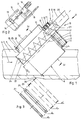
Die Vorrichtung gemäß Figur 1 weist eine zylindermantelförmig ausgebildete Abscheidefläche 1 auf, die als umlaufender Siebkorb ausgebildet sein kann. Die Abscheidefläche 1 ist mit ihrer Achse 2 schrägstehend in einem Winkel von etwa 45° in einem Gerinne 3 angeordnet. Die Breite des Gerinnes 3 entspricht dem Durchmesser der Abscheidefläche 1. Die Abscheidefläche 1 besitzt an ihrem oberen Ende eine geschlossen ausgebildete Stirnfläche 4 und an ihrem unteren Ende eine offene Stirnfläche 5, durch die die mit Abscheidegut beladene Flüssigkeit gemäß Pfeil 6 einströmt.The device according to FIG. 1 has a separating
Im Anschluß an die geschlossene Stirnfläche 4 weist die Abscheidefläche 1 einen Fortsatz 7 auf, der der Lagerung und des Angriffes eines Antriebes 8 dient. Es sind hier Abstützarme 9 und 10 vorgesehen, die an ihren dem Fortsatz 7 zugekehrten Enden Rollen 11 bzw. 12 tragen, auf denen der Fortsatz 7 abrollt. Innerhalb des Fortsatzes 7 ist auch ein Zahnkranz 13 angeordnet, der mit einem Ritzel 14 zusammenarbeitet (Figur 2), welches auf einer Welle 15 sitzt, die von einem Motor 16 mit Getriebe 17 angetrieben wird. Sowohl der Motor 16 mit Getriebe 17, die die wesentlichen Teile des Antriebs 8 bilden, wie auch die Abstützarme 9 und 10 sind auf einem Gehäuse 18 einer Schneckenfördereinrichtung 19 angeordnet und abgestützt.Following the
Die Schneckenfördereinrichtung 19 weist eine Achse 20 auf, die gemäß der Ausführungsform nach Figur 1 parallel zu der Achse 2 der Abscheidefläche 1 nach oben versetzt angeordnet ist. Auch die übrigen Teile der Scheckenfördereinrichtung 19, nämlich eine Welle 21, eine Förderwendel 22 und ein Einwurftrichter 23 mit einer dem Gerinne 3 zugekehrten Stirnwand 24 sind entsprechend versetzt zu der Achse 2 der Abscheidefläche 1 vorgesehen. Die Achse 20 liegt oberhalb einer Ebene durch die Achse 2 senkrecht zur Zeichenebene. Es ist nicht unbedingt erforderlich, daß die Achse 20 senkrecht über der Achse 2 liegt. Wichtig ist, daß die Schneckenfördereinrichtung 19 mit ihrer Achse 20 nach oben versetzt zu der Achse 2 vorgesehen ist. Im Bereich des Einwurftrichters 23 ist die Förderwendel 22 wellenlos angeordnet.The
Die Oberkante der Stirnwand 24 des Einwurftrichters 23 bestimmt die maximale Einstauhöhe und damit auch die Größe der effektiv durchströmbaren und damit nutzbaren Teilfläche der Abscheidefläche 1. Es ist erkennbar, daß die effektiv wirksame Teilfläche in Richtung der Achse 2 von unten nach oben abnimmt. Je höher jedoch die Einstauhöhe gestaltet werden kann, desto größer ist die effektiv nutzbare Teilfläche der Abscheidefläche 1.The upper edge of the
Der obere Teil der Schneckenfördereinrichtung 19 ist in Figur 1 nicht dargestellt. Er kann ähnlich gestaltet sein wie im Stand der Technik. Auch ein gesonderter Antrieb für die Welle 21 und die Förderwendel 22, wie er üblicherweise im freien Endbereich des Gehäuses 18 aufgesetzt ist, ist der Übersichtlichkeit halber nicht dargestellt.The upper part of the
Auch im unteren Bereich der Abscheidefläche 1, also im Bereich der offenen Stirnfläche 5, können Abstützarme 25 mit Rollen 26 angeordnet sein, auf denen die zylindermantelförmige Abscheidefläche 1 abrollt. Die Abstützarme 25 sind an dem Einfülltrichter 23 abgestützt, der in das Gehäuse 18 der Schneckenfördereinrichtung 19 übergeht.
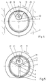
In Figur 3 sind verschiedene Ausführungsmöglichkeiten für eine zylindermantelförmige Abscheidefläche 1 dargestellt. Diese kann aus gebogenen Flachstäben 27, aus keilförmigen Stäben 28, aus Filtermaterial 29 oder aus Filterkeramik 30 bestehen bzw. ausgebildet sein.In Figure 3 are different execution options for a cylindrical jacket-shaped
Figur 4 läßt noch einmal genau erkennen, daß die Achse 20 nicht mehr koaxial zur Achse 2, sondern nach oben in einen halbkreisförmig begrenzten Raum hinein versetzt angeordnet ist. Die Abscheidefläche 1 wird gemäß Pfeil 31 in der einen oder anderen Drehrichtung umlaufend angetrieben, was kontinuierlich oder taktweise geschehen kann. Im oberen Bereich und stillstehend gegenüber der umlaufend angetriebenen Abscheidefläche 1 ist eine Ablöseeinrichtung 32 (Figur 1) vorgesehen. die über die Länge der Abscheidefläche 1 durchgehend vorgesehen ist und aus einer Bürste. einer Düsenleiste. aus Schwenkabstreifern o. dgl. bestehen kann. Die Ablöseeinrichtung 32 ist relativ zu dem Einwurftrichter 23 angeordnet. d. h. wenn die Schneckenfördereinrichtung 18 mit Förderwendel 22 und ihren übrigen Teilen nicht exakt vertikal über der Achse 2 angeordnet ist, sondern beispielsweise seitlich versetzt dem aufsteigenden Trum der Abscheidefläche 1 zugekehrt, dann ist auch die Ablöseeinrichtung 32 entsprechend am äußeren Umfang der Abscheidefläche 1 vorgesehen.FIG. 4 shows again exactly that the
Aus Figur 5 ist die Anordnung der Abstützarme 9 an dem Gehäuse 18 der Schneckenfördereinrichtung mit ihrer Förderwendel 22 erkennbar.The arrangement of the
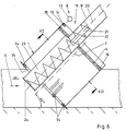
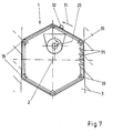
Bei der Ausführungsform gemäß den Figuren 6 und 7 ist die Abscheidefläche 1 als Gliederbandrechen ausgebildet und aus gegeneinander beweglichen Einzelteilen zusammengesetzt. Die Abscheidefläche 1 wird auch hier über den Antrieb 8 angetrieben. Es sind Rollen 33 und 34 angeordnet, so daß die Abscheidefläche 1 in Form eines Sechsecks aufgespannt und geführt wird, wie dies insbesondere aus Figur 7 erkennbar ist. Die Abscheidefläche 1 kann mit Fanghaken 35 versehen sein, die die Aufwärtsförderung des Abscheidegutes an der Innenseite der Abscheidefläche 1 begünstigen. Aus Figur 7 ist auch erkennbar, daß die Achse 20 oberhalb und seitlich der Achse 2 versetzt angeordnet sein kann. Entsprechend ist auch die Ablöseeinrichtung 32 vorgesehen.In the embodiment according to FIGS. 6 and 7, the separating
- 1 -1 -
- AbscheideflächeSeparation area
- 2 -2 -
- Achseaxis
- 3 -3 -
- GerinneFlumes
- 4 -4 -
- StirnflächeFace
- 5 -5 -
- StirnflächeFace
- 6 -6 -
- Pfeilarrow
- 7 -7 -
- FortsatzContinuation
- 8 -8th -
- Antriebdrive
- 9 -9 -
- AbstützarmSupport arm
- 10 -10 -
- AbstützarmSupport arm
- 11 -11 -
- Rollerole
- 12 -12 -
- Rollerole
- 13 -13 -
- ZahnkranzSprocket
- 14 -14 -
- Ritzelpinion
- 15 -15 -
- Wellewave
- 16 -16 -
- Motorengine
- 17 -17 -
- Getriebetransmission
- 18 -18 -
- Gehäusecasing
- 19 -19 -
- SchneckenfördereinrichtungScrew conveyor
- 20 -20 -
- Achseaxis
- 21 -21 -
- Wellewave
- 22 -22 -
- FörderwendelFunding spiral
- 23 -23 -
- EinwurftrichterThrow-in funnel
- 24 -24 -
- StirnwandFront wall
- 25 -25 -
- AbstützarmSupport arm
- 26 -26 -
- Rollerole
- 27 -27 -
- FlachstäbeFlat bars
- 28 -28 -
- StäbeRods
- 29 -29 -
- FiltermaterialFilter material
- 30 -30 -
- FilterkeramikFilter ceramic
- 31 -31 -
- Pfeilarrow
- 32 -32 -
- AblöseeinrichtungDetachment device
- 33 -33 -
- Rollerole
- 34 -34 -
- Rollerole
- 35 -35 -
- FanghakenCatch hook
Claims (10)
Applications Claiming Priority (2)
| Application Number | Priority Date | Filing Date | Title |
|---|---|---|---|
| DE4314673 | 1993-05-04 | ||
| DE4314673A DE4314673C1 (en) | 1993-05-04 | 1993-05-04 | Worm drive axis - is positioned above and at a distance from the axis of the surrounding rotating sepn. surface |
Publications (2)
| Publication Number | Publication Date |
|---|---|
| EP0623712A2 true EP0623712A2 (en) | 1994-11-09 |
| EP0623712A3 EP0623712A3 (en) | 1994-11-23 |
Family
ID=6487115
Family Applications (1)
| Application Number | Title | Priority Date | Filing Date |
|---|---|---|---|
| EP19940106638 Withdrawn EP0623712A3 (en) | 1993-05-04 | 1994-04-28 | Device for removing separable matter from a liquid |
Country Status (4)
| Country | Link |
|---|---|
| EP (1) | EP0623712A3 (en) |
| JP (1) | JPH0776871A (en) |
| CN (1) | CN1095128A (en) |
| DE (1) | DE4314673C1 (en) |
Cited By (1)
| Publication number | Priority date | Publication date | Assignee | Title |
|---|---|---|---|---|
| EP1103666A3 (en) * | 1999-11-23 | 2002-12-18 | NEUHOLD Ges.m.b.H | Apparatus for separating debris from a liquid stream in a gully |
Families Citing this family (8)
| Publication number | Priority date | Publication date | Assignee | Title |
|---|---|---|---|---|
| DE4412124C2 (en) * | 1994-04-08 | 1997-04-30 | Huber Hans Gmbh Maschinen Und | Device for removing material to be separated from liquid flowing in a channel |
| SE511921C2 (en) * | 1997-04-04 | 1999-12-13 | Spirac Engineering Ab | Cutting device |
| GB9906470D0 (en) * | 1999-03-19 | 1999-05-12 | Jones & Attwood Ltd | Sewage screening apparatus |
| JP4392157B2 (en) | 2001-10-26 | 2009-12-24 | パナソニック電工株式会社 | WIRING BOARD SHEET MATERIAL AND ITS MANUFACTURING METHOD, AND MULTILAYER BOARD AND ITS MANUFACTURING METHOD |
| DE10302494B3 (en) * | 2003-01-23 | 2004-09-16 | Hans Huber Ag Maschinen- Und Anlagenbau | Device for removing screenings from liquid flowing in a channel |
| US8695804B2 (en) * | 2007-09-04 | 2014-04-15 | Greystone, Inc. | Sand dewatering device and method |
| JP6220308B2 (en) * | 2014-04-16 | 2017-10-25 | 住友重機械エンバイロメント株式会社 | Dust removal equipment, water treatment equipment, dust removal equipment installation method |
| CN112495038A (en) * | 2020-11-10 | 2021-03-16 | 天长市大发化纤有限公司 | Take solid-liquid separation mechanism's polyester staple fiber production line with solid waste clearance mechanism |
Citations (3)
| Publication number | Priority date | Publication date | Assignee | Title |
|---|---|---|---|---|
| FR2424053A1 (en) * | 1978-04-27 | 1979-11-23 | Lecoeur Roger | Horizontal rotary screening drum to filter flocculated waste water - with screw press continuously removing filter cake from drum interior |
| DE3328700A1 (en) * | 1983-06-01 | 1984-12-06 | Arag Apparatebau, Winterthur | Device for separating out coarse material from a free-flowing medium |
| DE3630755A1 (en) * | 1986-09-10 | 1988-03-24 | Huber Hans Georg | DEVICE FOR THE REMOVAL OF SCREEN AND / OR SCREENED GOODS FROM A LIQUID FLOWING |
-
1993
- 1993-05-04 DE DE4314673A patent/DE4314673C1/en not_active Expired - Fee Related
-
1994
- 1994-04-27 JP JP6090092A patent/JPH0776871A/en not_active Withdrawn
- 1994-04-28 EP EP19940106638 patent/EP0623712A3/en not_active Withdrawn
- 1994-04-29 CN CN94104677A patent/CN1095128A/en active Pending
Patent Citations (3)
| Publication number | Priority date | Publication date | Assignee | Title |
|---|---|---|---|---|
| FR2424053A1 (en) * | 1978-04-27 | 1979-11-23 | Lecoeur Roger | Horizontal rotary screening drum to filter flocculated waste water - with screw press continuously removing filter cake from drum interior |
| DE3328700A1 (en) * | 1983-06-01 | 1984-12-06 | Arag Apparatebau, Winterthur | Device for separating out coarse material from a free-flowing medium |
| DE3630755A1 (en) * | 1986-09-10 | 1988-03-24 | Huber Hans Georg | DEVICE FOR THE REMOVAL OF SCREEN AND / OR SCREENED GOODS FROM A LIQUID FLOWING |
Cited By (1)
| Publication number | Priority date | Publication date | Assignee | Title |
|---|---|---|---|---|
| EP1103666A3 (en) * | 1999-11-23 | 2002-12-18 | NEUHOLD Ges.m.b.H | Apparatus for separating debris from a liquid stream in a gully |
Also Published As
| Publication number | Publication date |
|---|---|
| JPH0776871A (en) | 1995-03-20 |
| DE4314673C1 (en) | 1994-05-19 |
| EP0623712A3 (en) | 1994-11-23 |
| CN1095128A (en) | 1994-11-16 |
Similar Documents
| Publication | Publication Date | Title |
|---|---|---|
| DE2741710C2 (en) | Device for separating solids and liquids from a suspension | |
| DE3420157C1 (en) | Device for removing screenings and / or screenings from liquid flowing in a channel | |
| DE3630755C2 (en) | ||
| EP0040425B1 (en) | Device for removing floating materials and debris from a gully, especially from purification plants | |
| EP0565873B1 (en) | Device for compressing and washing of polluted solid matter, especially in purification plants | |
| DE2930581A1 (en) | CENTRIFUGE FOR SORTING AND SEPARATING SOLIDS | |
| EP0908569B1 (en) | Screening device for sewage in an inlet pipe | |
| DE19524276C2 (en) | Device for removing material to be separated from liquid flowing in a channel | |
| DE3122131C2 (en) | Device for the extraction and dewatering of solids from liquids, in particular from channels in sewage treatment plants | |
| DE4314673C1 (en) | Worm drive axis - is positioned above and at a distance from the axis of the surrounding rotating sepn. surface | |
| DE2225231C3 (en) | Screw press | |
| DE4320678C2 (en) | Device for removing screenings from a feed channel through which a contaminated liquid flows, in particular from sewage treatment plants | |
| DE4412124C2 (en) | Device for removing material to be separated from liquid flowing in a channel | |
| EP0062628B1 (en) | Continuously running dehydration apparatus | |
| DE4213847A1 (en) | Sewage cleaning device for sewage treatment plant - has driven conveyor worm, extending through collection basket and part of inclined conveyor channel | |
| DE2342516A1 (en) | MACHINE FOR PEELING OR A SIMILAR SURFACE TREATMENT OF CORN FRUIT | |
| DE4235903C2 (en) | Device for removing material to be separated from a liquid flowing in a channel | |
| DE4328476A1 (en) | Device for discharging solid components from a fluid | |
| DE4338905C1 (en) | Waste extraction mechanism from liquid in gutter | |
| DE202015001595U1 (en) | Device for filtering liquids | |
| DE2832277C2 (en) | ||
| DE19539882C2 (en) | Device for washing contaminated screenings or screenings, especially in sewage treatment plants | |
| DE4006970A1 (en) | Inclined rotary sieves immersed in waste water flow - discharge separated solids into upwardly directed feed worm | |
| DE3915529A1 (en) | Material-extractor from liq. in trough - has auger with no bearings at bottom or shaft at middle | |
| DE6604382U (en) | THICKENER FOR SOLIDS CONTAINING LIQUIDS |
Legal Events
| Date | Code | Title | Description |
|---|---|---|---|
| PUAI | Public reference made under article 153(3) epc to a published international application that has entered the european phase |
Free format text: ORIGINAL CODE: 0009012 |
|
| PUAL | Search report despatched |
Free format text: ORIGINAL CODE: 0009013 |
|
| AK | Designated contracting states |
Kind code of ref document: A2 Designated state(s): AT BE CH ES FR GB IT LI NL |
|
| AK | Designated contracting states |
Kind code of ref document: A3 Designated state(s): AT BE CH ES FR GB IT LI NL |
|
| RAP1 | Party data changed (applicant data changed or rights of an application transferred) |
Owner name: HANS HUBER GMBH MASCHINEN- UND ANLAGENBAU |
|
| 17P | Request for examination filed |
Effective date: 19941123 |
|
| 17Q | First examination report despatched |
Effective date: 19950124 |
|
| STAA | Information on the status of an ep patent application or granted ep patent |
Free format text: STATUS: THE APPLICATION HAS BEEN WITHDRAWN |
|
| 18W | Application withdrawn |
Withdrawal date: 19951026 |