EP0622191A1 - Wiping device of an intaglio printing machine - Google Patents
Wiping device of an intaglio printing machine Download PDFInfo
- Publication number
- EP0622191A1 EP0622191A1 EP94810162A EP94810162A EP0622191A1 EP 0622191 A1 EP0622191 A1 EP 0622191A1 EP 94810162 A EP94810162 A EP 94810162A EP 94810162 A EP94810162 A EP 94810162A EP 0622191 A1 EP0622191 A1 EP 0622191A1
- Authority
- EP
- European Patent Office
- Prior art keywords
- cylinder
- cleaning
- wiping
- wiping cylinder
- nozzles
- Prior art date
- Legal status (The legal status is an assumption and is not a legal conclusion. Google has not performed a legal analysis and makes no representation as to the accuracy of the status listed.)
- Granted
Links
Images
Classifications
-
- B—PERFORMING OPERATIONS; TRANSPORTING
- B41—PRINTING; LINING MACHINES; TYPEWRITERS; STAMPS
- B41F—PRINTING MACHINES OR PRESSES
- B41F9/00—Rotary intaglio printing presses
- B41F9/06—Details
- B41F9/08—Wiping mechanisms
- B41F9/16—Removing or recovering ink from wiping mechanisms
-
- B—PERFORMING OPERATIONS; TRANSPORTING
- B41—PRINTING; LINING MACHINES; TYPEWRITERS; STAMPS
- B41F—PRINTING MACHINES OR PRESSES
- B41F9/00—Rotary intaglio printing presses
- B41F9/06—Details
- B41F9/08—Wiping mechanisms
- B41F9/10—Doctors, scrapers, or like devices
- B41F9/1018—Doctors, scrapers, or like devices using a wiping cylinder
Definitions
- the present invention relates to a device for wiping a machine for intaglio printing comprising a wiping cylinder and an installation for the continuous cleaning of said cylinder, this installation comprising a container for receiving the cleaning liquid.
- a device for wiping a machine for intaglio printing comprising a wiping cylinder and an installation for the continuous cleaning of said cylinder, this installation comprising a container for receiving the cleaning liquid.
- which acts permanently on the wiping cylinder and cleaning elements in contact with the periphery of the wiping cylinder comprising, in the direction of rotation of this cylinder, a first cleaning element, which removes most of the ink from the wiping cylinder, followed, at defined distances, by several other elements constituted by brushes and / or scrapers, at least one row of nozzles parallel to the axis of the wiping cylinder, the nozzles being arranged for ejecting the cleaning liquid in the region of the region of contact of said first cleaning element with the wiping cylinder.
- doctor blade is quite effective, since it alone removes practically 90% of the ink from the surface of the wiping cylinder, it has been found in use that, due to friction important between the doctor blade and the cylinder, friction which is reinforced by the angle inclination acute scraping with respect to the periphery of the wiping cylinder, the surface of the cylinder undergoes very great wear forces which risk damaging it, all the more so since this surface is made of synthetic material, in particular PVC. In addition, it was found that said doctor blade very quickly becomes sharp, which increases the wear of the wiping cylinder and forces the user to replace this doctor blade about every 24 hours.
- the present invention proposes to overcome the drawbacks inherent in a steel doctor blade by sparing the surface of the wiping cylinder while reducing the cost of maintenance.
- the installation according to the invention is characterized in that the first cleaning element is made of textile material in the form of a strip which is mounted folded back on itself on and along a rigid support, so to overflow from it.
- This textile material is preferably made of porous synthetic fibers.
- a first cleaning element is thus obtained which is as effective as a rigid scraper but which, thanks to its flexibility, does not risk damaging the surface of the wiping cylinder, which therefore increases the life of the latter. Another advantage is that the wear being less than with a steel scraper, the life of the cleaning element itself is longer, of the order of eight days, which is clearly more economical for the user.
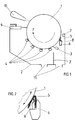
- FIG. 1 represents a schematic view of the device for cleaning the wiping cylinder.
- Figure 2 is an enlarged partial view of the contact area of the first cleaning element with the wiping cylinder.
- the wiping device comprises a wiping cylinder 1, rotating in the direction of arrow F, intended to be in permanent contact with the plate cylinder not shown, the peripheral direction of rotation of this wiping cylinder 1 being opposite to that of the plate cylinder.
- This wiping cylinder 1 is partially arranged inside a container 2 in which the cleaning installation is mounted.
- the surface of the wiping cylinder 1 is made of synthetic material, in particular PVC, which ensures good wiping of the plate cylinder.
- the cleaning installation comprises, in a manner known per se, several cleaning elements constituted, in the example considered, by a doctor blade 3 forming an obtuse angle with the periphery of the cylinder 1 located following this doctor blade direction of rotation of said cylinder, and by brushes 4 arranged at a distance from one another around the periphery of cylinder 1.
- a first cleaning element 5 consisting of a textile material of porous synthetic fibers, with a thickness of between 5 and 20 mm, preferably 10 mm, sold for example by the company 3M under the name "Scotch-Brite" or "hand pad".
- This textile material is in the form of a strip whose dimension in the axial direction of the cylinder corresponds to the length of the latter so that the entire surface is covered, and which is mounted, folded back on itself (FIG. 2), on and along a support 6 so as to protrude therefrom.
- the inclination of the support 6 is adjustable to adjust the contact pressure between the strip of textile material and the surface of the cylinder 1, this support 6 having the same configuration as the doctor blade which, in the previous installations, was intended to carry the steel scraper.
- This element 5 which is fixed in any known manner to the support 6, is intended to apply tangentially over the entire length of the wiping cylinder 1 during the rotation thereof, forming an acute angle with the periphery of the cylinder located after this element in the direction of rotation of the cylinder, and to rub its surface so as to remove approximately 90% of the quantity of ink present on the surface of the wiping cylinder.
- Above the first cleaning element 5 is provided a row of spray nozzles 7 directed just before the contact zone of said element 5 with the cylinder 1.
- nozzles 8 In the support 6 is provided a second row of nozzles 8 whose mouths are directed towards inside the fold formed by the first cleaning element 5. These nozzles 7 and 8 are intended to send under pressure a cleaning liquid which, on the one hand, deterges the ink and, on the other hand, wets and rinses permanently cleaning element 5, which prevents fouling thereof during friction.
- the cleaning liquid from the nozzles 7, 8 and the nozzles associated with the brushes 4 is collected in the container 2 and flows through outlet orifices 11 so that the wiping cylinder 1 is not immersed in the soiled liquid.
- a separation wall 2 ′ in the container 2 makes it possible to separate the cleaning liquid coming from the nozzles 7, 8, which is soiled by the greatest amount of ink from the less dirty liquid coming from the nozzles associated with the brushes 4.
Landscapes
- Engineering & Computer Science (AREA)
- Mechanical Engineering (AREA)
- Inking, Control Or Cleaning Of Printing Machines (AREA)
- Rotary Presses (AREA)
- Screen Printers (AREA)
- Treatment Of Fiber Materials (AREA)
Abstract
Description
La présente invention concerne un dispositif d'essuyage d'une machine pour l'impression en taille-douce comprenant un cylindre d'essuyage et une installation pour le nettoyage en continu dudit cylindre, cette installation comportant un récipient pour la réception du liquide de nettoyage qui agit en permanence sur le cylindre d'essuyage et des éléments de nettoyage au contact de la périphérie du cylindre d'essuyage comprenant, dans le sens de rotation de ce cylindre, un premier élément de nettoyage, qui enlève la plus grande partie de l'encre du cylindre d'essuyage, suivi, à des distances définies, de plusieurs autres éléments constitués par des brosses et/ou des râcles, au moins une rangée de buses parallèle à l'axe du cylindre d'essuyage, les buses étant disposées pour éjecter le liquide de nettoyage dans la zone de la région de contact dudit premier élément de nettoyage avec le cylindre d'essuyage.The present invention relates to a device for wiping a machine for intaglio printing comprising a wiping cylinder and an installation for the continuous cleaning of said cylinder, this installation comprising a container for receiving the cleaning liquid. which acts permanently on the wiping cylinder and cleaning elements in contact with the periphery of the wiping cylinder comprising, in the direction of rotation of this cylinder, a first cleaning element, which removes most of the ink from the wiping cylinder, followed, at defined distances, by several other elements constituted by brushes and / or scrapers, at least one row of nozzles parallel to the axis of the wiping cylinder, the nozzles being arranged for ejecting the cleaning liquid in the region of the region of contact of said first cleaning element with the wiping cylinder.
Selon le brevet suisse No 596 988 de la déposante, on connaît déjà une installation de nettoyage du cylindre d'essuyage dans laquelle le premier élément de nettoyage est constitué par une râcle en acier formant un angle aigu avec la périphérie du cylindre située à la suite de cette râcle dans le sens de rotation du cylindre, et destinée à enlever la plus grande partie de l'encre. Bien que cette râcle soit tout à fait efficace, puisqu'elle permet d'enlever à elle seule pratiquement 90% de l'encre de la surface du cylindre d'essuyage, on a pu constater à l'usage que, du fait du frottement important entre la râcle et le cylindre, frottement qui est renforcé par l'inclinaison à angle aigu de la râcle par rapport à la périphérie du cylindre d'essuyage, la surface du cylindre subit de très grandes forces d'usure qui risquent de l'endommager, d'autant plus que cette surface est en matière synthétique, notamment en PVC. En outre, on a constaté que ladite râcle devient très vite tranchante, ce qui accentue l'usure du cylindre d'essuyage et oblige l'utilisateur à remplacer cette râcle toutes les 24 heures environ.According to Swiss patent No. 596 988 of the applicant, there is already known an installation for cleaning the wiping cylinder in which the first cleaning element is constituted by a steel scraper forming an acute angle with the periphery of the cylinder located after of this doctor blade in the direction of rotation of the cylinder, and intended to remove most of the ink. Although this doctor blade is quite effective, since it alone removes practically 90% of the ink from the surface of the wiping cylinder, it has been found in use that, due to friction important between the doctor blade and the cylinder, friction which is reinforced by the angle inclination acute scraping with respect to the periphery of the wiping cylinder, the surface of the cylinder undergoes very great wear forces which risk damaging it, all the more so since this surface is made of synthetic material, in particular PVC. In addition, it was found that said doctor blade very quickly becomes sharp, which increases the wear of the wiping cylinder and forces the user to replace this doctor blade about every 24 hours.
La présente invention se propose de pallier les inconvénients inhérents à une râcle en acier en ménageant la surface du cylindre d'essuyage tout en diminuant le coût de l'entretien.The present invention proposes to overcome the drawbacks inherent in a steel doctor blade by sparing the surface of the wiping cylinder while reducing the cost of maintenance.
A cet effet, l'installation selon l'invention est caractérisée par le fait que le premier élément de nettoyage est en matière textile sous forme de bande qui est montée repliée sur elle-même sur et le long d'un support rigide, de manière à déborder de celui-ci. Cette matière textile est de préférence en fibres synthétiques poreuses.To this end, the installation according to the invention is characterized in that the first cleaning element is made of textile material in the form of a strip which is mounted folded back on itself on and along a rigid support, so to overflow from it. This textile material is preferably made of porous synthetic fibers.
Jusqu'ici, l'homme du métier était convaincu que pour enlever la plus grande partie de l'encre le premier élément de nettoyage devait obligatoirement être en matériau rigide, solide comme de l'acier, c'est pourquoi la râcle en acier a été considérée comme nécessaire pendant de nombreuses années. Cependant, d'une manière surprenante, on a découvert que le même effet était produit par un élément en simple matière textile en évitant les désavantages de la râcle en acier.Until now, those skilled in the art were convinced that in order to remove most of the ink, the first cleaning element had to be made of rigid material, solid like steel, which is why the steel scraper was been considered necessary for many years. However, surprisingly, it has been discovered that the same effect is produced by a simple textile element while avoiding the disadvantages of the steel scraper.
On obtient ainsi un premier élément de nettoyage aussi efficace qu'une râcle rigide mais qui, grâce à sa souplesse, ne risque pas de détériorer la surface du cylindre d'essuyage, donc qui permet d'augmenter la durée de vie de celui-ci. Un autre avantage est que l'usure étant moindre qu'avec une râcle en acier, la durée de vie de l'élément de nettoyage lui-même est plus longue, de l'ordre de huit jours, ce qui est nettement plus économique pour l'utilisateur.A first cleaning element is thus obtained which is as effective as a rigid scraper but which, thanks to its flexibility, does not risk damaging the surface of the wiping cylinder, which therefore increases the life of the latter. Another advantage is that the wear being less than with a steel scraper, the life of the cleaning element itself is longer, of the order of eight days, which is clearly more economical for the user.
Le dessin annexé représente, à titre d'exemple, une forme d'éxécution de l'invention.The accompanying drawing shows, by way of example, an embodiment of the invention.
La figure 1 représente une vue schématique du dispositif de nettoyage du cylindre d'essuyage.FIG. 1 represents a schematic view of the device for cleaning the wiping cylinder.
La figure 2 est une vue partielle agrandie de la zone de contact du premier élément de nettoyage avec le cylindre d'essuyage.Figure 2 is an enlarged partial view of the contact area of the first cleaning element with the wiping cylinder.
Le dispositif d'essuyage comporte un cylindre d'essuyage 1, tournant dans le sens de la flèche F, destiné à être en contact permanent avec le cylindre porte-plaques non représenté, le sens de rotation périphérique de ce cylindre d'essuyage 1 étant opposé à celui du cylindre porte-plaques. Ce cylindre d'essuyage 1 est disposé partiellement à l'intérieur d'un récipient 2 dans lequel est montée l'installation de nettoyage. La surface du cylindre d'essuyage 1 est en matériau synthétique, notamment en PVC, ce qui assure un bon essuyage du cylindre porte-plaques.The wiping device comprises a
L'installation de nettoyage comporte, d'une manière connue en soi, plusieurs éléments de nettoyage constitués, dans l'exemple considéré, par une râcle 3 formant un angle obtus avec la périphérie du cylindre 1 située à la suite de cette râcle dans le sens de rotation dudit cylindre, et par des brosses 4 disposées à distance les une des autres autour de la périphérie du cylindre 1.The cleaning installation comprises, in a manner known per se, several cleaning elements constituted, in the example considered, by a
Ces brosses 4, et le cas échéant la râcle 3, sont montées dans le récipient 2 sur un rail commun permettant de les approcher ou de les éloigner simultanément de la surface du cylindre d'essuyage 1. Des buses de giclage d'un liquide de nettoyage, non représentées, sont associées à chacune de ces brosses 4 de telle manière que la région du cylindre 1 située avant la zone de contact de chaque élément de nettoyage soit mouillée.These
Avant les brosses 4 et la râcle 3, dans le sens de rotation du cylindre d'essuyage 1, est monté un premier élément de nettoyage 5 constitué par une matière textile de fibres synthétiques poreuses, d'une épaisseur comprise entre 5 et 20 mm, de préférence 10 mm, commercialisée par exemple par la société 3M sous le nom "Scotch-Brite" ou "tampon à main". Cette matière textile est sous forme d'une bande dont la dimension dans le sens axial du cylindre correspond à la longueur de celui-ci pour que toute la surface soit couverte, et qui est montée, repliée sur elle-même (figure 2), sur et le long d'un support 6 de manière à dépasser de celui-ci. L'inclinaison du support 6 est ajustable pour régler la pression de contact entre la bande de matière textile et la surface du cylindre 1, ce support 6 étant de même configuration que le porte-râcle qui, dans les installations précédentes, était destiné à porter la râcle en acier. Cet élément 5 qui est fixé de n'importe quelle manière connue sur le support 6, est prévu pour s'appliquer tangentiellement sur toute la longueur du cylindre d'essuyage 1 lors de la rotation de celui-ci, en formant un angle aigu avec la périphérie du cylindre située à la suite de cet élément dans le sens de rotation du cylindre, et pour frotter sa surface de manière à enlever environ 90% de la quantité d'encre présente à la surface du cylindre d'essuyage. Au dessus du premier élément de nettoyage 5 est prévue une rangée de buses de giclage 7 dirigées juste avant la zone de contact dudit élément 5 avec le cylindre 1. Dans le support 6 est prévue une deuxième rangée de buses 8 dont les bouches sont dirigées vers l'intérieur du pli formé par le premier élément de nettoyage 5. Ces buses 7 et 8 sont destinées à envoyer sous pression un liquide de nettoyage qui, d'une part, déterge l'encre et, d'autre part, mouille et rince en permanence l'élément de nettoyage 5, ce qui évite l'encrassement de celui-ci lors du frottement.Before the
Le liquide de nettoyage provenant des buses 7, 8 et des buses associées aux brosses 4 est récolté dans le récipient 2 et s'écoule à travers des orifices de sortie 11 de manière que le cylindre d'essuyage 1 ne se trouve pas immergé dans le liquide souillé. Une paroi de séparation 2' dans le récipient 2 permet de séparer le liquide de nettoyage provenant des buses 7, 8, qui est souillé par la plus grande quantité d'encre du liquide moins sale provenant des buses associées aux brosses 4.The cleaning liquid from the
Les résidus d'encre à la surface du cylindre d'essuyage 1 sont enlevés grâce à l'action de la râcle 3 pour diminuer la contamination des brosses et le nettoyage complet est achevé par les brosses 4, en combinaison avec le liquide de nettoyage éjecté par les buses qui leur sont associées. Enfin, après les brosses 4, est prévue une lame rigide 9, notamment en acier, qui essuie le cylindre et le sèche partiellement, et le séchage complet est réalisé par l'action d'une soufflerie d'air 10. Ainsi, la surface du cylindre d'essuyage 1 qui va entrer à nouveau en contact avec le cylindre porte-plaque est nette de toute trace d'encre et prête à jouer son rôle d'essuyage.The ink residue on the surface of the
Claims (5)
Applications Claiming Priority (2)
| Application Number | Priority Date | Filing Date | Title |
|---|---|---|---|
| CH1318/93 | 1993-04-30 | ||
| CH131893 | 1993-04-30 |
Publications (2)
| Publication Number | Publication Date |
|---|---|
| EP0622191A1 true EP0622191A1 (en) | 1994-11-02 |
| EP0622191B1 EP0622191B1 (en) | 1997-01-22 |
Family
ID=4207639
Family Applications (1)
| Application Number | Title | Priority Date | Filing Date |
|---|---|---|---|
| EP94810162A Expired - Lifetime EP0622191B1 (en) | 1993-04-30 | 1994-03-16 | Wiping device of an intaglio printing machine |
Country Status (10)
| Country | Link |
|---|---|
| US (1) | US5390598A (en) |
| EP (1) | EP0622191B1 (en) |
| JP (1) | JP3469303B2 (en) |
| KR (1) | KR100330114B1 (en) |
| CN (1) | CN1036641C (en) |
| AT (1) | ATE148032T1 (en) |
| AU (1) | AU664965B2 (en) |
| CA (1) | CA2119628A1 (en) |
| DE (1) | DE69401525T2 (en) |
| RU (1) | RU2119432C1 (en) |
Cited By (4)
| Publication number | Priority date | Publication date | Assignee | Title |
|---|---|---|---|---|
| EP1055516A1 (en) * | 1999-05-25 | 2000-11-29 | Komori Corporation | Wiping device of intaglio printing press |
| EP1790473A1 (en) | 2005-11-25 | 2007-05-30 | Kba-Giori S.A. | Method for detection of occurrence of printing errors on printed substrates during processing thereof on a printing press |
| WO2007085862A1 (en) * | 2006-01-30 | 2007-08-02 | De La Rue International Limited | Intaglio plate wiping system |
| US8613254B2 (en) | 2005-11-25 | 2013-12-24 | Kba-Notasys Sa | Method for detection of occurrence of printing errors on printed substrates during processing thereof on a printing press |
Families Citing this family (20)
| Publication number | Priority date | Publication date | Assignee | Title |
|---|---|---|---|---|
| JP3234101B2 (en) * | 1994-05-09 | 2001-12-04 | 株式会社リコー | Apparatus for removing film-like image forming substances from recording materials |
| US5575211A (en) * | 1994-10-28 | 1996-11-19 | Hycorr Machine Corporation | Washing Arrangement for rotary printer |
| UA28061C2 (en) * | 1996-09-02 | 2000-10-16 | Де Ля Рю Жіорі С.А. | method and device for obtaining FRESH washing solution and treating spent solution |
| IT1297042B1 (en) * | 1997-12-31 | 1999-08-03 | De La Rue Giori Sa | PROCESS OF PRODUCTION OF FRESH DRYING SOLUTION AND TREATMENT OF USED DRYING SOLUTION AND DEVICE OF |
| US6196126B1 (en) | 1999-01-12 | 2001-03-06 | Intex Corporation | Method and apparatus for preventing pigment buildup during a rotary screen printing process |
| EP1361046A1 (en) | 2002-05-06 | 2003-11-12 | Kba-Giori S.A. | Nozzles for a cleaning installation of a printing machine |
| JP4706059B2 (en) * | 2005-07-20 | 2011-06-22 | 独立行政法人 国立印刷局 | Wiping automatic cleaning device |
| EP1764216A1 (en) * | 2005-09-16 | 2007-03-21 | Kba-Giori S.A. | Apparatus for coating a cylinder, in particular a wiping cylinder of an intaglio printing press |
| KR100667882B1 (en) * | 2005-10-04 | 2007-01-11 | 주식회사 디엠에스 | Apparatus for making color-filter layer on substrate |
| EP1844930A1 (en) | 2006-04-11 | 2007-10-17 | Kba-Giori S.A. | Ink wiping system for a printing machine |
| WO2009015144A1 (en) * | 2007-07-25 | 2009-01-29 | Air Motion Systems, Inc. | Printing cylinder cleaning system |
| KR100887387B1 (en) * | 2007-08-24 | 2009-03-06 | 삼성전기주식회사 | Apparatus and method for manufacturing printed circuit board |
| JP2013056541A (en) * | 2011-08-15 | 2013-03-28 | Komori Corp | Wiping device |
| CN103302968B (en) * | 2013-06-25 | 2016-02-24 | 北京印钞有限公司 | Intaglio printing press wipes ink roller cleaning method and device |
| CN103738054B (en) * | 2013-12-20 | 2016-08-17 | 深圳劲嘉集团股份有限公司 | A kind of automatic plate cleaning device of intaglio press and implementation method |
| CN106379052B (en) * | 2016-11-17 | 2018-01-19 | 重庆强大巴郡知识产权服务有限公司 | Ceramic tile printing device |
| JP2018106063A (en) * | 2016-12-27 | 2018-07-05 | エスプリンティンソリューション株式会社 | Image formation apparatus |
| CN108248208A (en) * | 2018-01-30 | 2018-07-06 | 海宁美力针织有限公司 | A kind of slip cover production dyeing and printing device |
| CN113524903A (en) * | 2021-07-14 | 2021-10-22 | 山东锦龙包装有限公司 | Food package bag color printing pigment scraping device |
| CN113771489B (en) * | 2021-07-29 | 2023-04-28 | 阜阳市新世纪包装彩印有限公司 | Printing head with dry ink scraping mechanism for wine box printing |
Citations (3)
| Publication number | Priority date | Publication date | Assignee | Title |
|---|---|---|---|---|
| FR1517914A (en) * | 1967-02-06 | 1968-03-22 | Method for cleaning the wiping cylinder in cylinder machines for intaglio printing and device for implementing said method | |
| CH596988A5 (en) * | 1976-09-17 | 1978-03-31 | De La Rue Giori Sa | |
| EP0514756A1 (en) * | 1991-05-22 | 1992-11-25 | Komori Corporation | Wiping apparatus of intaglio printing press |
Family Cites Families (5)
| Publication number | Priority date | Publication date | Assignee | Title |
|---|---|---|---|---|
| US4135448A (en) * | 1974-09-11 | 1979-01-23 | Moestue Hans J | Mechanism for cleaning a cylinder of an offset lithographic printing press |
| JPS58101060A (en) * | 1981-12-12 | 1983-06-16 | Komori Printing Mach Co Ltd | Wiping device for intaglio printing machine |
| JPH02215533A (en) * | 1989-02-17 | 1990-08-28 | B J Trading Kk | Method of cleansing ink feed roller of printing press and apparatus therefor |
| CH681875A5 (en) * | 1990-08-17 | 1993-06-15 | De La Rue Giori Sa | |
| AU648486B2 (en) * | 1991-10-17 | 1994-04-21 | De La Rue Giori S.A. | Wiping device of an intaglio printing machine |
-
1994
- 1994-03-16 EP EP94810162A patent/EP0622191B1/en not_active Expired - Lifetime
- 1994-03-16 DE DE69401525T patent/DE69401525T2/en not_active Expired - Fee Related
- 1994-03-16 AT AT94810162T patent/ATE148032T1/en not_active IP Right Cessation
- 1994-03-22 AU AU57929/94A patent/AU664965B2/en not_active Ceased
- 1994-03-22 CA CA002119628A patent/CA2119628A1/en not_active Abandoned
- 1994-03-25 US US08/217,976 patent/US5390598A/en not_active Expired - Fee Related
- 1994-04-01 JP JP06490294A patent/JP3469303B2/en not_active Expired - Fee Related
- 1994-04-19 CN CN94104035A patent/CN1036641C/en not_active Expired - Fee Related
- 1994-04-29 RU RU94015234A patent/RU2119432C1/en active
- 1994-04-30 KR KR1019940009406A patent/KR100330114B1/en not_active IP Right Cessation
Patent Citations (3)
| Publication number | Priority date | Publication date | Assignee | Title |
|---|---|---|---|---|
| FR1517914A (en) * | 1967-02-06 | 1968-03-22 | Method for cleaning the wiping cylinder in cylinder machines for intaglio printing and device for implementing said method | |
| CH596988A5 (en) * | 1976-09-17 | 1978-03-31 | De La Rue Giori Sa | |
| EP0514756A1 (en) * | 1991-05-22 | 1992-11-25 | Komori Corporation | Wiping apparatus of intaglio printing press |
Cited By (6)
| Publication number | Priority date | Publication date | Assignee | Title |
|---|---|---|---|---|
| EP1055516A1 (en) * | 1999-05-25 | 2000-11-29 | Komori Corporation | Wiping device of intaglio printing press |
| US6341556B1 (en) | 1999-05-25 | 2002-01-29 | Komori Corporation | Wiping device of intaglio printing press |
| EP1790473A1 (en) | 2005-11-25 | 2007-05-30 | Kba-Giori S.A. | Method for detection of occurrence of printing errors on printed substrates during processing thereof on a printing press |
| US8613254B2 (en) | 2005-11-25 | 2013-12-24 | Kba-Notasys Sa | Method for detection of occurrence of printing errors on printed substrates during processing thereof on a printing press |
| WO2007085862A1 (en) * | 2006-01-30 | 2007-08-02 | De La Rue International Limited | Intaglio plate wiping system |
| EA013550B1 (en) * | 2006-01-30 | 2010-06-30 | Де Ля Рю Интернэшнл Лимитед | Intaglio plate wiping system |
Also Published As
| Publication number | Publication date |
|---|---|
| CN1116162A (en) | 1996-02-07 |
| JP3469303B2 (en) | 2003-11-25 |
| EP0622191B1 (en) | 1997-01-22 |
| CA2119628A1 (en) | 1994-10-31 |
| AU5792994A (en) | 1994-11-03 |
| RU2119432C1 (en) | 1998-09-27 |
| DE69401525D1 (en) | 1997-03-06 |
| US5390598A (en) | 1995-02-21 |
| JPH06312501A (en) | 1994-11-08 |
| AU664965B2 (en) | 1995-12-07 |
| DE69401525T2 (en) | 1997-07-31 |
| ATE148032T1 (en) | 1997-02-15 |
| KR100330114B1 (en) | 2002-07-27 |
| CN1036641C (en) | 1997-12-10 |
Similar Documents
| Publication | Publication Date | Title |
|---|---|---|
| EP0622191B1 (en) | Wiping device of an intaglio printing machine | |
| EP0511883B1 (en) | Screen printing method and device for printing a decorative layer on glass sheets | |
| CH624046A5 (en) | ||
| FR2467694A1 (en) | INKING MECHANISM, PARTICULARLY FOR COLOR PRINTING ON BOTTLES OR OTHER CYLINDRICAL OR CONICAL OBJECTS | |
| FR2600026A1 (en) | Spray nozzle for equipping motor vehicle windscreen wipers | |
| EP0889784B1 (en) | Doctor blade for a screen printing machine | |
| EP1762390A1 (en) | Installation for ink replacement in a flexographic printing unit | |
| FR2513953A1 (en) | WIPER BLADE, ESPECIALLY FOR MOTOR VEHICLES | |
| BE523004A (en) | ||
| FR2749247A1 (en) | MOTOR VEHICLE WIPER COMPRISING AN AUTOMATIC CONNECTION FOR A WASHING LIQUID PROJECTION DEVICE | |
| BE550824A (en) | ||
| JPH06102386B2 (en) | Inkjet recording device | |
| EP3056395B1 (en) | Windscreen-wiper blade for a glass panel of a vehicle with adapted nozzle density | |
| EP0550326B1 (en) | Device for uniformly moistening pre-glued labels | |
| BE656481A (en) | ||
| FR2528360A1 (en) | COATING APPARATUS, IN PARTICULAR FOR THE APPLICATION OF HIGH VISCOSITY INKS | |
| FR2767498A1 (en) | Treatment procedure and apparatus for at least one pair of printing rollers | |
| FR2701894A1 (en) | Disposable liners for cleaning printing presses. | |
| WO2022029535A1 (en) | Device for dispensing paper towels | |
| FR2495059A1 (en) | Cleaner for printing machine rollers - has high pressure water jets penetrating covering and spinning it at high speed | |
| FR2760660A1 (en) | Cleaning device for printing transfer support | |
| FI98050C (en) | The filter device | |
| FR2754686A1 (en) | NAIL VARNISH APPLICATOR ASSEMBLY | |
| FR2580955A1 (en) | CENTRIFUGAL WRINKLER BASKET FOR WET GRANULAR MATERIAL | |
| FR2767497A1 (en) | Printing roller treatment procedure |
Legal Events
| Date | Code | Title | Description |
|---|---|---|---|
| PUAI | Public reference made under article 153(3) epc to a published international application that has entered the european phase |
Free format text: ORIGINAL CODE: 0009012 |
|
| AK | Designated contracting states |
Kind code of ref document: A1 Designated state(s): AT CH DE FR GB IT LI SE |
|
| 17P | Request for examination filed |
Effective date: 19950325 |
|
| GRAG | Despatch of communication of intention to grant |
Free format text: ORIGINAL CODE: EPIDOS AGRA |
|
| 17Q | First examination report despatched |
Effective date: 19960311 |
|
| GRAH | Despatch of communication of intention to grant a patent |
Free format text: ORIGINAL CODE: EPIDOS IGRA |
|
| GRAH | Despatch of communication of intention to grant a patent |
Free format text: ORIGINAL CODE: EPIDOS IGRA |
|
| GRAA | (expected) grant |
Free format text: ORIGINAL CODE: 0009210 |
|
| AK | Designated contracting states |
Kind code of ref document: B1 Designated state(s): AT CH DE FR GB IT LI SE |
|
| REF | Corresponds to: |
Ref document number: 148032 Country of ref document: AT Date of ref document: 19970215 Kind code of ref document: T |
|
| REG | Reference to a national code |
Ref country code: CH Ref legal event code: EP |
|
| ITF | It: translation for a ep patent filed |
Owner name: BUGNION S.P.A. |
|
| REF | Corresponds to: |
Ref document number: 69401525 Country of ref document: DE Date of ref document: 19970306 |
|
| GBT | Gb: translation of ep patent filed (gb section 77(6)(a)/1977) |
Effective date: 19970415 |
|
| PLBE | No opposition filed within time limit |
Free format text: ORIGINAL CODE: 0009261 |
|
| STAA | Information on the status of an ep patent application or granted ep patent |
Free format text: STATUS: NO OPPOSITION FILED WITHIN TIME LIMIT |
|
| 26N | No opposition filed | ||
| PGFP | Annual fee paid to national office [announced via postgrant information from national office to epo] |
Ref country code: DE Payment date: 20000314 Year of fee payment: 7 |
|
| PGFP | Annual fee paid to national office [announced via postgrant information from national office to epo] |
Ref country code: GB Payment date: 20000315 Year of fee payment: 7 |
|
| PGFP | Annual fee paid to national office [announced via postgrant information from national office to epo] |
Ref country code: FR Payment date: 20000316 Year of fee payment: 7 |
|
| PGFP | Annual fee paid to national office [announced via postgrant information from national office to epo] |
Ref country code: SE Payment date: 20000317 Year of fee payment: 7 |
|
| PGFP | Annual fee paid to national office [announced via postgrant information from national office to epo] |
Ref country code: AT Payment date: 20000327 Year of fee payment: 7 |
|
| PGFP | Annual fee paid to national office [announced via postgrant information from national office to epo] |
Ref country code: CH Payment date: 20000428 Year of fee payment: 7 |
|
| PG25 | Lapsed in a contracting state [announced via postgrant information from national office to epo] |
Ref country code: GB Free format text: LAPSE BECAUSE OF NON-PAYMENT OF DUE FEES Effective date: 20010316 Ref country code: AT Free format text: LAPSE BECAUSE OF NON-PAYMENT OF DUE FEES Effective date: 20010316 |
|
| PG25 | Lapsed in a contracting state [announced via postgrant information from national office to epo] |
Ref country code: SE Free format text: LAPSE BECAUSE OF NON-PAYMENT OF DUE FEES Effective date: 20010317 |
|
| PG25 | Lapsed in a contracting state [announced via postgrant information from national office to epo] |
Ref country code: LI Free format text: LAPSE BECAUSE OF NON-PAYMENT OF DUE FEES Effective date: 20010331 Ref country code: CH Free format text: LAPSE BECAUSE OF NON-PAYMENT OF DUE FEES Effective date: 20010331 |
|
| EUG | Se: european patent has lapsed |
Ref document number: 94810162.1 |
|
| GBPC | Gb: european patent ceased through non-payment of renewal fee |
Effective date: 20010316 |
|
| REG | Reference to a national code |
Ref country code: CH Ref legal event code: PL |
|
| PG25 | Lapsed in a contracting state [announced via postgrant information from national office to epo] |
Ref country code: FR Free format text: LAPSE BECAUSE OF NON-PAYMENT OF DUE FEES Effective date: 20011130 |
|
| REG | Reference to a national code |
Ref country code: FR Ref legal event code: ST |
|
| PG25 | Lapsed in a contracting state [announced via postgrant information from national office to epo] |
Ref country code: DE Free format text: LAPSE BECAUSE OF NON-PAYMENT OF DUE FEES Effective date: 20020101 |
|
| PG25 | Lapsed in a contracting state [announced via postgrant information from national office to epo] |
Ref country code: IT Free format text: LAPSE BECAUSE OF NON-PAYMENT OF DUE FEES;WARNING: LAPSES OF ITALIAN PATENTS WITH EFFECTIVE DATE BEFORE 2007 MAY HAVE OCCURRED AT ANY TIME BEFORE 2007. THE CORRECT EFFECTIVE DATE MAY BE DIFFERENT FROM THE ONE RECORDED. Effective date: 20050316 |