EP0621054B1 - Electrode device - Google Patents
Electrode device Download PDFInfo
- Publication number
- EP0621054B1 EP0621054B1 EP94103706A EP94103706A EP0621054B1 EP 0621054 B1 EP0621054 B1 EP 0621054B1 EP 94103706 A EP94103706 A EP 94103706A EP 94103706 A EP94103706 A EP 94103706A EP 0621054 B1 EP0621054 B1 EP 0621054B1
- Authority
- EP
- European Patent Office
- Prior art keywords
- electrode
- electrode device
- gel
- contact
- electrically conductive
- Prior art date
- Legal status (The legal status is an assumption and is not a legal conclusion. Google has not performed a legal analysis and makes no representation as to the accuracy of the status listed.)
- Expired - Lifetime
Links
Images

Classifications
-
- A—HUMAN NECESSITIES
- A61—MEDICAL OR VETERINARY SCIENCE; HYGIENE
- A61N—ELECTROTHERAPY; MAGNETOTHERAPY; RADIATION THERAPY; ULTRASOUND THERAPY
- A61N1/00—Electrotherapy; Circuits therefor
- A61N1/02—Details
- A61N1/04—Electrodes
- A61N1/05—Electrodes for implantation or insertion into the body, e.g. heart electrode
-
- H—ELECTRICITY
- H01—ELECTRIC ELEMENTS
- H01B—CABLES; CONDUCTORS; INSULATORS; SELECTION OF MATERIALS FOR THEIR CONDUCTIVE, INSULATING OR DIELECTRIC PROPERTIES
- H01B1/00—Conductors or conductive bodies characterised by the conductive materials; Selection of materials as conductors
- H01B1/20—Conductive material dispersed in non-conductive organic material
- H01B1/22—Conductive material dispersed in non-conductive organic material the conductive material comprising metals or alloys
-
- H—ELECTRICITY
- H01—ELECTRIC ELEMENTS
- H01B—CABLES; CONDUCTORS; INSULATORS; SELECTION OF MATERIALS FOR THEIR CONDUCTIVE, INSULATING OR DIELECTRIC PROPERTIES
- H01B1/00—Conductors or conductive bodies characterised by the conductive materials; Selection of materials as conductors
- H01B1/20—Conductive material dispersed in non-conductive organic material
- H01B1/24—Conductive material dispersed in non-conductive organic material the conductive material comprising carbon-silicon compounds, carbon or silicon
Definitions
- This invention relates to an electrode device comprising an insulating sleeve in which an electrical conductor is arranged to electrically connect a contact at a proximal part of the electrode device to an electrode surface on the electrode device.
- Electrode devices are used when e.g. a pacemaker or a defibrillator is to be connected to a heart to sense the heart's function or treat the heart.
- these electrode devices are composed of one or more helically wound metal wires running from a contact at a proximal end, connectable to the pacemaker or defibrillator, to an electrode surface connected to or near the heart.
- Such an electrode device is, for example, disclosed in DE-A-3 640 033.
- the electrode surface can e.g. consist of a small pace electrode, a larger intracardiac defibrillation electrode or an epicardiac patch electrode.
- the electrode devices can also be equipped with different kinds of sensors which are connected, via a metal conductor, to the pacemaker or defibrillator.
- Electrodes connected to or near the heart are constantly exposed to changes in load. So one or more of the metal wires could fracture, thereby breaking the electrical connection between an electrode surface or a sensor and the contact at the proximal end.
- the insulation could sustain abrasion damage caused by the constantly shifting load, causing a short-circuit.
- fabrication of the electrode device becomes more complex as the number of incorporated components increases, as when a plurality of electrode surfaces and sensors have to be connected to one and the same electrode device.
- One object of the invention is to achieve an electrode device, according to the introduction above, which is capable of reliably and safely connecting the contact and electrode surfaces electrically, or interconnecting sensors, without the risk of fractures, short-circuits or the like and which is implantable.
- Another object of the invention is to achieve an electrode device for which the number of components can be reduced without any reduction in the number of functions the electrode device can perform.
- a fluid conductor is a completely reliable carrier of energy and signals between the contact and electrode surface or a sensor.
- a fluid conductor can withstand an infinite number of load changes without any break occurring, and a thin layer of insulation is sufficient to prevent short-circuits, since a fluid conductor would impose lighter abrasion loads on the insulation than a solid conductor.
- the fluid conductor can advantageously be non-metallic.
- a refinement of the electrode device is achieved in accordance with the invention in that the insulating sleeve is devised with a through hole between the contact and the electrode surface, and the through hole is filled with an electrically conductive gel to form the electrical conductor.
- Fabrication of the electrode device is simpler, because the through hole in the sleeve only needs to be filled with the fluid gel.
- the distal end comprises a first conductive elastic plate and a second elastic plate joined at the edges, thereby forming a cavity between the plates, said cavity being filled with an electrically conductive gel, and the conductive electrical plate and the electrically conductive gel are electrically connected to the electrical conductor, the conductive plate then forming the electrode surface.
- the electrically conductive gel consists of a doped polymer gel or a hydrophilic gel.
- the gel can particularly be doped with a metallic powder, salt or powdered carbon
- the electrode device can be devised in accordance with the invention in such a way that the insulating sleeve has a through hole between the contact and the electrode surface, and the through hole is filled with an electrolyte.
- an electrolyte would be especially appropriate for use in sensing functions.
- the through hole When the device is implanted in the body, the through hole will fill with body fluid which diffuses in through the sleeve. The undissolved ions deposited in the hole prior to the implantation will then form a solution with the fluid, thereby achieving an electrolyte in the hole. This process occurs within a short time after implantation and is generally completed within a few days.
- the electrode surface can be made of an ion-transporting material.
- the electrode surface is made from an ion-transporting material, no undissolved ions will be needed during fabrication.
- the electrolyte is formed in the through hole by the migration of ions through the ion-transporting material.
- a refinement of the electrode device is achieved in accordance with the invention in that the electrode device further comprises at least one additional electrical conductor to connect at least one additional contact at the proximal end to at least one additional electrode surface.
- the electrode device can encompass an unlimited number of conductors. They can even be a mixture of solid, metal conductors and fluid conductors. When e.g. large energies have to be transferred, as in emission of defibrillation pulses, an arrangement of solid, metal conductors, or a combination of solid, metal conductors and fluid conductors might be appropriate.
- the electrode device could also be devised so it only contains fluid conductors.
- the electrode device so it comprises an insulating sleeve with an electrical conductor to electrically connect a contact at a proximal end of the electrode device with an electrode surface on the electrode device, wherein the electrode device at the distal end comprises a first conductive elastic plate and a second elastic plate joined at the edges, thereby forming a cavity between the plates, said cavity being filled with an electrically conductive gel, and the conductive elastic plate and the electrically conductive gel are electrically connected to the electrical conductor, the conductive plate then forming the electrode surface.
- FIG. 1 a pacemaker 2 connected to a heart 4 by an electrode device 6.
- the electrode device 6 is a VVI device, i.e. it has a tip electrode 8 placed in the right ventricle to stimulate the heart 4 and a ring electrode 10 to sense heart signals in the ventricle.
- the electrode device 6 also has a contact appliance 12 for detachable connection to the pacemaker 2.
- the contact appliance 12 has a first contact surface 14 connected to the tip electrode 8 and pace electronics and a second contact surface 16 connected to the ring electrode 10 and pace electronics.
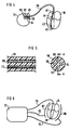
- FIG. 2 a section of the electrode device 6.
- a metal conductor 20 is helically arranged in an insulating sleeve 18.
- the metal conductor 20 has a coating of insulation 22 to insulate the metal conductor from the electrolyte 24 which fills the through hole in the insulating sleeve 18.
- the ring electrode 10 is an integral part of the insulating sleeve 18.
- the ring electrode 10 can be e.g. a platinum electrode, or a membrane made of a conductive material, in contact with the electrolyte 24 and surrounding body tissue in order to receive and transmit electrical signals to the pacemaker.
- FIG. 3 is shown an alternative version of the electrode device 6.
- a first insulating sleeve 26 encloses the entire electrode device 6.
- An insulating tube 30 is located inside this sleeve 26.
- a first fluid conductor 28 is located in the space between the tube 30 and the sleeve 26.
- the fluid conductor 28 can consist of an electrolyte or a conductive gel.
- a second fluid conductor 32 is located in the insulating tube 30 for connection of the tip electrode 8 to the pacemaker 2.
- the second fluid conductor 32 consists of a conductive gel, e.g. a doped polymer gel.
- the ring conductor 10 can be a metal ring or a membrane made from some conductive material.
- FIG. 4 a second embodiment of the electrode device according to the invention.
- a pacemaker 34 is connected to a heart 36 by an electrode device 38.
- the electrode device 38 is devised as a VDD electrode, i.e. it comprises a tip electrode 40 placed in the right ventricle to stimulate heart tissue, a first ring electrode 42 for sensing heart signals in the ventricle and a second ring electrode 44 and a third ring electrode 46 for sensing atrial activity in the heart.
- the electrode device 38 is detachably connected to the pacemaker by a contact appliance 48.
- the contact appliance 48 has a first contact surface 50 which is connected to the tip electrode 40, a second contact surface 52 connected to the first ring electrode 42, a third contact surface 54 connected to the second ring electrode 44 and a fourth contact surface 56 connected to the third ring electrode 46.
- FIG. 5 is shown, to the right, a cross-section of the electrode device 38 and, to the left, a part of a longitudinal cross-section of the electrode device 38.
- the electrode device 38 comprises an insulating sleeve 58 in which four through holes 60, 62, 64, 66 are arranged. Each hole 60, 62, 64, 66 connects the respective tip electrode 40, the first ring electrode 42, the second ring electrode 44 and the third ring electrode 46 (FIG. 4) to the pacemaker 34.
- the first cavity 60, connecting the tip electrode 40 to the first contact surface 50, is filled with an electrically conductive gel 68.
- the other cavities 62, 64, 66 can be filled with a conductive gel or an electrolyte.
- a defibrillator 72 connected to a heart via a first electrode device 76 which has a tip electrode 78 connected to the right ventricle of the heart 74.
- the defibrillator 72 can, via the first electrode device 76, supply the heart with the same treatment as a pacemaker.
- the first electrode device 76 only has one electrical conductor from the defibrillator 72 to the tip electrode 78. This electrical conductor can be devised with an electrically conductive gel in any of the previously described ways.
- the defibrillator 72 comprises a second electrode device 80 and a third electrode device 84.
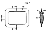
- the second electrode device 80 has a first defibrillation electrode 82 designed to be placed directly on or near the heart 74.
- the third electrode device 84 has a second defibrillation electrode 86 which, in the corresponding way as the first defibrillation electrode 82, is placed directly on or near the heart 74.
- a defibrillation pulse from the defibrillator 72 is delivered across the first defibrillation electrode 82 and the second defibrillation electrode 86 so the pulse passes through the heart 74.
- the second electrode device 80 and the third electrode device 84 can have metallic or non-metallic fluid conductors.
- the first defibrillation electrode 82 has a first electrode plate 88, made from a conductive material, and a second electrode plate 90, which can be conductive or insulating.
- the two plates 88, 90 are joined at the edges, thereby forming a cavity which is filled with an electrically conductive gel 92.
- the first defibrillation electrode 82 is applied to the heart 74 with the conductive plate 88 on the heart 74.
- the gel-filled space makes the first defibrillation electrode 82 supple and adaptable to the movements of the heart 74.
Landscapes
- Physics & Mathematics (AREA)
- Chemical & Material Sciences (AREA)
- Dispersion Chemistry (AREA)
- Spectroscopy & Molecular Physics (AREA)
- Health & Medical Sciences (AREA)
- Cardiology (AREA)
- Heart & Thoracic Surgery (AREA)
- Engineering & Computer Science (AREA)
- Biomedical Technology (AREA)
- Nuclear Medicine, Radiotherapy & Molecular Imaging (AREA)
- Radiology & Medical Imaging (AREA)
- Life Sciences & Earth Sciences (AREA)
- Animal Behavior & Ethology (AREA)
- General Health & Medical Sciences (AREA)
- Public Health (AREA)
- Veterinary Medicine (AREA)
- Electrotherapy Devices (AREA)
- Surgical Instruments (AREA)
- Measurement And Recording Of Electrical Phenomena And Electrical Characteristics Of The Living Body (AREA)
Description
Claims (12)
- An implantable electrode device (6; 38; 76) comprising a contact (12; 48) at a proximal part of the electrode device (6; 38; 76), an electrode surface (8, 10; 40, 42, 44, 46; 78), an insulating sleeve (18; 26; 58) in which an electrical conductor (24; 28; 68, 70) is arranged to electrically connect, said contact (12, 48) to the electrode surface (8, 10, 40, 42, 44, 46, 78) characterized in that the electrical conductor (24; 28, 32; 68, 70) is fluid.
- An electrode device according to claim 1, characterized in that the fluid conductor (24; 28, 32; 68, 70) is non-metallic.
- An electrode device according to claim 1 or 2, characterized in that the insulating sleeve (18; 26; 58) is devised with a through hole between the contact (12; 48) and the electrode surface (8, 10; 40, 42, 44, 46; 78), and the through hole is filled with an electrically conductive gel to form the electrical conductor.
- An electrode device according to any of claims 1 - 3, characterized in that a distal end of the electrode device has a conductive elastic plate (88) and an elastic plate (90) joined at the edges, thereby forming a cavity between the plates (88, 90), said cavity being filled with an electrically conductive gel (92), and the conductive elastic plate (88) and the electrically conductive gel (92) are electrically connected to the electrical conductor, the conductive plate then forming the electrode surface (8, 10, 40, 42, 44, 46, 78).
- An electrode device according to claim 3 or 4, characterized in that the electrically conductive gel consists of a doped polymer gel or a hydrophilic gel.
- An electrode device according to claim 5, characterized in that the gel is doped with a metallic powder, salt or powdered carbon.
- An electrode device according to claim 1 or 2, characterized in that the insulating sleeve (18, 26, 58) is devised with a through hole (60, 62, 64, 66) between the contact (12, 48) and the electrode surface (8, 10, 40, 42, 44, 46, 78), and the through hole is filled with an electrolyte.
- An electrode device according to claim 7, characterized in that the through hole (60, 62, 64, 66) is filled at fabrication with undissolved ions.
- An electrode device according to claim 7, caracterized in that the electrode surface (8, 10, 40, 42, 44, 46, 78) is made of an ion-transporting material.
- An electrode device according to any of the above claims, characterized in that there is at least one additional electrical conductor (32, 68, 70) to connect at least one additional contact at the proximal end to at least one additional electrode surface (8, 10, 40, 42, 44, 46, 78).
- An electrode device according to claim 10, characterized in that the additional conductor (32, 68, 70) is fluid.
- An electrode device according to claim 1 characterized in that said conductor (24, 28, 32, 68, 70) is an electrically conductive gel and that the electrode device at a distal end comprises a first conductive, elastic plate (88) and a second elastic plate (90) joined at the edges, thereby forming a cavity between the plates (88, 90), said cavity being filled with an electrically conductive gel (92), and the conductive elastic plate (88) and the electrically conductive gel (92) are electrically connected to the electrical conductor (24, 28, 32, 68, 70), the conductive plate (88) then forming the electrode surface (82).
Applications Claiming Priority (2)
| Application Number | Priority Date | Filing Date | Title |
|---|---|---|---|
| SE19939301346A SE9301346D0 (en) | 1993-04-22 | 1993-04-22 | The electrode device |
| SE9301346 | 1993-04-22 |
Publications (2)
| Publication Number | Publication Date |
|---|---|
| EP0621054A1 EP0621054A1 (en) | 1994-10-26 |
| EP0621054B1 true EP0621054B1 (en) | 1998-06-17 |
Family
ID=20389669
Family Applications (1)
| Application Number | Title | Priority Date | Filing Date |
|---|---|---|---|
| EP94103706A Expired - Lifetime EP0621054B1 (en) | 1993-04-22 | 1994-03-10 | Electrode device |
Country Status (5)
| Country | Link |
|---|---|
| US (1) | US5458630A (en) |
| EP (1) | EP0621054B1 (en) |
| JP (1) | JPH07537A (en) |
| DE (1) | DE69411066T2 (en) |
| SE (1) | SE9301346D0 (en) |
Families Citing this family (21)
| Publication number | Priority date | Publication date | Assignee | Title |
|---|---|---|---|---|
| US6068653A (en) * | 1992-11-13 | 2000-05-30 | Scimed Life Systems, Inc. | Electrophysiology catheter device |
| US6212433B1 (en) * | 1998-07-28 | 2001-04-03 | Radiotherapeutics Corporation | Method for treating tumors near the surface of an organ |
| IL133592A0 (en) * | 1999-12-19 | 2001-04-30 | Impulse Dynamics Ltd | Fluid phase electrode lead |
| US20020120297A1 (en) * | 2001-02-26 | 2002-08-29 | Shadduck John H. | Vaso-occlusive implants for interventional neuroradiology |
| US7945337B2 (en) * | 2003-08-27 | 2011-05-17 | Medtronic, Inc. | High impedance and low polarization electrode |
| US7647112B2 (en) * | 2004-02-11 | 2010-01-12 | Ethicon, Inc. | System and method for selectively stimulating different body parts |
| US7979137B2 (en) * | 2004-02-11 | 2011-07-12 | Ethicon, Inc. | System and method for nerve stimulation |
| US8751003B2 (en) * | 2004-02-11 | 2014-06-10 | Ethicon, Inc. | Conductive mesh for neurostimulation |
| US8165695B2 (en) * | 2004-02-11 | 2012-04-24 | Ethicon, Inc. | System and method for selectively stimulating different body parts |
| US8588930B2 (en) * | 2005-06-07 | 2013-11-19 | Ethicon, Inc. | Piezoelectric stimulation device |
| US7684872B2 (en) * | 2006-04-26 | 2010-03-23 | Medtronic, Inc. | Contactless interconnect for transducers |
| US8538552B2 (en) * | 2007-01-09 | 2013-09-17 | Angel Medical Systems, Inc. | Adaptive conductive lead systems |
| US8352026B2 (en) | 2007-10-03 | 2013-01-08 | Ethicon, Inc. | Implantable pulse generators and methods for selective nerve stimulation |
| EP2110156B1 (en) * | 2008-04-14 | 2016-11-02 | Biotronik CRM Patent AG | Field decoupling element for use with an implantable lead and implantable medical device |
| EP2110154B1 (en) | 2008-04-14 | 2017-11-15 | Biotronik CRM Patent AG | Device for reducing the interference susceptibility of elongate impants |
| DE102008062018A1 (en) * | 2008-12-12 | 2010-06-17 | Up Management Gmbh | Device and method for detecting electrical potentials on the human or animal body |
| US10743932B2 (en) * | 2011-07-28 | 2020-08-18 | Biosense Webster (Israel) Ltd. | Integrated ablation system using catheter with multiple irrigation lumens |
| US20150094793A1 (en) * | 2013-09-27 | 2015-04-02 | Martin Joseph Svehla | Fluidic conductors for implantable electronics |
| DE102020104533B4 (en) | 2020-02-20 | 2022-03-24 | Bernd Deutsch | Fluid treatment apparatus, electrode grid therefor and assembly of a plurality of such electrode grids |
| CN115531724B (en) * | 2022-07-05 | 2024-05-24 | 北京新云医疗科技有限公司 | Electrode lead and spinal cord stimulation system |
| CN116212237A (en) * | 2023-03-15 | 2023-06-06 | 北京新云医疗科技有限公司 | Electrode lead, electro-stimulation system having the same, and method of manufacturing the electrode lead |
Citations (1)
| Publication number | Priority date | Publication date | Assignee | Title |
|---|---|---|---|---|
| DE3640033A1 (en) * | 1986-11-24 | 1988-05-26 | Siemens Ag | Pacemaker electrode |
Family Cites Families (10)
| Publication number | Priority date | Publication date | Assignee | Title |
|---|---|---|---|---|
| GB1030819A (en) * | 1964-09-26 | 1966-05-25 | Neil Rudolf Wallis | Improvements in or relating to electrical apparatus |
| US3476116A (en) * | 1967-11-09 | 1969-11-04 | Victor Parsonnet | Nonpolarizing electrode for physiological stimulation |
| US3590810A (en) * | 1968-05-27 | 1971-07-06 | Honeywell Inc | Biomedical body electrode |
| CH503353A (en) * | 1969-05-14 | 1971-02-15 | Aerocoat Sa | Conductive device for connecting a high voltage direct current source to a receiver |
| US3884243A (en) * | 1973-06-15 | 1975-05-20 | Corsan Engineering Inc | Implantable heart pacer or the like with internal cell electrode |
| US4058116A (en) * | 1974-10-09 | 1977-11-15 | Louis Bucalo | Methods, materials, and devices for providing electrical conductivity particularly for living beings |
| CA1173115A (en) * | 1981-02-02 | 1984-08-21 | Patrick T. Cahalan | Body implantable lead |
| CA1173116A (en) * | 1981-02-02 | 1984-08-21 | David F. Juncker | Body implantable cushioned lead |
| US5099855A (en) * | 1989-11-09 | 1992-03-31 | State Of Oregon, Acting By And Through The Oregon State Board Of Higher Education, Acting For And On Behalf Of The Oregon Health Sciences University | Methods of and apparatus for monitoring respiration and conductive gel used therewith |
| US5601519A (en) * | 1995-11-21 | 1997-02-11 | Comereski; John S. | Abdominal exercising machine |
-
1993
- 1993-04-22 SE SE19939301346A patent/SE9301346D0/en unknown
-
1994
- 1994-03-10 EP EP94103706A patent/EP0621054B1/en not_active Expired - Lifetime
- 1994-03-10 DE DE69411066T patent/DE69411066T2/en not_active Expired - Fee Related
- 1994-04-12 US US08/226,337 patent/US5458630A/en not_active Expired - Lifetime
- 1994-04-18 JP JP6078699A patent/JPH07537A/en active Pending
Patent Citations (1)
| Publication number | Priority date | Publication date | Assignee | Title |
|---|---|---|---|---|
| DE3640033A1 (en) * | 1986-11-24 | 1988-05-26 | Siemens Ag | Pacemaker electrode |
Also Published As
| Publication number | Publication date |
|---|---|
| EP0621054A1 (en) | 1994-10-26 |
| DE69411066D1 (en) | 1998-07-23 |
| SE9301346D0 (en) | 1993-04-22 |
| DE69411066T2 (en) | 1998-11-19 |
| JPH07537A (en) | 1995-01-06 |
| US5458630A (en) | 1995-10-17 |
Similar Documents
| Publication | Publication Date | Title |
|---|---|---|
| EP0621054B1 (en) | Electrode device | |
| US5374279A (en) | Switchable connector block for implantable defibrillator | |
| US5643328A (en) | Implantable cardiac stimulation device with warning system having elongated stimulation electrode | |
| EP0670743B1 (en) | Coronary sinus lead with atrial sensing capability | |
| US6363286B1 (en) | High impedance electrode assembly | |
| US5620477A (en) | Pulse generator with case that can be active or inactive | |
| EP0673269B1 (en) | Pacing and defibrillating lead with sensing capability | |
| US5265608A (en) | Steroid eluting electrode for peripheral nerve stimulation | |
| EP0516699B1 (en) | Steroid eluting cuff electrode for peripheral nerve stimulation | |
| US5534019A (en) | Cardiac defibrillator with case that can be electrically active or inactive | |
| EP1641531B1 (en) | Medical lead adaptor | |
| US7983754B2 (en) | Lead insertion visibility | |
| US5330520A (en) | Implantable electrode and sensor lead apparatus | |
| AU643964B2 (en) | Nerve electrode with biological substrate | |
| US7803014B2 (en) | Implantable medical device assembly and manufacturing method | |
| US5871529A (en) | Electrode for high impedance heart stimulation | |
| US5662692A (en) | Cardiac defibrillator having selectable polarity case | |
| US5154182A (en) | Drug or steroid releasing patch electrode for an implantable arrhythmia treatment system | |
| US4010755A (en) | Unipolar pacing catheter with plural distal electrodes | |
| US20030199959A1 (en) | Ultrasound echogenic cardiac lead | |
| EP1666086B1 (en) | Automatic capture pacing lead | |
| US20120253440A1 (en) | Device and method for ensuring the proper insertion of a lead into the header of an implantable medical device | |
| WO2000011762A1 (en) | Adapter integrated into a lead body | |
| WO2006044539A2 (en) | Pigtail spring contacts for implanted medical devices | |
| US5630838A (en) | Muscle stimulation electrode for implantable cardiac stimulation device with warning system |
Legal Events
| Date | Code | Title | Description |
|---|---|---|---|
| PUAI | Public reference made under article 153(3) epc to a published international application that has entered the european phase |
Free format text: ORIGINAL CODE: 0009012 |
|
| AK | Designated contracting states |
Kind code of ref document: A1 Designated state(s): DE FR GB IT NL |
|
| RAP1 | Party data changed (applicant data changed or rights of an application transferred) |
Owner name: PACESETTER AB |
|
| 17P | Request for examination filed |
Effective date: 19950418 |
|
| 17Q | First examination report despatched |
Effective date: 19961022 |
|
| GRAG | Despatch of communication of intention to grant |
Free format text: ORIGINAL CODE: EPIDOS AGRA |
|
| GRAG | Despatch of communication of intention to grant |
Free format text: ORIGINAL CODE: EPIDOS AGRA |
|
| GRAH | Despatch of communication of intention to grant a patent |
Free format text: ORIGINAL CODE: EPIDOS IGRA |
|
| GRAH | Despatch of communication of intention to grant a patent |
Free format text: ORIGINAL CODE: EPIDOS IGRA |
|
| GRAA | (expected) grant |
Free format text: ORIGINAL CODE: 0009210 |
|
| AK | Designated contracting states |
Kind code of ref document: B1 Designated state(s): DE FR GB IT NL |
|
| REF | Corresponds to: |
Ref document number: 69411066 Country of ref document: DE Date of ref document: 19980723 |
|
| ET | Fr: translation filed | ||
| ITF | It: translation for a ep patent filed |
Owner name: STUDIO JAUMANN P. & C. S.N.C. |
|
| PG25 | Lapsed in a contracting state [announced via postgrant information from national office to epo] |
Ref country code: GB Free format text: LAPSE BECAUSE OF NON-PAYMENT OF DUE FEES Effective date: 19990310 |
|
| PGFP | Annual fee paid to national office [announced via postgrant information from national office to epo] |
Ref country code: NL Payment date: 19990331 Year of fee payment: 6 |
|
| PLBE | No opposition filed within time limit |
Free format text: ORIGINAL CODE: 0009261 |
|
| STAA | Information on the status of an ep patent application or granted ep patent |
Free format text: STATUS: NO OPPOSITION FILED WITHIN TIME LIMIT |
|
| 26N | No opposition filed | ||
| GBPC | Gb: european patent ceased through non-payment of renewal fee |
Effective date: 19990310 |
|
| PG25 | Lapsed in a contracting state [announced via postgrant information from national office to epo] |
Ref country code: NL Free format text: LAPSE BECAUSE OF NON-PAYMENT OF DUE FEES Effective date: 20001001 |
|
| NLV4 | Nl: lapsed or anulled due to non-payment of the annual fee |
Effective date: 20001001 |
|
| PGFP | Annual fee paid to national office [announced via postgrant information from national office to epo] |
Ref country code: DE Payment date: 20070323 Year of fee payment: 14 |
|
| PGFP | Annual fee paid to national office [announced via postgrant information from national office to epo] |
Ref country code: IT Payment date: 20070616 Year of fee payment: 14 |
|
| PGFP | Annual fee paid to national office [announced via postgrant information from national office to epo] |
Ref country code: FR Payment date: 20070228 Year of fee payment: 14 |
|
| REG | Reference to a national code |
Ref country code: FR Ref legal event code: ST Effective date: 20081125 |
|
| PG25 | Lapsed in a contracting state [announced via postgrant information from national office to epo] |
Ref country code: DE Free format text: LAPSE BECAUSE OF NON-PAYMENT OF DUE FEES Effective date: 20081001 |
|
| PG25 | Lapsed in a contracting state [announced via postgrant information from national office to epo] |
Ref country code: FR Free format text: LAPSE BECAUSE OF NON-PAYMENT OF DUE FEES Effective date: 20080331 |
|
| PG25 | Lapsed in a contracting state [announced via postgrant information from national office to epo] |
Ref country code: IT Free format text: LAPSE BECAUSE OF NON-PAYMENT OF DUE FEES Effective date: 20080310 |