EP0619476B1 - Device for detection of a fluidic interface in a transparent measuring tube - Google Patents
Device for detection of a fluidic interface in a transparent measuring tube Download PDFInfo
- Publication number
- EP0619476B1 EP0619476B1 EP93119837A EP93119837A EP0619476B1 EP 0619476 B1 EP0619476 B1 EP 0619476B1 EP 93119837 A EP93119837 A EP 93119837A EP 93119837 A EP93119837 A EP 93119837A EP 0619476 B1 EP0619476 B1 EP 0619476B1
- Authority
- EP
- European Patent Office
- Prior art keywords
- liquid
- measuring tube
- light
- phase boundary
- fluid
- Prior art date
- Legal status (The legal status is an assumption and is not a legal conclusion. Google has not performed a legal analysis and makes no representation as to the accuracy of the status listed.)
- Expired - Lifetime
Links
- 238000001514 detection method Methods 0.000 title claims description 48
- 239000007788 liquid Substances 0.000 claims description 112
- 239000012530 fluid Substances 0.000 claims description 39
- 239000012071 phase Substances 0.000 claims description 33
- 238000001444 catalytic combustion detection Methods 0.000 claims description 16
- 238000012546 transfer Methods 0.000 claims description 16
- 239000007791 liquid phase Substances 0.000 claims description 15
- 238000005286 illumination Methods 0.000 claims description 10
- 238000000149 argon plasma sintering Methods 0.000 claims description 9
- 238000012545 processing Methods 0.000 claims description 9
- 238000004891 communication Methods 0.000 claims description 7
- 238000012634 optical imaging Methods 0.000 claims description 7
- 238000004458 analytical method Methods 0.000 claims description 6
- 238000009826 distribution Methods 0.000 claims description 6
- 230000001419 dependent effect Effects 0.000 claims description 5
- 230000000630 rising effect Effects 0.000 claims description 5
- 238000009792 diffusion process Methods 0.000 claims description 4
- 238000001914 filtration Methods 0.000 claims description 2
- 238000009499 grossing Methods 0.000 claims description 2
- 230000004069 differentiation Effects 0.000 claims 1
- 239000007789 gas Substances 0.000 description 30
- 238000011156 evaluation Methods 0.000 description 12
- 239000000523 sample Substances 0.000 description 10
- 239000003153 chemical reaction reagent Substances 0.000 description 8
- 230000003287 optical effect Effects 0.000 description 8
- XLYOFNOQVPJJNP-UHFFFAOYSA-N water Substances O XLYOFNOQVPJJNP-UHFFFAOYSA-N 0.000 description 5
- 230000008859 change Effects 0.000 description 4
- 238000005259 measurement Methods 0.000 description 4
- 210000004369 blood Anatomy 0.000 description 3
- 239000008280 blood Substances 0.000 description 3
- 238000005516 engineering process Methods 0.000 description 3
- 238000002474 experimental method Methods 0.000 description 3
- 229910052736 halogen Inorganic materials 0.000 description 3
- 150000002367 halogens Chemical class 0.000 description 3
- 238000000034 method Methods 0.000 description 3
- 230000004888 barrier function Effects 0.000 description 2
- 210000001124 body fluid Anatomy 0.000 description 2
- 239000010839 body fluid Substances 0.000 description 2
- 230000000694 effects Effects 0.000 description 2
- 239000005337 ground glass Substances 0.000 description 2
- 238000003384 imaging method Methods 0.000 description 2
- 239000000203 mixture Substances 0.000 description 2
- 102000004169 proteins and genes Human genes 0.000 description 2
- 108090000623 proteins and genes Proteins 0.000 description 2
- 210000002966 serum Anatomy 0.000 description 2
- 230000007704 transition Effects 0.000 description 2
- BLRPTPMANUNPDV-UHFFFAOYSA-N Silane Chemical compound [SiH4] BLRPTPMANUNPDV-UHFFFAOYSA-N 0.000 description 1
- 230000009286 beneficial effect Effects 0.000 description 1
- 230000008901 benefit Effects 0.000 description 1
- 230000005540 biological transmission Effects 0.000 description 1
- 238000005282 brightening Methods 0.000 description 1
- 238000004040 coloring Methods 0.000 description 1
- 238000010276 construction Methods 0.000 description 1
- 238000011109 contamination Methods 0.000 description 1
- 230000008878 coupling Effects 0.000 description 1
- 238000010168 coupling process Methods 0.000 description 1
- 238000005859 coupling reaction Methods 0.000 description 1
- 230000007423 decrease Effects 0.000 description 1
- 238000009795 derivation Methods 0.000 description 1
- 238000010586 diagram Methods 0.000 description 1
- 230000007613 environmental effect Effects 0.000 description 1
- 238000007654 immersion Methods 0.000 description 1
- 230000001771 impaired effect Effects 0.000 description 1
- 230000006872 improvement Effects 0.000 description 1
- 230000004807 localization Effects 0.000 description 1
- 238000013507 mapping Methods 0.000 description 1
- 230000005499 meniscus Effects 0.000 description 1
- 238000005457 optimization Methods 0.000 description 1
- 238000000926 separation method Methods 0.000 description 1
- 229910000077 silane Inorganic materials 0.000 description 1
- 239000007787 solid Substances 0.000 description 1
- 239000007921 spray Substances 0.000 description 1
- 238000012360 testing method Methods 0.000 description 1
- WFKWXMTUELFFGS-UHFFFAOYSA-N tungsten Chemical compound [W] WFKWXMTUELFFGS-UHFFFAOYSA-N 0.000 description 1
- 229910052721 tungsten Inorganic materials 0.000 description 1
- 239000010937 tungsten Substances 0.000 description 1
- 210000002700 urine Anatomy 0.000 description 1
- -1 which can be gaseous Substances 0.000 description 1
Images


Classifications
-
- G—PHYSICS
- G01—MEASURING; TESTING
- G01F—MEASURING VOLUME, VOLUME FLOW, MASS FLOW OR LIQUID LEVEL; METERING BY VOLUME
- G01F23/00—Indicating or measuring liquid level or level of fluent solid material, e.g. indicating in terms of volume or indicating by means of an alarm
- G01F23/22—Indicating or measuring liquid level or level of fluent solid material, e.g. indicating in terms of volume or indicating by means of an alarm by measuring physical variables, other than linear dimensions, pressure or weight, dependent on the level to be measured, e.g. by difference of heat transfer of steam or water
- G01F23/28—Indicating or measuring liquid level or level of fluent solid material, e.g. indicating in terms of volume or indicating by means of an alarm by measuring physical variables, other than linear dimensions, pressure or weight, dependent on the level to be measured, e.g. by difference of heat transfer of steam or water by measuring the variations of parameters of electromagnetic or acoustic waves applied directly to the liquid or fluent solid material
- G01F23/284—Electromagnetic waves
- G01F23/292—Light, e.g. infrared or ultraviolet
- G01F23/2921—Light, e.g. infrared or ultraviolet for discrete levels
- G01F23/2922—Light, e.g. infrared or ultraviolet for discrete levels with light-conducting sensing elements, e.g. prisms
- G01F23/2925—Light, e.g. infrared or ultraviolet for discrete levels with light-conducting sensing elements, e.g. prisms using electrical detecting means
- G01F23/2927—Light, e.g. infrared or ultraviolet for discrete levels with light-conducting sensing elements, e.g. prisms using electrical detecting means for several discrete levels, e.g. with more than one light-conducting sensing element
-
- G—PHYSICS
- G01—MEASURING; TESTING
- G01N—INVESTIGATING OR ANALYSING MATERIALS BY DETERMINING THEIR CHEMICAL OR PHYSICAL PROPERTIES
- G01N35/00—Automatic analysis not limited to methods or materials provided for in any single one of groups G01N1/00 - G01N33/00; Handling materials therefor
- G01N35/0099—Automatic analysis not limited to methods or materials provided for in any single one of groups G01N1/00 - G01N33/00; Handling materials therefor comprising robots or similar manipulators
Definitions
- the invention relates to a Automatic device exact dosing of small amounts of liquid in a medical Analysis device comprising a device for detection a liquid phase boundary in a translucent Measuring tube.
- liquid phase boundary is every interface between a liquid and one in phase contact to this standing optically distinguishable phase, which can be gaseous, liquid or solid.
- Devices are mostly used for detection of the level of a liquid in an upright position standing measuring tube, hereinafter referred to as a riser becomes. They are used in specialist circles according to a English expression also as LLD (Liquid Level Detector).
- LLD Liquid Level Detector
- the Invention for use cases in connection with devices for the analysis of body fluids (especially blood and Urine). It is particularly about the detection of Liquid phase boundary of samples or liquid reagents.
- the probe mostly is also a pipette tip through which a reagent or sample liquid supplied or aspirated can be.
- a liquid detector when immersed - possibly even shortly before immersion - generates a signal in the liquid.
- This Principles known, for example, on the Determination of electrical resistance or electrical Capacity between two at the tip of the pipette attached electrodes based.
- optical principles for such applications have been discussed (European patent 0250671). With these The method gives the position of the probe or pipette a measure of the height when immersed in the liquid of the liquid level.
- the invention is directed in particular, but not exclusively, on the determination of the liquid phase boundary in a dosing device with a rising tube closed at the top.
- Optical measuring principles have been used for such applications proposed in which the riser pipe with a minimum a lighting device having a light source is illuminated with a light receiving device at least one light receiver is provided, the one Part of the through the riser pipe or the contained therein Liquid receiving light receives and in from whose location-dependent intensity distribution dependent converts electrical signals.
- the signals of the light receiving device become an electronic evaluation device fed to the desired information about the level of the liquid level in the Derive the riser pipe.
- the liquid-filled riser pipe serves as a lens to apply a narrow band of light to one of the Light source (related to the riser) opposite Focus area. It is important that Riser pipe has a certain (cylindrical) shape and the geometrical conditions of focusing exactly adhered to become.
- the light receiving device a Plurality of light receivers in the form of photocells, Photoresistors, photodiodes, phototransistors or The like, each opposite a light transmitter are arranged parallel to the riser pipe, so that they have a multitude of densely arranged one above the other Form light barriers.
- This arrangement allows a comfortable level detection, but can with regard the resolution and precision of the height determination meet only minor requirements. It will be with one Working distance of the photosensitive elements of 1 mm and a precision of volume determination in the Rise tube of approximately 100 ⁇ l reached. This results in, that a relatively thick riser pipe with an inner diameter of about 5 mm was used.
- an inner diameter of, for example, less than 1 mm is the one used in the European patent application on the different focus of the filled and the principle of the empty measuring tube is not suitable.
- German patent application 36 05 403 Device based the detection of the liquid level insist that a continuous Transition of the measured light intensity in the range of Liquid level is reached. This is done in parallel linear light source running to the riser in conjunction with a number of immediately detectors provided to the riser. It will viewed as essential to make a difference regarding the detected light intensity between the liquid-filled and the gas-filled area of the Riser pipe. This difference becomes apparent ensured that either the liquid was colored or (as in the previously described devices) the cylindrical lens effect when the light passes through the riser pipe is used.
- JP-A-60 086 439 is an apparatus for Measure a given sample volume known for a serum analysis. It is suggested, parallel rays of light through the Let the measuring tube pass through and Light guiding elements on a one-dimensional Arrangement of photosensitive elements to steer. An exact dosage of small amounts of liquid is not possible with it.
- the invention is directed according to a first main aspect of a device for Detection of a liquid phase boundary in a translucent Measuring tube with a lighting device with at least one light source for illuminating the Measuring tube, a light receiving device with at least a light receiver that passes through the measuring tube Light receives and depends on its location Intensity distribution dependent electrical signals converts and an evaluation unit for processing the Signals from the light receiving device for information about the position of the liquid phase boundary in the Measuring tube in which the lighting device for steady illumination of a detection section of the Measuring tube is formed and the light receiving device an optical imaging system for imaging the Detection section in an image plane and a row closely adjacent photosensitive elements in the Has image plane.
- the photosensitive elements in the image plane of the expediently serving as an optical imaging system Lenses are preferably a linear array of CCD elements (charged coupled devices).
- the distance of the photosensitive elements is preferably less than 50 ⁇ m.
- the position of a liquid phase boundary in a measuring tube with a very small diameter less than 1 mm, particularly preferably even less than 0.5 mm can be reliably and accurately detected.
- the invention enables the position determination of the Liquid phase boundary in such thin capillaries without moving parts. Because the liquid column in the measuring tube over a longer detection section is recorded with high resolution, it is also possible typical sources of error, such as air bubbles or contamination, using one of a microprocessor controlled Evaluation device carried out detection algorithm to eliminate.
- the illumination of the detection section must be steady in the sense that (unlike light barriers) none sudden changes in the spatial distribution of lighting intensity occurrence.
- Such steady lighting can be done by various known means achieve, for example with the help of an elongated (for example tubular), parallel to that Measuring tube running light source, a variety of parallel arranged close to the measuring tube Light sources or lighting optics that light corresponding to a simple light source (e.g. halogen lamp) expands.
- a simple light source e.g. halogen lamp
- the structure is relatively simple. There are not any Apertures, filters or shields required. It can extremely high accuracy and precision become. For example, with the invention in a capillary with an inner diameter of 0.2 mm and a distance of the CCD elements (pixels) of 25 ⁇ m volume differences of +/- 1 nl reliably detected.
- the system works without moving parts and without delay. It is possible to change the time Position of the phase boundary to be recorded precisely and for example to determine their speed of movement.
- the invention is directed to a device for automatic exact dosing of small amounts of liquid.
- Such devices are also called (automatic) Referred to as pipettors.
- You will be related with the analysis of body fluids, especially at corresponding analyzers, widely used to Samples and reagents from one vial to another Transfer vessel.
- the dosage of the liquid is based on the movement of a piston in one Precision tube.
- the piston is usually made by one Stepper motor driven, its movement over a Toothed belt is transferred to a spindle drive.
- This spindle drive moves a carriage that is usually firmly connected to the piston.
- the precision dosing with such a piston pump depending on the precision of the stepper motor and the accuracy the transmission elements (toothed belt, spindle drive).
- the invention provides an automatic pipettor with high accuracy, especially for dosing very small sample volumes to disposal. It has a phase boundary detection device ("Phase Boundary Detection Means, PBDM") through which a liquid phase boundary in a measuring tube automatically detected and a the position of the phase boundary in a detection section of the measuring tube electrical signal is generated.
- PBDM Phase Boundary Detection Means
- a liquid phase boundary in a measuring tube automatically detected and a the position of the phase boundary in a detection section of the measuring tube electrical signal is generated.
- PBDM Phase Boundary Detection Means
- AFTM Auxiliary fluid transfer device Means
- auxiliary fluid Auxiliary Fluid Supply Means, AFSM
- AFWM suction Auxiliary Fluid Withdrawl Means
- An electronic control unit is provided depending on the auxiliary fluid transfer device from that of the position of the liquid phase boundary to control the corresponding signal such that Suction or supply of auxiliary fluid to the measuring tube precisely defined amounts of liquid sucked in or be expelled.
- the detection device for the detection of the liquid phase boundary is designed according to claim 1. This can be done using a thin capillary tube can be used as a measuring tube, which immediately is immersed in the liquid, the Level of liquid with the LLD according to the invention at a relatively short distance is precisely determined over the suction opening. There the sample volume directly in the pipette tip serving capillary tube can be measured and therefore the aspirated volume is determined directly and immediately different conditions, like air pressure, Room temperature or viscosity of the liquid practically without influence on the dosing precision.
- the measuring tube can be used as a disposable Capillary be formed, which in an automatic Holder of the pipettor is used. This will the risk of transferring liquid residues to the each next metered volume of liquid ("Procrastination") completely avoided.
- Procrastination liquid residues to the each next metered volume of liquid
- the pipettor In connection with the pipettor according to the invention can be a LLD are used, the level of a Liquid in a riser tube closed at the top automatically detected and a resulting electrical Generates signal, which is fed to the control unit is used to suck and expel the liquid to control precisely.
- Known devices of this Art were mentioned in the introduction.
- the auxiliary fluid can be a gas or a liquid.
- a liquid can expediently with the help of a Piston pump supplied or extracted with precise control become. If the auxiliary liquid with the to be dosed Liquid immiscible can be at the phase boundary direct contact between the two liquids consist. You can also work with a miscible liquid between the auxiliary liquid and a gas bubble is sucked in. This Separation of two different liquids with the help a gas bubble is common in analysis technology. In in this case one of the phase boundaries between the dosing liquid or the auxiliary liquid and the Gas bubble detected.
- auxiliary fluid is a gas, in particular air and the measuring tube as Riser pipe runs essentially vertically.
- the phase boundary is the liquid level, which is the liquid column in the riser pipe from the one above Separates gas space to which the gaseous auxiliary fluid is supplied or from which it is sucked off.
- a switching valve device which consists of a Multi-way valve or several individual valves exist can.
- there should be at least one shut-off valve i.e. a valve that quickly moves between an open and closed position changes) close to the upper end of the riser pipe.
- the automatic pipettor according to the invention is particularly suitable for the fully automatic pipetting of very small amounts of liquid (in the range between 20 nl and 20 ⁇ l, ie 2 x 10 -8 l to 2 x10 -5 l).
- a very high level of precision is achieved.
- the coefficient of variation (CV) is, for example, a maximum of 1% (ie 10 -10 l).
- a thin capillary with an inner diameter between 0.1 mm and 0.3 mm is used as the measuring tube, which is immersed directly in the liquid to be pipetted (ie the liquid transfer opening is a component of the measuring tube).
- the control of a metered amount of liquid by means of an optical LLD is from the German patent 35 15 890 known.
- the function differs in essential elements from the device described here.
- the liquid by means of a downstream of the measuring tube Injector spray nozzle sucked out of the measuring tube.
- Fast and low-drag dosing of a sequence perform different liquids like this is required for clinical analyzers.
- the function of the automatic pipettor according to the invention is practically not due to mechanical wear impaired. Changeover valves are subject to only a small number Wear that their function over a long life unaffected. Will be according to a preferred Embodiment a gas pump as a gas suction device and / or gas supply device used, is subject mechanical wear and tear, however is insignificant for the precision of the dosage. It can a simple and relatively inexpensive gas pump be used.
- the device according to the invention works with different ones Dosing liquids, especially blood, Serum and protein-containing reagent fluids perfectly, even if these differ in their composition,
- Viscosity and hydrophobicity differ significantly. Changes in liquids have practically no influence on the pipetting precision. Changes in environmental conditions (for Example temperature changes) can be in contrast to conventional pipettors relatively easily in the control algorithm taken into account and thereby eliminated become.
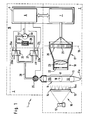
- the automatic pipettor 1 shown in FIG. 1 exists essentially from a detection device 2 for the detection of a liquid phase boundary 10 in the Detection section 8 of a measuring tube 9, and a Auxiliary fluid transfer device 16, to which a switching valve device 3 and a gas pump 4 heard.
- a electronic central unit 5 includes a control unit 6 for the gas pump 4 and the switching valve device 3 and an evaluation unit 7 for the detection device 2 a.
- the detection device 2 is in the case shown a liquid level detection device (LLD), i.e. the phase boundary 10 is the boundary between air and Liquid in a vertical riser 11 Measuring tube 9.
- LLD liquid level detection device
- the LLD is used to measure the height of the Liquid level 10 in the riser 11 automatically to detect.
- the riser 11 from a light source 12 via a light scattering device 13 illuminated with diffuse light.
- the light scattering device In the illustrated case, 13 is a focusing screen 14, whereby the riser pipe 11 on that facing away from the light source 12 Side of the focusing screen 14 and the focusing screen 14 and the riser 11 arranged approximately parallel to each other are.
- the light source 12 and the light scattering device form 13 a lighting device 15 for Illumination of the riser 11.
- a light receiving device 17 On the one opposite the lighting device 15 there is a light receiving device 17, which consists of an optical imaging system 18 for mapping the riser pipe into one Image plane 19 and one arranged in the image plane 19 Row 20 of photosensitive elements, which in the illustrated preferred case CCD elements (pixels) 21 are.
- the light source 12 can consist of one or more lamps, for example halogen lamps, tungsten lamps or the like consist.
- the light scattering device is preferred a screen 14 illuminated from the rear, however, the preferred diffuse in the context of the invention Illumination of the riser 11 also with, for example a diffusely reflecting surface, which is illuminated from the side in such a way that preferably no light from the light source directly on the riser 11 falls.
- a diffusely reflecting surface which is illuminated from the side in such a way that preferably no light from the light source directly on the riser 11 falls.
- the Riser pipe 11 facing surface which as a diffusion surface 14a can be referred to in uniform Distance (i.e. approximately parallel) to this.
- the riser pipe 11 is preferably a capillary with a Inner diameter of less than 1 mm, particularly preferred less than 0.5 mm. Its lower end is in Fluid connection with a liquid transfer port lla through which the liquid is sucked in and expelled can be. "Is in fluid communication (fluid communication) "is to be understood in such a way that the liquid transfer opening 11a - as shown - an opening of the riser 11 itself or by means of a Pipe or hose in indirect connection with the riser 11 can stand.
- the optical imaging system 18 suitably exists from an aperture 22 and one (only in the drawing lens (indicated as a lens) 23.
- the range of photosensitive elements may change also be part of a two-dimensional arrangement that not only parallel to the riser 11, but also extends perpendicular to it in the image plane 19. As sufficient and especially useful has a pure linear arrangement of the CCD pixels has been shown, with their spacing is less than 50 microns, preferably at most 25 microns.
- the Light source 12, the riser 11 and the row 20 of CCD pixel 21 in one plane With this arrangement (and Dosage of a clear liquid) provide CCD pixels, onto which the liquid-filled area of the capillary is mapped, a higher output signal than that Pixels on which the air-filled area of the capillary is imaged becomes.
- FIG. 2 shows a graphical representation A of the output signals the CCD pixel 21 depending on the location X of the capillary riser 11, which is shown on it.
- the output signal of the CCD line sensor was over a Interface transferred to a standard personal computer, which served as evaluation device 7.
- the assignment the CCD output signals for the values "capillary filled” or "capillary empty” was carried out with the help of a according to the set threshold.
- the interface should enable parallel processing of the data ensures the position of the liquid level in real time is.
- the graphs B, C, D of Figures 3 to 5 illustrate the dependence of the measurement signal on the Angular position of the light source 12 and the light scattering device 13. A supervision is shown in each case, the axis of the riser 11 is therefore perpendicular to Drawing level.
- Azimuth angle ⁇ (related to one to the riser 11 vertical plane) the difference of the Pixel output signals that the liquid-filled and correspond to the air-filled section of the riser 11.
- the measuring arrangement is designed so that the brightness of the liquid-filled section and the gas-filled section of the measuring section of the riser 11 clearly distinguish (as in Figure 2, 3 and 5), is the evaluation of the output signal of row 20 the photosensitive elements 21 particularly simple. How in general, it suffices to add a threshold value in this way place it about halfway between the output signals lies that of the filled or the empty capillary correspond. This allows a very good accuracy achieve without a high-precision adjustment of the Components is required. As from Figures 2 to 5 is shown schematically, the intensities change over relatively wide angular ranges only slightly.
- phase boundary detection device according to the invention (PBDM) is that exact localization even in such cases allows the phase boundary in which the brightness the areas of the measuring tube adjacent to the phase boundary does not differ, or differs only very slightly.
- FIG. 6 shows the signal of the CCD pixels in an experiment, in which the measuring section depicted on the CCDs 8 of a measuring tube 9 in successive partial areas Contains water (W), silane oil (O) and again water (W).
- W water
- O silane oil
- W water
- the oil does not mix with water, so that between form water / oil phase boundaries W / O and O / W, respectively.
- the measured output signals are preferably used the CCD pixel is first digital low-pass filtering subjected. Such methods, for example with the help of a Hamming, Blackman, or Hanning window function are known. They lead to smoothing the waveform. This will cause false ads a phase boundary due to random signal fluctuations avoided.
- the signal minimum can be found in the filtered signal curve again with the help of a limit value.
- a limit value is expediently a multiple of the statistical Fluctuation range of the pixel signals below the mean signal value of a defined neighborhood (for example 10 pixels).
- One below this intensity limit is called the phase boundary recognized.
- the automatic shown in Figure 1 includes Pipettor 1 next to the LLD 2 the switching valve device 3, the gas pump 4 and the associated control unit 6.
- the switching valve device 3 consists in the shown preferred embodiment from a quick shut-off valve 25 and two changeover valves 26 and 27.
- the valves 26, 27 each have a first side 26a, 27a a connection and on a second side 26b, 27b two connections, whereby by switching the Valve optionally a connection between the one connection the first side and one of the connectors of the second side is produced.
- the first page 26a of the Valve 26 is connected to the pressure side 4a of the gas pump 4, while the first side 27a of the valve 27 with the suction side 4b of the gas pump is connected.
- valves 26, 27 From the two ports on the second side of the valves 26, 27 are each connected to a Y line system 28, through that a connection to that of that Connection of the shut-off valve 25 facing away from the riser pipe 11 will be produced.
- the other connection of the second Page 26b, 27b of the valves 26,27 is with the outside air connected.
- the valves 26, 27 are switched synchronously so that in a first position (in the figure with shown by solid lines) the pressure side of the Gas pump 4 is connected to the shut-off valve 25 while in a second position (dashed in the figure shown) the suction side 4b with the shut-off valve 25 connected is.
- a bypass 29 with at least one Pressure relief valve 30 is provided.
- the changeover valves 26, 27 brought into the position shown in dashed lines, so that a negative pressure generated by the gas pump 4 is applied to the shut-off valve 25.
- this Valve connects to the gas space 11b of the Riser pipe 11 made above the liquid level 10.
- the liquid is sucked in and the liquid level 10 increases under the control of LLD 2.
- the valve control signal is from the control unit 6 depending on one of the Evaluation unit 7 generated electrical signal, which corresponds to the level of the liquid level 10, by comparison with a desired altitude corresponding setpoint is generated.
- the switching valve device 3 can, as the person skilled in the art is common to be constructed in a different way, for example using a four-way valve or by four one-way valves, which are switched synchronously, that at the desired time gas the gas space 11b is supplied or removed therefrom.
- phase boundary 10 is an interface between those located in the lower part of the measuring tube 9 Liquid column 32 and that in the gas space 11b air.
- a liquid instead of the gas (air) become.
- a liquid pump for example a piston pump
- a liquid reservoir Sucks in liquid or in it or deliver another container.
- Fluids gas or liquids
- the liquid to be dosed to suck into or to eject from the measuring tube 9 is the embodiment with a gas (in particular Air) particularly preferred because it is special is simple and every contact of the liquid to be dosed with another liquid.
- a gas in particular Air
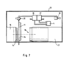
- the Lighting device 15 has a light-tight closed Housing in which the light source, not shown located. On the riser 11 facing Side of the lighting device 15 is the ground glass 14 attached.
- the light receiving device 17 is also including the imaging optical system 18 in housed in a common light-tight closed housing.
- the connecting lines between the gas pump 4, the changeover valves 25, 26, the pressure relief valve 30 and the solenoid valve 25 are formed by hoses.
- the riser pipe 11 is a very thin capillary attached to the frame 33 by means of a support part 34 is.
- the riser pipe 11 fixed. It can therefore occur during pipetting not be moved up and down. If such Movement is desired, it can be within the scope of the present Realize invention either by that Riser pipe 11 in a precisely predetermined and measurable manner and way is moving up and down and this movement by the evaluation unit 7 when calculating the level (and the resulting volume) in the riser is taken into account. There is a second possibility in using a fixed standpipe and on it lower end over a flexible hose one separately Movable pipetting needle with the liquid transfer opening to connect.
Landscapes
- Physics & Mathematics (AREA)
- Electromagnetism (AREA)
- General Physics & Mathematics (AREA)
- Thermal Sciences (AREA)
- Fluid Mechanics (AREA)
- Analytical Chemistry (AREA)
- General Health & Medical Sciences (AREA)
- Health & Medical Sciences (AREA)
- Life Sciences & Earth Sciences (AREA)
- Chemical & Material Sciences (AREA)
- Engineering & Computer Science (AREA)
- Biochemistry (AREA)
- Robotics (AREA)
- Immunology (AREA)
- Pathology (AREA)
- Automatic Analysis And Handling Materials Therefor (AREA)
- Investigating Or Analysing Materials By Optical Means (AREA)
- Measurement Of Levels Of Liquids Or Fluent Solid Materials (AREA)
- Length Measuring Devices By Optical Means (AREA)
- Sampling And Sample Adjustment (AREA)
Description
Die Erfindung betrifft eine Vorrichtung zum automatischen exakten Dosieren kleiner Flüssigkeitsmengen in einem medizinischen Analysegerät umfassend eine Vorrichtung zur Detektion einer Flüssigkeits-Phasengrenze in einem lichtdurchlässigen Meßrohr.The invention relates to a Automatic device exact dosing of small amounts of liquid in a medical Analysis device comprising a device for detection a liquid phase boundary in a translucent Measuring tube.
Vorrichtungen zur Detektion einer Flüssigkeits-Phasengrenze in einem Meßrohr werden vielfach benötigt. Als Flüssigkeits-Phasengrenze ist dabei jede Grenzfläche zwischen einer Flüssigkeit und einer in Phasengrenzkontakt zu dieser stehenden optisch unterscheidbaren Phase, welche gasförmig, flüssig oder auch fest sein kann, anzusehen. Devices for the detection of a liquid phase boundary are often required in a measuring tube. As The liquid phase boundary is every interface between a liquid and one in phase contact to this standing optically distinguishable phase, which can be gaseous, liquid or solid.
Gebräuchlich sind vor allem Vorrichtungen zur Detektion des Höhenstandes einer Flüssigkeit in einem aufrecht stehenden Meßrohr, das nachfolgend als Steigrohr bezeichnet wird. Sie werden in Fachkreisen gemäß einer gebräuchlichen englischen Ausdrucksweise auch als LLD (Liquid Level Detector) bezeichnet. Insbesondere richtet sich die Erfindung auf Anwendungsfälle im Zusammenhang mit Geräten zur Analyse von Körperflüssigkeiten (vor allem Blut und Urin). Dabei geht es insbesondere um die Detektion der Flüssigkeits-Phasengrenze von Proben oder flüssigen Reagenzien.Devices are mostly used for detection of the level of a liquid in an upright position standing measuring tube, hereinafter referred to as a riser becomes. They are used in specialist circles according to a English expression also as LLD (Liquid Level Detector). In particular, the Invention for use cases in connection with devices for the analysis of body fluids (especially blood and Urine). It is particularly about the detection of Liquid phase boundary of samples or liquid reagents.
Soweit sich die Flüssigkeit in einem offenen Gefäß befindet, läßt sich ihr Höhenstand mit Hilfe einer von oben eintauchenden Sonde detektieren, wobei die Sonde zumeist gleichzeitig eine Pipettenspitze ist, durch die ein Reagenz- oder Probenflüssigkeit zugeführt oder abgesaugt werden kann. An der Spitze der Sonde bzw. der Pipette befindet sich ein Flüssigkeitsdetektor, der beim Eintauchen - unter Umständen auch bereits kurz vor dem Eintauchen - in die Flüssigkeit ein Signal erzeugt. Hierfür sind verschiedene Prinzipien bekannt, die beispielsweise auf der Bestimmung des elektrischen Widerstandes oder der elektrischen Kapazität zwischen zwei an der Spitze der Pipette angebrachten Elektroden basieren. Es sind auch bereits optische Prinzipien für derartige Anwendungsfälle diskutiert worden (europäisches Patent 0250671). Bei diesen Verfahren gibt die Position der Sonde bzw. Pipette beim Eintauchen in die Flüssigkeit ein Maß für die Höhe des Flüssigkeitsspiegels.As far as the liquid is in an open vessel, their height can be adjusted with the help of one from above Detect immersed probe, the probe mostly is also a pipette tip through which a reagent or sample liquid supplied or aspirated can be. Located at the tip of the probe or pipette a liquid detector when immersed - possibly even shortly before immersion - generates a signal in the liquid. There are several for this Principles known, for example, on the Determination of electrical resistance or electrical Capacity between two at the tip of the pipette attached electrodes based. There are already optical principles for such applications have been discussed (European patent 0250671). With these The method gives the position of the probe or pipette a measure of the height when immersed in the liquid of the liquid level.
Die Erfindung richtet sich insbesondere, jedoch nicht ausschließlich, auf die Bestimmung der Flüssigkeits-Phasengrenze in einer Dosiervorrichtung mit einem nach oben hin geschlossenen Steigrohr. Für solche Anwendungsfälle wurden optische Meßprinzipien vorgeschlagen, bei denen das Steigrohr mit einer mindestens eine Lichtquelle aufweisenden Beleuchtungseinrichtung beleuchtet wird, eine Lichtempfangseinrichtung mit mindestens einem Lichtempfänger vorgesehen ist, die einen Teil des durch das Steigrohr bzw. die darin enthaltene Flüssigkeit hindurchtretenden Lichtes empfängt und in von dessen ortsabhängiger Intensitätsverteilung abhängige elektrische Signale umwandelt. Die Signale der Lichtempfangseinrichtung werden einer elektronischen Auswerteeinrichtung zugeführt, um daraus die gewünschte Information über den Höhenstand des Flüssigkeitsspiegels in dem Steigrohr abzuleiten.The invention is directed in particular, but not exclusively, on the determination of the liquid phase boundary in a dosing device with a rising tube closed at the top. Optical measuring principles have been used for such applications proposed in which the riser pipe with a minimum a lighting device having a light source is illuminated with a light receiving device at least one light receiver is provided, the one Part of the through the riser pipe or the contained therein Liquid receiving light receives and in from whose location-dependent intensity distribution dependent converts electrical signals. The signals of the light receiving device become an electronic evaluation device fed to the desired information about the level of the liquid level in the Derive the riser pipe.
Die Realisierung dieses einfach erscheinenden Prinzips verursacht erhebliche Probleme, vor allem wenn der Höhenstand in einem kapillarförmigen Steigrohr mit sehr dünnem Innendurchmesser mit hoher Präzision bestimmt werden soll.The realization of this simple principle causes significant problems, especially when the altitude in a capillary tube with a very thin tube Inner diameter can be determined with high precision should.
In der deutschen Patentschrift 28 55 651 wird auf die
Probleme mit den unterschiedlichen bekannten optischen
Meßprinzipien (Bestimmung der Abdunklung durch eine gefärbte
Flüssigkeit bzw. der Aufhellung durch eine klare
Flüssigkeit; Meniskusabtastung; Reflexions- bzw. Streulichtprinzip)
hingewiesen. Es wird eine bestimmte elektronische
Schaltung vorgeschlagen, um durch Verbesserung
der Signalverarbeitung die optischen Probleme zu kompensieren.In the
Bei der Detektion von Flüssigkeiten in medizinischen Analysegeräten
ist die Problematik vor allem dadurch erschwert,
daß die Reagenzien und Proben meist nur sehr
wenig gefärbt sind. Darüber hinaus ist die Färbung von
Probe zu Probe oder von Reagenz zu Reagenz unterschiedlich,
und dennoch soll der Höhenstand unabhängig von diesen
Unterschieden präzise erfaßt werden. In der deutschen
Patentschrift 28 55 651 wird bereits darauf hingewiesen,
daß ein früherer Vorschlag zur Lösung dieser Probleme
vorsieht, den Zylinderlinseneffekt der in dem Steigrohr
befindlichen Flüssigkeit auszunutzen. Beispielsweise kann
das durch das flüssigkeitsgefüllte Rohr fokussierte Licht
mittels einer Blende von der Photozelle ferngehalten werden.
Wenn der Flüssigkeitsspiegel in dem Steigrohr soweit
abfällt, daß die betreffende Stelle des Rohres leer ist,
verändert sich die Brennweite dieser Zylinderlinse wobei
ein Teil des Lichtes auf die Photozelle trifft.For the detection of liquids in medical analyzers
the main problem is that
that the reagents and samples mostly only very much
are little colored. In addition, the coloring of
Sample to sample or different from reagent to reagent,
and yet the level should be independent of these
Differences can be recorded precisely. In the
Auch in der europäischen Patentanmeldung 0185285 wird das Problem der Detektion einer weitgehend transparenten medizinischen Flüssigkeiten diskutiert. Zur Lösung wird auch hier das vorstehend beschriebene Prinzip verwendet, wobei in diesem Fall das flüssigkeitsgefüllte Steigrohr als Linse dient, um ein schmales Lichtband auf eine der Lichtquelle (bezogen auf das Steigrohr) gegenüberliegende Fläche zu fokussieren. Dabei ist es wichtig, daß das Steigrohr eine bestimmte (zylindrische) Form hat und die geometrischen Bedingungen der Fokussierung genau eingehalten werden. Es wird auch eine Ausführungsform beschrieben, bei der die Lichtempfangseinrichtung eine Mehrzahl von Lichtempfängern in Form von Photozellen, Photowiderständen, Photodioden, Phototransistoren oder dergleichen aufweist, die jeweils gegenüber einem Lichtsender parallel zu dem Steigrohr angeordnet sind, so daß sie eine Vielzahl von dicht übereinander angeordneten Lichtschranken bilden. Diese Anordnung ermöglicht zwar eine bequeme Höhenstanderfassung, kann jedoch hinsichtlich der Auflösung und Präzision der Höhenstandsbestimmung nur geringe Ansprüche erfüllen. Es wird mit einem Abstand der lichtempfindlichen Elemente von 1 mm gearbeitet und eine Präzision der Volumenbestimmung in dem Steigrohr von etwa 100 µl erreicht. Daraus ergibt sich, daß ein verhältnismäßig dickes Steigrohr mit einem Innendurchmesser von etwa 5 mm verwendet wurde. Zur Detektion der Phasengrenze in einem kapillarförmigen Meßrohr mit einem Innendurchmesser von beispielsweise weniger als 1 mm ist das in der europäischen Patentanmeldung verwendete, auf der unterschiedlichen Fokussierung des gefüllten und des leeren Meßrohres basierende Prinzip nicht geeignet.This is also the case in European patent application 0185285 Problem of detection of a largely transparent medical fluids discussed. The solution is also uses the principle described above, in this case the liquid-filled riser pipe serves as a lens to apply a narrow band of light to one of the Light source (related to the riser) opposite Focus area. It is important that Riser pipe has a certain (cylindrical) shape and the geometrical conditions of focusing exactly adhered to become. An embodiment is also described in which the light receiving device a Plurality of light receivers in the form of photocells, Photoresistors, photodiodes, phototransistors or The like, each opposite a light transmitter are arranged parallel to the riser pipe, so that they have a multitude of densely arranged one above the other Form light barriers. This arrangement allows a comfortable level detection, but can with regard the resolution and precision of the height determination meet only minor requirements. It will be with one Working distance of the photosensitive elements of 1 mm and a precision of volume determination in the Rise tube of approximately 100 µl reached. This results in, that a relatively thick riser pipe with an inner diameter of about 5 mm was used. For detection the phase boundary in a capillary measuring tube an inner diameter of, for example, less than 1 mm is the one used in the European patent application on the different focus of the filled and the principle of the empty measuring tube is not suitable.
Bei einer in der deutschen Patentanmeldung 36 05 403 beschriebenen Vorrichtung basiert die Detektion des Flüssigkeitshöhenstandes darauf, daß ein kontinuierlicher Übergang der gemessenen Lichtintensität im Bereich des Flüssigkeitsspiegels erreicht wird. Hierzu wird eine parallel zu dem Steigrohr verlaufende linienförmige Lichtquelle in Verbindung mit einer Reihe von unmittelbar an dem Steigrohr vorgesehenen Detektoren verwendet. Es wird als unbedingt erforderlich angesehen, daß ein Unterschied bezüglich der detektierten Lichtintensität zwischen dem flüssigkeitsgefüllten und dem gasgefüllten Bereich des Steigrohres besteht. Dieser Unterschied wird dadurch sichergestellt, daß entweder die Flüssigkeit eingefärbt wird oder (wie bei den zuvor beschriebenen Vorrichtungen) der Zylinderlinseneffekt beim Durchgang des Lichtes durch das Steigrohr genutzt wird.In one described in German patent application 36 05 403 Device based the detection of the liquid level insist that a continuous Transition of the measured light intensity in the range of Liquid level is reached. This is done in parallel linear light source running to the riser in conjunction with a number of immediately detectors provided to the riser. It will viewed as essential to make a difference regarding the detected light intensity between the liquid-filled and the gas-filled area of the Riser pipe. This difference becomes apparent ensured that either the liquid was colored or (as in the previously described devices) the cylindrical lens effect when the light passes through the riser pipe is used.
In dem wissenschaftlichen Artikel "Optical device for the measurement of small volume changes" von A.K. Davies et al. Applied Optics, 1986, 1245 f ist eine Vorrichtung beschrieben, die zur Erfassung des Höhenstandes (und damit des Volumens) in einem Kapillarrohr von 50 µl Volumen dienen soll. Dieser Vorschlag bedingt einen hohen technischen Aufwand. Das Licht wird schmalbandig gefiltert. Es muß ein spezieller Einstrahlwinkel (28°) gewählt werden unter dem das Licht auf die Kapillare auftrifft. Die dahinter liegende Photozelle muß zusätzlich durch spezielle Anordnungen von Blenden abgeschirmt werden. Dennoch ist die Detektion der Phasengrenze zwischen Flüssigkeit und Luft nicht in allen Bereichen der Kapillare möglich, sondern nur die zentralen 20% der Kapillare werden verwendet. Das auf der Auswertung einer analogen Signaländerung basierende Prinzip bedarf einer exakten Kalibration.In the scientific article "Optical device for the measurement of small volume changes "by A.K. Davies et al. Applied Optics, 1986, 1245 f is a device described for the detection of the altitude (and thus of the volume) in a capillary tube of 50 µl volume should serve. This proposal requires a high level of technology Expenditure. The light is filtered in a narrow band. It a special angle of incidence (28 °) must be selected under which the light hits the capillary. The one behind it lying photocell must also by special Arrangements of screens are shielded. Still is the detection of the phase boundary between liquid and Air is not possible in all areas of the capillary, but only the central 20% of the capillary is used. That on the evaluation of an analog signal change based principle requires exact calibration.
Aus dem Dokument Patent Abstracts of Japan, vol. 9, no. 232 (P-389)(1955) 18. September 1985, JP-A-60 086 439 ist eine Vorrichtung zum Messen eines vorgegebenen Probenvolumens für eine Serumanalyse bekannt. Es wird vorgeschlagen, parallele Lichtstrahlen durch das Meßrohr durchtreten zu lassen und mittels Lichtleitelementen auf eine eindimensionale Anordnung lichtempfindlicher Elemente zu lenken. Eine genaue Dosierung kleiner Flüssigkeitsmengen ist damit nicht möglich. From the Patent Abstracts of Japan document, vol. 9, no. 232 (P-389) (1955) September 18, 1985, JP-A-60 086 439 is an apparatus for Measure a given sample volume known for a serum analysis. It is suggested, parallel rays of light through the Let the measuring tube pass through and Light guiding elements on a one-dimensional Arrangement of photosensitive elements to steer. An exact dosage of small amounts of liquid is not possible with it.
Um ein automatisches, exaktes Dosieren kleiner Flüssigkeitsmengen mit einer genauen, zuverlässigen Bestimmung der Position der Phasengrenze, insbesondere in einem Meßrohr mit sehr kleinem (kapillaren) Durchmesser (insbesondere in Fällen, bei denen sich die optische Helligkeit der Medien auf beiden Seiten der Phasengrenze wenig oder gar nicht unterscheidet) zu ermöglichen, richtet sich die Erfindung gemäß einem ersten Hauptaspekt auf eine Vorrichtung zur Detektion einer Flüssigkeits-Phasengrenze in einem lichtdurchlässigen Meßrohr mit einer Beleuchtungseinrichtung mit mindestens einer Lichtquelle zur Beleuchtung des Meßrohres, einer Lichtempfangseinrichtung mit mindestens einem Lichtempfänger, die durch das Meßrohr hindurchtretendes Licht empfängt und in von dessen ortsabhängiger Intensitätsverteilung abhängige elektrische Signale umwandelt und einer Auswerteeinheit zur Verarbeitung der Signale der Lichtempfangseinrichtung zu einer Information über die Position der Flüssigkeits-Phasengrenze in dem Meßrohr, bei welcher die Beleuchtungseinrichtung zur stetigen Beleuchtung eines Detektionsabschnittes des Meßrohres ausgebildet ist und die Lichtempfangseinrichtung ein optisches Abbildungssystem zur Abbildung des Detektionsabschnittes in eine Bildebene und eine Reihe eng benachbarter lichtempfindlicher Elemente in der Bildebene aufweist. To ensure an automatic, exact dosing of small amounts of liquid with an accurate, reliable determination of the position of the Phase boundary, especially in a measuring tube with very small (capillary) diameter (especially in cases where the optical brightness of the media is up either side of the phase boundary little or no differs) to enable, the invention is directed according to a first main aspect of a device for Detection of a liquid phase boundary in a translucent Measuring tube with a lighting device with at least one light source for illuminating the Measuring tube, a light receiving device with at least a light receiver that passes through the measuring tube Light receives and depends on its location Intensity distribution dependent electrical signals converts and an evaluation unit for processing the Signals from the light receiving device for information about the position of the liquid phase boundary in the Measuring tube in which the lighting device for steady illumination of a detection section of the Measuring tube is formed and the light receiving device an optical imaging system for imaging the Detection section in an image plane and a row closely adjacent photosensitive elements in the Has image plane.
Die lichtempfindlichen Elemente in der Bildebene des zweckmäßigerweise als optisches Abbildungssystem dienenden Objektivs sind vorzugsweise ein lineares Array von CCD-Elementen (charged coupled devices). Der Abstand der lichtempfindlichen Elemente beträgt vorzugsweise weniger als 50 µm.The photosensitive elements in the image plane of the expediently serving as an optical imaging system Lenses are preferably a linear array of CCD elements (charged coupled devices). The distance of the photosensitive elements is preferably less than 50 µm.
Erfindungsgemäß kann die Position einer Flüssigkeits-Phasengrenze in einem Meßrohr mit sehr kleinem Durchmesser von weniger als 1 mm, besonders bevorzugt sogar weniger als 0,5 mm zuverlässig und genau detektiert werden.According to the invention, the position of a liquid phase boundary in a measuring tube with a very small diameter less than 1 mm, particularly preferably even less than 0.5 mm can be reliably and accurately detected.
Die Erfindung ermöglicht die Positionsbestimmung der Flüssigkeits-Phasengrenze in derartig dünnen Kapillaren ohne bewegliche Teile. Dadurch, daß die Flüssigkeitssäule in dem Meßrohr über einen längeren Detektionsabschnitt mit hoher Auflösung erfaßt wird, ist es zusätzlich möglich, typische Fehlerquellen, wie Luftblasen oder Verunreinigungen, mit Hilfe eines von einer mikroprozessorgesteuerten Auswerteeinrichtung durchgeführten Detektionsalgorithmus zu eliminieren.The invention enables the position determination of the Liquid phase boundary in such thin capillaries without moving parts. Because the liquid column in the measuring tube over a longer detection section is recorded with high resolution, it is also possible typical sources of error, such as air bubbles or contamination, using one of a microprocessor controlled Evaluation device carried out detection algorithm to eliminate.
Die Beleuchtung des Detektionsabschnittes muß stetig sein in dem Sinne, daß (im Gegensatz zu Lichtschranken) keine plötzlichen Änderungen der räumlichen Verteilung der Beleuchtungsintensität vorkommen. Eine solche stetige Beleuchtung läßt sich mit verschiedenen bekannten Mitteln erreichen, beispielsweise mit Hilfe einer länglich ausgedehnten (zum Beispiel röhrenförmigen), parallel zu dem Meßrohr verlaufenden Lichtquelle, einer Vielzahl von parallel zu dem Meßrohr dicht beieinander angeordneten Lichtquellen oder einer Beleuchtungsoptik, die das Licht einer einfachen Lichtquelle (z.B. Halogenlampe) entsprechend aufweitet. Wesentlich bevorzugt ist jedoch eine Ausführungsform, bei der die Beleuchtungseinrichtung eine Lichtstreueinrichtung, insbesondere mit einer parallel zu dem Meßrohr verlaufenden Mattscheibe (oder anderen Diffusionsfläche) aufweist. Dadurch wird mit geringem konstruktiven Aufwand und ohne exakte Positionierung der Lichtquelle eine besonders genaue Detektion der Phasengrenze ermöglicht.The illumination of the detection section must be steady in the sense that (unlike light barriers) none sudden changes in the spatial distribution of lighting intensity occurrence. Such steady lighting can be done by various known means achieve, for example with the help of an elongated (for example tubular), parallel to that Measuring tube running light source, a variety of parallel arranged close to the measuring tube Light sources or lighting optics that light corresponding to a simple light source (e.g. halogen lamp) expands. However, one is essentially preferred Embodiment in which the lighting device Light scattering device, in particular with a parallel to the focusing screen (or other diffusion surface) having. This will result in little constructive Effort and without exact positioning of the Light source a particularly precise detection of the phase boundary enables.
Der Aufbau ist verhältnismäßig einfach. Es sind keine Blenden, Filter oder Abschirmungen erforderlich. Es kann eine außerordentlich hohe Genauigkeit und Präzision erreicht werden. Beispielsweise wurden mit der Erfindung in einer Kapillare mit einem Innendurchmesser von 0,2 mm und einem Abstand der CCD-Elemente (Pixel) von 25 µm Volumenunterschiede von +/- 1 nl zuverlässig detektiert.The structure is relatively simple. There are not any Apertures, filters or shields required. It can extremely high accuracy and precision become. For example, with the invention in a capillary with an inner diameter of 0.2 mm and a distance of the CCD elements (pixels) of 25 µm volume differences of +/- 1 nl reliably detected.
Das System arbeitet ohne bewegliche Teile und verzögerungsfrei. Es ist möglich, die zeitliche Änderung der Position der Phasengrenze genau zu erfassen und beispielsweise deren Bewegungsgeschwindigkeit zu bestimmen.The system works without moving parts and without delay. It is possible to change the time Position of the phase boundary to be recorded precisely and for example to determine their speed of movement.
Die Erfindung richtet sich auf eine Vorrichtung zum automatischen exakten Dosieren kleiner Flüssigkeitsmengen. Solche Vorrichtungen werden auch als (automatische) Pipettoren bezeichnet. Sie werden im Zusammenhang mit der Analyse von Körperflüssigkeiten, insbesondere bei entsprechenden Analysegeräten, vielfach verwendet, um Proben und Reagenzien von einem Gefäß in ein anderes Gefäß zu transferieren. Die Dosierung der Flüssigkeit basiert dabei auf der Bewegung eines Kolbens in einem Präzisionsrohr. Der Kolben wird in der Regel von einem Schrittmotor angetrieben, dessen Bewegung über einen Zahnriemen auf einen Spindelantrieb übertragen wird. Dieser Spindelantrieb bewegt einen Schlitten, der üblicherweise fest mit dem Kolben verbunden ist. Die Präzision der Dosierung mit einer solchen Kolbenpumpe ist abhängig von der Präzision des Schrittmotors und der Genauigkeit der Übertragungselemente (Zahnriemen, Spindelantrieb). Um eine hohe Präzision zu gewährleisten, müssen die mechanischen Teile sehr genau gefertigt werden und sind demzufolge teuer. Die mechanisch beweglichen Teile können verschleißen und müssen, um die Genauigkeit zu gewährleisten, regelmäßig gewartet werden. Zusätzliche Fehler hinsichtlich der Dosierungspräzision können durch Unterschiede in der Konsistenz, Zähigkeit oder dem Fettgehalt der zu dosierenden Flüssigkeit entstehen. Solche Unterschiede sind bei Blut und den in der medizinischen Analytik gebräuchlichen Reagenzflüssigkeiten, welche Proteine und andere Riesenmoleküle enthalten, besonders ausgeprägt.The invention is directed to a device for automatic exact dosing of small amounts of liquid. Such devices are also called (automatic) Referred to as pipettors. You will be related with the analysis of body fluids, especially at corresponding analyzers, widely used to Samples and reagents from one vial to another Transfer vessel. The dosage of the liquid is based on the movement of a piston in one Precision tube. The piston is usually made by one Stepper motor driven, its movement over a Toothed belt is transferred to a spindle drive. This spindle drive moves a carriage that is usually firmly connected to the piston. The precision dosing with such a piston pump depending on the precision of the stepper motor and the accuracy the transmission elements (toothed belt, spindle drive). To ensure high precision, the mechanical parts are manufactured very precisely and are therefore expensive. The mechanically moving parts can wear out and need to ensure accuracy be serviced regularly. Additional bugs in terms of dosing precision may vary in consistency, toughness or fat content of the liquid to be dosed. Such differences are in blood and in medical Analytics common reagent liquids, which proteins and contain other giant molecules, particularly pronounced.
Die Erfindung stellt einen automatischen Pipettor mit hoher Genauigkeit, insbesondere zur Dosierung von sehr kleinen Probenvolumina zur Verfügung. Sie weist eine Phasengrenzdetektionsvorrichtung ("Phase Boundary Detection Means, PBDM") auf, durch die eine Flüssigkeits-Phasengrenze in einem Meßrohr automatisch detektiert und ein der Position der Phasengrenze in einem Detektionsabschnitt des Meßrohres entsprecnendes elektrisches Signal erzeugt wird. Mit einem ersten Ende des Meßrohres steht eine Flüssigkeitstransferöffnung zum Ansaugen und Ausstoßen von Flüssigkeit in Fluidverbindung. Mit einem zweiten Ende des Meßrohres steht eine Hilfsfluid-Transfereinrichtung (Auxiliary Fluid Transfer Means, AFTM) zum präzise gesteuerten Zuführen und Absaugen eines Hilfsfluids zu bzw. von dem Meßrohr in Fluidverbindung. Sie weist Mittel zum Zuführen von Hilfsfluid (Auxiliary Fluid Supply Means, AFSM) und Mittel zum Absaugen von Hilfsfluid (Auxiliary Fluid Withdrawl Means, AFWM) auf. Eine elektronische Steuereinheit ist vorgesehen, um die Hilfsfluid-Transfereinrichtung in Abhängigkeit von dem der Position der Flüssigkeits-Phasengrenze entsprechenden Signal derart anzusteuern, daß durch Absaugen bzw. Zuführen von Hilfsfluid zu dem Meßrohr präzise definierte Flüssigkeitsmengen angesaugt bzw. ausgestoßen werden.The invention provides an automatic pipettor with high accuracy, especially for dosing very small sample volumes to disposal. It has a phase boundary detection device ("Phase Boundary Detection Means, PBDM") through which a liquid phase boundary in a measuring tube automatically detected and a the position of the phase boundary in a detection section of the measuring tube electrical signal is generated. With a first ending the measuring tube is a liquid transfer opening to Sucking and ejecting fluid in fluid communication. With a second end of the measuring tube is one Auxiliary fluid transfer device Means, AFTM) for precisely controlled feeding and suction of an auxiliary fluid to or from the measuring tube in fluid communication. It has means for supplying auxiliary fluid (Auxiliary Fluid Supply Means, AFSM) and means for suction Auxiliary Fluid Withdrawl Means, AFWM). An electronic control unit is provided depending on the auxiliary fluid transfer device from that of the position of the liquid phase boundary to control the corresponding signal such that Suction or supply of auxiliary fluid to the measuring tube precisely defined amounts of liquid sucked in or be expelled.
Die Detektionsvorrichtung zur Detektion der Flüssigkeits-Phasengrenze
ist gemäß Anspruch 1 ausgebildet.
Dabei kann ein dünnes Kapillarröhrchen
als Meßrohr verwendet werden, welches unmittelbar
in die Flüssigkeit eingetaucht wird, wobei die
Höhe des Flüssigkeitsspiegels mit dem LLD gemäß
der Erfindung in relativ kurzem Abstand
über der Ansaugöffnung präzise bestimmt wird. Da
das Probevolumen dabei direkt in dem als Pipettenspitze
dienenden Kapillarrohr gemessen werden kann und deswegen
das angesaugte Volumen direkt und unmittelbar bestimmt
wird, bleiben unterschiedliche Bedingungen, wie Luftdruck,
Raumtemperatur oder Viskosität der Flüssigkeit
praktisch ohne Einfluß auf die Dosierpräzision.The detection device for the detection of the liquid phase boundary
is designed according to
Dabei kann das Meßrohr als einmalverwendbare (disposible) Kapillare ausgebildet sein, welche in eine automatische Halterung des Pipettors eingesetzt wird. Hierdurch wird das Risiko der Übertragung von Flüssigkeitsresten auf das jeweils nächste dosierte Flüssigkeitsvolumen ("Verschleppung") vollständig vermieden. Bei vorbekannten Konstruktionen führten disposible Pipettenspitzen an automatischen Pipettoren infolge unvermeidlicher Unterschiede der Ankopplung an den Pipettor zu großen Präzisionsproblemen beim Pipettieren von sehr kleinen Volumina.The measuring tube can be used as a disposable Capillary be formed, which in an automatic Holder of the pipettor is used. This will the risk of transferring liquid residues to the each next metered volume of liquid ("Procrastination") completely avoided. With previously known Constructions cited disposable pipette tips automatic pipettors due to inevitable differences the coupling to the pipettor to great precision problems when pipetting very small Volumes.
In Verbindung mit dem Pipettor gemäß der Erfindung kann ein LLD eingesetzt werden, der den Höhenstand einer Flüssigkeit in einem nach oben geschlossenen Steigrohr automatisch detektiert und ein resultierendes elektrisches Signal erzeugt, welches der Steuereinheit zugeführt wird, um das Ansaugen und Ausstoßen der Flüssigkeit präzise zu kontrollieren. Bekannte Vorrichtungen dieser Art wurden einleitend erwähnt.In connection with the pipettor according to the invention can be a LLD are used, the level of a Liquid in a riser tube closed at the top automatically detected and a resulting electrical Generates signal, which is fed to the control unit is used to suck and expel the liquid to control precisely. Known devices of this Art were mentioned in the introduction.
Das Hilfsfluid kann ein Gas oder eine Flüssigkeit sein. Eine Flüssigkeit kann zweckmäßigerweise mit Hilfe einer Kolbenpumpe präzise gesteuert zugeführt bzw. abgesaugt werden. Wenn die Hilfsflüssigkeit mit der zu dosierenden Flüssigkeit nicht mischbar ist, kann an der Phasengrenze ein unmittelbarer Kontakt zwischen beiden Flüssigkeiten bestehen. Auch mit einer mischbaren Flüssigkeit kann gearbeitet werden, indem man zwischen Hilfsflüssigkeit und zu dosierender Flüssigkeit eine Gasblase ansaugt. Diese Trennung zweier unterschiedlicher Flüssigkeiten mit Hilfe einer Gasblase ist in der Analysetechnik gebräuchlich. In diesem Fall wird eine der Phasengrenzen zwischen der zu dosierenden Flüssigkeit oder der Hilfsflüssigkeit und der Gasblase detektiert.The auxiliary fluid can be a gas or a liquid. A liquid can expediently with the help of a Piston pump supplied or extracted with precise control become. If the auxiliary liquid with the to be dosed Liquid immiscible can be at the phase boundary direct contact between the two liquids consist. You can also work with a miscible liquid between the auxiliary liquid and a gas bubble is sucked in. This Separation of two different liquids with the help a gas bubble is common in analysis technology. In in this case one of the phase boundaries between the dosing liquid or the auxiliary liquid and the Gas bubble detected.
Bevorzugt ist eine Ausführungsform, bei der das Hilfsfluid ein Gas, insbesondere Luft ist und das Meßrohr als Steigrohr im wesentlichen vertikal verläuft. Die Phasengrenze ist dabei der Flüssigkeitsspiegel, der die Flüssigkeitssäule in dem Steigrohr von dem darüber befindlichen Gasraum trennt, dem das gasförmige Hilfsfluid zugeführt bzw. von dem es abgesaugt wird. In diesem Fall weist die Transfereinrichtung für das Hilfsfluid vorzugsweise eine Umschaltventileinrichtung auf, die aus einem Mehrwege-Ventil oder mehreren Einzelventilen bestehen kann. In jedem Fall sollte mindestens ein Absperrventil (d.h. ein Ventil, welches schnell zwischen einer Offen- und Geschlossenstellung wechselt) dicht beim oberen Ende des Steigrohres angeordnet sein.An embodiment is preferred in which the auxiliary fluid is a gas, in particular air and the measuring tube as Riser pipe runs essentially vertically. The phase boundary is the liquid level, which is the liquid column in the riser pipe from the one above Separates gas space to which the gaseous auxiliary fluid is supplied or from which it is sucked off. In this case preferably has the transfer device for the auxiliary fluid a switching valve device, which consists of a Multi-way valve or several individual valves exist can. In any case, there should be at least one shut-off valve (i.e. a valve that quickly moves between an open and closed position changes) close to the upper end of the riser pipe.
Der erfindungsgemäße automatische Pipettor ist besonders geeignet zum vollautomatischen Pipettieren sehr kleiner Flüssigkeitsmengen (im Bereich zwischen 20 nl und 20 µl, d.h. 2 x 10⁻⁸ l bis 2 x10⁻⁵ l). Dabei wird eine sehr hohe Präzision erreicht. Bei 100 nl Dosiervolumen liegt der Variationskoeffizient (VK) beispielsweise bei maximal 1 % (d.h. 10-10l). Dabei wird als Meßrohr eine dünne Kapillare mit einem Innendurchmesser zwischen 0,1 mm und 0,3 mm verwendet, die unmittelbar in die zu pipettierende Flüssigkeit eingetaucht (d.h. die Flüssigkeitstransferöffnung ist ein Bestandteil des Meßrohres).The automatic pipettor according to the invention is particularly suitable for the fully automatic pipetting of very small amounts of liquid (in the range between 20 nl and 20 μl, ie 2 x 10 -8 l to 2 x10 -5 l). A very high level of precision is achieved. With 100 nl dosing volume, the coefficient of variation (CV) is, for example, a maximum of 1% (ie 10 -10 l). A thin capillary with an inner diameter between 0.1 mm and 0.3 mm is used as the measuring tube, which is immersed directly in the liquid to be pipetted (ie the liquid transfer opening is a component of the measuring tube).
Die Kontrolle einer dosierten Flüssigkeitsmenge mittels eines optischen LLD ist aus der deutschen Patentschrift 35 15 890 bekannt. Die dort beschriebene Vorrichtung erlaubt jedoch nur eine verhältnismäßig grobe Dosierung einer relativ großen Flüssigkeitsmenge (0,3 ml = 300 µl). Die Funktion unterscheidet sich in wesentlichen Elementen von der hier beschriebenen Vorrichtung. Insbesondere wird die Flüssigkeit mittels einer dem Meßrohr nachgeschalteten Injektor-Sprühdüse aus dem Meßrohr abgesaugt. Es sind weder Mittel zum Zuführen noch zum Absaugen eines Hilfsfluid an dem der Flüssigkeitstransferöffnung gegenüberliegenden Ende des Meßrohres angeschlossen. Mit der vorbekannten Vorrichtung ist es nicht möglich, eine schnelle und verschleppungsarme Dosierung einer Folge unterschiedlicher Flüssigkeiten durchzuführen, wie dies bei klinischen Analysegeräten erforderlich ist. Ebenso ist es unmöglich, damit Flüssigkeiten zu dosieren, die in sehr geringen Mengen vorliegen und daher praktisch ohne Totvolumen dosiert werden müssen.The control of a metered amount of liquid by means of an optical LLD is from the German patent 35 15 890 known. The device described there allows however, only a relatively rough dosage of one relatively large amount of liquid (0.3 ml = 300 µl). The function differs in essential elements from the device described here. In particular the liquid by means of a downstream of the measuring tube Injector spray nozzle sucked out of the measuring tube. There are neither means for supplying nor for aspirating an auxiliary fluid at the opposite of the liquid transfer opening End of the measuring tube connected. With the previously known device, it is not possible Fast and low-drag dosing of a sequence perform different liquids like this is required for clinical analyzers. As well it is impossible to dose liquids that are in very small quantities and therefore practically without Dead volume must be dosed.
Die Funktion des erfindungsgemäßen automatischen Pipettors wird durch mechanischen Verschleiß praktisch nicht beeinträchtigt. Umschaltventile unterliegen nur einem geringen Verschleiß, der ihre Funktion über eine hohe Lebensdauer nicht beeinflußt. Wird gemäß einer bevorzugten Ausführungsform eine Gaspumpe als Gasabsaugeinrichtung und/oder Gaszufuhreinrichtung verwendet, so unterliegt zwar auch diese einem mechanischen Verschleiß, der jedoch für die Präzision der Dosierung unbedeutend ist. Es kann eine einfache und verhältnismäßig preisgünstige Gaspumpe verwendet werden.The function of the automatic pipettor according to the invention is practically not due to mechanical wear impaired. Changeover valves are subject to only a small number Wear that their function over a long life unaffected. Will be according to a preferred Embodiment a gas pump as a gas suction device and / or gas supply device used, is subject mechanical wear and tear, however is insignificant for the precision of the dosage. It can a simple and relatively inexpensive gas pump be used.
Außerdem ist eine permanente Überprüfung möglich, ob die angesaugte bzw. ausgestoßene Flüssigkeitsmenge mit der gewünschten vorbestimmten Menge übereinstimmt. Bei herkömmlichen automatischen Pipettoren können dagegen beispielsweise Fehler durch Verstopfung der Nadel oder dadurch, daß der Schrittmotor einzelne Schritte "verliert" nicht oder nur mit aufwendigen Zusatzeinrichtungen erkannt werden.In addition, a permanent check is possible whether the aspirated or expelled amount of liquid with the desired predetermined amount matches. With conventional automatic pipettors, for example, can Errors due to blockage of the needle or that the stepper motor "loses" individual steps not recognized or only with complex additional devices become.
Die erfindungsgemäße Vorrichtung arbeitet mit unterschiedlichen Dosierflüssigkeiten, insbesondere Blut, Serum und proteinhaltigen Reagenzflüssigkeiten einwandfrei, auch wenn diese sich in ihrer Zusammensetzung, The device according to the invention works with different ones Dosing liquids, especially blood, Serum and protein-containing reagent fluids perfectly, even if these differ in their composition,
Viskosität und Hydrophobizität (Oberflächenspannung) erheblich unterscheiden. Änderungen der Flüssigkeiten haben praktisch keinen Einfluß auf die Pipettierpräzision. Auch Änderungen der Umgebungsbedingungen (zum Beispiel Temperaturänderungen) können im Gegensatz zu herkömmlichen Pipettoren relativ leicht in dem Steuerungsalgorithmus berücksichtigt und dadurch eliminiert werden.Viscosity and hydrophobicity (surface tension) differ significantly. Changes in liquids have practically no influence on the pipetting precision. Changes in environmental conditions (for Example temperature changes) can be in contrast to conventional pipettors relatively easily in the control algorithm taken into account and thereby eliminated become.
Die Erfindung wird im folgenden anhand eines in den Figuren schematisch dargestellten Ausführungsbeispieles näher erläutert; es zeigen:
- Fig. 1
- Eine Prinzipdarstellung eines automatischen Pipettors mit Flüssigkeitsspiegeldetektionsvorrichtung;
- Fig. 2 bis Fig. 5
- Prinzipdarstellungen unterschiedlicher Anordnungen der Beleuchtungseinrichtung und der Lichtempfangseinrichtung bei einer erfindungsgemäßen Flüssigkeitsspiegeldetektionsvorrichtung;
- Fig. 6
- eine Meßkurve einer gemessenen Intensitätsverteilung in Abhängigkeit vom Ort des lichtempfindlichen Elementes in der Bildebene,
- Fig. 7
- eine praktische Ausführungsform einer Vorrichtung gemäß Fig. 1 in Seitenansicht.
- Fig. 1
- A schematic diagram of an automatic pipettor with liquid level detection device;
- 2 to 5
- Principle representations of different arrangements of the lighting device and the light receiving device in a liquid level detection device according to the invention;
- Fig. 6
- a measurement curve of a measured intensity distribution as a function of the location of the light-sensitive element in the image plane,
- Fig. 7
- a practical embodiment of a device according to FIG. 1 in side view.
Der in Figur 1 dargestellte automatische Pipettor 1 besteht
im wesentlichen aus einer Detektionsvorrichtung 2
zur Detektion einer Flüssigkeits-Phasengrenze 10 in dem
Detektionsabschnitt 8 eines Meßrohres 9, sowie eine
Hilfsfluid-Transfereinrichtung 16, zu der eine Umschaltventileinrichtung
3 und eine Gaspumpe 4 gehört. Eine
elektronische Zentraleinheit 5 schließt eine Steuereinheit
6 für die Gaspumpe 4 und die Umschaltventileinrichtung
3 sowie eine Auswerteeinheit 7 für die Detektionsvorrichtung
2 ein.The
Die Detektionsvorrichtung 2 ist im dargestellten Fall
eine Flüssigkeitsspiegeldetektionsvorrichtung (LLD),
d.h. die Phasengrenze 10 ist die Grenze zwischen Luft und
Flüssigkeit in einem als vertikales Steigrohr 11 ausgebildeten
Meßrohr 9. Der LLD dient dazu, die Höhe des
Flüssigkeitsspiegels 10 in dem Steigrohr 11 automatisch
zu detektieren. Zu diesem Zweck wird das Steigrohr 11 von
einer Lichtquelle 12 über eine Lichtstreueinrichtung 13
mit diffusem Licht beleuchtet. Die Lichtstreueinrichtung
13 ist im dargestellten Fall eine Mattscheibe 14, wobei
das Steigrohr 11 auf der von der Lichtquelle 12 abgewandten
Seite der Mattscheibe 14 liegt und die Mattscheibe 14
und das Steigrohr 11 etwa parallel zueinander angeordnet
sind. Insgesamt bilden die Lichtquelle 12 und die Lichtstreueinrichtung
13 eine Beleuchtungseinrichtung 15 zur
Beleuchtung des Steigrohres 11.The
Auf der der Beleuchtungseinrichtung 15 gegenüberliegenden
Seite des Steigrohres 11 befindet sich eine Lichtempfangseinrichtung
17, welche aus einem optischen Abbildungssystem
18 zur Abbildung des Steigrohres in eine
Bildebene 19 und einer in der Bildebene 19 angeordneten
Reihe 20 von lichtempfindlichen Elementen besteht, die im
dargestellten bevorzugten Fall CCD-Elemente (Pixel) 21
sind.On the one opposite the
Die Lichtquelle 12 kann aus einer oder mehreren Lampen,
beispielsweise Halogenlampen, Wolframlampen oder dergleichen
bestehen. Die Lichtstreueinrichtung ist bevorzugt
eine von der Rückseite her beleuchtete Mattscheibe 14,
jedoch ist die im Rahmen der Erfindung bevorzugte diffuse
Beleuchtung des Steigrohres 11 beispielsweise auch mit
einer diffus reflektierenden Fläche realisierbar, welche
von der Seite her derartig beleuchtet wird, daß vorzugsweise
kein Licht der Lichtquelle direkt auf das Steigrohr
11 fällt. Sowohl im Falle einer Mattscheibe als auch im
Falle einer diffus reflektierenden Fläche sollte die dem
Steigrohr 11 zugewandte Oberfläche, welche als Diffusionsfläche
14a bezeichnet werden kann, in gleichmäßigem
Abstand (d.h. etwa parallel) zu diesem verlaufen.The
Das Steigrohr 11 ist vorzugsweise eine Kapillare mit einem
Innendurchmesser von weniger als 1 mm, besonders bevorzugt
weniger als 0,5 mm. Sein unteres Ende steht in
Fluidverbindung mit einer Flüssigkeitstransferöffnung
lla, durch die die Flüssigkeit angesaugt und ausgestoßen
werden kann. "Steht in Fluidverbindung (fluid
communication)" ist dabei so zu verstehen, daß die FlüsSigkeitstransferöffnung
11a - wie dargestellt - eine Öffnung
des Steigrohres 11 selbst sein oder auch mittels eines
Rohres oder Schlauches in indirekter Verbindung mit
dem Steigrohr 11 stehen kann.The
Das optische Abbildungssystem 18 besteht zweckmäßigerweise
aus einer Blende 22 und einem (in der Zeichnung nur
als eine Linse angedeuteten) Objektiv 23.The
Die Reihe lichtempfindlicher Elemente kann unter Umständen
auch Teil einer zweidimensionalen Anordnung sein, die
sich nicht nur parallel zu dem Steigrohr 11, sondern auch
senkrecht dazu in der Bildebene 19 erstreckt. Als ausreichend
und besonders zweckmäßig hat sich jedoch eine rein
lineare Anordnung der CCD-Pixel erwiesen, wobei deren Abstand
weniger als 50 µm, bevorzugt maximal 25 µm beträgt.The range of photosensitive elements may change
also be part of a two-dimensional arrangement that
not only parallel to the
Bei der dargestellten Ausführungsform befinden sich die
Lichtquelle 12, das Steigrohr 11 und die Reihe 20 der
CCD-Pixel 21 in einer Ebene. Bei dieser Anordnung (und
Dosierung einer klaren Flüssigkeit) liefern CCD-Pixel,
auf die der flüssigkeitsgefüllte Bereich der Kapillare
abgebildet wird, ein höheres Ausgangssignal als die
Pixel, auf die der luftgefüllte Bereich der Kapillare abgebildet
wird.In the illustrated embodiment, the
Dieser Sachverhalt wird durch Fig. 2 verdeutlicht. Neben
einer der Figur 1 entsprechenden Darstellung des LLD
zeigt sie eine graphische Darstellung A der Ausgangssignale
der CCD-Pixel 21 in Abhängigkeit von dem Ort X
des Kapillar-Steigrohres 11, der auf sie abgebildet ist.This fact is illustrated by Fig. 2. Next
a representation of the LLD corresponding to FIG. 1
it shows a graphical representation A of the output signals
the
Die graphische Darstellung A zeigt diesen Zusammenhang allerdings stark vereinfacht. In Wahrheit sind die Signalunterschiede wesentlich geringer.The graph A shows this relationship however greatly simplified. In truth, the signal differences are much lower.
In einem Versuchsaufbau der Erfindung wurde eine 12,5 cm
lange Kapillare mit einem Innendurchmesser von 400 µm als
Steigrohr 11 verwendet. Als Lichtquelle 12 diente eine
Halogenlampe, die Lichtstreueinrichtung 13 wurde von
einer hellen Mattscheibe gebildet, welche im Abstand von
7 cm parallel zu dem Steigrohr 11 verlief. Die Reihe 20
der lichtempfindlichen Elemente bestand aus einem CCD-Zeilensensor
mit 1024 Pixeln mit einer Abmessung von
0,025 mm x 1 mm. Als optisches Abbildungssystem diente
ein Kameraobjektiv mit f=1,8 und 50 mm Brennweite. Der
Abstand zwischen der Lichtquelle 12 und der Bildebene 19
betrug etwa 20 cm, wobei das Steigrohr 11 etwa in der
Mitte angeordnet war.In a test setup of the invention, a 12.5 cm
long capillary with an inner diameter of 400 µm as
Das Ausgangssignal des CCD-Zeilensensors wurde über ein Interface an einen Standard-Personalcomputer transferiert, der als Auswerteeinrichtung 7 diente. Die Zuordnung der CCD-Ausgangssignale zu den Werten "Kapillare gefüllt" bzw. "Kapillare leer" erfolgte mit Hilfe eines entsprechend gelegten Schwellwertes. Das Interface sollte eine Parallelverarbeitung der Daten ermöglichen, damit die Position des Flüssigkeitsspiegels in Real time gewährleistet ist.The output signal of the CCD line sensor was over a Interface transferred to a standard personal computer, which served as evaluation device 7. The assignment the CCD output signals for the values "capillary filled" or "capillary empty" was carried out with the help of a according to the set threshold. The interface should enable parallel processing of the data ensures the position of the liquid level in real time is.
Mit diesem Aufbau konnte der Luft-Flüssigkeits-Übergang
in dem Steigrohr 11 mit einer Genauigkeit von +/- 1 Pixel
detektiert werden.With this structure, the air-liquid transition
in the
Weitere Experimente haben ergeben, daß mit zusätzlichen
Optimierungsmaßnahmen, insbesondere einem vergrößernden
optischen Abbildungssystem 18 und durch Verwendung einer
CCD-Zeile mit geringerem Pixelabstand die Auflösung bei
der Detektion des Flüssigkeitsspiegels 10 in dem Steigrohr
11 noch weiter verbessert werden kann. Dies gilt
selbst bei Kapillaren mit einem Innendurchmesser von
0,2 mm bei Verwendung des in Fig. 1 und 2 dargestellten
prinzipiellen Aufbaus. Dabei können Volumenunterschiede
von weniger als +/- 1 nl detektiert werden. Dieses vorteilhafte
Ergebnis muß in Anbetracht der schwierigen Bedingungen,
insbesondere bei der Detektion des Spiegels
einer nicht gefärbten Flüssigkeit, als überraschend angesehen
werden. Dies bestätigt sich auch dadurch, daß in
dem einleitend beschriebenen Stand der Technik wesentlich
aufwendigere Verfahren verwendet und dennoch erheblich
schlechtere Ergebnisse erreicht werden.Further experiments have shown that with additional
Optimization measures, especially an enlarging one
Die graphischen Darstellungen B,C,D der Figuren 3 bis 5
verdeutlichen die Abhängigkeit des Meßsignals von der
Winkelposition der Lichtquelle 12 und der Lichtstreueinrichtung
13. Dabei ist jeweils eine Aufsicht dargestellt,
die Achse des Steigrohres 11 verläuft also senkrecht zur
Zeichenebene. Bei Änderung des in den Figuren eingezeichneten
Azimut-Winkels α (bezogen auf eine zu dem Steigrohr
11 senkrechte Ebene) verringert sich die Differenz der
Pixel-Ausgangssignale, die dem flüssigkeitsgefüllten und
dem luftgefüllten Abschnitt des Steigrohres 11 entsprechen.The graphs B, C, D of Figures 3 to 5
illustrate the dependence of the measurement signal on the
Angular position of the
Im dargestellten Fall verringert sich bei Azimutwinkeln α
größer als 10° die Differenz zwischen der flüssigkeitsgefüllten
und der luftgefüllten Kapillare zunehmend und bei
Winkeln über 15° dreht sich das Verhältnis um: CCD-Pixel,
auf die das Bild des luftgefüllten Abschnittes des Steigrohres
11 abgebildet wird, haben ein höheres Ausgangssignal
als solche, die dem flüssigkeitsgefüllten Abschnitt
der Kapillare entsprechen. In einem zweiten Winkelbereich
zwischen 20° und 90°, der in Figur 5 dargestellt
ist, besteht deshalb wiederum eine Signaldifferenz.
Sie ist in diesem Bereich jedoch etwas geringer,
als bei der Anordnung in einer Ebene gemäß Figur 2.In the case shown, α decreases at azimuth angles
greater than 10 ° the difference between the liquid-filled
and the air-filled capillary increasingly and at
At angles of more than 15 °, the ratio is reversed: CCD pixels,
on the picture of the air-filled section of the
Wenn die Meßanordnung so gestaltet ist, daß sich die Helligkeit
des flüssigkeitsgefüllten Teilbereiches und des
gasgefüllten Teilbereiches des Meßabschnittes des Steigrohres
11 deutlich unterscheiden (wie bei Figur 2, 3 und
5), ist die Auswertung des Ausgangssignals der Reihe 20
der lichtempfindlichen Elemente 21 besonders einfach. Wie
erwähnt genügt es im allgemeinen, einen Schwellwert so zu
legen, daß er etwa in der Mitte zwischen den Ausgangssignalen
liegt, die der gefüllten bzw. der leeren Kapillare
entsprechen. Dabei läßt sich eine sehr gute Genauigkeit
erreichen, ohne daß eine hochpräzise Justierung der
Bauteile erforderlich ist. Wie aus den Figuren 2 bis 5
schematisch hervorgeht, ändern sich die Intensitäten über
verhältnismäßig breite Winkelbereiche nur geringfügig.If the measuring arrangement is designed so that the brightness
of the liquid-filled section and the
gas-filled section of the measuring section of the
Auch eine geringfügige Verkippung der Beleuchtungseinrichtung
15 um eine horizontale (in der Zeichenebene der
Figuren 3 bis 5 verlaufende) Achse von bis zu 10° beeinträchtigt
die Qualität der Detektion nicht wesentlich.
Auch hieran zeigt sich die Toleranz der beschriebenen
Technik gegen Positionierungsungenauigkeiten.Even a slight tilting of the
Ein besonderer Vorteil der erfindungsgemäßen Phasengrenze-Detektionsvorrichtung (PBDM) besteht darin, daß sie auch in solchen Fällen noch eine exakte Lokalisierung der Phasengrenze ermöglicht, in denen sich die Helligkeit der an die Phasengrenze angrenzenden Bereiche des Meßrohres nicht oder nur sehr geringfügig unterscheidet.A particular advantage of the phase boundary detection device according to the invention (PBDM) is that exact localization even in such cases allows the phase boundary in which the brightness the areas of the measuring tube adjacent to the phase boundary does not differ, or differs only very slightly.
Figur 6 zeigt das Signal der CCD-Pixel bei einem Experiment, bei dem der auf die CCD's abgebildete Meßabschnitt 8 eines Meßrohres 9 in aufeinanderfolgenden Teilbereichen Wasser (W), Silan-Öl (O) und nochmals Wasser (W) enthält. Das Öl mischt sich nicht mit Wasser, so daß sich zwischen dem Wasser und dem Öl Phasengrenzen W/O bzw. O/W ausbilden.FIG. 6 shows the signal of the CCD pixels in an experiment, in which the measuring section depicted on the CCDs 8 of a measuring tube 9 in successive partial areas Contains water (W), silane oil (O) and again water (W). The oil does not mix with water, so that between form water / oil phase boundaries W / O and O / W, respectively.
Der Verlauf der Intensität I in Abhängigkeit vom Meßort X ist in Figur 6 leicht gekrümmt. Dies ist darauf zurückzuführen, daß die Beleuchtung des Detektionsabschnitts bei dem dieser Figur zugrundeliegenden Experiment nicht vollständig konstant war, sondern von unten nach oben leicht zunahm. Dies ist für die Auswertegenauigkeit bei Verwendung eines geeigneten Auswerteverfahrens (wie beispielsweise den nachfolgend beschriebenen) ohne Bedeutung. Wesentlich ist jedoch, daß die Beleuchtung (wie bereits erläutert) stetig ist.The course of the intensity I as a function of the measurement location X is slightly curved in Figure 6. This is due to, that the illumination of the detection section at the experiment on which this figure is based is not complete was constant, but easy from the bottom up increased. This is for evaluation accuracy when used a suitable evaluation method (such as described below) without meaning. Essential is that the lighting (as already explained) is steady.
Aus der Figur ist zu erkennen, daß die gemessenen Intensitäten in der Nachbarschaft der Phasengrenzen im Öl und im Wasser sich praktisch nicht unterscheiden. Dennoch werden an der Phasengrenze selbst gut meßbare Minima der Intensität festgestellt, die von der Auswerteeinheit ausgewertet werden können, um den Ort der Phasengrenze zu detektieren. Dazu werden vorzugsweise die gemessenen Ausgangssignale der CCD-Pixel zunächst einer digitalen Tiefpaßfilterung unterzogen. Derartige Verfahren, beispielsweise mit Hilfe einer Hamming-, Blackman-, oder HanningFensterfunktion sind bekannt. Sie führen zu einer Glättung des Signalverlaufes. Dadurch werden falsche Anzeigen einer Phasengrenze aufgrund von zufälligen Signalschwankungen vermieden.From the figure it can be seen that the measured intensities in the vicinity of the phase boundaries in oil and practically no difference in water. Yet are at the phase boundary even measurable minima Intensity determined, evaluated by the evaluation unit can be to the location of the phase boundary detect. For this purpose, the measured output signals are preferably used the CCD pixel is first digital low-pass filtering subjected. Such methods, for example with the help of a Hamming, Blackman, or Hanning window function are known. They lead to smoothing the waveform. This will cause false ads a phase boundary due to random signal fluctuations avoided.
In dem gefilterten Signalverlauf kann das Signalminimum wiederum mit Hilfe eines Grenzwertes bestimmt werden. Dieser wird zweckmäßigerweise um ein Mehrfaches der statistischen Schwankungsbreite der Pixel-Signale unterhalb des Signalmittelwertes einer definierten Nachbarschaft (von beispielsweise 10 Pixeln) gelegt. Eine unterhalb dieses Grenzwertes liegende Intensität wird als Phasengrenze erkannt.The signal minimum can be found in the filtered signal curve again with the help of a limit value. This is expediently a multiple of the statistical Fluctuation range of the pixel signals below the mean signal value of a defined neighborhood (for example 10 pixels). One below this intensity limit is called the phase boundary recognized.
Um die Detektion der Phasengrenze auch in kritischen Fällen zusätzlich zu verbessern, kann es zweckmäßig sein, den gefilterten Signalverlauf zu differenzieren und in dem daraus resultierenden Signalverlauf (d.h. in der ersten Ableitung des gemessenen Signalverlaufes) eine Schwelle zur Erkennung der Phasengrenze zu setzen.For the detection of the phase boundary even in critical cases in addition to improving, it may be appropriate to differentiate the filtered signal curve and in the resulting signal curve (i.e. in the first derivation of the measured signal curve) Set threshold for the detection of the phase limit.
Wie erwähnt umfaßt der in Figur 1 dargestellte automatische
Pipettor 1 neben dem LLD 2 die Umschaltventileinrichtung
3, die Gaspumpe 4 und die zugehörige Steuereinheit
6. Die Umschaltventileinrichtung 3 besteht in der
dargestellten bevorzugten Ausführungsform aus einem
schnellen Absperrventil 25 und zwei Umschaltventilen 26
und 27. As mentioned, the automatic shown in Figure 1 includes
Die Ventile 26, 27 weisen jeweils auf einer ersten Seite
26a,27a einen Anschluß und auf einer zweiten Seite
26b,27b zwei Anschlüsse auf, wobei durch Umschalten des
Ventils wahlweise eine Verbindung zwischen dem einen Anschluß
der ersten Seite und einem der Anschlüsse der
zweiten Seite hergestellt wird. Die erste Seite 26a des
Ventils 26 ist mit der Druckseite 4a der Gaspumpe 4 verbunden,
während die erste Seite 27a des Ventils 27 mit
der Ansaugseite 4b der Gaspumpe in Verbindung steht.The
Von den beiden Anschlüssen der zweiten Seite der Ventile
26,27 ist jeweils einer an ein Y-Leitungssystem 28 angeschlossen,
durch das eine Verbindung zu dem von dem
Steigrohr 11 abgewandten Anschluß des Absperrventiles 25
hergestellt wird. Der jeweils andere Anschluß der zweiten
Seite 26b,27b der Ventile 26,27 ist mit der Außenluft
verbunden. Die Ventile 26,27 werden synchron so umgeschaltet,
daß in einer ersten Stellung (in der Figur mit
durchgezogenen Linien dargestellt) die Druckseite der
Gaspumpe 4 mit dem Absperrventil 25 verbunden ist, während
in einer zweiten Stellung (in der Figur gestrichelt
dargestellt) die Ansaugseite 4b mit dem Absperrventil 25
verbunden ist. Zur Begrenzung des von der Gaspumpe 4 erzeugten
Drucks ist ein Bypass 29 mit mindestens einem
Druckbegrenzungsventil 30 vorgesehen.From the two ports on the second side of the
Um durch die Flüssigkeitstransferöffnung 11a des Steigrohres
11 Flüssigkeit anzusaugen, werden die Umschaltventile
26,27 in die gestrichelt dargestellte Position gebracht,
so daß ein von der Gaspumpe 4 erzeugter Unterdruck
an dem Absperrventil 25 anliegt. Beim Öffnen dieses
Ventils wird eine Verbindung zu dem Gasraum 11b des
Steigrohres 11 oberhalb des Flüssigkeitsspiegels 10 hergestellt.
Die Flüssigkeit wird angesaugt und der Flüssigkeitsspiegel
10 steigt unter Kontrolle des LLD 2 an. Sobald
der Flüssigkeitsspiegel 10 einen dem gewünschten Ansaugvolumen
entsprechenden Höhenstand erreicht hat, wird
das Ventil 25 geschlossen. Das Ventilsteuersignal wird
von der Steuereinheit 6 in Abhängigkeit von einem von der
Auswerteeinheit 7 generierten elektrischen Signal, welches
dem Höhenstand des Flüssigkeitsspiegels 10 entspricht,
durch Vergleich mit einem dem gewünschten Höhenstand
entsprechenden Sollwert erzeugt.To pass through the liquid transfer opening 11a of the
Überraschenderweise hat sich gezeigt, daß mit einer solchen
Anordnung der Flüssigkeitsspiegel 10 mit einer sehr
hohen Präzision in eine definierte Position gebracht werden
kann. Wichtig ist dabei, daß ein ausreichend schnelles
Absperrventil 25 eingesetzt wird. Praktisch bewährt
hat sich ein schnelles Magnetventil (Lee-Ventil) mit
einer Schaltfrequenz von 2000 Hz. Außerdem sollte das Absperrventil
25 möglichst dicht am oberen Ende des Steigrohres
angeordnet sein. Vorzugsweise sollte das Totvolumen
zwischen dem oberen Ende des Detektionsabschnittes 8
und dem Absperrventil 25 höchstens so groß wie das Innenvolumen
des Detektionsabschnittes 8 des Meßrohres 9 sein.Surprisingly, it has been shown that with such
Arrangement of the
Die Umschaltventileinrichtung 3 kann, wie dem Fachmann
geläufig ist, auch in anderer Weise aufgebaut sein, beispielsweise
mit Hilfe eines Vierwege-Ventils oder von
vier Einwegeventilen, welche synchron so geschaltet werden,
daß jeweils zum gewünschten Zeitpunkt Gas dem Gasraum
11b zugeführt bzw. von diesem abgeführt wird.The switching
Bei der in Figur 1 dargestellten Ausführungsform wird das
Ansaugen in das Meßrohr 9 bzw. das Ausstoßen aus dem Meßrohr
9 durch Zu- bzw. Abfuhr eines Gases als Hilfsfluid
gesteuert. Die Phasengrenze 10 ist dabei eine Grenzfläche
zwischen der in dem unteren Teil des Meßrohres 9 befindlichen
Flüssigkeitssäule 32 und der in dem Gasraum 11b
befindlichen Luft. Alternativ kann jedoch wie erwähnt
auch eine Flüssigkeit statt des Gases (der Luft) verwendet
werden. Bei einer solchen Dosiereinrichtung wäre
statt der Gaspumpe eine Flüssigkeitspumpe (beispielsweise
eine Kolbenpumpe) vorgesehen, welche aus einem Flüssigkeitsvorratsbehälter
Flüssigkeit ansaugt bzw. in diesen
oder einen anderen Behälter abgibt. Obwohl somit unterschiedliche
Fluide (Gase oder Flüssigkeiten) eingesetzt
werden können, um als Hilfsfluid die zu dosierende Flüssigkeit
in das Meßrohr 9 anzusaugen oder aus diesem auszustoßen,
ist die Ausführungsform mit einem Gas (insbesondere
Luft) besonders bevorzugt, weil sie besonders
einfach ist und jeden Kontakt der zu dosierenden Flüssigkeit
mit einer anderen Flüssigkeit ausschließt.In the embodiment shown in Figure 1 that
Sucking into the measuring tube 9 or ejecting it from the measuring tube
9 by supplying or removing a gas as an auxiliary fluid
controlled. The
Bei der in Figur 7 dargestellten praktischen Ausführungsform
einer automatischen Pipettiervorrichtung sind die
Bauteile an einem gemeinsamen Rahmen 33 befestigt. Die
Beleuchtungseinrichtung 15 hat ein lichtdicht geschlossenes
Gehäuse, in dem sich die nicht dargestellte Lichtquelle
befindet. An der dem Steigrohr 11 zugewandten
Seite der Beleuchtungseinrichtung 15 ist die Mattscheibe
14 befestigt. Auch die Lichtempfangseinrichtung 17 ist
einschließlich des optischen Abbildungssystems 18 in
einem gemeinsamen lichtdicht geschlossenen Gehäuse untergebracht.
Die Verbindungsleitungen zwischen der Gaspumpe
4, den Umschaltventilen 25,26, dem Druckbegrenzungsventil
30 und dem Magnetventil 25 werden durch Schläuche gebildet.
Das Steigrohr 11 ist eine sehr dünne Kapillare, die
mittels eines Tragteils 34 an dem Rahmen 33 befestigt
ist.In the practical embodiment shown in Figure 7
an automatic pipetting device
Components attached to a
Bei der dargestellten Ausführungsform ist das Steigrohr
11 fixiert. Es kann daher bei den Pipettiervorgängen
nicht auf- und abwärts bewegt werden. Falls eine solche
Bewegung gewünscht wird, läßt sie sich im Rahmen der vorliegenden
Erfindung entweder dadurch realisieren, daß das
Steigrohr 11 in präzise vorherbestimmter und meßbarer Art
und Weise auf- und abwärts bewegt wird und diese Bewegung
durch die Auswerteeinheit 7 bei der Berechnung des Höhenstandes
(und des resultierenden Volumens) im Steigrohr
berücksichtigt wird. Eine zweite Möglichkeit besteht
darin, ein festes Steigrohr zu verwenden und an dessen
unteres Ende über einen biegsamen Schlauch eine separat
bewegliche Pipettiernadel mit der Flüssigkeitstransferöffnung
anzuschließen.In the illustrated embodiment, the
Claims (15)
- Apparatus for the automatic exact metering of small amounts of liquid in a medical analysis system, comprisinga phase boundary detection means (2) by means of which a fluid phase boundary (10) in a transparent measuring tube (9) with a capillary with an inner bore of less than 1 mm, preferably less than 0.5 mm, is automatically detected and an electrical position signal corresponding to the position of the phase boundary (10) in a detection section (8) of the measuring tube (9) is generated,with an illumination device (15) with at least one light source (12) for the illumination of the measuring tube (9), a light reception means (17) with at least one light detector which detects light passing through the measuring tube (9) and converts it into an electrical signal dependent on the spatial distribution of the light received by the light detector and a data processing means (7) for processing the signals from the light detector (17) into information on the position of the fluid phase boundary (10) in the measuring tube (9),wherein the illumination device (15) is designed for the spatially steady illumination of a detection section (8) of the measuring tube (9) andthe light reception device (17) comprises an optical imaging system (18) for generating an image of the detection section (8) in an image plane (19) and a row (20) of closely spaced light-sensitive elements in the image plane,a liquid transfer opening (11a), in fluid communication with a first end of the measuring tube (9), for the aspiration and ejection of liquid,an auxiliary fluid transfer device (16), in fluid communication with a second end of the measuring tube (9), for the precisely controlled supply and withdrawal of an gaseous or fluid auxiliary fluid to or from the measuring tube andan electronic control unit (6), by means of which the auxiliary fluid transfer device (16) can be activated as a function of the position signal corresponding to the position of the fluid phase boundary (10) in such a way that by the withdrawal or supply of auxiliary fluid to the measuring tube precisely defined amounts of liquid are aspirated or ejected.
- Apparatus according to claim 1, characterized in that the data processing means (7) is designed to detect the position of the liquid phase boundary (10) in the detection section (8) of the measuring tube (9) by means of the information obtained from the signal curve of the signals of the light detector (17) being dependent upon a spatial distribution of the intensity of the electrical signals.
- Apparatus according to any one of the preceding claims, characterized in that the data processing means (7) comprises filter means for smoothing the signal curve of the signals of the light detector (17) by low-pass filtering.
- Apparatus according to any one of the preceding claims, in particular according to claim 3, characterized in that the data processing means (7) comprises differentiating means for differentiation of the signal curve of the signals of the light detector (17).
- Apparatus according to any one of the preceding claims, in particular according to claim 4, characterized in that the data processing means (7) comprises threshold means for detection of the liquid phase boundary (10) of the signal curve of the signals of the light detector (17) by treshold detection.
- Apparatus according to any one of the preceding claims, in which the light-sensitive elements are CCDs.
- Apparatus according to any one of the preceding claims, in which the spacing of the light-sensitive elements relative to one another is less than 50 µm.
- Apparatus according to any one of the preceding claims, in which the illumination device (15) comprises a light scattering device (13) for illuminating the detection section (8) of the measuring tube (9) with diffuse light.
- Apparatus according to claim 8, in which the light scattering device (13) comprises a diffusion surface (14a) positioned essentially parallel with the measuring tube (11).
- Apparatus according to either of claims 8 or 9, in which the diffusion surface (14a) is a mat lighting plate (14) and the at least one light source (12) is located on the side of the mat lighting plate (14) facing away from the measuring tube (11).
- Apparatus according to any one of the preceding claims, in which the auxiliary fluid is a gas, in particular air, the measuring tube (9) is a rising tube (11) for the liquid and the phase boundary (10) is a liquid level which separates a liquid column in the rising tube (11) from a gas space (11b) located above the liquid column, the gas being supplied to the gas space (11b) or discharged from the latter in order to eject or aspirate precisely defined amounts of liquid.
- Apparatus according to any one of the preceding claims, in which the auxiliary fluid transfer device comprises a change-over valve unit (3) which is in fluid communication with a fluid withdrawal means and with a fluid supply means.
- Apparatus according to claims 11 and 12, in which the change-over valve unit (3) includes a shut-off valve (25) arranged close to the upper end of the rising tube (11).
- Apparatus according to any one of claims 11 to 13, in which a gas pump (4) is by means of change-over valves (26, 27) optionally connectable with its suction side and with its delivery side to the upper end of the rising tube thereby forming a combined gas withdrawl and gas supply means.
- Apparatus according to any one of the preceding claims, in which the measuring tube (9) is designed to meter amounts of liquid of less than 20 µl.
Applications Claiming Priority (2)
| Application Number | Priority Date | Filing Date | Title |
|---|---|---|---|
| DE4243247 | 1992-12-19 | ||
| DE4243247 | 1992-12-19 |
Publications (2)
| Publication Number | Publication Date |
|---|---|
| EP0619476A1 EP0619476A1 (en) | 1994-10-12 |
| EP0619476B1 true EP0619476B1 (en) | 1999-09-22 |
Family
ID=6475952
Family Applications (1)
| Application Number | Title | Priority Date | Filing Date |
|---|---|---|---|
| EP93119837A Expired - Lifetime EP0619476B1 (en) | 1992-12-19 | 1993-12-09 | Device for detection of a fluidic interface in a transparent measuring tube |
Country Status (5)
| Country | Link |
|---|---|
| US (1) | US5463228A (en) |
| EP (1) | EP0619476B1 (en) |
| JP (1) | JP2651349B2 (en) |
| DE (1) | DE59309797D1 (en) |
| ES (1) | ES2137965T3 (en) |
Cited By (1)
| Publication number | Priority date | Publication date | Assignee | Title |
|---|---|---|---|---|
| DE102007003040A1 (en) * | 2007-01-20 | 2008-07-31 | Stratec Biomedical Systems Ag | Media e.g. liquid and gas, phase transition and/or static condition optical detection device for pipette system, has light conductor provided between transmitting unit/ receiving unit and measuring point and guided in sensor upto point |
Families Citing this family (57)
| Publication number | Priority date | Publication date | Assignee | Title |
|---|---|---|---|---|
| DE4331997A1 (en) * | 1993-09-21 | 1995-03-23 | Boehringer Mannheim Gmbh | Method and system for mixing liquids |
| EP0745832B1 (en) * | 1995-05-30 | 2004-04-21 | Ivek Corporation | A volumetric fluid dispensing apparatus |
| US5565977A (en) * | 1995-06-07 | 1996-10-15 | Baxter International Inc. | Systems and methods for identifying and controlling interfaces between blood components |
| US6250130B1 (en) | 1995-07-10 | 2001-06-26 | Bayer Corporation | Method and apparatus for monitoring an aspirating and dispensing system |
| CA2177658A1 (en) * | 1995-07-10 | 1997-01-11 | Kurukundi Ramesh Murthy | Volume detection apparatus and method |
| KR100454611B1 (en) * | 1996-10-30 | 2005-06-10 | 스미또모 가가꾸 고오교오 가부시끼가이샤 | Synthesis experiment automating system, liquid separating treating apparatus and reaction vessel |
| DE19817995C1 (en) * | 1998-04-22 | 1999-09-09 | Stoeckert Instr Gmbh | Filling level monitoring device for blood reservoir for medical transfusion apparatus |
| US6235534B1 (en) * | 1998-04-27 | 2001-05-22 | Ronald Frederich Brookes | Incremental absorbance scanning of liquid in dispensing tips |
| US6343614B1 (en) | 1998-07-01 | 2002-02-05 | Deka Products Limited Partnership | System for measuring change in fluid flow rate within a line |
| US6041801A (en) * | 1998-07-01 | 2000-03-28 | Deka Products Limited Partnership | System and method for measuring when fluid has stopped flowing within a line |
| US6910377B1 (en) | 2000-04-28 | 2005-06-28 | Fraunhofer-Gesellschaft Zur Foerderung Der Angewandten Forschung E.V. | Fluid reservoir with level measurement and a dosing system, a withdrawal system and a combined dosing/withdrawal system |
| DE10041014A1 (en) * | 2000-08-22 | 2002-03-07 | Merck Patent Gmbh | Determination of flow rates |
| JP3602063B2 (en) * | 2001-03-23 | 2004-12-15 | 株式会社日立製作所 | Apparatus for automatically detecting the size of a detection target and automatic analyzer using the same |
| CN1236290C (en) * | 2001-06-12 | 2006-01-11 | 大缠直之 | Liquid level detecting device |
| US7473897B2 (en) * | 2001-09-12 | 2009-01-06 | Tecan Trading Ag | System, method, and computer program for conducting optical transmission measurements and evaluating determined measuring variables |
| US7662139B2 (en) | 2003-10-30 | 2010-02-16 | Deka Products Limited Partnership | Pump cassette with spiking assembly |
| US8158102B2 (en) | 2003-10-30 | 2012-04-17 | Deka Products Limited Partnership | System, device, and method for mixing a substance with a liquid |
| US7408632B2 (en) * | 2004-02-20 | 2008-08-05 | Transform Pharmaceuticals, Inc. | Miscibility determination of a combination of liquids |
| FR2879293B1 (en) | 2004-12-13 | 2007-04-06 | Total France Sa | PROCESS FOR THE ANALYSIS OF THE HYDROCARBON COMPOSITION OF LIQUID PETROLEUM PRODUCTS. |
| US7499581B2 (en) * | 2005-02-10 | 2009-03-03 | Forhealth Technologies, Inc. | Vision system to calculate a fluid volume in a container |
| JP2006276003A (en) * | 2005-03-03 | 2006-10-12 | Juki Corp | Dispensing device |
| JP5199548B2 (en) * | 2006-05-26 | 2013-05-15 | ベックマン コールター, インコーポレイテッド | Equipment management system |
| DE102006047537B4 (en) * | 2006-10-07 | 2024-05-16 | Sanofi-Aventis Deutschland Gmbh | Method and device for determining the position of a stopper of an ampoule for a drug in a medical device and their use, a corresponding medical device and manufacture of a medical device |
| US20080169044A1 (en) * | 2006-10-20 | 2008-07-17 | Forhealth Technologies, Inc. | Automated drug preparation apparatus including syringe loading, preparation and filling |
| US20080302178A1 (en) * | 2007-06-11 | 2008-12-11 | Jeffrey Karg | Method and system for dispensing precise reagent volumes |
| WO2009030268A1 (en) * | 2007-08-31 | 2009-03-12 | Büchi Labortechnik AG | Method and apparatus for separating a phase |
| CN104297507B (en) | 2007-10-02 | 2017-10-10 | 赛拉诺斯股份有限公司 | Modular point-of-care devices and its application |
| EP2112514A1 (en) * | 2008-04-24 | 2009-10-28 | bioMérieux BV | Method and apparatus for checking the fluid in a pipet tip |
| EP2148205B1 (en) * | 2008-07-25 | 2013-01-02 | F. Hoffmann-La Roche AG | A method and laboratory system for handling sample tubes and an image analysing unit |
| CN101387538B (en) * | 2008-10-29 | 2010-06-02 | 哈尔滨工程大学 | Linear array CCD transmission type liquid level measuring device |
| EP2186535A1 (en) * | 2008-11-14 | 2010-05-19 | F.Hoffmann-La Roche Ag | Micro-fluidic "dead-end channel"-structure for pressure measurement within a fluid channel on the basis of the change of the volume of a trapped gas bubble |
| CN101526384B (en) * | 2009-04-17 | 2010-09-15 | 天津大学 | Method for detecting liquid level by image method and device |
| US7982201B2 (en) * | 2009-09-08 | 2011-07-19 | Jadak, Llc | System and method for detection of liquid level in a vessel |
| US8773660B2 (en) * | 2009-09-18 | 2014-07-08 | Sanofi—Aventis Deutschland GmbH | Arrangement for determining a longitudinal position of a stopper |
| AU2012207090B2 (en) | 2011-01-21 | 2015-04-23 | Labrador Diagnostics Llc | Systems and methods for sample use maximization |
| US9664702B2 (en) | 2011-09-25 | 2017-05-30 | Theranos, Inc. | Fluid handling apparatus and configurations |
| US8475739B2 (en) | 2011-09-25 | 2013-07-02 | Theranos, Inc. | Systems and methods for fluid handling |
| US20140170735A1 (en) | 2011-09-25 | 2014-06-19 | Elizabeth A. Holmes | Systems and methods for multi-analysis |
| US9632102B2 (en) | 2011-09-25 | 2017-04-25 | Theranos, Inc. | Systems and methods for multi-purpose analysis |
| US9810704B2 (en) | 2013-02-18 | 2017-11-07 | Theranos, Inc. | Systems and methods for multi-analysis |
| CN104737026A (en) * | 2012-10-12 | 2015-06-24 | 皇家飞利浦有限公司 | Optical fill detection |
| CN103487104B (en) * | 2013-07-03 | 2016-06-15 | 青岛大学 | A kind of image acquisition identification system and method for capillary pipe liquid level type data |
| US11545241B1 (en) | 2013-09-07 | 2023-01-03 | Labrador Diagnostics Llc | Systems and methods for analyte testing and data management |
| EP3101428B1 (en) * | 2014-01-27 | 2021-07-07 | Hitachi High-Tech Corporation | Automatic analytical apparatus |
| US9677995B2 (en) * | 2015-01-13 | 2017-06-13 | Rudolph Research Analytical Corporation | Sample cell filling device for use remotely from a polarimeter and method of using the same |
| DE102015116392A1 (en) * | 2015-09-28 | 2017-03-30 | Endress+Hauser Conducta Gmbh+Co. Kg | Device for dosing a liquid |
| EP3359641B1 (en) | 2015-10-09 | 2020-01-08 | DEKA Products Limited Partnership | Fluid pumping and bioreactor system |
| JP6238254B2 (en) * | 2016-05-12 | 2017-11-29 | 株式会社明治 | Method and apparatus for detecting solid-liquid distribution in solid-liquid separation column of solid-liquid separator |
| CN106225879B (en) * | 2016-09-14 | 2023-11-07 | 上海理工大学 | High-precision non-contact transparent liquid level measuring device and measuring method |
| US11299705B2 (en) | 2016-11-07 | 2022-04-12 | Deka Products Limited Partnership | System and method for creating tissue |
| US11358148B2 (en) | 2018-03-30 | 2022-06-14 | Idexx Laboratories, Inc. | Point-of-care diagnostic systems and containers for same |
| US11541396B2 (en) | 2018-03-30 | 2023-01-03 | Idexx Laboratories, Inc. | Point-of-care diagnostic systems and containers for same |
| US11441997B2 (en) | 2018-03-30 | 2022-09-13 | Idexx Laboratories, Inc. | Quality control for point-of-care diagnostic systems |
| CN111257186A (en) * | 2018-11-30 | 2020-06-09 | 中国石油天然气集团有限公司 | Method and device for measuring seepage volume |
| CN111042799A (en) * | 2020-01-15 | 2020-04-21 | 西安航空学院 | Experimental oil-water automatic metering device and metering method |
| US11867498B2 (en) * | 2020-01-20 | 2024-01-09 | Pixart Imaging Inc. | Sprayer comprising detection system for early power-off |
| CN112361929B (en) * | 2020-10-30 | 2022-04-08 | 海南方能测试技术有限公司 | Building major structure protective layer thickness verifying attachment |
Family Cites Families (18)
| Publication number | Priority date | Publication date | Assignee | Title |
|---|---|---|---|---|
| AT146489B (en) * | 1934-12-31 | 1936-07-10 | Camillo Dr Ing Kaemmerer | Device for the remote display of liquid columns. |
| DE2855651C2 (en) * | 1978-12-22 | 1983-10-06 | Bayer Ag, 5090 Leverkusen | Circuit device for the photoelectric scanning of a liquid level |
| FR2446672A1 (en) * | 1979-01-19 | 1980-08-14 | Marteau D Autry Eric | PIPETTE WITH POSITIVE DISPLACEMENT |
| FR2496259A1 (en) * | 1980-12-15 | 1982-06-18 | Alsacienne Services Ind | Pipette assembly, esp. for mixing two liquids - where each pipette has level detectors operating solenoid valves used to fill and empty pipettes |
| JPS6086439A (en) * | 1983-10-19 | 1985-05-16 | Toshiba Corp | Optical quantifying device of very small quantity |
| NL8400518A (en) * | 1984-02-17 | 1985-09-16 | Herman Vanderheyden | Liq. vol. measuring and dispensing mechanism - uses light beam detector at desired level and solenoid valve reversing air flow |
| JPS6199021U (en) * | 1984-12-04 | 1986-06-25 | ||
| EP0185285A3 (en) * | 1984-12-18 | 1987-05-06 | Abbott Laboratories | Liquid level measurement apparatus |
| DE3515890A1 (en) * | 1985-05-03 | 1986-11-06 | PKL Verpackungssysteme GmbH, 4000 Düsseldorf | LEVEL LEVEL MEASURING DEVICE FOR LIQUIDS, IN PARTICULAR H (DOWN ARROW) 2 (DOWN ARROW) O (DOWN ARROW) 2 (DOWN ARROW) |
| US4740077A (en) * | 1985-06-21 | 1988-04-26 | Atlantic Richfield Company | Centrifugal measurement of core samples |
| DE3605403C2 (en) * | 1986-02-20 | 1993-09-30 | Peter Faubel | Device for the optical determination of the position of a liquid level |
| AU585033B2 (en) * | 1986-07-04 | 1989-06-08 | Tosoh Corporation | Quantitative dispenser for a liquid |
| JPS6330742A (en) * | 1986-07-25 | 1988-02-09 | Ebara Res Co Ltd | Apparatus for measuring sedimentation interface |
| DE3737204A1 (en) * | 1987-11-03 | 1989-05-24 | Amelung Gmbh Heinrich | Device for the dosed transfer of liquids |
| JPH087222B2 (en) * | 1990-01-18 | 1996-01-29 | 持田製薬株式会社 | Automatic dispensing dilution device |
| DE4026228C1 (en) * | 1990-08-18 | 1991-08-22 | Robert Bosch Gmbh, 7000 Stuttgart, De | |
| GB2256478B (en) * | 1991-06-08 | 1995-09-13 | Masar Ltd | Flow measurement device |
| NO174119C (en) * | 1991-11-05 | 1994-03-16 | Metron As | Method and apparatus for continuously measuring fluid flow rate |
-
1993
- 1993-12-09 DE DE59309797T patent/DE59309797D1/en not_active Expired - Fee Related
- 1993-12-09 ES ES93119837T patent/ES2137965T3/en not_active Expired - Lifetime
- 1993-12-09 EP EP93119837A patent/EP0619476B1/en not_active Expired - Lifetime
- 1993-12-14 US US08/165,859 patent/US5463228A/en not_active Expired - Fee Related
- 1993-12-15 JP JP5314803A patent/JP2651349B2/en not_active Expired - Fee Related
Cited By (2)
| Publication number | Priority date | Publication date | Assignee | Title |
|---|---|---|---|---|
| DE102007003040A1 (en) * | 2007-01-20 | 2008-07-31 | Stratec Biomedical Systems Ag | Media e.g. liquid and gas, phase transition and/or static condition optical detection device for pipette system, has light conductor provided between transmitting unit/ receiving unit and measuring point and guided in sensor upto point |
| DE102007003040B4 (en) * | 2007-01-20 | 2010-09-02 | Stratec Biomedical Systems Ag | Apparatus for optically detecting a phase transition or the like |
Also Published As
| Publication number | Publication date |
|---|---|
| EP0619476A1 (en) | 1994-10-12 |
| US5463228A (en) | 1995-10-31 |
| JP2651349B2 (en) | 1997-09-10 |
| ES2137965T3 (en) | 2000-01-01 |
| DE59309797D1 (en) | 1999-10-28 |
| JPH06221895A (en) | 1994-08-12 |
Similar Documents
| Publication | Publication Date | Title |
|---|---|---|
| EP0619476B1 (en) | Device for detection of a fluidic interface in a transparent measuring tube | |
| DE3828618C2 (en) | ||
| DE69913424T2 (en) | Incremental absorption scan of liquid in a dispensing tip | |
| DE19821903B4 (en) | Blood analysis system for the method of controlling a blood analysis system | |
| DE102007003040B4 (en) | Apparatus for optically detecting a phase transition or the like | |
| DE3115567A1 (en) | METHOD FOR GUARANTEING THE RECORDING AND DELIVERING OF A DESIRED VOLUME VOLUME, AND AUTOMATED PIPETTE HERE | |
| DE10236029A1 (en) | Device for dispensing and monitoring the luminescence of individual samples in multi-sample arrangements | |
| DE1919628A1 (en) | Flow photometry of particles of a dispersion with an automatic measuring and counter device | |
| DE1673108A1 (en) | Colorimeter flow cell | |
| DE3520962C2 (en) | ||
| DE2656654B2 (en) | Device for measuring the volume and certain optical properties of particles | |
| DE3446756C1 (en) | Photometer for analyzing liquid media | |
| DE4013588A1 (en) | Immunological agglutination reaction detecting device | |
| EP0429795A1 (en) | Control device for the lowering motion of the suction tube of an automatic sample dispenser | |
| DE2511322B2 (en) | COLORIMETERS | |
| DE2050672C3 (en) | Flow cell for microscopic photometric measurement of particles suspended in a liquid | |
| DE3039475A1 (en) | Compressed air sensor - controls level of cannula removing measured amt. of liq. from container | |
| DE4106995C2 (en) | ||
| DE19924259C2 (en) | Device and method for detecting the fill level of a liquid container | |
| DE3030856C2 (en) | ||
| EP3751289A1 (en) | Device for optically monitoring a dosing of a liquid to be pipetted | |
| DE2855651C2 (en) | Circuit device for the photoelectric scanning of a liquid level | |
| EP3839476B1 (en) | Method and device for determining a position and/or the expansion of a drop | |
| EP0163206A2 (en) | Device for the measurement of certain properties of particles suspended in a carrier medium | |
| EP3226004A1 (en) | Method for operating a metering device |
Legal Events
| Date | Code | Title | Description |
|---|---|---|---|
| PUAI | Public reference made under article 153(3) epc to a published international application that has entered the european phase |
Free format text: ORIGINAL CODE: 0009012 |
|
| 17P | Request for examination filed |
Effective date: 19931209 |
|
| AK | Designated contracting states |
Kind code of ref document: A1 Designated state(s): DE ES FR GB IT NL SE |
|
| 17Q | First examination report despatched |
Effective date: 19970321 |
|
| GRAG | Despatch of communication of intention to grant |
Free format text: ORIGINAL CODE: EPIDOS AGRA |
|
| RAP3 | Party data changed (applicant data changed or rights of an application transferred) |
Owner name: ROCHE DIAGNOSTICS GMBH |
|
| GRAG | Despatch of communication of intention to grant |
Free format text: ORIGINAL CODE: EPIDOS AGRA |
|
| GRAH | Despatch of communication of intention to grant a patent |
Free format text: ORIGINAL CODE: EPIDOS IGRA |
|
| GRAH | Despatch of communication of intention to grant a patent |
Free format text: ORIGINAL CODE: EPIDOS IGRA |
|
| GRAA | (expected) grant |
Free format text: ORIGINAL CODE: 0009210 |
|
| AK | Designated contracting states |
Kind code of ref document: B1 Designated state(s): DE ES FR GB IT NL SE |
|
| PG25 | Lapsed in a contracting state [announced via postgrant information from national office to epo] |
Ref country code: SE Free format text: THE PATENT HAS BEEN ANNULLED BY A DECISION OF A NATIONAL AUTHORITY Effective date: 19990922 Ref country code: NL Free format text: LAPSE BECAUSE OF FAILURE TO SUBMIT A TRANSLATION OF THE DESCRIPTION OR TO PAY THE FEE WITHIN THE PRESCRIBED TIME-LIMIT Effective date: 19990922 |
|
| ET | Fr: translation filed | ||
| REF | Corresponds to: |
Ref document number: 59309797 Country of ref document: DE Date of ref document: 19991028 |
|
| ITF | It: translation for a ep patent filed |
Owner name: PORTA CHECCACCI & ASSOCIATI S.P.A. |
|
| NLV1 | Nl: lapsed or annulled due to failure to fulfill the requirements of art. 29p and 29m of the patents act | ||
| PLBE | No opposition filed within time limit |
Free format text: ORIGINAL CODE: 0009261 |
|
| STAA | Information on the status of an ep patent application or granted ep patent |
Free format text: STATUS: NO OPPOSITION FILED WITHIN TIME LIMIT |
|
| 26N | No opposition filed | ||
| REG | Reference to a national code |
Ref country code: GB Ref legal event code: IF02 |
|
| PGFP | Annual fee paid to national office [announced via postgrant information from national office to epo] |
Ref country code: GB Payment date: 20061106 Year of fee payment: 14 |
|
| PGFP | Annual fee paid to national office [announced via postgrant information from national office to epo] |
Ref country code: FR Payment date: 20061201 Year of fee payment: 14 |
|
| PGFP | Annual fee paid to national office [announced via postgrant information from national office to epo] |
Ref country code: ES Payment date: 20061214 Year of fee payment: 14 |
|
| PGFP | Annual fee paid to national office [announced via postgrant information from national office to epo] |
Ref country code: DE Payment date: 20061229 Year of fee payment: 14 |
|
| PGFP | Annual fee paid to national office [announced via postgrant information from national office to epo] |
Ref country code: IT Payment date: 20061231 Year of fee payment: 14 |
|
| GBPC | Gb: european patent ceased through non-payment of renewal fee |
Effective date: 20071209 |
|
| PG25 | Lapsed in a contracting state [announced via postgrant information from national office to epo] |
Ref country code: DE Free format text: LAPSE BECAUSE OF NON-PAYMENT OF DUE FEES Effective date: 20080701 |
|
| REG | Reference to a national code |
Ref country code: FR Ref legal event code: ST Effective date: 20081020 |
|
| PG25 | Lapsed in a contracting state [announced via postgrant information from national office to epo] |
Ref country code: GB Free format text: LAPSE BECAUSE OF NON-PAYMENT OF DUE FEES Effective date: 20071209 |
|
| REG | Reference to a national code |
Ref country code: ES Ref legal event code: FD2A Effective date: 20071210 |
|
| PG25 | Lapsed in a contracting state [announced via postgrant information from national office to epo] |
Ref country code: FR Free format text: LAPSE BECAUSE OF NON-PAYMENT OF DUE FEES Effective date: 20071231 Ref country code: ES Free format text: LAPSE BECAUSE OF NON-PAYMENT OF DUE FEES Effective date: 20071210 |
|
| PG25 | Lapsed in a contracting state [announced via postgrant information from national office to epo] |
Ref country code: IT Free format text: LAPSE BECAUSE OF NON-PAYMENT OF DUE FEES Effective date: 20071209 |