EP0617525B1 - Light path switching system - Google Patents
Light path switching system Download PDFInfo
- Publication number
- EP0617525B1 EP0617525B1 EP93922067A EP93922067A EP0617525B1 EP 0617525 B1 EP0617525 B1 EP 0617525B1 EP 93922067 A EP93922067 A EP 93922067A EP 93922067 A EP93922067 A EP 93922067A EP 0617525 B1 EP0617525 B1 EP 0617525B1
- Authority
- EP
- European Patent Office
- Prior art keywords
- optical
- line
- transmission line
- switches
- optical transmission
- Prior art date
- Legal status (The legal status is an assumption and is not a legal conclusion. Google has not performed a legal analysis and makes no representation as to the accuracy of the status listed.)
- Expired - Lifetime
Links
Images

Classifications
-
- H—ELECTRICITY
- H04—ELECTRIC COMMUNICATION TECHNIQUE
- H04B—TRANSMISSION
- H04B10/00—Transmission systems employing electromagnetic waves other than radio-waves, e.g. infrared, visible or ultraviolet light, or employing corpuscular radiation, e.g. quantum communication
- H04B10/03—Arrangements for fault recovery
- H04B10/032—Arrangements for fault recovery using working and protection systems
-
- H—ELECTRICITY
- H04—ELECTRIC COMMUNICATION TECHNIQUE
- H04B—TRANSMISSION
- H04B10/00—Transmission systems employing electromagnetic waves other than radio-waves, e.g. infrared, visible or ultraviolet light, or employing corpuscular radiation, e.g. quantum communication
- H04B10/29—Repeaters
-
- H—ELECTRICITY
- H04—ELECTRIC COMMUNICATION TECHNIQUE
- H04B—TRANSMISSION
- H04B10/00—Transmission systems employing electromagnetic waves other than radio-waves, e.g. infrared, visible or ultraviolet light, or employing corpuscular radiation, e.g. quantum communication
- H04B10/25—Arrangements specific to fibre transmission
Definitions
- JP-A-59151543 discloses a system wherein stations are connected by a pair of optical fibres, one of these fibres representing a bypass line. The stations monitor transmissions on the main optical fibre and switch to the bypass line if the main fibre fails.
- the each control means which is provided on the first and second station side of each set of optical transmission line pair of two sets of optical transmission line pairs, monitors the level of optical signal transmitted through the optical line of each optical transmission line pair, and judges whether switching of optical line is needed or not on the basis of level of the monitored optical signal.
- the first control means provided on the second station side switches over the first and second optical switches located on the second station side of the aforementioned two pairs of optical transmission line pairs.
- the level of optical signal monitored by the second control means located on the first station side becomes zero, so that the control means provided on the first station side switches over the first and second optical switches located on the first station side.
- a light branching/coupling component such as a coupler, an optical component based on the local detection system, etc. are used.
- the controller 31 monitors the intensity level of optical signal for a period H 1 of time, checks that the decrease in intensity level of the optical signal is not a temporary phenomenon, and then outputs a switching signal to the optical switches 12 and 21 at time T 1 . Thereby, the connections at the optical switches 12 and 21 shown in FIG. 1 are changed from the condition indicated by the solid line to that indicated by the broken line.
- optical switches 11 and 22 are outputted by manual operation of the controller 36, so that the connection is changed from the broken line to the solid line in FIG. 1.
Abstract
Description
- The present invention relates to an optical line switching system for automatically switching optical lines when the optical line is broken or when the optical line is transferred due to hindrance in two sets of optical transmission line pairs each set of which has an optical line and a standby optical bypath line.
- In the conventional optical communication system, two stations which have a transmitter for transmitting optical signals to be transmitted and a receiver for receiving the transmitted optical signals and are several kilometers away from each other are connected by many units of optical transmission line pairs, one unit consisting of two sets of optical transmission line pairs which has first and second optical switches at each end of the optical line and the standby optical bypath line.
- In this optical communication system, when the optical line of any one unit is broken, or when transfer due to hindrance takes place, that is, when the existing optical line installed between two stations is temporarily removed due to road work etc. by bypassing the optical line in the work section, it is necessary to switch the optical line to the standby optical bypath line.
- In this case, the optical signal is switched from the optical line to the standby optical bypath line substantially at the same time by synchronously switching over the first and second optical switches of each optical transmission line pair.
- In the aforementioned optical line switching system, however, a communication optical fiber as long as several kilometers connecting both optical switches is required for each optical transmission line pair because the first and second optical switches are synchronously switched. In addition, communication equipment is required to operate both the optical switches. Therefore, the system becomes large-scale, and the cost increases in building the optical line switching system.
- Further, in the aforementioned optical line switching system, if a fault occurs in the communication optical fiber, the first and second optical switches cannot be operated; as a result, switching of the optical line cannot be performed.
- JP-A-59151543 discloses a system wherein stations are connected by a pair of optical fibres, one of these fibres representing a bypass line. The stations monitor transmissions on the main optical fibre and switch to the bypass line if the main fibre fails.
- JP-A-60144030 discloses a system wherein stations are connected by a conduit containing two main optical fibres and two bypass fibres, the latter being brought into use as necessary.
- Neither of these documents suggests the use of a single controller to switch two pairs of lines on to their respective bypass lines.
- EP-A-0305994 describes an optical line switching system in which first and second stations are connected to each other by two sets of optical transmission line pairs, each set comprising an optical line and a standby optical bypath line, and the signals are switched between the optical lines in accordance with a switching status signal.
- An object of the present invention is to provide an optical line switching system in which switching between an optical line and a standby optical bypath line can smoothly be performed and appropriate measures can easily be taken against breakage of the optical line or transfer due to hindrance thereof.
- To achieve the above object, according to the present invention, there is provided an optical line switching system in which first and second stations, each of which has a signal transmitting means for transmitting optical signals to be sent and a signal receiving means for receiving optical signals sent from said signal transmitting means are provided, characterised in that the first and second stations are connected to each other by at least two sets of optical transmission line pairs, each set of which comprises an optical line and a standby optical bypath line and is provided with first and second optical switches at each end, so that the optical signals transmitted through said each optical transmission line pair can be switched from said optical line to said standby optical bypath line by said first and second optical switches provided in each of said optical transmission line pairs, and in that first and second control means are provided on the first and second station sides of said optical transmission line pairs respectively, which control means comprise means for detecting the transmitted optical signal and means for switching over the optical switches of said two sets of optical transmission line pairs located on the station side of the respective control means in accordance with the light level of the detected optical signal; and wherein said first and second stations are connected by a plurality of units, one unit consisting of said two sets of optical transmission line pairs, and said first and second control means are used in common for the units.
- The each control means, which is provided on the first and second station side of each set of optical transmission line pair of two sets of optical transmission line pairs, monitors the level of optical signal transmitted through the optical line of each optical transmission line pair, and judges whether switching of optical line is needed or not on the basis of level of the monitored optical signal.
- When either of the optical lines has a fault or the like and the path of optical signal needs to be switched from the optical line to the standby optical bypath line, the first control means provided on the second station side switches over the first and second optical switches located on the second station side of the aforementioned two pairs of optical transmission line pairs.
- By this switching operation, the level of optical signal monitored by the second control means located on the first station side becomes zero, so that the control means provided on the first station side switches over the first and second optical switches located on the first station side.
- Thus, the transmission path of optical signal of two sets of optical transmission line pairs is switched from the optical line to the standby optical bypath line.
- As seen from the above description, in the optical line switching system of the present invention, the first and second optical switches provided in the two sets of optical transmission line pairs are switched over on each of the first and second station sides. This eliminates the need for a communication optical fiber as long as several kilometers connecting the first and second optical switches provided in each optical transmission line pair and communication equipment for operating both the optical switches, so that a large-scale system and increased cost can be avoided in building the optical line switching system.
- Additionally, in the optical line switching system of the present invention, switching between the optical line and the standby optical bypath line can smoothly be performed and appropriate measures can easily be taken against breakage of the optical line or transfer due to hindrance thereof.
-
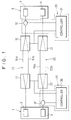
- FIG. 1 is a schematic diagram of an optical line switching system of the present invention;
- FIG. 2 is a characteristic diagram showing the change of intensity level of optical signal detected by each controller when the optical line is switched to the standby optical line by the optical line switching system; and
- FIG. 3 is a characteristic diagram showing the change of intensity level of optical signal detected by each controller when the standby optical line is switched to the original, optical line.
-
- One embodiment of the present invention will be described in detail below with reference to FIGS. 1 through 3.
- Although the optical line switching system is connected by many units, one unit being optical transmission line pairs consisting usually of two sets, a description of one unit is given below for simple explanation.
- In the unit of the optical line switching system of the present invention shown in Figure 1, a
first station 1 and a second station 5 are optically connected to each other by two sets of opticaltransmission line pairs transmission line pair 10 is provided withoptical swtiches transmission line pair 20 is likewise provided withoptical switches - The
first station 1 has a transmitter 2 and areceiver 3, and the second station 5 has a transmitter 6 and a receiver 7. The transmitters 2 and 6 send optical signals to be transmitted to the opticaltransmission line pairs transmission line pair 10, whereas thereceiver 3 to the transmitter 6 by means of the opticaltransmission line pair 20. - The optical
transmission line pair 10 includes anoptical line 10a and a standby optical bypath line 10b, and has control means 30 on the receiver 7 side. The control means 30 has acontroller 31 and aswitching device 32, and theswitching device 32 separates the optical signals sent through the opticaltransmission line pair 10 and sends the signals to the receiver 7 and thecontroller 31. - The optical
transmission line pair 20 is constructed in the same manner as the opticaltransmission line pair 10. It includes anoptical line 20a and a standbyoptical bypath line 20b, and is provided withcontrol means 35, having acontroller 36 and aswitching device 37, on thereceiver 3 side. Theswitching device 37 separates the optical signals sent through the opticaltransmission line pair 20 and sends the signals to thereceiver 3 and thecontroller 36. - For the
switching devices - The
controller 31 functions as an optical sensor which measures the light level of optical signal separated by theswitching device 32 and switches over theoptical switches transmission line pair 10 and the opticaltransmission line pair 20 and also as an electronic control unit (ECU) having a timer. Thecontroller 36, which also functions like thecontroller 31, switches over theoptical switch transmission line pair 10 and the opticaltransmission line pair 20. - The
optical switches optical switches controller - The optical line switching system of the present invention is configurated as described above, and when a failure such as broken line or abnormally increased loss occurs in the
optical line 10a, the optical line is switched as described below with reference to Figure 2. - It is assumed that a fault occurs in the
optical line 10a, and the intensity level L31 of optical signal which is separated by theswitching device 32 and detected by thecontroller 31 decreases to a level below the preset value Lop. - The
controller 31 monitors the intensity level of optical signal for a period H1 of time, checks that the decrease in intensity level of the optical signal is not a temporary phenomenon, and then outputs a switching signal to theoptical switches optical switches - As the result that the connection at the
optical switch 21 is changed, the optical signals which are separated by theswitching device 37 and sent to thecontroller 36 are cut off by theoptical switch 21, so that the intensity level L36 detected by thecontroller 36 becomes zero. - The
controller 36 judges the cutoff of optical signal to be an occurrence of fault after monitoring for a period H2 of time and outputs switching signals to theoptical switches - In this case, the
controller 36 is set by considering that theoptical switches optical switches - Thus, in FIG. 1, the path of optical signals transmitted from the transmitter 2 and the transmitter 6 to the receiver 7 and the
receiver 3, respectively, between the first andsecond stations 1,5 is changed from theoptical lines optical bypath line 10b and 20b. - To return the transmission lines of optical signal to the original
optical lines optical line 10a is corrected,optical switches controller 36, so that the connection is changed from the broken line to the solid line in FIG. 1. - This switching operation cuts off the transmission of optical signals between the
first station 1 and the second station 5; as a result, the intensity levels L31 and L36 of the optical signals which are monitored by thecontrollers - Then, the
controller 31 checks by monitoring for the period H3 of time as shown in FIG. 3 that the cutoff of optical signal caused by the switching operation is not a temporary phenomenon, and thereafter outputs switching signals to theoptical switches - This switches the transmission lines of optical signal transmitted between the
first station 1 and the second station 5 from the standbyoptical bypath lines 10b and 20b to the originaloptical lines - When the optical lines are switched, the
optical switches optical switches controllers - When the optical lines for optical signal are switched to the standby
optical bypath lines 10b and 20b because of a fault occurring in theoptical line 20a or a transfer due to hindrance of theoptical line 20a, too, the same operation as described above may be performed. - In the aforementioned optical line switching system, the number of repetitions of judgment is preset in the
controllers optical lines optical bypath lines 10b and 20b become faulty at the same time in each of opticaltransmission line pairs - In the embodiment of the switching system, description has been given of one unit consisting of two sets of optical
transmission line pairs controllers controllers transmission line pairs - Further, in the optical line switching system, when a fault is detected in any unit, the optical line of that unit only may be switched to the standby optical bypath line, or the optical lines of all units may be switched to the standby optical bypath lines.
Claims (4)
- An optical line switching system in which first and second stations (1 & 5), each of which has a signal transmitting means (2 & 6)for transmitting optical signals to be sent and a signal receiving means (3 & 7) for receiving optical signals sent from said signal transmitting means are provided, characterised in that the first and second stations are connected to each other by at least two sets of optical transmission line pairs (10 & 20), each set of which comprises an optical line (10a & 20a) and a standby optical bypath line (10b & 20b) and is provided with first and second optical switches (11 & 12, 21 & 22) at each end, so that the optical signals transmitted through said each optical transmission line pair can be switched from said optical line to said standby optical bypath line by said first and second optical switches provided in each of said optical transmission line pairs, and in that
first and second control means (30 & 35) are provided on the first and second station sides of said optical transmission line pairs respectively, which control means comprise means for detecting the transmitted optical signal and means (31 & 36) for switching over the optical switches of said two sets of optical transmission line pairs located on the station side of the respective control means in accordance with the light level of the detected optical signal; and wherein said first and second stations are connected by a plurality of units, one unit consisting of said two sets of optical transmission line pairs, and said first and second control means are used in common for the units. - An optical line switching system according to claim 1, wherein each of said first and second control means is provided with a controller (31, 36) and a switching device (32, 37).
- An optical line switching system according to claim 2, wherein said switching device is a light branching/coupling component.
- An optical line switching system according to claim 2, wherein said switching device is an optical component based on the local detection system.
Applications Claiming Priority (4)
| Application Number | Priority Date | Filing Date | Title |
|---|---|---|---|
| JP27414192 | 1992-10-13 | ||
| JP274141/92 | 1992-10-13 | ||
| JP27414192 | 1992-10-13 | ||
| PCT/JP1993/001464 WO1994009575A1 (en) | 1992-10-13 | 1993-10-12 | Light path switching system |
Publications (3)
| Publication Number | Publication Date |
|---|---|
| EP0617525A1 EP0617525A1 (en) | 1994-09-28 |
| EP0617525A4 EP0617525A4 (en) | 1995-03-08 |
| EP0617525B1 true EP0617525B1 (en) | 2000-05-17 |
Family
ID=17537599
Family Applications (1)
| Application Number | Title | Priority Date | Filing Date |
|---|---|---|---|
| EP93922067A Expired - Lifetime EP0617525B1 (en) | 1992-10-13 | 1993-10-12 | Light path switching system |
Country Status (4)
| Country | Link |
|---|---|
| EP (1) | EP0617525B1 (en) |
| KR (1) | KR100457134B1 (en) |
| CA (1) | CA2125692C (en) |
| WO (1) | WO1994009575A1 (en) |
Families Citing this family (10)
| Publication number | Priority date | Publication date | Assignee | Title |
|---|---|---|---|---|
| WO1999005802A1 (en) * | 1997-07-23 | 1999-02-04 | Adc Telecommunications, Inc. | Multiple-line proctection for telecommunications network |
| DE19734311A1 (en) * | 1997-08-08 | 1999-02-11 | Bosch Gmbh Robert | Arrangement for the transmission of optical signals with equivalent circuit effect |
| JP2003218793A (en) * | 2002-01-23 | 2003-07-31 | Ando Electric Co Ltd | Protection time variable optical line switching apparatus and optical transmission line redundancy system |
| JP2007336442A (en) * | 2006-06-19 | 2007-12-27 | Hitachi Communication Technologies Ltd | Center device, optical transmission system and system switching method |
| CN101114883B (en) * | 2007-07-27 | 2011-04-20 | 陕西迈克高新科技实业有限公司 | Self-cure type optical receiver |
| JP2012222555A (en) * | 2011-04-07 | 2012-11-12 | Mitsubishi Electric Corp | Optical transmission device |
| RU2485688C2 (en) * | 2011-08-09 | 2013-06-20 | Государственное казённое образовательное учреждение высшего профессионального образования Академия Федеральной службы охраны Российской Федерации (Академия ФСО России) | Method to transfer analogue signals along emergency digital fibre-optic transmission system and device that realises it |
| RU2483445C1 (en) * | 2011-12-02 | 2013-05-27 | Федеральное государственное бюджетное образовательное учреждение высшего профессионального образования "Казанский государственный энергетический университет" (ФГБОУ ВПО "КГЭУ") | System for wireless atmospheric optical communication at high electromagnetic interference facilities |
| WO2016035363A1 (en) * | 2014-09-01 | 2016-03-10 | オリンパス株式会社 | Optical communication system and endoscopic system |
| WO2017149814A1 (en) * | 2016-03-04 | 2017-09-08 | オリンパス株式会社 | Endoscope system and endoscope |
Family Cites Families (4)
| Publication number | Priority date | Publication date | Assignee | Title |
|---|---|---|---|---|
| JPS59151543A (en) * | 1983-02-08 | 1984-08-30 | Toshiba Corp | Optical communication system |
| JPS60144030A (en) * | 1983-12-30 | 1985-07-30 | Hitachi Ltd | Signal transmitting device of cargo handling equipment |
| JPS63152233A (en) * | 1986-12-17 | 1988-06-24 | Mitsubishi Electric Corp | Optical transmission equipment |
| JPS6460026A (en) * | 1987-08-31 | 1989-03-07 | Fujitsu Ltd | Transmission line switching device for communication equipment |
-
1993
- 1993-10-12 WO PCT/JP1993/001464 patent/WO1994009575A1/en active IP Right Grant
- 1993-10-12 KR KR1019940702026A patent/KR100457134B1/en not_active IP Right Cessation
- 1993-10-12 CA CA002125692A patent/CA2125692C/en not_active Expired - Fee Related
- 1993-10-12 EP EP93922067A patent/EP0617525B1/en not_active Expired - Lifetime
Also Published As
| Publication number | Publication date |
|---|---|
| KR940704092A (en) | 1994-12-12 |
| EP0617525A1 (en) | 1994-09-28 |
| KR100457134B1 (en) | 2005-02-07 |
| WO1994009575A1 (en) | 1994-04-28 |
| EP0617525A4 (en) | 1995-03-08 |
| CA2125692A1 (en) | 1994-04-28 |
| CA2125692C (en) | 2004-06-22 |
Similar Documents
| Publication | Publication Date | Title |
|---|---|---|
| US5069521A (en) | Optical transmission apparatus | |
| US6414768B1 (en) | Optical communication system | |
| US5781318A (en) | Circuit and method of testing for silent faults in a bi-directional optical communication system | |
| US5793481A (en) | System, method and device for monitoring a fiber optic cable | |
| EP0617525B1 (en) | Light path switching system | |
| EP1004184B1 (en) | Self-healing ring network and a method for fault detection and rectifying | |
| US6396602B1 (en) | Optical switching unit, particularly for switching to standby components in optical transmission systems | |
| US7457537B2 (en) | Optical telecommunication system with automatic channel switching | |
| CN115632703B (en) | Single-fiber bidirectional optical line protection system and optical line protection device | |
| JP3854372B2 (en) | Optical cross-connect device | |
| GB2175775A (en) | Data transmission system | |
| KR100333954B1 (en) | The Mehod and Apparatus of Dual Operation and Fault Detection in Optical Network Using Single Core | |
| US6650449B1 (en) | Method and device for network protection | |
| JPH07202805A (en) | Monitor system for optical fiber network | |
| JPH09312614A (en) | Optical interface automatic changeover system | |
| KR100939349B1 (en) | Automatic optical cross-connect apparatus using loop-back power monitoring | |
| KR200370399Y1 (en) | control system for optical cable | |
| JP3781523B2 (en) | Optical subscriber line transmission apparatus and standby optical transmission line monitoring method | |
| JP3440239B2 (en) | Line switching system for optical communication | |
| KR100528968B1 (en) | Apparatus and method for maintaining optical transmission system | |
| JPH04345219A (en) | Optical repeater station and optical terminal station | |
| JP2615762B2 (en) | Loop type optical transmission equipment | |
| JPH05284116A (en) | Data communication system and optical repeater device for the system | |
| JPS6052124A (en) | Route switching control system | |
| JPS61121546A (en) | Loop type optical transmitter |
Legal Events
| Date | Code | Title | Description |
|---|---|---|---|
| PUAI | Public reference made under article 153(3) epc to a published international application that has entered the european phase |
Free format text: ORIGINAL CODE: 0009012 |
|
| AK | Designated contracting states |
Kind code of ref document: A1 Designated state(s): GB IT |
|
| 17P | Request for examination filed |
Effective date: 19940929 |
|
| A4 | Supplementary search report drawn up and despatched |
Effective date: 19950119 |
|
| AK | Designated contracting states |
Kind code of ref document: A4 Designated state(s): GB IT |
|
| 17Q | First examination report despatched |
Effective date: 19971203 |
|
| GRAG | Despatch of communication of intention to grant |
Free format text: ORIGINAL CODE: EPIDOS AGRA |
|
| GRAG | Despatch of communication of intention to grant |
Free format text: ORIGINAL CODE: EPIDOS AGRA |
|
| GRAH | Despatch of communication of intention to grant a patent |
Free format text: ORIGINAL CODE: EPIDOS IGRA |
|
| GRAH | Despatch of communication of intention to grant a patent |
Free format text: ORIGINAL CODE: EPIDOS IGRA |
|
| GRAA | (expected) grant |
Free format text: ORIGINAL CODE: 0009210 |
|
| AK | Designated contracting states |
Kind code of ref document: B1 Designated state(s): GB IT |
|
| ITF | It: translation for a ep patent filed |
Owner name: ING. C. GREGORJ S.P.A. |
|
| EN | Fr: translation not filed | ||
| PLBE | No opposition filed within time limit |
Free format text: ORIGINAL CODE: 0009261 |
|
| STAA | Information on the status of an ep patent application or granted ep patent |
Free format text: STATUS: NO OPPOSITION FILED WITHIN TIME LIMIT |
|
| 26N | No opposition filed | ||
| REG | Reference to a national code |
Ref country code: GB Ref legal event code: IF02 |
|
| PGFP | Annual fee paid to national office [announced via postgrant information from national office to epo] |
Ref country code: GB Payment date: 20021009 Year of fee payment: 10 |
|
| PG25 | Lapsed in a contracting state [announced via postgrant information from national office to epo] |
Ref country code: GB Free format text: LAPSE BECAUSE OF NON-PAYMENT OF DUE FEES Effective date: 20031012 |
|
| GBPC | Gb: european patent ceased through non-payment of renewal fee |
Effective date: 20031012 |
|
| PG25 | Lapsed in a contracting state [announced via postgrant information from national office to epo] |
Ref country code: IT Free format text: LAPSE BECAUSE OF NON-PAYMENT OF DUE FEES;WARNING: LAPSES OF ITALIAN PATENTS WITH EFFECTIVE DATE BEFORE 2007 MAY HAVE OCCURRED AT ANY TIME BEFORE 2007. THE CORRECT EFFECTIVE DATE MAY BE DIFFERENT FROM THE ONE RECORDED. Effective date: 20051012 |