EP0615624B1 - Process for setting the transmission frequency in a distance measuring equipment working according to the echo-sounding principle - Google Patents
Process for setting the transmission frequency in a distance measuring equipment working according to the echo-sounding principle Download PDFInfo
- Publication number
- EP0615624B1 EP0615624B1 EP93920834A EP93920834A EP0615624B1 EP 0615624 B1 EP0615624 B1 EP 0615624B1 EP 93920834 A EP93920834 A EP 93920834A EP 93920834 A EP93920834 A EP 93920834A EP 0615624 B1 EP0615624 B1 EP 0615624B1
- Authority
- EP
- European Patent Office
- Prior art keywords
- frequency
- amplitude
- received signals
- transmission frequency
- sonic
- Prior art date
- Legal status (The legal status is an assumption and is not a legal conclusion. Google has not performed a legal analysis and makes no representation as to the accuracy of the status listed.)
- Expired - Lifetime
Links
Images

Classifications
-
- G—PHYSICS
- G01—MEASURING; TESTING
- G01S—RADIO DIRECTION-FINDING; RADIO NAVIGATION; DETERMINING DISTANCE OR VELOCITY BY USE OF RADIO WAVES; LOCATING OR PRESENCE-DETECTING BY USE OF THE REFLECTION OR RERADIATION OF RADIO WAVES; ANALOGOUS ARRANGEMENTS USING OTHER WAVES
- G01S15/00—Systems using the reflection or reradiation of acoustic waves, e.g. sonar systems
- G01S15/02—Systems using the reflection or reradiation of acoustic waves, e.g. sonar systems using reflection of acoustic waves
- G01S15/06—Systems determining the position data of a target
- G01S15/08—Systems for measuring distance only
- G01S15/10—Systems for measuring distance only using transmission of interrupted, pulse-modulated waves
- G01S15/102—Systems for measuring distance only using transmission of interrupted, pulse-modulated waves using transmission of pulses having some particular characteristics
- G01S15/107—Systems for measuring distance only using transmission of interrupted, pulse-modulated waves using transmission of pulses having some particular characteristics using frequency agility of carrier wave
-
- G—PHYSICS
- G01—MEASURING; TESTING
- G01S—RADIO DIRECTION-FINDING; RADIO NAVIGATION; DETERMINING DISTANCE OR VELOCITY BY USE OF RADIO WAVES; LOCATING OR PRESENCE-DETECTING BY USE OF THE REFLECTION OR RERADIATION OF RADIO WAVES; ANALOGOUS ARRANGEMENTS USING OTHER WAVES
- G01S7/00—Details of systems according to groups G01S13/00, G01S15/00, G01S17/00
- G01S7/52—Details of systems according to groups G01S13/00, G01S15/00, G01S17/00 of systems according to group G01S15/00
- G01S7/523—Details of pulse systems
- G01S7/526—Receivers
- G01S7/527—Extracting wanted echo signals
- G01S7/5273—Extracting wanted echo signals using digital techniques
Definitions
- the invention relates to a method for setting the transmission frequency in a range finder operating on the echo sounder principle, which has at least one electroacoustic transducer for emitting sound or ultrasound pulses and for converting received sound or ultrasound signals into electrical reception signals, and an oscillator with adjustable frequency for generation an electrical signal with the transmission frequency of the sound or ultrasound pulses to be emitted for the excitation of the electroacoustic transducer and an evaluation circuit for determining the transit time of the sound or ultrasound pulses as a measure of the distance of a measurement object, the optimum being obtained by analyzing received signals obtained for different transmission frequencies Transmitting frequency is determined and set in the oscillator.
- a method of this type is known from PCT publication WO 90/08966.
- PCT publication WO 90/08966 Compared to other known methods in which the transmission frequency to the resonance frequency of the Regulated electroacoustic transducer or controlled according to a known fixed temperature characteristic of the electroacoustic transducer as a function of the transducer temperature, it results in the advantage that the entire measuring chain consisting of transmitter, coupling to the acoustic space, path to the reflecting test object and back, and receiver in the determination the transmission frequency is included.
- the solutions described in this publication are limited to certain special cases.
- the most favorable overtone or undertone frequency with which the system is then operated is to be determined; or for the detection of echoes with a small signal / noise ratio, the parameters describing the noise are to be determined and the pulse shape and carrier frequency of the transmitted pulses are to be changed in accordance with these parameters.
- the analyzes are to be carried out or the parameters to be determined, or how the transmission frequency can be determined depending on the results achieved.
- the object of the invention is to provide a method of the type specified at the outset, which enables an analysis of the received signals in a simple manner with little circuit complexity, which immediately results in the optimal transmission frequency.
- this is achieved in that the amplitude-time profile of the received signals is formed and integrated during the analysis of the received signals in each receiving interval following the transmission of a sound or ultrasound pulse, that the integration values obtained for different transmitting frequencies are stored, and that the optimal transmission frequency in the oscillator is set to the frequency for which the maximum integration value is obtained.
- the fact can be advantageously used that it is increasingly common in newer methods for distance measurement according to the echo sounder principle to form the amplitude-time profile of the received signals and to evaluate them for determining the useful echo and for determining the running time of this useful echo.
- the devices available for this can also be used directly for the analysis of the received signals using the method according to the invention.
- the additional measures are then limited to integrating the amplitude-time profiles of the received signals received for different transmission frequencies and determining the transmission frequency for which the maximum integration value is obtained. These measures do not require any additional circuitry if they are implemented by suitable programming of the computer which forms the evaluation circuit in normal measuring operation. This is easily possible, since the analysis of the received signals to determine the optimal transmission frequency takes place in special frequency control intervals in which no distance measurement takes place. The frequency control intervals can be at longer intervals since the conditions for the optimal transmission frequency usually change only slowly.
- the method according to the invention also makes it possible in a simple manner to eliminate the influence of the noise on the analysis of the received signals if the noise level is so high that it impairs the determination of the optimal transmission frequency.
- the mean noise amplitude is determined and subtracted from the amplitude-time profile of the received signals before it is integrated. Since the noise is independent of the transmission frequency, the mean noise amplitude need only be determined once for each determination of the optimal transmission frequency.
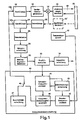
- the distance measuring device which operates on the echo sounder principle with sound or ultrasound pulses, the block diagram of which is shown in FIG. 1, contains an oscillator 10, the frequency of which can be adjusted by a frequency control signal SF supplied to its control input 10a.
- the output of the oscillator 10 is connected to a transmit pulse generator 12 which generates periodic electrical transmit pulses, the duration of which is short compared to the subsequent period of the transmit pulses and whose carrier frequency is the frequency generated by the oscillator 10.
- the transmit pulses are fed via a transceiver switch 14 to an electroacoustic transducer 16, which operates alternately as a transmit transducer and as a receive transducer.
- the converter 16 converts each transmission pulse supplied by the transmission pulse generator 12 into a sound or ultrasound pulse which is emitted by the converter 16 during a transmission interval.
- Each transmission interval is followed by a reception interval, in the course of which the converter 16 converts all sound or ultrasound signals received by it into electrical reception signals.
- These include, in particular, the sound or ultrasonic waves of the transmission pulse, which are reflected after passing through an acoustic path 18 on a measurement object 20, the distance of which is to be measured, or are reflected by interference points, but also external signals from other sources and natural vibrations of the transducer, in particular the reverberation of the Converter after the end of the transmission pulse.
- the duration of the reception interval must be greater than double the transit time of the sound or ultrasonic waves from the transducer 16 to the measurement object 20 at the greatest measurement distance occurring.
- the electrical reception signals emitted by the converter 16 during each reception interval are supplied to the input of an amplifier 22 via the transmission / reception switch 14.
- the transmit / receive switch 14 prevents the transmit pulses generated by the transmit pulse generator 12 from reaching the input of the amplifier 22 directly.
- the transducer 16 alternately as a transmit transducer and as a receive transducer, it is also possible to use it only as a transmit transducer and to provide a second electroacoustic transducer 16 'as a receive transducer, as indicated in broken lines in FIG. 1.
- the transceiver 14 and its connection to the amplifier 22 is omitted; instead, the input of amplifier 22 is connected to the output of receive converter 16 '.
- the received signals amplified by the amplifier 22 are transmitted via a narrowband band filter 24, the center frequency of which can be set by a control signal supplied to its control input 24a.
- the control input 24a of the bandpass filter 24 receives the same frequency control signal S F as the control input 10a of the oscillator 10, so that the center frequency of the bandpass filter 24 always corresponds exactly to the frequency of the oscillator 10 and thus to the frequency of the sound or ultrasound pulses sent by the transducer 16.
- the band filter 24 has the task of selecting the received signals with the frequency actually transmitted and suppressing all received signals with other frequencies.
- the received signals passed by the band filter 24 are demodulated in a demodulator 26.
- the demodulator 26 emits a signal at the output which corresponds to the envelope of the demodulated received signals.
- the demodulator 26 is followed by a sampling circuit 28 which, from the envelope signal in the course of each reception interval, produces a series of sampling values takes, which are preferably at the same time intervals. Each sample has the amplitude of the envelope signal at the time of sampling.
- An analog-to-digital converter 30 downstream of the sampling circuit 28 converts each sample into a digital code group which represents a number whose numerical value corresponds to the amplitude of the sample.
- the digital code groups supplied by the analog-digital converter 30 in the course of each reception interval are entered into a profile memory 32 and stored there. These stored code groups represent the amplitude-time profile of the received signals obtained during a receive interval and filtered by the band filter 24.
- An evaluation circuit 34 is connected to the profile memory 32 and has the task of recognizing the useful echo reflected on the measurement object 20 in the amplitude-time profile stored in the profile memory 32, determining the running time of the useful echo and, from this running time, the distance of the measurement object to calculate.
- Various solutions to this problem are known which are known to the person skilled in the art.
- a frequency control circuit 40 is connected to the profile memory 32 and outputs the frequency control signal S F at the output, which is fed to the control input 10 a of the oscillator 10.
- the frequency control circuit 40 contains the following circuits: an optimum frequency computer 41 connected to the profile memory 32; a replacement frequency calculator 42 connected to a temperature sensor 43 for measuring the temperature of the electroacoustic transducer 16; a decision circuit 45 which, based on information it receives from the optimum frequency calculator 41, decides whether an optimal frequency calculated by the optimum frequency calculator 41 or an equivalent frequency calculated by the substitute frequency calculator 42 is used for the generation of the frequency control signal SF in a frequency control signal generator 46; a tuning circuit 47; and a changeover switch 48 which, depending on its position, transmits either the frequency control signal S F generated by the frequency control signal generator 46 or a frequency control signal S F generated by the tuning circuit 47 to the oscillator 10.
- the frequency control circuit 40 is preferably formed by a microcomputer that is programmed to perform the functions of the circuits mentioned.
- the microcomputer which forms the evaluation circuit 34 in measurement mode can be used for this.
- the transmission frequency to be set in the oscillator 10 is determined in special frequency control intervals in which no distance measurement takes place. This takes advantage of the fact that the conditions relevant to the optimal transmission frequency change, if at all, only slowly, so that after a first determination of the optimal transmission frequency, it is sufficient to check them at larger intervals and to correct them if necessary.
- the changeover switch 48 is set such that the frequency control signal S F is supplied by the tuning circuit 47.
- the tuning circuit 47 causes a gradual change in the transmission frequency, starting from a starting frequency.
- a transmission pulse is emitted for each set frequency, and the received signals obtained for this transmission pulse are evaluated in the manner described later.
- the ratings obtained for the different frequencies are saved and compared with one another at the end of the frequency control interval.
- the frequency for which the best rating has been obtained is then used to generate the frequency control signal in the frequency control signal generator 46. If, in certain cases, it is not possible to determine an optimal transmission frequency by evaluating the received signals, the decision circuit 45 causes a replacement frequency calculated by the replacement frequency calculator 42 for the generation of the frequency control signal is used in the frequency control signal generator 46.
- the changeover switch 48 is brought into the other position, so that now the frequency control signal S F supplied by the frequency control signal generator 46 determines the transmission frequency set in the oscillator 10 until the next frequency control interval.
- the circuit block 50 represents a profile memory, in which the amplitude-time profiles of the received signals stored in the profile memory 32 are transmitted in sequence over the course of each frequency control interval.
- the circuit block 50 schematically shows an amplitude-time profile of received signals which were received in a receiving interval after the transmission of a transmission pulse with a transmission frequency determined by the tuning circuit 47.
- the solid curve is the envelope of the received signals, and the vertical lines represent the code groups A 1 , A 2 , ... A i , ..., A n of the digitized samples which have been taken from the envelope and are stored in the profile memory.
- Each code group represents a digital number, the numerical value of which corresponds to the amplitude of the envelope at the point in question.
- the amplitude-time profile stored in the profile memory 50 can be integrated directly if the noise level is so low that it does not appear to be a nuisance.
- An additional measure is shown in FIG. 2 which is applied at a higher noise level in order to eliminate the influence of the noise on the determination of the optimal transmission frequency. This measure consists in determining the mean noise amplitude and subtracting it from the amplitude-time profile of the received signals before it is integrated. Since the mean noise amplitude is independent of the transmission frequency and is not significant in the course of the frequency control interval changes, it is sufficient to determine them once at the beginning of each frequency control interval and to store them for the duration of the frequency control interval.
- the mean noise amplitude could be determined by measuring it in a time interval in which there are definitely only noise signals. Another possibility for determining the mean noise amplitude is shown in FIG. It consists in that the amplitude-time profile of the received signals is recorded in a receiving interval before which no transmit pulse has been transmitted, so that the received signals consist only of the noise signals. For better understanding, it is assumed in FIG. 2 that this amplitude-time profile is transferred to a second profile memory, which is represented by a circuit block 51. In the circuit block 51, the envelope obtained in this case and the code groups B 1 , B 2 ,..., B i , .., B n of the digitized samples of the envelope are stored in a manner similar to that in the circuit block 50. A mean value calculator 52 is connected to the profile memory 51 and calculates the mean value of the amplitude values stored in the profile memory 51; this is done by simply adding the numerical values represented by the stored code groups and dividing the sum by the number of code groups:
- the result B m is the mean value of the noise amplitude, which is stored in the form of a digital code group in the mean value calculator 52 and is available throughout the frequency control interval.
- the amplitude-time profile in the profile memory 50 is transferred to a profile memory 53, with the mean noise amplitude being subtracted from each stored amplitude value.
- Circuit block 53 also shows the envelope curve corresponding to these amplitude values, which corresponds to the difference between the amplitude-time profile of the received signals and the average noise amplitude.
- the transfer of the amplitude-time profile of the received signals into the profile memory 50 and the formation of the difference profile in the profile memory 53 is repeated for each transmission frequency f 1 , .., f i , .., f set by the tuning circuit 47 during a frequency control interval k .
- the formation of the amplitude-time profile of the noise signals in the profile memory 51 and the calculation of the average noise amplitude in the arithmetic circuit 52 are carried out only once at the beginning of each frequency control interval.
- an integrator 54 For each transmission frequency f i , an integrator 54 forms the integral of the amplitude-time profile in profile memory 53. This is done simply by summing the numerical values of the stored code groups:
- Each integration value D i obtained in this way is stored in a memory 55 together with the associated frequency f i .
- a maximum value detector 56 determines the largest value from the integration values D 1 .., D i , .., D k in the memory 55, and transmits the frequency f m assigned to this maximum integration value Dm to the frequency control signal generator 46 , which generates a frequency control signal S F , which causes the setting of the frequency f m as the optimal transmission frequency in the oscillator 10.
- the decision circuit 45 checks for each difference profile formed in the profile memory 53 whether it contains echo signals with sufficient amplitude values and whether there is a sufficiently large signal / noise ratio. As soon as one of these two conditions is not fulfilled for a difference profile, the decision circuit 45 blocks the calculation of the integration value by the integrator 54. It causes the calculation of a replacement frequency by the replacement frequency calculator 43 and ends the frequency control interval.
- the frequency control signal generator 46 generates a frequency control signal SF, which causes the setting of the substitute frequency as the transmission frequency in the oscillator. There are various options for calculating the replacement frequency, the choice of which is left to the specialist.
- the substitute frequency can be calculated on the basis of the temperature of the electroacoustic transducer measured by means of the temperature sensor 43 and a temperature characteristic of the transducer stored in the substitute frequency calculator. If, however, an optimal transmission frequency has already been determined beforehand, this earlier transmission frequency can be retained as a replacement frequency.
- the mean noise amplitude is zero.
- the difference profile formed in the profile memory 53 is identical to the amplitude-time profile in the profile memory 50, and the integrator 54 integrates this amplitude-time profile. It is therefore fundamentally possible, particularly in the case of low noise levels, to dispense with the determination and subtraction of the average noise level, which in the exemplary embodiment in FIG. 2 can be done simply by omitting circuits 51, 52 and 53.
- the decision circuit 45 determines on the basis of the determined signal-to-noise ratio whether the mean noise amplitude is determined and subtracted from the amplitude-time profile or not.
Landscapes
- Engineering & Computer Science (AREA)
- Physics & Mathematics (AREA)
- Radar, Positioning & Navigation (AREA)
- Remote Sensing (AREA)
- Computer Networks & Wireless Communication (AREA)
- General Physics & Mathematics (AREA)
- Acoustics & Sound (AREA)
- Measurement Of Velocity Or Position Using Acoustic Or Ultrasonic Waves (AREA)
- Measurement Of Radiation (AREA)
Abstract
Description
Die Erfindung betrifft ein Verfahren zur Einstellung der Sendefrequenz bei einem nach dem Echolotprinzip arbeitenden Entfernungsmeßgerät, das wenigstens einen elektroakustischen Wandler zur Aussendung von Schall- oder Ultraschallimpulsen und zur Umwandlung von empfangenen Schall- oder Ultraschallsignalen in elektrische Empfangssignale, einen in seiner Frequenz einstellbaren Oszillator zur Erzeugung eines elektrischen Signals mit der Sendefrequenz der auszusendenden Schall- oder Ultraschallimpulse für die Erregung des elektroakustischen Wandlers und eine Auswerteschaltung zur Ermittlung der Laufzeit der Schall- oder Ultraschallimpulse als Maß für die Entfernung eines Meßobjekts aufweist, wobei durch Analyse von für verschiedene Sendefrequenzen erhaltenen Empfangssignalen die optimale Sendefrequenz ermittelt und im Oszillator eingestellt wird.The invention relates to a method for setting the transmission frequency in a range finder operating on the echo sounder principle, which has at least one electroacoustic transducer for emitting sound or ultrasound pulses and for converting received sound or ultrasound signals into electrical reception signals, and an oscillator with adjustable frequency for generation an electrical signal with the transmission frequency of the sound or ultrasound pulses to be emitted for the excitation of the electroacoustic transducer and an evaluation circuit for determining the transit time of the sound or ultrasound pulses as a measure of the distance of a measurement object, the optimum being obtained by analyzing received signals obtained for different transmission frequencies Transmitting frequency is determined and set in the oscillator.
Ein Verfahren dieser Art ist aus der PCT-Veröffentlichung WO 90/08966 bekannt. Gegenüber anderen bekannten Verfahren, bei denen die Sendefrequenz auf die Resonanzfrequenz des elektroakustischen Wandlers geregelt oder nach einer bekannten festgelegten Temperaturkennlinie des elektroakustischen Wandlers in Abhängigkeit von der Wandlertemperatur gesteuert wird, ergibt es den Vorteil, daß die gesamte Meßkette bestehend aus Sender, Ankopplung an den akustischen Raum, Laufweg zum reflektierenden Meßobjekt und zurück sowie Empfänger in die Ermittlung der Sendefrequenz mit einbezogen wird. Die in dieser Veröffentlichung beschriebenen Lösungen sind jedoch auf bestimmte Sonderfälle beschränkt. So soll zur Detektion von Echos im Ausschwingbereich des elektroakustischen Wandlers durch Analyse des Verhaltens von Wandler und Empfänger bei Über- oder Untertonfrequenzen in einem bestimmten Frequenzbereich die günstigste Über- oder Untertonfrequenz ermittelt werden, mit der das System dann betrieben wird; oder zur Detektion von Echos bei kleinem Signal/Rausch-Abstand sollen die das Rauschen beschreibenden Parameter ermittelt und die Impulsform und Trägerfrequenz der Sendeimpulse gemäß diesen Parametern verändert werden. Es sind jedoch keine konkreten Lösungen angegeben, wie die Analysen durchgeführt oder die Parameter bestimmt werden sollen, oder wie die Sendefrequenz in Abhängigkeit von den erzielten Ergebnissen bestimmt werden kann.A method of this type is known from PCT publication WO 90/08966. Compared to other known methods in which the transmission frequency to the resonance frequency of the Regulated electroacoustic transducer or controlled according to a known fixed temperature characteristic of the electroacoustic transducer as a function of the transducer temperature, it results in the advantage that the entire measuring chain consisting of transmitter, coupling to the acoustic space, path to the reflecting test object and back, and receiver in the determination the transmission frequency is included. However, the solutions described in this publication are limited to certain special cases. Thus, for the detection of echoes in the swing-out range of the electroacoustic transducer by analyzing the behavior of transducer and receiver at overtone or undertone frequencies in a certain frequency range, the most favorable overtone or undertone frequency with which the system is then operated is to be determined; or for the detection of echoes with a small signal / noise ratio, the parameters describing the noise are to be determined and the pulse shape and carrier frequency of the transmitted pulses are to be changed in accordance with these parameters. However, no concrete solutions are given as to how the analyzes are to be carried out or the parameters to be determined, or how the transmission frequency can be determined depending on the results achieved.
Aus US-A-4 905 208 ist es bekannt, die optimale Sendefrequenz dadurch zu ermitteln, daß innerhalb eines bestimmten Frequenzbandes die Sendefrequenz schrittweise erhöht und die zugehörige Empfangsamplitude ermittelt wird. Die Sendefrequenz mit maximaler Empfangsamplitude wird dann ausgewählt.From US-A-4 905 208 it is known to determine the optimum transmission frequency by gradually increasing the transmission frequency within a certain frequency band and by determining the associated reception amplitude. The transmission frequency with maximum reception amplitude is then selected.
Aufgabe der Erfindung ist die Schaffung eines Verfahrens der eingangs angegebenen Art, das auf einfache Weise mit geringem Schaltungsaufwand eine Analyse der Empfangssignale ermöglicht, die unmittelbar die optimale Sendefrequenz ergibt.The object of the invention is to provide a method of the type specified at the outset, which enables an analysis of the received signals in a simple manner with little circuit complexity, which immediately results in the optimal transmission frequency.
Nach der Erfindung wird dies dadurch erreicht, daß während der Analyse der Empfangssignale in jedem auf die Aussendung eines Schall- oder Ultraschallimpulses folgenden Empfangsintervall das Amplituden-Zeit-Profil der Empfangssignale gebildet und integriert wird, daß die für verschiedene Sendefrequenzen erhaltenen Integrationswerte gespeichert werden, und daß als optimale Sendefrequenz im Oszillator die Frequenz eingestellt wird, für die der maximale Integrationswert erhalten wird.According to the invention, this is achieved in that the amplitude-time profile of the received signals is formed and integrated during the analysis of the received signals in each receiving interval following the transmission of a sound or ultrasound pulse, that the integration values obtained for different transmitting frequencies are stored, and that the optimal transmission frequency in the oscillator is set to the frequency for which the maximum integration value is obtained.
Bei dem erfindungsgemäßen Verfahren kann vorteilhaft die Tatsache ausgenutzt werden, daß es bei neueren Verfahren zur Entfernungsmessung nach dem Echolotprinzip zunehmend üblich ist, das Amplituden-Zeit-Profil der Empfangssignale zu bilden und zur Ermittlung des Nutzechos sowie zur Bestimmung der Laufzeit dieses Nutzechos auszuwerten. Die hierfür vorhandenen Einrichtungen können unmittelbar auch für die Analyse der Empfangssignale nach dem erfindungsgemäßen Verfahren verwendet werden. Die zusätzlichen Maßnahmen beschränken sich dann darauf, die Amplituden-Zeit-Profile der für verschiedene Sendefrequenzen erhaltenen Empfangssignale zu integrieren und die Sendefrequenz zu bestimmen, für die der maximale Integrationswert erhalten wird. Diese Maßnahmen erfordern keinen zusätzlichen Schaltungsaufwand, wenn sie durch geignete Programmierung des Computers realisiert werden, der im normalen Meßbetrieb die Auswerteschaltung bildet. Dies ist ohne weiteres möglich, da die Analyse der Empfangssignale zur Bestimmung der optimalen Sendefrequenz in besonderen Frequenzkontrollintervallen erfolgt, in denen keine Entfernungsmessung stattfindet. Die Frequenzkontrollintervalle können in größeren Zeitabständen liegen, da sich die Bedingungen für die optimale Sendefrequenz in der Regel nur langsam ändern.In the method according to the invention, the fact can be advantageously used that it is increasingly common in newer methods for distance measurement according to the echo sounder principle to form the amplitude-time profile of the received signals and to evaluate them for determining the useful echo and for determining the running time of this useful echo. The devices available for this can also be used directly for the analysis of the received signals using the method according to the invention. The additional measures are then limited to integrating the amplitude-time profiles of the received signals received for different transmission frequencies and determining the transmission frequency for which the maximum integration value is obtained. These measures do not require any additional circuitry if they are implemented by suitable programming of the computer which forms the evaluation circuit in normal measuring operation. This is easily possible, since the analysis of the received signals to determine the optimal transmission frequency takes place in special frequency control intervals in which no distance measurement takes place. The frequency control intervals can be at longer intervals since the conditions for the optimal transmission frequency usually change only slowly.
Das erfindungsgemäße Verfahren ermöglicht es auch auf einfache Weise, den Einfluß des Rauschens auf die Analyse der Empfangssignale zu eliminieren, wenn der Rauschpegel so groß ist, daß er die Ermittlung der optimalen Sendefrequenz beeinträchtigt. In diesem Fall wird gemäß einer vorteilhaften Weiterbildung des erfindungsgemäßen Verfahrens die mittlere Rauschamplitude ermittelt und von dem Amplituden-Zeit-Profil der Empfangssignale abgezogen, bevor dieses integriert wird. Da das Rauschen von der Sendefrequenz unabhängig ist, braucht die mittlere Rauschamplitude für jede Bestimmung der optimalen Sendefrequenz nur einmal ermittelt zu werden.The method according to the invention also makes it possible in a simple manner to eliminate the influence of the noise on the analysis of the received signals if the noise level is so high that it impairs the determination of the optimal transmission frequency. In this case, according to an advantageous development of the method according to the invention, the mean noise amplitude is determined and subtracted from the amplitude-time profile of the received signals before it is integrated. Since the noise is independent of the transmission frequency, the mean noise amplitude need only be determined once for each determination of the optimal transmission frequency.
Vorteilhafte Ausgestaltungen und Weiterbildungen der Erfindung sind in den Unteransprüchen gekennzeichnet.Advantageous refinements and developments of the invention are characterized in the subclaims.
Weitere Merkmale und Vorteile der Erfindung ergeben sich aus der folgenden Beschreibung eines Ausführungsbeispiels an Hand der Zeichnung. In der Zeichnung zeigen:
- Fig. 1
- das Blockschaltbild eines nach dem Echolotprinzip arbeitenden Entfernungsmeßgeräts, bei dem das erfindungsgemäße Verfahren angewendet wird, und
- Fig. 2
- ein detailliertes Blockschaltbild der im Entfernungsmeßgerät von Fig. 1 enthaltenen Frequenzsteuerschaltung.
- Fig. 1
- the block diagram of a working on the echo sounder principle, in which the inventive method is applied, and
- Fig. 2
- a detailed block diagram of the frequency control circuit included in the distance measuring device of FIG. 1.
Das nach dem Echolotprinzip mit Schall- oder Ultraschallimpulsen arbeitende Entfernungsmeßgerät, dessen Blockschaltbild in Fig. 1 dargestellt ist, enthält einen Oszillator 10, dessen Frequenz durch ein seinem Steuereingang 10a zugeführtes Frequenzsteuersignal SF einstellbar ist. Der Ausgang des Oszillators 10 ist mit einem Sendeimpulsgenerator 12 verbunden, der periodische elektrische Sendeimpulse erzeugt, deren Dauer kurz gegen die Folgeperiode der Sendeimpulse ist und deren Trägerfrequenz die vom Oszillator 10 erzeugte Frequenz ist. Die Sendeimpulse werden über eine Sende-Empfangsweiche 14 einem elektroakustischen Wandler 16 zugeführt, der abwechselnd als Sendewandler und als Empfangswandler arbeitet. Der Wandler 16 wandelt jeden vom Sendeimpulsgenerator 12 gelieferten Sendeimpuls in einen Schall- oder Ultraschallimpuls um, der während eines Sendeintervalls vom Wandler 16 abgestrahlt wird. An jedes Sendeintervall schließt sich ein Empfangsintervall an, in dessen Verlauf der Wandler 16 alle von ihm empfangenen Schall- oder Ultraschallsignale in elektrische Empfangssignale umwandelt. Hierzu gehören insbesondere die Schall- oder Ultraschallwellen des Sendeimpulses, die nach Durchlaufen eines akustischen Laufwegs 18 an einem Meßobjekt 20, dessen Entfernung gemessen werden soll, oder von Störstellen reflektiert werden, aber auch Fremdsignale von anderen Quellen sowie Eigenschwingungen des Wandlers, insbesonders das Nachschwingen des Wandlers nach dem Ende des Sendeimpulses. Die Dauer des Empfangsintervalls muss größer als die doppelte Laufzeit der Schall- oder Ultraschallwellen vom Wandler 16 zum Meßobjekt 20 bei der größten vorkommenden Meßentfernung sein.The distance measuring device, which operates on the echo sounder principle with sound or ultrasound pulses, the block diagram of which is shown in FIG. 1, contains an
Die vom Wandler 16 während jedes Empfangsintervalls abgegebenen elektrischen Empfangssignale werden über die Sende-Empfangsweiche 14 dem Eingang eines Verstärkers 22 zugeführt. Die Sende-Empfangsweiche 14 verhindert, daß die vom Sendeimpulsgenerator 12 erzeugten Sendeimpulse direkt zum Eingang des Verstärkers 22 gelangen. Anstatt den Wandler 16 abwechselnd als Sendewandler und als Empfangswandler zu betreiben, ist es auch möglich, ihn nur als Sendewandler zu verwenden und einen zweiten elektroakustischen Wandler 16' als Empfangswandler vorzusehen, wie in Fig. 1 in gestrichelten Linien angedeutet ist. In diesem Fall entfällt die Sende-Empfangsweiche 14 und deren Verbindung mit dem Verstärker 22; statt dessen ist der Eingang des Verstärkers 22 an den Ausgang des Empfangswandlers 16' angeschlossen.The electrical reception signals emitted by the
Die vom Verstärker 22 verstärkten Empfangssignale werden über ein schmalbandiges Bandfilter 24 übertragen, dessen Mittenfrequenz durch ein seinem Steuereingang 24a zugeführtes Steuersignal einstellbar ist. Der Steuereingang 24a des Bandfilters 24 empfängt das gleiche Frequenzsteuersignal SF wie der Steuereingang 10a des Oszillators 10, so daß die Mittenfrequenz des Bandfilters 24 immer exakt der Frequenz des Oszillators 10 und somit der Frequenz der vom Wandler 16 gesendeten Schall- oder Ultraschallimpulse entspricht. Das Bandfilter 24 hat die Aufgabe, die Empfangssignale mit der wirklich gesendeten Frequenz zu selektieren und alle Empfangssignale mit anderen Frequenzen zu unterdrücken.The received signals amplified by the
Die vom Bandfilter 24 durchgelassenen Empfangssignale werden in einem Demodulator 26 demoduliert. Der Demodulator 26 gibt am Ausgang ein Signal ab, das der Hüllkurve der demodulierten Empfangssignale entspricht. Dem Demodulator 26 ist eine Abtastschaltung 28 nachgeschaltet, die aus dem Hüllkurvensignal im Verlauf jedes Empfangsintervalls eine Reihe von Abtastwerten entnimmt, die vorzugsweise in gleichen Zeitabständen liegen. Jeder Abtastwert hat die Amplitude des Hüllkurvensignals im Abtastzeitpunkt. Ein der Abtastschaltung 28 nachgeschalteter Analog-Digital-Umsetzer 30 setzt jeden Abtastwert in eine digitale Codegruppe um, die eine Zahl darstellt, deren Zahlenwert der Amplitude des Abtastwerts entspricht. Die vom Analog-Digital-Umsetzer 30 im Verlauf jedes Empfangsintervalls gelieferten digitalen Codegruppen werden in einen Profilspeicher 32 eingegeben und dort gespeichert. Diese gespeicherten Codegruppen stellen das Amplituden-Zeit-Profil der während eines Empfangsintervalls erhaltenen und vom Bandfilter 24 gefilterten Empfangssignale dar.The received signals passed by the
Mit dem Profilspeicher 32 ist eine Auswerteschaltung 34 verbunden, die die Aufgabe hat, in dem im Profilspeicher 32 gespeicherten Amplituden-Zeit-Profil das am Meßobjekt 20 reflektierte Nutzecho zu erkennen, die Laufzeit des Nutzechos zu bestimmen und aus dieser Laufzeit die Entfernung des Meßobjekts zu berechnen. Es sind verschiedene Lösungen dieser Aufgabe bekannt, die dem Fachmann geläufig sind.An
Ferner ist mit dem Profilspeicher 32 eine Frequenzsteuerschaltung 40 verbunden, die am Ausgang das Frequenzsteuersignal SF abgibt, das dem Steuereingang 10a des Oszillators 10 zugeführt wird. Zum besseren Verständnis der Funktionsweise der Frequenzsteuerschaltung, die später an Hand von Fig. 2 erläutert wird, ist in Fig. 1 dargestellt, daß die Frequenzsteuerschaltung 40 die folgenden Schaltungen enthält: einen mit dem Profilspeicher 32 verbundenen Optimalfrequenzrechner 41; einen Ersatzfrequenzrechner 42, der mit einem Temperatursensor 43 zur Messung der Temperatur des elektroakustischen Wandlers 16 verbunden ist; eine Entscheidungsschaltung 45, die auf Grund von Informationen, die sie vom Optimalfrequenzrechner 41 empfängt, entscheidet, ob eine vom Optimalfrequenzrechner 41 berechnete optimale Frequenz oder eine vom Ersatzfrequenzrechner 42 berechnete Ersatzfrequenz für die Erzeugung des Frequenzsteuersignals SF in einem Frequenzsteuersignalerzeuger 46 verwendet wird; eine Durchstimmschaltung 47; und einen Umschalter 48, der je nach seiner Stellung entweder das vom Frequenzsteuersignalerzeuger 46 erzeugte Frequenzsteuersignal SF oder ein von der Durchstimmschaltung 47 erzeugtes Frequenzsteuersignal SF zum Oszillator 10 überträgt. Diese Schaltungen sind jedoch normalerweise in der Frequenzsteuerschaltung nicht konkret vorhanden; vielmehr ist die Frequenzsteuerschaltung 40 vorzugsweise durch einen Mikrocomputer gebildet, der so programmiert ist, daß er die Funktionen der erwähnten Schaltungen ausführt. Hierfür kann der Mikrocomputer verwendet werden, der im Meßbetrieb die Auswerteschaltung 34 bildet.Furthermore, a
Die Bestimmung der im Oszillator 10 einzustellenden Sendefrequenz erfolgt in besonderen Frequenzkontrollintervallen, in denen keine Entfernungsmessung stattfindet. Hierbei wird die Tatsache ausgenutzt, daß sich die für die optimale Sendefrequenz maßgeblichen Bedingungen, wenn überhaupt, nur langsam ändern, so daß es nach einer ersten Bestimmung der optimalen Sendefrequenz genügt, diese in größeren Zeitabständen zu überprüfen und gegebenenfalls zu korrigieren.The transmission frequency to be set in the
Während jedes Frequenzkontrollintervalls ist der Umschalter 48 so eingestellt, das das Frequenzsteuersignal SF von der Durchstimmschaltung 47 geliefert wird. Die Durchstimmschaltung 47 veranlaßt eine stufenweise Änderung der Sendefrequenz, ausgehend von einer Startfrequenz. Für jede eingestellte Frequenz wird ein Sendeimpuls ausgesendet, und die für diesen Sendeimpuls erhaltenen Empfangssignale werden in der später beschriebenen Weise bewertet. Die für die verschiedenen Frequenzen erhaltenen Bewertungen werden gespeichert und am Ende des Frequenzkontrollintervalls miteinander verglichen. Die Frequenz, für die die beste Bewertung erhalten worden ist, wird dann für die Erzeugung des Frequenzsteuersignals im Frequenzsteuersignalerzeuger 46 verwendet. Wenn es in bestimmten Fällen nicht möglich ist, eine optimale Sendefrequenz durch Bewertung der Empfangssignale zu ermitteln, veranlaßt die Entscheidungsschaltung 45, daß ersatzweise eine vom Ersatzfrequenzrechner 42 berechnete Ersatzfrequenz für die Erzeugung des Frequenzsteuersignals im Frequenzsteuersignalerzeuger 46 verwendet wird. Am Ende des Frequenzkontrollintervalls wird der Umschalter 48 in die andere Stellung gebracht, so daß nunmehr das vom Frequenzsteuersignalerzeuger 46 gelieferte Frequenzsteuersignal SF die im Oszillator 10 eingestellte Sendefrequenz bis zum nächsten Frequenzkontrollintervall bestimmt.During each frequency control interval, the
Die Funktionsweise des Frequenzsteuerschaltung 40 von Fig. 1 wird an Hand des detaillierten Blockschaltbilds von Fig. 2 erläutert. Der Schaltungsblock 50 repräsentiert einen Profilspeicher, in den im Verlauf jedes Frequenzkontrollintervalls der Reihe nach die im Profilspeicher 32 gespeicherten Amplituden-Zeit-Profile der Empfangssignale übertragen werden. Im Schaltungsblock 50 ist schematisch ein Amplituden-Zeit-Profil von Empfangssignalen dargestellt, die in einem Empfangsintervall nach der Aussendung eines Sendeimpulses mit einer durch die Durchstimmschaltung 47 bestimmten Sendefrequenz empfangen worden sind. Die durchgezogene Kurve ist die Hüllkurve der Empfangssignale, und die vertikalen Striche repräsentieren die im Profilspeicher gespeicherten Codegruppen A1, A2, ... Ai, ..., An der digitalisierten Abtastwerte, die aus der Hüllkurve entnommen worden sind. Jede Codegruppe stellt eine digitale Zahl dar, deren Zahlenwert der Amplitude der Hüllkurve an der betreffenden Stelle entspricht.The operation of the
Zur Ermittlung der optimalen Sendefrequenz kann das im Profilspeicher 50 gespeicherte Amplituden-Zeit-Profil unmittelbar integriert werden, wenn der Rauschpegel so niedrig ist, daß er nicht störend in Erscheinung tritt. In Fig. 2 ist eine zusätzliche Maßnahme dargestellt, die bei höherem Rauschpegel angewendet wird, um den Einfluß des Rauschens auf die Ermittlung der optimalen Sendefrequenz zu eliminieren. Diese Maßnahme besteht darin, die mittlere Rauschamplitude zu bestimmen und von dem Amplituden-Zeit-Profil der Empfangssignale zu subtrahieren, bevor dieses integriert wird. Da die mittlere Rauschamplitude von der Sendefrequenz unabhängig ist und sich im Verlauf des Frequenzkontrollintervalls nicht wesentlich ändert, genügt es, sie am Beginn jedes Frequenzkontrollintervalls einmal zu bestimmen und für die Dauer des Frequenzkontrollintervalls zu speichern. Die Bestimmung der mittleren Rauschamplitude könnte dadurch erfolgen, daß sie in einem Zeitintervall gemessen wird, in dem mit Sicherheit nur Rauschsignale vorhanden sind. In Fig. 2 ist eine andere Möglichkeit zur Bestimmung der mittleren Rauschamplitude dargestellt. Sie besteht darin, daß das Amplituden-Zeit-Profil der Empfangssignale in einem Empfangsintervall aufgenommen wird, vor dem kein Sendeimpuls ausgesendet worden ist, so daß die Empfangssignale nur aus den Rauschsignalen bestehen. Zum besseren Verständnis ist in Fig. 2 angenommen, daß dieses Amplituden-Zeit-Profil in einen zweiten Profilspeicher übertragen wird, der durch einen Schaltungsblock 51 repräsentiert ist. Im Schaltungsblock 51 sind in entsprechender Weise wie im Schaltungsblock 50 die in diesem Fall erhaltene Hüllkurve sowie die im Profilspeicher gespeicherten Codegruppen B1, B2, .., Bi, .., Bn der digitalisierten Abtastwerte der Hüllkurve dargestellt. Mit dem Profilspeicher 51 ist ein Mittelwert-Rechner 52 verbunden, der den Mittelwert der im Profilspeicher 51 gespeicherten Amplitudenwerte berechnet; dies geschieht durch einfache Addition der durch die gespeicherten Codegruppen dargestellten Zahlenwerte und Division der Summe durch die Anzahl der Codegruppen:![]()
![]()
Das Ergebnis Bm ist der Mittelwert der Rauschamplitude, der in Form einer digitalen Codegruppe im Mittelwert-Rechner 52 gespeichert wird und während des ganzen Frequenzkontrollintervalls zur Verfügung steht.The result B m is the mean value of the noise amplitude, which is stored in the form of a digital code group in the
Das im Profilspeicher 50 stehende Amplituden-Zeit-Profil wird in einen Profilspeicher 53 überführt, wobei gleichzeitig von jedem gespeicherten Amplitudenwert die mittlere Rauschamplitude abgezogen wird. Somit repräsentieren die im Profilspeicher 53 gespeicherten Codegruppen C1, C2 .., Ci, .., Cn die Amplitudenwerte![]()
![]()
Im Schaltungsblock 53 ist auch die diesen Amplitudenwerten entsprechende Hüllkurve dargestellt, die der Differenz zwischen dem Amplituden-Zeit-Profil der Empfangssignale und der mittleren Rauschamplitude entspricht.
Die Überführung des Amplituden-Zeit-Profils der Empfangssignale in den Profilspeicher 50 und die Bildung des Differenz-Profils im Profilspeicher 53 wiederholt sich für jede während eines Frequenzkontrollintervalls von der Durchstimmschaltung 47 eingestellte Sendefrequenz f1, .., fi, .., fk. Dagegen erfolgt die Bildung des Amplituden-Zeit-Profils der Rauschsignale im Profilspeicher 51 und die Berechnung der mittleren Rauschamplitude in der Rechenschaltung 52 nur einmal am Beginn jedes Frequenzkontrollintervalls.The transfer of the amplitude-time profile of the received signals into the
Für jede Sendefrequenz fi bildet ein Integrator 54 das Integral des im Profilspeicher 53 stehenden Amplituden-Zeit-Profils. Dies geschieht einfach durch Summierung der Zahlenwerte der gespeicherten Codegruppen:
Jeder auf diese Weise erhaltene Integrationswert Di wird zusammen mit der zugehörigen Frequenz fi in einem Speicher 55 gespeichert.Each integration value D i obtained in this way is stored in a
Am Ende jedes Frequenzkontrollintervalls ermittelt ein Maximalwertdetektor 56 unter den im Speicher 55 stehenden Integrationswerten D1 .., Di, .., Dk denjenigen mit dem größten Wert, und er überträgt die diesem maximalen Integrationswert Dm zugeordnete Frequenz fm zu dem Frequenzsteuersignalerzeuger 46, der ein Frequenzsteuersignal SF erzeugt, das im Oszillator 10 die Einstellung der Frequenz fm als optimale Sendefrequenz bewirkt.At the end of each frequency control interval, a
Diese Vorgänge laufen jedoch nur dann in der beschriebenen Weise ab, wenn sie von der Entscheidungsschaltung 45 zugelassen werden. Die Entscheidungsschaltung 45 prüft für jedes im Profilspeicher 53 gebildete Differenzprofil, ob dieses Echosignale mit ausreichenden Amplitudenwerten enthält und ob ein ausreichend großer Signal/Rausch-Abstand besteht. Sobald für ein Differenzprofil eine dieser beiden Bedingungen nicht erfüllt ist, blockiert die Entscheidungsschaltung 45 die Berechnung des Integrationswertes durch den Integrator 54. Sie veranlaßt die Berechnung einer Ersatzfrequenz durch den Ersatzfrequenzrechner 43 und beendet das Frequenzkontrollintervall. Der Frequenzsteuersignalerzeuger 46 erzeugt ein Frequenzsteuersignal SF, das im Oszillator die Einstellung der Ersatzfrequenz als Sendefrequenz bewirkt. Für die Berechnung der Ersatzfrequenz bestehen verschiedene Möglichkeiten, deren Wahl dem Fachmann überlassen bleibt. Wenn zuvor noch keine optimale Sendefrequenz ermittelt und eingestellt werden konnte, kann die Ersatzfrequenz auf Grund der mittels des Temperatursensors 43 gemessenen Temperatur des elektroakustischen Wandlers und einer im Ersatzfrequenzrechner gespeicherten Temperaturkennlinie des Wandlers berechnet werden. Wenn jedoch zuvor bereits eine optimale Sendefrequenz ermittelt worden ist, kann diese frühere Sendefrequenz als Ersatzfrequenz beibehalten werden.However, these processes only run in the described Refuse if they are allowed by
Wenn kein Rauschen vorhanden ist, ist die mittlere Rauschamplitude Null. In diesem Fall ist das im Profilspeicher 53 gebildete Differenzprofil mit dem Amplituden-Zeit-Profil im Profilspeicher 50 identisch, und der Integrator 54 integriert dieses Amplituden-Zeit-Profil. Es ist daher insbesondere bei niedrigen Rauschpegeln grundsätzlich möglich, auf die Ermittlung und Subtraktion des mittleren Rauschpegels zu verzichten, was bei dem Ausführungsbeispiel von Fig. 2 einfach dadurch geschehen kann, daß die Schaltungen 51, 52 und 53 fortgelassen werden. Eine andere Möglichkeit besteht darin, daß die Entscheidungsschaltung 45 auf Grund des ermittelten Signal/Rausch-Abstandes bestimmt, ob die mittlere Rauschamplitude ermittelt und von dem Amplituden-Zeit-Profil subtrahiert wird oder nicht.If there is no noise, the mean noise amplitude is zero. In this case, the difference profile formed in the
Claims (10)
- A process for setting the transmission frequency of a distance measuring instrument operating according to the echo-sounding principle, including at least one electro-acoustic transducer for emitting sonic or ultrasonic pulses and for converting received sonic or ultrasonic signals into electric received signals, a frequency-adjustable oscillator for generating an electric signal having the transmission frequency of the sonic or ultrasonic pulses which are to be transmitted for activating the electro-acoustic transducer, and an evaluation circuit for determining the travelling time of the sonic or ultrasonic pulses as a measure of the distance of a target object, the optimum transmission frequency being determined and tuned in the oscillator by analysing received signals obtained at different transmission frequencies, characterised in that during the analysis of the received signals in each reception interval following the emission of a sonic or ultrasonic pulse the amplitude-time-profile of the received signals is formed and integrated, that the integrated values obtained for different transmission frequencies are stored and that the frequency at which the maximum integrated value is attained is set in the oscillator as the optimum transmission frequency.
- A process according to claim 1, characterised in that the envelope of the received signals is scanned in order to form each amplitude-time-profile, that the scanned values are digitised and that the digitised scanned values are stored.
- A process according to claim 1 or 2, characterised in that the mean noise amplitude of the received signals is determined and that the difference between the amplitude-time-profile of the received signals and the mean noise amplitude is integrated.
- A process according to claim 3, characterised in that the noise amplitude of the received signals is determined at a time at which no echo signals attributable to a transmitted sonic or ultrasonic pulse are received.
- A process according to claim 3, characterised in that for determining the mean noise amplitude the amplitude-time-profile of the received signals is formed during a receiving interval prior to which no emission of a sonic or ultrasonic pulse has occurred, and that the mean amplitude values of the amplitude-time-profile are determined.
- A process according to any one of the preceding claims, characterised in that the received signals are passed through a band filter tuned to the frequency of the oscillator prior to the formation of the amplitude-time-profile.
- A process according to any one of the preceding claims, characterised in that the analysis of the received signals for the determination of the optimum transmission frequency is conducted during frequency control intervalls during which no distance measurement takes place.
- A process according to claim 7, characterised in that the transmission frequency is adjusted stepwise during each frequency control interval, within a predetermined frequency range commencing from a starting frequency.
- A process according to any one of the preceding claims, characterised in that a substitute frequency is set in the oscillator whenever the determination of an optimum transmission frequency by analysis of the received signals is not feasible.
- A process according to claim 9, characterised in that the substitute frequency is determined on the basis of a measurement of the temperature of the electro-acoustic transducer as a function of a given temperature characteristic of the transducer.
Applications Claiming Priority (3)
| Application Number | Priority Date | Filing Date | Title |
|---|---|---|---|
| DE4233257A DE4233257C1 (en) | 1992-10-02 | 1992-10-02 | |
| DE4233257 | 1992-10-02 | ||
| PCT/EP1993/002630 WO1994008252A1 (en) | 1992-10-02 | 1993-09-28 | Process for setting the transmission frequency in a distance measuring equipment working according to the echo-sounding principle |
Publications (2)
| Publication Number | Publication Date |
|---|---|
| EP0615624A1 EP0615624A1 (en) | 1994-09-21 |
| EP0615624B1 true EP0615624B1 (en) | 1996-11-06 |
Family
ID=6469539
Family Applications (1)
| Application Number | Title | Priority Date | Filing Date |
|---|---|---|---|
| EP93920834A Expired - Lifetime EP0615624B1 (en) | 1992-10-02 | 1993-09-28 | Process for setting the transmission frequency in a distance measuring equipment working according to the echo-sounding principle |
Country Status (10)
| Country | Link |
|---|---|
| US (1) | US5511041A (en) |
| EP (1) | EP0615624B1 (en) |
| JP (1) | JP2653389B2 (en) |
| AU (1) | AU660112B2 (en) |
| CA (1) | CA2124954C (en) |
| DE (1) | DE4233257C1 (en) |
| DK (1) | DK0615624T3 (en) |
| ES (1) | ES2096325T3 (en) |
| WO (1) | WO1994008252A1 (en) |
| ZA (1) | ZA937292B (en) |
Families Citing this family (28)
| Publication number | Priority date | Publication date | Assignee | Title |
|---|---|---|---|---|
| US5636179A (en) * | 1996-02-09 | 1997-06-03 | Iowa State University Research Foundation | Sonic spectrometer and treatment system |
| GB2339021A (en) * | 1998-06-30 | 2000-01-12 | Subacoustech Limited | Distance measuring systems and aircraft altimeters |
| US6397656B1 (en) * | 1999-01-25 | 2002-06-04 | Yamatake Corporation | System and method for detecting liquid serving as object to be detected in vessel using ultrasonic sensor |
| US6556511B1 (en) | 2001-11-01 | 2003-04-29 | Techno Research | Method of locking onto and tracking a target |
| JP3587466B2 (en) * | 2002-10-02 | 2004-11-10 | 三菱電機株式会社 | Vehicle periphery monitoring device |
| DE10323063A1 (en) * | 2003-05-20 | 2004-12-09 | Endress + Hauser Gmbh + Co. Kg | Level measurement procedure |
| US20050183346A1 (en) * | 2003-07-28 | 2005-08-25 | Dudley William E. | Air conditioning condensation drainage system |
| CN1598616A (en) * | 2003-09-18 | 2005-03-23 | 李翠瑚 | Pulse wave reflection oscillation device for measuring distance and its method |
| US7139220B2 (en) * | 2004-04-15 | 2006-11-21 | Siemens Milltronics Process Instruments Inc. | Dynamic filter tuning for pulse-echo ranging systems |
| US7287425B2 (en) * | 2004-05-17 | 2007-10-30 | Xtero Datacom Inc. | Ultrasonic fuel level monitoring device |
| US7245059B2 (en) * | 2004-05-17 | 2007-07-17 | Xtero Datacom Inc. | Method of exciting a piezoelectric crystal |
| DE102005038649B4 (en) * | 2005-08-16 | 2016-01-28 | Valeo Schalter Und Sensoren Gmbh | Method and system for operating an ultrasonic transducer |
| US20110002191A1 (en) * | 2006-12-07 | 2011-01-06 | Alion Science & Technology | Active sonar apparatuses and methods |
| US7905143B2 (en) * | 2007-07-23 | 2011-03-15 | Schmitt Measurement Systems, Inc. | Ultrasonic fuel level monitoring system incorporating an acoustic lens |
| EP2108976B1 (en) * | 2008-04-10 | 2012-10-03 | Siemens Aktiengesellschaft | Method of processing echo profile, and pulse-echo system for use with the method |
| US20100097891A1 (en) * | 2008-10-22 | 2010-04-22 | Nature Vision Inc. | Auto tune sonar system |
| US8104341B2 (en) * | 2009-03-25 | 2012-01-31 | Schmitt Measurement Systems, Inc. | Ultrasonic liquid level monitoring system |
| US8699299B2 (en) * | 2010-04-26 | 2014-04-15 | Semiconductor Components Industries, Llc | Self-tuning acoustic measurement system |
| US8416641B2 (en) * | 2010-04-28 | 2013-04-09 | Semiconductor Components Industries, Llc | Acoustic distance measurement system having cross talk immunity |
| US8412473B2 (en) | 2011-04-11 | 2013-04-02 | Schmitt Industries, Inc. | Event monitoring and detection in liquid level monitoring system |
| DE102012214047B4 (en) * | 2012-08-08 | 2023-05-11 | Robert Bosch Gmbh | Method for selecting an operating frequency range of an environment sensor device and corresponding environment sensor device |
| US10172002B2 (en) * | 2013-10-31 | 2019-01-01 | Tencent Technology (Shenzhen) Company Limited | Method and device for information transmission |
| EP3103191B1 (en) | 2014-02-07 | 2018-07-11 | The Regents of the University of California | Frequency tuning and/or frequency tracking of a mechanical system with low sensitivity to electrical feedthrough |
| US10179346B2 (en) | 2015-10-21 | 2019-01-15 | Semiconductor Components Industries, Llc | Method of forming a transducer controller and circuit therefor |
| US11194028B2 (en) | 2017-09-12 | 2021-12-07 | Semiconductor Components Industries, Llc | Measuring resonance parameters of piezoelectric transducers |
| US11269067B2 (en) | 2017-09-12 | 2022-03-08 | Semiconductor Components Industries, Llc | Response-based determination of piezoelectric transducer state |
| CN107884774B (en) * | 2017-12-01 | 2021-09-28 | 太原理工大学 | Multi-frequency anti-interference transformer-free driving ultrasonic ranging device |
| CN113933386A (en) * | 2020-07-13 | 2022-01-14 | 中国矿业大学(北京) | Ultrasonic pulse energy method for dynamically monitoring concrete damage |
Family Cites Families (5)
| Publication number | Priority date | Publication date | Assignee | Title |
|---|---|---|---|---|
| JPS6332386A (en) * | 1986-07-25 | 1988-02-12 | Honda Denshi Giken:Kk | Body sensing device using ultrasonic wave |
| US4905208A (en) | 1987-08-04 | 1990-02-27 | Interphase Technologies Inc. | Distance detecting apparatus |
| US4901245A (en) * | 1987-12-01 | 1990-02-13 | Moore Technologies, Inc. | Nonintrusive acoustic liquid level sensor |
| CH677834A5 (en) * | 1989-01-25 | 1991-06-28 | Grieshaber Ag | |
| WO1990008966A1 (en) * | 1989-02-02 | 1990-08-09 | Hawk Measurement Systems Pty. Limited | Ultrasonic distance measuring |
-
1992
- 1992-10-02 DE DE4233257A patent/DE4233257C1/de not_active Expired - Fee Related
-
1993
- 1993-09-28 WO PCT/EP1993/002630 patent/WO1994008252A1/en active IP Right Grant
- 1993-09-28 CA CA002124954A patent/CA2124954C/en not_active Expired - Fee Related
- 1993-09-28 US US08/244,592 patent/US5511041A/en not_active Expired - Fee Related
- 1993-09-28 ES ES93920834T patent/ES2096325T3/en not_active Expired - Lifetime
- 1993-09-28 EP EP93920834A patent/EP0615624B1/en not_active Expired - Lifetime
- 1993-09-28 JP JP6508693A patent/JP2653389B2/en not_active Expired - Lifetime
- 1993-09-28 AU AU48197/93A patent/AU660112B2/en not_active Ceased
- 1993-09-28 DK DK93920834.4T patent/DK0615624T3/en active
- 1993-10-01 ZA ZA937292A patent/ZA937292B/en unknown
Also Published As
| Publication number | Publication date |
|---|---|
| WO1994008252A1 (en) | 1994-04-14 |
| DE4233257C1 (en) | 1993-06-24 |
| CA2124954A1 (en) | 1994-04-14 |
| EP0615624A1 (en) | 1994-09-21 |
| AU4819793A (en) | 1994-04-26 |
| CA2124954C (en) | 1997-02-18 |
| ZA937292B (en) | 1994-04-22 |
| DK0615624T3 (en) | 1997-03-17 |
| US5511041A (en) | 1996-04-23 |
| JPH06511093A (en) | 1994-12-08 |
| AU660112B2 (en) | 1995-06-08 |
| JP2653389B2 (en) | 1997-09-17 |
| ES2096325T3 (en) | 1997-03-01 |
Similar Documents
| Publication | Publication Date | Title |
|---|---|---|
| EP0615624B1 (en) | Process for setting the transmission frequency in a distance measuring equipment working according to the echo-sounding principle | |
| EP0337293B1 (en) | Level measurement device | |
| DE2919335C2 (en) | Device for examining a solid with ultrasound | |
| EP0746775B1 (en) | Identification tag operating with acoustic surface waves | |
| EP0305780B1 (en) | Method and apparatus for error reduction in the measurement of the spatial movement of points to be measured by means of ultrasonic signals | |
| EP0452531A1 (en) | Electric measuring device for determining the propagation time of an electrical signal | |
| DE19509374C1 (en) | Adaptive optimisation method for ultrasound measurement signals | |
| EP0814348B1 (en) | Method for measuring the distance between a vehicle and an object | |
| EP0770886B1 (en) | Method and device for suppressing fixed target echoes during range measurement using the pulse time of flight principle | |
| DE2449037C3 (en) | Speed measuring device, in particular sound Doppler measuring device | |
| DE2513143C3 (en) | Speedometer | |
| EP0124897A2 (en) | Device for determining the transit time of ultrasonic pulses in a fluid | |
| DE3513270A1 (en) | Device for distance measurement, in particular for motor vehicles | |
| EP0935144B1 (en) | Evaluation concept for a range measurement method | |
| DE2817247C3 (en) | Arrangement for measuring distances, in particular for measuring water levels, by echo sounding in a gaseous medium by means of sound waves | |
| EP0369050B1 (en) | Method of suppression of interfering signals in the operation of an ultrasonic proximity switch | |
| DE19841154A1 (en) | Measurement of propagation time of sound waves; involves measuring phase shift between transmitted and received signals at two different frequencies | |
| DE102004035715B4 (en) | Sound propagation time measurement device | |
| EP0176931B1 (en) | Method for the measurement of the wall thickness of bodies by ultrasonic pulses, and device for carrying out the process | |
| EP1049945B1 (en) | Method for distance measurement and apparatus therefor | |
| DE3800800A1 (en) | Method and device for distance measurement (separation measurement) | |
| DE1904261C3 (en) | Doppler navigation arrangement | |
| DE3209838A1 (en) | Method and device for determining the wall thickness with the aid of ultrasonic pulses | |
| DE19901835A1 (en) | Self-tuning crystal notch filter for removing a signal of predefined frequency from an analogue reception signal in an ultrasonic imaging system | |
| CH456191A (en) | Process for measuring temperature and equipment for carrying out the process |
Legal Events
| Date | Code | Title | Description |
|---|---|---|---|
| PUAI | Public reference made under article 153(3) epc to a published international application that has entered the european phase |
Free format text: ORIGINAL CODE: 0009012 |
|
| 17P | Request for examination filed |
Effective date: 19940526 |
|
| AK | Designated contracting states |
Kind code of ref document: A1 Designated state(s): CH DK ES FR GB IT LI NL SE |
|
| GRAG | Despatch of communication of intention to grant |
Free format text: ORIGINAL CODE: EPIDOS AGRA |
|
| GRAH | Despatch of communication of intention to grant a patent |
Free format text: ORIGINAL CODE: EPIDOS IGRA |
|
| 17Q | First examination report despatched |
Effective date: 19960404 |
|
| GRAH | Despatch of communication of intention to grant a patent |
Free format text: ORIGINAL CODE: EPIDOS IGRA |
|
| GRAA | (expected) grant |
Free format text: ORIGINAL CODE: 0009210 |
|
| ITF | It: translation for a ep patent filed |
Owner name: BARZANO' E ZANARDO MILANO S.P.A. |
|
| AK | Designated contracting states |
Kind code of ref document: B1 Designated state(s): CH DK ES FR GB IT LI NL SE |
|
| REG | Reference to a national code |
Ref country code: CH Ref legal event code: NV Representative=s name: DIPL.-ING. VOLKER MORSTADT |
|
| ET | Fr: translation filed | ||
| GBT | Gb: translation of ep patent filed (gb section 77(6)(a)/1977) |
Effective date: 19970122 |
|
| REG | Reference to a national code |
Ref country code: ES Ref legal event code: FG2A Ref document number: 2096325 Country of ref document: ES Kind code of ref document: T3 |
|
| REG | Reference to a national code |
Ref country code: DK Ref legal event code: T3 |
|
| PLBE | No opposition filed within time limit |
Free format text: ORIGINAL CODE: 0009261 |
|
| STAA | Information on the status of an ep patent application or granted ep patent |
Free format text: STATUS: NO OPPOSITION FILED WITHIN TIME LIMIT |
|
| 26N | No opposition filed | ||
| PGFP | Annual fee paid to national office [announced via postgrant information from national office to epo] |
Ref country code: CH Payment date: 20000816 Year of fee payment: 8 |
|
| PGFP | Annual fee paid to national office [announced via postgrant information from national office to epo] |
Ref country code: NL Payment date: 20000824 Year of fee payment: 8 |
|
| PGFP | Annual fee paid to national office [announced via postgrant information from national office to epo] |
Ref country code: SE Payment date: 20000825 Year of fee payment: 8 Ref country code: DK Payment date: 20000825 Year of fee payment: 8 |
|
| PGFP | Annual fee paid to national office [announced via postgrant information from national office to epo] |
Ref country code: ES Payment date: 20000922 Year of fee payment: 8 |
|
| PG25 | Lapsed in a contracting state [announced via postgrant information from national office to epo] |
Ref country code: DK Free format text: LAPSE BECAUSE OF NON-PAYMENT OF DUE FEES Effective date: 20010928 |
|
| PG25 | Lapsed in a contracting state [announced via postgrant information from national office to epo] |
Ref country code: SE Free format text: LAPSE BECAUSE OF NON-PAYMENT OF DUE FEES Effective date: 20010929 Ref country code: ES Free format text: LAPSE BECAUSE OF NON-PAYMENT OF DUE FEES Effective date: 20010929 |
|
| PG25 | Lapsed in a contracting state [announced via postgrant information from national office to epo] |
Ref country code: LI Free format text: LAPSE BECAUSE OF NON-PAYMENT OF DUE FEES Effective date: 20010930 Ref country code: CH Free format text: LAPSE BECAUSE OF NON-PAYMENT OF DUE FEES Effective date: 20010930 |
|
| REG | Reference to a national code |
Ref country code: GB Ref legal event code: IF02 |
|
| PG25 | Lapsed in a contracting state [announced via postgrant information from national office to epo] |
Ref country code: NL Free format text: LAPSE BECAUSE OF NON-PAYMENT OF DUE FEES Effective date: 20020401 |
|
| EUG | Se: european patent has lapsed |
Ref document number: 93920834.4 |
|
| REG | Reference to a national code |
Ref country code: CH Ref legal event code: PL |
|
| NLV4 | Nl: lapsed or anulled due to non-payment of the annual fee |
Effective date: 20020401 |
|
| REG | Reference to a national code |
Ref country code: DK Ref legal event code: EBP |
|
| NLV4 | Nl: lapsed or anulled due to non-payment of the annual fee |
Effective date: 20020401 |
|
| REG | Reference to a national code |
Ref country code: ES Ref legal event code: FD2A Effective date: 20021011 |
|
| PGFP | Annual fee paid to national office [announced via postgrant information from national office to epo] |
Ref country code: FR Payment date: 20040910 Year of fee payment: 12 |
|
| PGFP | Annual fee paid to national office [announced via postgrant information from national office to epo] |
Ref country code: GB Payment date: 20040920 Year of fee payment: 12 |
|
| PG25 | Lapsed in a contracting state [announced via postgrant information from national office to epo] |
Ref country code: IT Free format text: LAPSE BECAUSE OF NON-PAYMENT OF DUE FEES;WARNING: LAPSES OF ITALIAN PATENTS WITH EFFECTIVE DATE BEFORE 2007 MAY HAVE OCCURRED AT ANY TIME BEFORE 2007. THE CORRECT EFFECTIVE DATE MAY BE DIFFERENT FROM THE ONE RECORDED. Effective date: 20050928 Ref country code: GB Free format text: LAPSE BECAUSE OF NON-PAYMENT OF DUE FEES Effective date: 20050928 |
|
| GBPC | Gb: european patent ceased through non-payment of renewal fee |
Effective date: 20050928 |
|
| PG25 | Lapsed in a contracting state [announced via postgrant information from national office to epo] |
Ref country code: FR Free format text: LAPSE BECAUSE OF NON-PAYMENT OF DUE FEES Effective date: 20060531 |
|
| REG | Reference to a national code |
Ref country code: FR Ref legal event code: ST Effective date: 20060531 |