EP0605750A1 - Coffee brewer with grinding device - Google Patents
Coffee brewer with grinding device Download PDFInfo
- Publication number
- EP0605750A1 EP0605750A1 EP93100231A EP93100231A EP0605750A1 EP 0605750 A1 EP0605750 A1 EP 0605750A1 EP 93100231 A EP93100231 A EP 93100231A EP 93100231 A EP93100231 A EP 93100231A EP 0605750 A1 EP0605750 A1 EP 0605750A1
- Authority
- EP
- European Patent Office
- Prior art keywords
- grinder
- coffee machine
- coffee
- machine according
- grinding
- Prior art date
- Legal status (The legal status is an assumption and is not a legal conclusion. Google has not performed a legal analysis and makes no representation as to the accuracy of the status listed.)
- Granted
Links
Images


Classifications
-
- A—HUMAN NECESSITIES
- A47—FURNITURE; DOMESTIC ARTICLES OR APPLIANCES; COFFEE MILLS; SPICE MILLS; SUCTION CLEANERS IN GENERAL
- A47J—KITCHEN EQUIPMENT; COFFEE MILLS; SPICE MILLS; APPARATUS FOR MAKING BEVERAGES
- A47J31/00—Apparatus for making beverages
- A47J31/42—Beverage-making apparatus with incorporated grinding or roasting means for coffee
-
- A—HUMAN NECESSITIES
- A47—FURNITURE; DOMESTIC ARTICLES OR APPLIANCES; COFFEE MILLS; SPICE MILLS; SUCTION CLEANERS IN GENERAL
- A47J—KITCHEN EQUIPMENT; COFFEE MILLS; SPICE MILLS; APPARATUS FOR MAKING BEVERAGES
- A47J31/00—Apparatus for making beverages
- A47J31/40—Beverage-making apparatus with dispensing means for adding a measured quantity of ingredients, e.g. coffee, water, sugar, cocoa, milk, tea
- A47J31/404—Powder dosing devices
-
- A—HUMAN NECESSITIES
- A47—FURNITURE; DOMESTIC ARTICLES OR APPLIANCES; COFFEE MILLS; SPICE MILLS; SUCTION CLEANERS IN GENERAL
- A47J—KITCHEN EQUIPMENT; COFFEE MILLS; SPICE MILLS; APPARATUS FOR MAKING BEVERAGES
- A47J42/00—Coffee mills; Spice mills
- A47J42/12—Coffee mills; Spice mills having grinding discs
-
- A—HUMAN NECESSITIES
- A47—FURNITURE; DOMESTIC ARTICLES OR APPLIANCES; COFFEE MILLS; SPICE MILLS; SUCTION CLEANERS IN GENERAL
- A47J—KITCHEN EQUIPMENT; COFFEE MILLS; SPICE MILLS; APPARATUS FOR MAKING BEVERAGES
- A47J42/00—Coffee mills; Spice mills
- A47J42/38—Parts or details
- A47J42/50—Supplying devices, e.g. funnels; Supply containers
-
- B—PERFORMING OPERATIONS; TRANSPORTING
- B02—CRUSHING, PULVERISING, OR DISINTEGRATING; PREPARATORY TREATMENT OF GRAIN FOR MILLING
- B02C—CRUSHING, PULVERISING, OR DISINTEGRATING IN GENERAL; MILLING GRAIN
- B02C7/00—Crushing or disintegrating by disc mills
- B02C7/18—Disc mills specially adapted for grain
- B02C7/188—Driving mechanisms
Definitions
- the invention relates to a coffee machine of the type explained in the preamble of claim 1.
- Such a coffee machine is known from EP-A-424 326.
- the known coffee machine is designed for preparing one or more types of coffee and has its own storage container and its own metering device for coffee beans for each type of coffee.
- a common mill is assigned to all storage containers.
- the mill has two toothed grinding disks arranged vertically one above the other, between which a horizontal grinding gap is formed.
- the upper grinding wheel is fixed, while the lower grinding wheel rotates around a vertical axis.
- the upper grinding disc has a filling opening in the region of the vertical axis of rotation, which opens into a receiving cavity formed between the two grinding discs and tapering towards the external grinding gap.
- the grinder is connected to a single brewing device via only one outlet opening for ground coffee.
- Each of the metering devices comprises a chamber with an upper opening through which the coffee beans fall into the chamber and a lateral opening through which the coffee beans can be ejected with a slide.
- the storage container corresponding to the desired type is opened and the desired dose of coffee beans is introduced into the metering chamber of the associated metering device.
- the storage container is closed again and the dose of coffee beans is ejected from the metering chamber with the aid of the slide so that they pass through the filling opening into the receiving cavity of the grinder. Due to the conically sloping bottom formation and rotating wings, the beans are directed towards the grinding gap, which narrows on the outside. They are grasped by the pre-breaker teeth deeply cut on the inside of the grinding rings and roughly divided.
- the grinding speed corresponds to the speed difference between the fixed upper and rotating lower grinding disc. In order to avoid excessive heating of the ground coffee and the associated loss of aroma, the grinding speed must not be too high.
- the pre-selected amount of ground coffee for a pre-selected portion of coffee drink in single-variety grinders is metered over the operating time of the grinder, with the coffee beans continuously sliding into the grinder, i.e. ground coffee is dosed, the grinder running until (after calibration) ) the predetermined amount of ground coffee has been dispensed.
- the coffee beans to be ground are pressed into the grinding gap by the weight of the following beans.
- the coffee beans In the known coffee machine, in which a single grinder has to grind different types of coffee, on the other hand, the coffee beans must be dosed and the grinder must be able to grind the metered amount of coffee beans to the very last rest, so that the receiving space before metering one second type of coffee is completely empty. This is achieved in the known coffee machine in that the grinder is put into operation before the coffee beans are poured in and continues to run for a certain time after grinding. However, even if it is possible to completely empty the receiving cavity in the known coffee machine, the grinding takes a very long time.
- the invention is therefore based on the object of providing a coffee machine with coffee bean dosing and a reduced brewing cycle time in a structurally simple manner.
- the accelerator is designed as a centrifugal force booster.
- This centrifugal booster works particularly effectively when the coffee beans are surrounded by rotating boundary surfaces in the feed area to the grinding gap.
- the design of the storage container according to claims 16 to 18 further reduces the access time to different types of coffee beans or the conveying time of the coffee beans into the grinder, and thus the duration of the brewing cycle. In addition, this simplifies the construction and, in the exemplary embodiment according to claim 17, creates the possibility for the customer to set the number of varieties and the storage quantity in accordance with his special wishes.
- the metering device described in claims 19 and 20 also ensures a short access time or short transport routes for the coffee beans.
- the time for a brewing cycle can be shortened further, since, for example, brewing can already take place in the second brewing device while the leached coffee grounds are removed from the first brewing device.
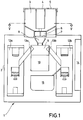
- FIG. 1 shows a schematic representation of a coffee machine 1 with a housing 2.
- a storage container 3 for sits on top of the housing 2 Coffee beans, which is covered with a rotatable lid 4, in which a closable fill opening 5 is formed.
- Below the storage container 3 there is a metering device 6 with an outlet opening 7.
- the outlet opening 7 opens into the interior of the housing 2 and is aligned with a filling funnel 8 of a coffee grinder 9, which can be driven by a motor 10.
- the coffee grinder 9 is connected via two output shafts 11a, 11b to a conventional brewing device 12a, 12b in such a way that the ground coffee in the coffee grinder 9 can optionally be transferred to the correspondingly assigned brewing device 12a, 12b.
- the discharge chutes 11a, 11b can be opened and closed on the mill 9 with a slide 13a, 13b, whereby the slide 13a, 13b, like the other method steps of the automatically running brewing cycle, can be actuated by a controller 14.
- a container 15 for the leached coffee grounds is also accommodated in the housing 2.
- the mill 9 contains a housing 16 which is pierced on opposite sides by substantially horizontally extending outlet openings 17a, 17b, which open into the discharge shafts 11a and 11b, respectively.
- a drive shaft 18 for driving a grinder 19 from the motor 10 enters the housing 16 from below.
- a lower grinder part in the form of a grinding disc 19a sits on the drive shaft 18.
- a second grinder part in the form of a grinding disc 19b is arranged above and coaxially with the grinding disc 19a, which forms a tapering grinding gap 20 and a receiving cavity 21 with the first grinding disc.
- the receiving cavity 21 protrudes through one upper grinding disk 19b extending filling opening 22 in connection with the filling funnel 8, wherein the upper grinding disk 19b extends to the filling opening 22.
- the filling funnel 8, the filling opening 22 and the grinder 19 with the grinder parts 19a, 19b, the grinding gap 20 and the receiving cavity 21 are formed coaxially with the drive shaft 18.
- a guide device in the form of a partially spherical guide body 23 extends further from below into the receiving cavity 21 as part of the lower grinder part 19a, which is also formed symmetrically to the axis of rotation of the drive shaft 18.
- the drive for the upper grinding disk 19b is derived from the drive shaft 18 via a reduction gear 24 with a series of gear wheels.
- the lower grinding disc 19a is driven at a speed which is far above the required grinding speed.
- the reduction is selected so that the second, upper grinding disc 19b is driven in the same direction as the first, lower grinding disc 19a, but at a speed which corresponds to the speed of the lower, first grinding disc 19a reduced by the grinding speed.
- the lower grinding disc 19a preferably rotates at 1400 rpm and the upper grinding disc 19b rotates at 400 to 700 rpm.
- the degree of fineness of the grinder 19 can also be regulated on the housing 16 via an adjusting thread 25.
- the coffee beans 26 falling into the receiving cavity 21 through the filling funnel 18 and the filling opening 22 first reach the rotating surface of the very rapidly rotating guide body 23 and experience there a rotational acceleration and are carried out into the grinding gap 20 by centrifugal forces. If they collide with the upper grinding disk 19b, they also experience a further rotational acceleration, so that the last falling beans 26 are also carried essentially directly through the grinding gap 20.
- the lower grinding disk 19a which rotates much faster than in conventional grinders, and the upper grinding disk 19b, which also rotates in the same direction, albeit at a lower speed, thus create an effective accelerator for the coffee beans, by means of which it is possible to dispense the pre-metered amount of coffee beans to grind in about the same time as would be possible if the filled coffee beans were under the pressure of subsequent coffee beans.
- a filling chute 26 is shown in FIG. 2, which opens into the funnel 8 for the filling of coffee beans by hand, for example for tastings or the like.
- the modified guide device 28 shown in FIGS. 3 and 4 can be provided.
- the guide device 28 contains a winged guide body 29 which, together with the rapidly rotating grinding disk 19a, is seated on the drive shaft 18 and has rotary blades 29a which are angled backwards against its direction of rotation.
- the rotary blades 29a are at a sufficiently large distance from one another that coffee beans 26 can fall between them. In the direction of the filling opening 22, all rotating blades 29a run in a guide tip out.
- the guide device 28 also has a guide ring 30 which extends around the filling opening 22 and rotates with the upper grinding disk 19b.
- the guide ring 30 has an approximately triangular cross section with an inwardly facing, rounded surface and a tip which extends into the receiving cavity 21 and is corrugated in the region 30a.
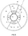
- the reservoir 3 is a substantially cylindrical side wall 31a and a funnel-shaped bottom 31b.
- the funnel-shaped bottom 31b ends at a likewise cylindrical inner wall 31c, which extends to the cover 4.
- Grooves 32 are provided both in the outer cylindrical wall 31a and in the inner cylindrical wall 31c, into which partitions 33 extending radially from the inside, of which only 4 partitions 33a, 33b, 33c and 33d are shown, can be inserted.
- the bottom 31b has outlet openings 34 in the vicinity of the inner cylindrical wall 31c, of which four outlet openings 34a, 34b, 34c, 34d are shown, which are evenly distributed around the circumference of the inner cylindrical wall 31c.
- the outlet openings can also be distributed unevenly.
- the storage container 3 can be divided into compartments 3a, 3b, 3c and 3d of four different sizes for four types of coffee beans. If required, more than four outlet openings can also be provided, and those which are not required can be closed by plugs or the like. Baffles that can be used can also be used in order to be asymmetrical to the assigned one Storage compartment arranged outlet opening to ensure the complete emptying of this compartment.
- the outlet openings 34 of the storage container 3 can optionally be connected to the metering device 6 shown in more detail in FIGS. 6 and 7.
- the metering device 6 has a housing 35 which is fixed relative to the storage container 3 and which is provided with the dispensing opening 7 of the metering device 6.
- at least one dosing chamber 37 is rotated about a vertical axis by means of a motor 36, which is expediently housed within the inner cylindrical wall 31c of the storage container 3.
- the metering chamber is open at the top and bottom, its entire cross section corresponding to the cross section of the outlet opening 7.
- a closing device 38 is arranged between the housing 35 and the outlet openings 34 of the storage container 3.
- the closing device 38 contains an upper disk 38a and a lower disk 38b, which are each provided with a passage opening 39a and 39b.
- the openings 39a, 39b are each arranged at the same distance from the center of the respective disks and are of the same size, their size also corresponding approximately to the size of the metering chamber 37.
- the two disks 38a, 38b are placed one on top of the other in such a way that their openings 39a, 39b are close to one another, but do not overlap. This position is fixed by a spring 40.
- Both disks 38a, 38b can be rotated together and coaxially with the metering chamber 37 relative to the storage container 3 via a stepper motor drive 41. Via a pull and push magnet 42, the two disks can also act against the force of the spring 40 are rotated relative to one another in such a way that their openings 39a, 39b are aligned with one another.
- the locking device 38 i.e. both disks 38a, 38b are rotated by means of the stepper motor drive 41 until the passage opening 39b of the lower disk 38b is aligned with the outlet opening 34 of the selected compartment of the storage container. Subsequently, with the help of the pull and push magnet 42, the upper disk 38a is rotated relative to the lower disk 38b against the force of the spring 40 so far that its passage opening 39a with the passage opening 39b and thus also with the outlet opening 34 of the selected compartment of the storage container 3 flees.
- the metering chamber 37 or a plurality of metering chambers 37 of predetermined size then moves under the aligned openings 34, 39a and 39b by actuating the motor 36, the metering chamber 37 is filled with the predetermined amount of coffee beans.
- the metering chamber 37 is rotated further, it passes through the outlet opening 7 so that the dose of coffee beans falls into the filling funnel 8 of the mill 9.
- FIGS. 8 and 9 A further exemplary embodiment of a mill 9 'is described in FIGS. 8 and 9, the same or comparable components being provided with the same reference symbols and not being explained again.
- the mill 9 ' is also arranged below a filling funnel 8 and contains a housing 16 which is pierced on opposite sides by substantially horizontal outlet openings, only one of the outlet openings 17a being shown.
- the outlet openings in FIG. 8 also open into the output shafts 11a and 11b.
- a drive shaft 18 from the motor 10 enters the housing 16 from below.
- a first grinder part 49a of a grinder 49 is seated on the drive shaft 18.
- the grinder part 49a contains a carrier 50 and a first grinding ring 51a fastened on the carrier 50 with the grinding surface facing upwards, and the one with a grinding surface facing downwards, forming a grinding gap 52 , arranged above it, the second grinding ring 51b.
- the second grinding ring 51b is fixedly connected to a second grinder part 49b, which in turn is arranged in the housing 16 such that it is not rotated by the drive shaft 18.
- the second grinder part 49b can be screwed more or less deeply into the housing 16 by means of a thread in order to adjust the size of the grinding gap 52.
- a filling opening 52 extends through the second grinder part 49b, which creates a connection between the filling funnel arranged above the housing 16 and the grinding gap 52 located below the filling funnel 8.
- a bean guide channel 53 is connected to the carrier 50 and thus to the drive shaft 18 and extends within the filling opening 52 from the filling funnel 8 to the grinding gap 52.
- the bean guide channel 53 has a rotationally symmetrical, approximately hat-shaped shape and contains an annular space 54, which is designed and arranged rotationally symmetrically to the axis of rotation of the drive shaft 18.
- the annular space 54 has a first region 54a, which extends essentially in a straight line and with a constant ring width between the filling funnel 8 and the carrier 50, the distance being, however of the annular space 54 increases from the axis of rotation of the drive shaft 18 from top to bottom.
- the first region 54a opens with a transition radius into a second region 54b which extends essentially radially outward with respect to the drive shaft 18 and from there into the grinding gap 52.
- the annular space 54 is delimited from the outside by an essentially hat-shaped wall and from the inside by a guide body 55 tapering upwards from the carrier 50.
- the guide body 55 can taper constantly upwards and end in a loosening shaft 55a.
- the two configurations of the traffic cone 55 are only entered together in FIG. 8 for reasons of clarity.
- annular space 54 is relatively narrow in order to ensure that the centrifugal force acts as freely as possible on each individual coffee bean. Of course, however, the annular space must be so large that the coffee beans cannot get stuck.
- the lower, radially outward-pointing region 54b of the bean guide channel 53 is connected to the grinding gap 52 via a plurality of circumferentially spaced openings 57 which each run obliquely against the conveying direction, in particular the lateral areas 57a of the openings 57 are designed as guide surfaces and guide the coffee beans 26 obliquely outwards.
- Each bean that comes out along the guide surface 57a into the area of the primary crushing teeth of the lower grinding disk, which are rotating at the same speed, is braked by contact with the upper, fixed grinding teeth. This results in an offset of the bean fragments formed in relation to the second area 54b of the annular space.
- the wall 57b opposite the guide surface 57a acts as a deflector if bean parts are reflected in the axial direction by the grinder.
- Projections 57c protruding into the grinding gap favor an additional conveying of the bean fragments in the direction of the outer grinding gap which shortens the grinding time.
- a uniform distribution of the coffee beans within the grinding chamber is achieved through the openings 57 and thus a good efficiency of the grinder is ensured.
- annular collecting space 58 for the ground coffee On the side of the grinding gap 52 facing away from the openings 57, as can be seen in FIGS. 8 and 9, there is an annular collecting space 58 for the ground coffee, the upper boundary surface of which is from the upper grinder part 49b and the lower boundary surface of which is from the rotating support 50 of the lower grinder part 49a is formed.
- Distribution vanes 59 are attached to the carrier 50 at a circumferential spacing and circulate with the carrier 50, sweep through the collecting space 58 and convey the coffee grounds collected therein through the outlet openings 17a to the outside.
- the metered-in coffee beans 26 in particular through the rotating bean guide channel 53 in the lower region of the annular space 54b, subjected to accelerating centrifugal forces which force the coffee beans to the grinding gap 52 and continuously.
- the centrifugal forces in the first region 54b also cause an obtuse impact angle of the beans on the moving walls of the annular space, as a result of which the throughput time of the beans between the filling funnel and the grinding gap is further reduced.
- the metering device described can also be used for other storage containers or in connection with other grinders.
- the storage container with its adjustable dividing walls is not necessarily to be used only in connection with the described dosing device or the described grinder.
- the locking device can be designed to be stationary and can be combined with a rotatable storage container, with only the respective outlet opening of the desired compartment of the storage container standing above the passage opening of the lower disk when the bean type is changed. Then the passage to the dosing chamber is opened by turning the upper disc.
- Coffee bean accelerators can also be used for grinders other than those shown. It is also possible to use the grinder designed according to the invention also for coffee machines with only one or with more than two brewing devices.
- the grinder according to the invention is also suitable for coffee machines that only brew one type of coffee, but in which a coffee bean dosage seems appropriate for other reasons.
Abstract
Description
Die Erfindung bezieht sich auf eine Kaffeemaschine der im Oberbegriff von Anspruch 1 erläuterten Art.The invention relates to a coffee machine of the type explained in the preamble of claim 1.
Eine derartige Kaffeemaschine ist aus der EP-A-424 326 bekannt. Die bekannte Kaffeemaschine ist zum Bereiten von einer oder mehreren Sorten Kaffee ausgelegt und weist für jede Kaffeesorte einen eigenen Vorratsbehälter und eine eigene Dosiereinrichtung für Kaffeebohnen auf. Allen Vorratsbehältern ist eine gemeinsame Mühle zugeordnet. Die Mühle weise zwei senkrecht übereinander angeordnete, gezähnte Mahlscheiben auf, zwischen denen ein horizontaler Mahlspalt ausgebildet ist. Die obere Mahlscheibe steht fest, während die untere Mahlscheibe um eine senkrechte Achse rotiert. Die obere Mahlscheibe weist im Bereich der senkrechten Drehachse eine Einfüllöffnung auf, die in einen zwischen beiden Mahlscheiben ausgebildeten und in Richtung auf den außenliegenden Mahlspalt spitz zulaufenden Aufnahmehohlraum mündet. Das Mahlwerk steht über jeweils nur eine Auslaßöffnung für Kaffeemehl mit einer einzigen Brüheinrichtung in Verbindung. Jede der Dosiereinrichtungen umfaßt eine Kammer mit einer oberen Öffnung, durch die die Kaffeebohnen in die Kammer fallen, und eine seitliche Öffnung, durch die die Kaffeebohnen mit einem Schieber ausgestoßen werden können.Such a coffee machine is known from EP-A-424 326. The known coffee machine is designed for preparing one or more types of coffee and has its own storage container and its own metering device for coffee beans for each type of coffee. A common mill is assigned to all storage containers. The mill has two toothed grinding disks arranged vertically one above the other, between which a horizontal grinding gap is formed. The upper grinding wheel is fixed, while the lower grinding wheel rotates around a vertical axis. The upper grinding disc has a filling opening in the region of the vertical axis of rotation, which opens into a receiving cavity formed between the two grinding discs and tapering towards the external grinding gap. The grinder is connected to a single brewing device via only one outlet opening for ground coffee. Each of the metering devices comprises a chamber with an upper opening through which the coffee beans fall into the chamber and a lateral opening through which the coffee beans can be ejected with a slide.
Im Betrieb der bekannten Kaffeemaschine wird der der gewünschten Sorte entsprechende Vorratsbehälter geöffnet und die gewünschte Dosis Kaffeebohnen in die Dosierkammer der zugeordneten Dosiereinrichtung eingebracht. Der Vorratsbehälter wird wieder verschlossen und die Dosis Kaffeebohnen mit Hilfe des Schiebers aus der Dosierkammer ausgestoßen, so daß sie durch die Einfüllöffnung in den Aufnahmehohlraum des Mahlwerks gelangen. Durch die konisch nach außen abfallende Bodenausbildung und mitdrehenden Flügeln werden die Bohnen in Richtung des sich außen verengenden Mahlspalts gelenkt. Sie werden von den an der Innenseite der Mahlringe tief eingeschnittenen Vorbrecherzähnen erfaßt und grob zerteilt. Soweit Bohnen oder Bohnenbruchstücke beim Aufprall auf einen rotierenden Zahn dabei eine Beschleunigung in Drehrichtung erfahren, werden sie in den zunehmend enger werdenden und mit größerer Zähneanzahl bestückten Mahlspalt getragen und dabei in immer feinere Teile zermahlen. Der äußerste Mahlspalt mit der größten Anzahl feinster Zähne bestimmt letztendlich die endgültige Mahlfeinheit. Die Mahlgeschwindigkeit entspricht der Drehzahldifferenz zwischen feststehender oberer und rotierender unterer Mahlscheibe. Um eine zu starke Erwärmung des Kaffeemehls und den damit verbundenen Aromaverlust zu vermeiden, darf jedoch die Mahlgeschwindigkeit nicht zu hoch sein.During operation of the known coffee machine, the storage container corresponding to the desired type is opened and the desired dose of coffee beans is introduced into the metering chamber of the associated metering device. The storage container is closed again and the dose of coffee beans is ejected from the metering chamber with the aid of the slide so that they pass through the filling opening into the receiving cavity of the grinder. Due to the conically sloping bottom formation and rotating wings, the beans are directed towards the grinding gap, which narrows on the outside. They are grasped by the pre-breaker teeth deeply cut on the inside of the grinding rings and roughly divided. Insofar as beans or bean fragments experience an acceleration in the direction of rotation when they impact a rotating tooth, they are carried in the increasingly narrow grinding gap with a larger number of teeth and thereby ground into ever finer parts. The outermost grinding gap with the largest number of finest teeth ultimately determines the final grinding fineness. The grinding speed corresponds to the speed difference between the fixed upper and rotating lower grinding disc. In order to avoid excessive heating of the ground coffee and the associated loss of aroma, the grinding speed must not be too high.
Normalerweise erfolgt die Dosierung der vorbestimmten Kaffeemehlmenge für eine vorgewählte Portion Kaffeegetränk bei Ein-Sorten-Mahlwerken über die Betriebsdauer des Mahlwerks, wobei die Kaffeebohnen laufend in das Mahlwerk nachrutschen, d.h. es wird Kaffeemehl dosiert, wobei das Mahlwerk solange läuft, bis (nach einer Eichung) die vorbestimmte Menge Kaffeemehl ausgegeben wurde. Dabei werden die jeweils zu mahlenden Kaffeebohnen durch das Gewicht der nachfolgenden Bohnen in den Mahlspalt gedrückt. Infolge des gefüllten Aufnahmehohlraums können weder ganze Bohnen noch Bohnenbruchstücke zur Drehachse hin ausweichen. Bei der bekannten Kaffeemaschine, bei der ein einziges Mahlwerk verschiedene Sorten Kaffee mahlen muß, müssen hingegen die Kaffeebohnen dosiert werden und das Mahlwerk muß in der Lage sein, die dosierte Menge Kaffeebohnen bis zum letzten Rest zu vermahlen, so daß der Aufnahmeraum vor dem Zudosieren einer zweiten Sorte Kaffee vollständig geleert ist. Dies wird bei der bekannten Kaffeemaschine dadurch erreicht, daß das Mahlwerk vor dem Einfüllen der Kaffeebohnen in Betrieb gesetzt wird und nach dem Vermahlen noch eine gewisse Zeit nachläuft. Selbst wenn jedoch das vollständige Leeren des Aufnahmehohlraums bei der bekannten Kaffeemaschine gelingt, dauert das Mahlen jedoch sehr lange. Dies liegt daran, daß insbesondere die letzten zu vermahlenden Kaffeebohnen oder Bohnenbruchstücke erst mehr oder weniger von den Zähnen und Wänden des Aufnahmehohlraums reflektiert werden, d.h. im Aufnahmehohlraum "herumspringen", bevor sie endgültig in den Mahlspalt gezogen werden. Eine längere Mahlzeit bedeutet jedoch auch eine längere Zeit zwischen dem Einleiten eines Brühzyklus und demjenigen Zeitpunkt, an dem das fertiggebrühte Getränk entnommen werden kann, was äußerst nachteilig ist.Normally, the pre-selected amount of ground coffee for a pre-selected portion of coffee drink in single-variety grinders is metered over the operating time of the grinder, with the coffee beans continuously sliding into the grinder, i.e. ground coffee is dosed, the grinder running until (after calibration) ) the predetermined amount of ground coffee has been dispensed. The coffee beans to be ground are pressed into the grinding gap by the weight of the following beans. As a result of the filled receiving cavity, neither whole beans nor bean fragments can dodge towards the axis of rotation. In the known coffee machine, in which a single grinder has to grind different types of coffee, on the other hand, the coffee beans must be dosed and the grinder must be able to grind the metered amount of coffee beans to the very last rest, so that the receiving space before metering one second type of coffee is completely empty. This is achieved in the known coffee machine in that the grinder is put into operation before the coffee beans are poured in and continues to run for a certain time after grinding. However, even if it is possible to completely empty the receiving cavity in the known coffee machine, the grinding takes a very long time. This is because, in particular, the last coffee beans or bean fragments to be ground are only more or less reflected by the teeth and walls of the receiving cavity, ie "jump" around in the receiving cavity before they are finally drawn into the grinding gap. However, a longer meal also means a longer time between the initiation of a brewing cycle and the time at which the finished brewed beverage can be removed, which is extremely disadvantageous.
Der Erfindung liegt somit die Aufgabe zugrunde, auf konstruktiv einfache Weise eine Kaffeemaschine mit Kaffeebohnendosierung und einer verringerten Brühzyklusdauer zu schaffen.The invention is therefore based on the object of providing a coffee machine with coffee bean dosing and a reduced brewing cycle time in a structurally simple manner.
Die Aufgabe wird durch die kennzeichnenden Merkmale des Anspruchs 1 gelöst.The object is achieved by the characterizing features of claim 1.
Durch den erfindungsgemäß vorgesehenen Beschleuniger wird auf konstruktiv einfache Weise auf die Bohnen ein zusätzlicher Druck ausgeübt, der sie zügig durch den Mahlspalt drückt. Das "Herumspringen" insbesondere der letzten Kaffeebohnen einer Dosiermenge im Aufnahmehohlraum wird dadurch vermieden.By the accelerator provided according to the invention additional pressure is exerted on the beans in a structurally simple manner, which presses them quickly through the grinding gap. The "jumping around" in particular of the last coffee beans of a dosage in the receiving cavity is avoided.
Besonders zweckmäßig und besonders schonend für die Kaffeebohnen ist es, wenn der Beschleuniger gemäß Anspruch 2 als Zentrifugalkraftverstärker ausgebildet ist.It is particularly expedient and particularly gentle for the coffee beans if the accelerator is designed as a centrifugal force booster.
Dieser Zentrifugalkraftverstärker arbeitet besonders effektiv, wenn die Kaffeebohnen gemäß Anspruch 3 im Zuführbereich zum Mahlspalt von rotierenden Begrenzungsflächen umgeben sind.This centrifugal booster works particularly effectively when the coffee beans are surrounded by rotating boundary surfaces in the feed area to the grinding gap.
Ein Ausführungsbeispiel eines Zentrifugalkraftbeschleunigers ist in den Ansprüchen 4 bis 9 beschrieben. Da in diesem Ausführungsbeispiel beide Mahlwerksteile angetrieben werden und sich die Mahlgeschwindigkeit somit aus der Differenz der beiden Geschwindigkeiten ergibt, kann zumindest eines der Mahlwerksteile mit einer gegenüber herkömmlichen Mahlwerken gleichen Typs wesentlich vergrößerten Geschwindigkeit umlaufen, so daß die auf die Kaffeebohnen einwirkenden Zentrifugalkräfte wesentlich erhöht werden können, ohne daß das Kaffeemehl durch eine zu hohe Mahlgeschwindigkeit unzulässig hoch erwärmt wird. Darüber hinaus erfährt die Kaffeebohne beim Aufprallen auf jedes der beiden Mahlwerksteile neben der Rückprallkraft gleichzeitig eine Drehbeschleunigung um die Rotationsachse. Diese bewirkt durch die gleichzeitig einwirkende Zentrifugalkraft einen stumpferen Abprallwinkel. Die Kaffeebohne springt nicht mehr im gesamten Aufnahmehohlraum hin und her, sondern bewegt sich weitgehend nur zwischen den beiden Mahlwerksteilen im spitz zulaufenden Teil des Aufnahmehohlraums, wobei sie rasch zum Mahlspalt gelangt.An embodiment of a centrifugal force accelerator is described in
Diese Bewegung der Kaffeebohnen kann noch durch verschiedene Leiteinrichtungen bzw. Leitkörper gemäß den Ansprüchen 7 bis 9 optimiert werden.This movement of the coffee beans can still be optimized by various guide devices or guide bodies according to
Eine weitere Ausgestaltung eines als Zentrifugalkraftversträkers ausgebildeten Beschleunigers ist in den Ansprüchen 10 bis 15 beschrieben.A further embodiment of an accelerator designed as a centrifugal force amplifier is described in
Durch die Ausgestaltung des Vorratsbehälters gemäß den Ansprüchen 16 bis 18 wird die Zugriffszeit zu verschiedenen Sorten Kaffeebohnen bzw. die Förderzeit der Kaffeebohnen in das Mahlwerk und somit die Dauer des Brühzyklus weiter verringert. Darüber hinaus wird dadurch die Konstruktion vereinfacht und, im Ausführungsbeispiel gemäß Anspruch 17, für den Kunden die Möglichkeit geschaffen, Sortenanzahl und Bevorratungsmenge gemäß seinen speziellen Wünschen einzustellen.The design of the storage container according to
Die in den Ansprüchen 19 und 20 beschriebene Dosiereinrichtung sorgt ebenfalls für eine kurze Zugrifffszeit bzw. kurze Transportwege für die Kaffeebohnen.The metering device described in
Durch die Ausgestaltung nach den Ansprüchen 21 und 22 kann die Zeit für einen Brühzyklus weiter verkürzt werden, da beispielsweise bereits in der zweiten Brüheinrichtung gebrüht werden kann, während der ausgelaugte Kaffeesatz aus der ersten Brüheinrichtung entfernt wird.Due to the configuration according to
Ausführungsbeispiele der Erfindung werden nachfolgend anhand der Zeichnungen näher erläutert. Es zeigt:
- Fig. 1
- eine schematische Darstellung einer erfindungsgemäßen Kaffeemaschine,
- Fig. 2
- einen Längsschnitt durch einen Teil der Kaffeemaschine aus Fig. 1,
- Fig. 3
- ein weiteres Ausführungsbeispiel eines Mahlwerks,
- Fig. 4
- die Draufsicht auf Fig. 3,
- Fig. 5
- den Schnitt V-V aus Fig. 1 in vergrößerter Darstellung,
- Fig. 6
- einen vergrößerten Längsschnitt durch die Dosiereinrichtung,
- Fig. 7
- eine Draufsicht auf die Dosiereinrichtung nach Fig. 6,
- Fig. 8
- einen Längsschnitt ähnlich Fig. 2 durch ein weiteres Ausführungsbeispiel, und
- Fig. 9
- den Schnitt IX-IX aus Fig. 8.
- Fig. 1
- 1 shows a schematic illustration of a coffee machine according to the invention,
- Fig. 2
- 2 shows a longitudinal section through part of the coffee machine from FIG. 1,
- Fig. 3
- another embodiment of a grinder,
- Fig. 4
- the top view of Fig. 3,
- Fig. 5
- 1 the section VV from FIG. 1 in an enlarged representation,
- Fig. 6
- an enlarged longitudinal section through the metering device,
- Fig. 7
- 6 shows a plan view of the metering device according to FIG. 6,
- Fig. 8
- a longitudinal section similar to FIG. 2 through another embodiment, and
- Fig. 9
- the section IX-IX of Fig. 8.
Aus Fig. 1 ist in schematischer Darstellung eine Kaffeemaschine 1 mit einem Gehäuse 2 ersichtlich. Oben auf dem Gehäuse 2 sitzt ein Vorratsbehälter 3 für Kaffeebohnen, der mit einem verdrehbaren Deckel 4 abgedeckt ist, in den eine verschließbare Einfüllöffnung 5 ausgebildet ist. Unterhalb des Vorratsbehälters 3 befindet sich eine Dosiereinrichtung 6 mit einer Austrittsöffnung 7. Die Austrittsöffnung 7 mündet in das Innere des Gehäuses 2 und fluchtet mit einem Einfülltrichter 8 einer Kaffeemühle 9, die durch einen Motor 10 angetrieben werden kann.1 shows a schematic representation of a coffee machine 1 with a
Die Kaffeemühle 9 steht über zwei Ausgabeschächte 11a, 11b mit jeweils einer herkömmlichen Brüheinrichtung 12a, 12b derart in Verbindung, daß das in der Kaffeemühle 9 gemahlene Kaffeemehl wahlweise in die entsprechend zugeordnete Brüheinrichtung 12a, 12b übergeleitet werden kann. Die Ausgabeschächte 11a, 11b sind an der Mühle 9 mit jeweils einem Schieber 13a, 13b zu öffnen und zu schließen, wobei die Schieber 13a, 13b, wie auch die übrigen Verfahrensschritte des automatisch ablaufenden Brühzyklus, über eine Steuerung 14 betätigt werden können. Im Gehäuse 2 ist weiterhin ein Behälter 15 für den ausgelaugten Kaffeesatz untergebracht.The
Wie Fig. 2 zeigt enthält die Mühle 9 ein Gehäuse 16, das an gegenüberliegenden Seiten durch im wesentlichen horizontal verlaufende Austrittsöffnungen 17a, 17b durchbrochen ist, die in die Ausgabeschächte 11a bzw. 11b münden. Von unten her tritt in das Gehäuse 16 eine Antriebswelle 18 zum Antrieb eines Mahlwerks 19 vom Motor 10 ein. Auf der Antriebswelle 18 sitzt ein unteres Mahlwerksteil in Form einer Mahlscheibe 19a. Oberhalb der Mahlscheibe 19a und koaxial mit ihr ist ein zweites Mahlwerksteil in Form einer Mahlscheibe 19b angeordnet, die mit der ersten Mahlscheibe einen spitz zulaufenden Mahlspalt 20 und einen Aufnahmehohlraum 21 bildet. Der Aufnahmehohlraum 21 steht über einen sich durch die obere Mahlscheibe 19b erstreckende Einfüllöffnung 22 mit dem Einfülltrichter 8 in Verbindung, wobei sich die obere Mahlscheibe 19b bis zur Einfüllöffnung 22 erstreckt. Der Einfülltrichter 8, die Einfüllöffnung 22 und das Mahlwerk 19 mit den Mahlwerksteilen 19a, 19b, dem Mahlspalt 20 und dem Aufnahmehohlraum 21 sind koaxial mit der Antriebswelle 18 ausgebildet.As shown in FIG. 2, the
In den Aufnahmehohlraum 21 erstreckt sich weiterhin von unten her eine Leiteinrichtung in Form eines teilkugelförmigen Leitkörpers 23 als Teil des unteren Mahlwerksteils 19a, der ebenfalls symmetrisch zur Drehachse der Antriebswelle 18 ausgebildet ist.A guide device in the form of a partially
Von der Antriebswelle 18 wird über ein Untersetzungsgetriebe 24 mit einer Reihe von Zahnrädern der Antrieb für die obere Mahlscheibe 19b abgeleitet. Dabei wird die untere Mahlscheibe 19a mit einer Geschwindigkeit angetrieben, die weit über der erforderlichen Mahlgeschwindigkeit liegt. Die Untersetzung ist so gewählt, daß die zweite, obere Mahlscheibe 19b gleichsinnig zur ersten, unteren Mahlscheibe 19a jedoch mit einer Geschwindigkeit angetrieben wird, die der um die Mahlgeschwindigkeit verringerten Geschwindigkeit der unteren, ersten Mahlscheibe 19a entspricht. Bevorzugt läuft die untere Mahlscheibe 19a mit 1400 U/min und die obere Mahlscheibe 19b mit 400 bis 700 U/min um. Am Gehäuse 16 kann weiterhin über ein Einstellgewinde 25 der Feinheitsgrad des Mahlwerks 19 reguliert werden.The drive for the
Die durch den Einfülltrichter 18 und die Einfüllöffnung 22 in den Aufnahmehohlraum 21 einfallenden Kaffeebohnen 26 gelangen zunächst auf die rotierende Oberfläche des sehr schnell rotierenden Leitkörpers 23, erfahren dort eine Drehbeschleunigung und werden durch Zentrifugalkräfte nach außen in den Mahlspalt 20 getragen. Falls sie an die obere Mahlscheibe 19b anprallen, erfahren sie auch dadurch eine weitere Drehbeschleunigung, so daß auch die letzten einfallenden Bohnen 26 im wesentlichen auf direktem Weg durch den Mahlspalt 20 getragen werden. Durch die wesentlich schneller als bei üblichen Mahlwerken umlaufende, untere Mahlscheibe 19a und die ebenfalls und gleichsinnig, wenn auch mit geringerer Geschwindigkeit, umlaufende, obere Mahlscheibe 19b wird somit ein wirksamer Beschleuniger für die Kaffeebohnen geschaffen, durch den es möglich ist, die vordosierte Menge Kaffeebohnen in etwa der gleichen Zeit zu mahlen, wie dies möglich wäre, wenn die eingefüllten Kaffeebohnen unter dem Druck nachfolgender Kaffeebohnen stehen würden.The
Zusätzlich zu der noch zu beschreibenden Dosiereinrichtung 6 ist in Fig. 2 eine Einfüllrutsche 26 gezeigt, die zum Einfüllen von Kaffeebohnen per Hand, beispielsweise für Verkostungen oder dgl., in den Trichter 8 mündet.In addition to the
Anstelle des teilkugelförmigen Leitkörpers 23 kann die in den Fig. 3 und 4 dargestellte, abgewandelte Leiteinrichtung 28 vorgesehen werden. Die Leiteinrichtung 28 enthält einen zusammen mit der schnell umlaufenden Mahlscheibe 19a auf der Antriebswelle 18 sitzenden, geflügelten Leitkörper 29, der entgegen seiner Drehrichtung nach hinten abgewinkelte Drehschaufeln 29a aufweist. Die Drehschaufeln 29a haben zueinander einen ausreichend großen Abstand, daß Kaffeebohnen 26 zwischen sie hineinfallen können. In Richtung auf die Einfüllöffnung 22 laufen alle Drehschaufeln 29a in einer Leitspitze aus. Die Leiteinrichtung 28 weist weiterhin einen Leitring 30 auf, der sich rund um die Einfüllöffnung 22 erstreckt und mit der oberen Mahlscheibe 19b umläuft. Der Leitring 30 hat einen etwa dreieckigen Querschnitt mit einer nach innen weisenden, abgerundeten Fläche und einer in den Aufnahmehohlraum 21 hineinreichenden Spitze, die im Bereich 30a geriffelt ist.Instead of the partially
Der Vorratsbehälter 3 ist, wie die Fig. 1 und 5 zeigen, eine im wesentlichen zylindrische Seitenwand 31a und einen trichterförmigen Boden 31b. Der trichterförmige Boden 31b endet an einer ebenfalls zylindrischen Innenwandung 31c, die sich bis zum Deckel 4 erstreckt. Sowohl in der äußeren zylindrischen Wandung 31a als auch in der inneren zylindrischen Wandung 31c sind Nuten 32 vorgesehen, in die radial von innen nach außen verlaufende Trennwände 33, von denen lediglich 4 Trennwände 33a, 33b, 33c und 33d dargestellt sind, eingeschoben werden können. Der Boden 31b weist in der Nähe der inneren zylindrischen Wandung 31c Austrittsöffnungen 34 auf, von denen vier Austrittsöffnungen 34a, 34b, 34c, 34d dargestellt sind, die gleichmäßig um den Umfang der inneren zylindrischen Wandung 31c verteilt sind. Wenn feststeht, daß eine oder mehrere der Kaffeesorten in größeren Mengen gebraucht werden wird, können die Austrittsöffnungen auch ungleichmäßig verteilt werden. Wie Fig. 5 zeigt, kann der Vorratsbehälter 3, je nach Anordnung der Trennwände 33, in stark unterschiedlich große Abteile 3a, 3b, 3c und 3d für vier Sorten Kaffeebohnen unterteilt werden. Bei Bedarf können auch mehr als vier Austrittsöffnungen vorgesehen und die jeweils nicht benötigten durch Stopfen oder dgl. verschlossen werden. Auch können einsetzbare Leitbleche verwendet werden, um auch bei einer assymmetrisch zum zugeordneten Vorratsbehälterabteil angeordnete Austrittsöffnung das vollständige Leeren dieses Abteils zu gewährleisten.1 and 5, the
Die Austrittsöffnungen 34 des Vorratsbehälters 3 können wahlweise mit der in den Fig. 6 und 7 näher dargestellten Dosiereinrichtung 6 in Verbindung gebracht werden. Die Dosiereinrichtung 6 weist ein relativ zum Vorratsbehälter 3 feststehendes Gehäuse 35 auf, das mit der Ausgabeöffnung 7 der Dosiereinrichtung 6 versehen ist. Im Inneren des Gehäuses 35 wird über einen Motor 36, der zweckmäßigerweise innerhalb der innere zylindrischen Wandung 31c des Vorratsbehälters 3 untergebracht ist, wenigstens eine Dosierkammer 37 um eine senkrechte Achse verdreht. Die Dosierkammer ist nach oben und unten offen, wobei ihr gesamter Querschnitt dem Querschnitt der Auslaßöffnung 7 entspricht. Zwischen dem Gehäuse 35 und den Auslaßöffnungen 34 des Vorratsbehälters 3 ist eine Schließeinrichtung 38 angeordnet. Die Schließeinrichtung 38 enthält eine obere Scheibe 38a und eine untere Scheibe 38b, die jeweils mit einer Durchlaßöffnung 39a bzw. 39b versehen sind. Die Öffnungen 39a, 39b sind jeweils im gleichen Abstand zur Mitte der jeweiligen Scheiben angeordnet und gleich groß, wobei ihre Größe auch etwa der Größe der Dosierkammer 37 entspricht. In Normalstellung sind die beiden Scheiben 38a, 38b derart aufeinandergelegt, daß ihre Öffnungen 39a, 39b nahe beieinander liegen, sich jedoch nicht überlappen. Diese Stellung ist durch eine Feder 40 fixiert.The
Beide Scheiben 38a, 38b können über einen Schrittmotorantrieb 41 gemeinsam und koaxial mit der Dosierkammer 37 relativ zum Vorratsbehälter 3 verdreht werden. Über einen Zug- und Druckmagneten 42 können die beiden Scheiben gegen die Kraft der Feder 40 aber auch relativ zueinander derart verdreht werden, daß ihre Öffnungen 39a, 39b miteinander fluchten.Both
Soll eine bestimmte Sorte Kaffeebohnen aus einem der Abteile 3a bis 3d des Vorratsbehälters 3 dosiert werden, so wird zunächst die Schließeinrichtung 38, d.h. beide Scheiben 38a, 38b, mit Hilfe des Schrittmotorantriebs 41 so weit verdreht, bis die Durchlaßöffnung 39b der unteren Scheibe 38b mit der Auslaßöffnung 34 des ausgewählten Abteils des Vorratsbehälters fluchtet. Anschließend wird mit Hilfe des Zug- und Druckmagnets 42 die obere Scheibe 38a relativ zur unteren Scheibe 38b gegen die Kraft der Feder 40 so weit verdreht, daß ihre Durchlaßöffnung 39a mit der Durchlaßöffnung 39b und damit auch mit der Auslaßöffnung 34 des ausgewählten Abteils des Vorratsbehälters 3 fluchtet. Bewegt sich dann durch Betätigen des Motors 36 die Dosierkammer 37 bzw. eine Mehrzahl Dosierkammern 37 vorbestimmter Größe unter die fluchtenden Öffnungen 34, 39a und 39b, so wird die Dosierkammer 37 mit der vorbestimmten Menge Kaffeebohnen gefüllt. Beim weiteren Verdrehen der Dosierkammer 37 gelangt diese über die Auslaßöffnung 7, so daß die Kaffeebohnendosis in den Einfülltrichter 8 der Mühle 9 fällt.If a certain type of coffee beans is to be dosed from one of the
In den Fig. 8 und 9 ist ein weiteres Ausführungsbeispiel einer Mühle 9' beschrieben, wobei gleiche bzw. vergleichbare Bauteile mit den gleichen Bezugszeichen versehen und nicht nochmals erläutert sind. Auch die Mühle 9' ist unterhalb eines Einfülltrichters 8 angeordnet und enthält ein Gehäuse 16, das an gegenüberliegenden Seiten durch im wesentlichen horizontal verlaufende Austrittsöffnungen durchbrochen ist, wobei lediglich eine der Austrittsöffnungen 17a gezeigt ist. Auch die Austrittsöffnungen der Fig. 8 münden in die Ausgabeschächte 11a bzw. 11b. In das Gehäuse 16 tritt von unten her eine Antriebswelle 18 vom Motor 10 ein.A further exemplary embodiment of a mill 9 'is described in FIGS. 8 and 9, the same or comparable components being provided with the same reference symbols and not being explained again. The mill 9 'is also arranged below a filling
Auf der Antriebswelle 18 sitzt ein erstes Mahlwerksteil 49a eines Mahlwerks 49. Das Mahlwerksteil 49a enthält einen Träger 50 und einen ersten, mit nach oben weisender Mahlfläche auf dem Träger 50 befestigten Mahlring 51a, dem ein mit nach unten weisender Mahlfläche, unter Ausbildung eines Mahlspaltes 52, senkrecht darüber angeordneter, zweiter Mahlring 51b gegenüberliegt. Der zweite Mahlring 51b ist fest mit einem zweiten Mahlwerksteil 49b verbunden, das wiederum im Gehäuse 16 derart angeordnet ist, daß es von der Antriebswelle 18 nicht verdreht wird. Das zweite Mahlwerksteil 49b kann jedoch über ein Gewinde mehr oder weniger tief in das Gehäuse 16 eingeschraubt werden, um die Größe des Mahlspaltes 52 einzustellen. Durch das zweite Mahlwerksteil 49b erstreckt sich eine Einfüllöffnung 52, die eine Verbindung zwischen dem oberhalb des Gehäuses 16 angeordneten Einfülltrichter und dem unterhalb des Einfülltrichters 8 befindlichen Mahlspalt 52 herstellt.A
Mit dem Träger 50 und damit mit der Antriebswelle 18 ist ein Bohnenleitkanal 53 verbunden, der sich innerhalb der Einfüllöffnung 52 vom Einfülltrichter 8 zum Mahlspalt 52 erstreckt. Der Bohnenleitkanal 53 hat eine rotationssymmetrische, etwa hutförmige Gestalt und enthält einen Ringraum 54, der rotationssymmetrisch zur Drehachse der Antriebswelle 18 ausgebildet und angeordnet ist. Der Ringraum 54 weist einen ersten Bereich 54a auf, der sich im wesentlichen geradlinig und mit konstanter Ringweite zwischen dem Einfülltrichter 8 und dem Träger 50 erstreckt, wobei jedoch der Abstand des Ringraums 54 von der Drehachse der Antriebswelle 18 von oben nach unten zunimmt. Der erste Bereich 54a mündet mit einem Übergangsradius in einen sich im wesentlichen bezüglich der Antriebswelle 18 radial nach außen erstreckenden, zweiten Bereich 54b und von dort in den Mahlspalt 52.A
Der Ringraum 54 wird von außen durch eine im wesentlichen hutförmige Wandung und von innen durch einen vom Träger 50 nach oben hin spitz zulaufenden Leitkörper 55 begrenzt. Der Leitkörper 55 kann, wie in Fig. 8 auf der linken Seite gezeichnet, sich nach oben hin konstant verjüngen und in einer Lockerungswelle 55a auslaufen. Es ist jedoch auch möglich, wie auf der rechten Seite der Fig. 8 gezeigt, den Leitkörper 55 mit einem die Kaffeebohnen 26 nach außen abweisenden, rotätionssymmetrischen Leitvorsprung 56 zu versehen. Durch den im oberen Bereich des Bohnenleitkanals 53 angeordneten Leitvorsprung werden die Kaffeebohnen 26 frühzeitig nach außen abgelenkt und in Rotation um die Antriebsachse versetzt. Selbstverständlich sind die beiden Ausgestaltungen des Leitkegels 55 nur aus Gründen der Übersichtlichkeit gemeinsam in Fig. 8 eingetragen.The
Darüber hinaus ist der Ringraum 54 relativ eng, um eine möglichst ungehinderte Einwirkung der Zentrifugalkraft auf jede einzelne Kaffeebohne sicherzustellen. Selbstverständlich muß der Ringraum jedoch so groß sein, daß die Kaffeebohnen nicht hähgenbleiben können.In addition, the
Der untere, radial nach außen weisende Bereich 54b des Bohnenleitkanals 53 steht mit dem Mahlspalt 52 über eine Mehrzahl im Umfangsabstand zueinander angeordneter Öffnungen 57 in Verbindung, die jeweils entgegen Förderrrichtung schräg verlaufen, wobei insbesondere die seitlichen Bereiche 57a der Öffnungen 57 als Leitflächen ausgebildet sind und die Kaffeebohnen 26 schräg nach außen leiten. Jede Bohne, die entlang der Leitfläche 57a nach außen in den Bereich der mit gleicher Drehzahl mitlaufenden Vorbrechzähne der unteren Mahlscheibe gelangt, wird durch die Berührung mit den oberen, feststehenden Mahlzähnen abgebremst. Daraus resultiert ein Versatz der entstandenen Bohnenbruchstücke gegenüber dem zweiten Bereich 54b des Ringraums. Insbesondere bei stark schräg verlaufender Bohrung wirkt die der leitfläche 57a gegenüberliegende Wandung 57b als Abweise, falls Bohnenteile vom Mahlwerk in Achsrichtung reflektiert werden. In den Mahlspalt ragende Vorsprünge 57c begünstigen eine zusätzliche, die Mahldauer verkürzende Förderung der Bohnenbruchstücke in Richtung des äußeren Mahlspalts. Durch die Öffnungen 57 wird eine gleichmäßige Verteilung der Kaffeebohnen innerhalb des Mahlraums erreicht und damit ein guter Wirkungsgrad der Mühle sichergestellt.The lower, radially outward-
Auf der den Öffnungen 57 abgewandten Seite des Mahlspaltes 52 ist, wie in den Fig. 8 und 9 ersichtlich, ein ringförmiger Sammelraum 58 für das Kaffeemehl vorgesehen, dessen obere Begrenzungsfläche vom oberen Mahlwerksteil 49b und dessen untere Begrenzungsfläche vom rotierenden Träger 50 des unteren Mahlwerksteils 49a gebildet wird. Am Träger 50 sind mit Umfangsabstand Verteilschaufeln 59 befestigt, die mit dem Träger 50 umlaufen, den Sammelraum 58 durchstreichen und das darin angesammelte Kaffeemehl durch die Auslaßöffnungen 17a nach außen befördern.On the side of the grinding
Beim Betrieb der Kaffeemaschine 1 mit der Mühle 9' der Fig. 8 und 9 werden die eindosierten Kaffeebohnen 26 durch den rotierenden Bohnenleitkanal 53, insbesondere im unteren Bereich des Ringraums 54b, beschleunigenden Zentrifugalkräften unterworfen, die die Kaffeebohnen zwangsweise und kontinuierlich dem Mahlspalt 52 zuführen. Darüber hinaus bewirken die Zentrifugalkräfte auch im ersten Bereich 54b einen stumpferen Aufprallwinkel der Bohnen auf die sich bewegenden Wände des Ringraums, wodurch die Durchlaufzeit der Bohnen zwishen dem Einfülltrichter und dem Mahlspalt weiter vermindert wird.During operation of the coffee machine 1 with the grinder 9 'of FIGS. 8 and 9, the metered-in
In Abwandlung der beschriebenen und gezeichneten Ausführungsbeispiele kann die beschriebene Dosiereinrichtung auch für andere Vorratsbehälter bzw. in Verbindung mit anderen Mahlwerken eingesetzt werden. Auch der Vorratsbehälter mit seinen verstellbaren Trennwänden ist nicht unbedingt nur in Verbindung mit der beschriebenen Dosiereinrichtung bzw. dem beschriebenen Mahlwerk zu verwenden. Die Schließeinrichtung kann stationär ausgebildet und mit einem verdrehbaren Vorratsbehälter kombiniert werden, wobei beim Wechsel der Bohnensorte nur die jeweilige Austrittsöffnung des gewünschten Abteils des Vorratsbehälters über der Durchlaßöffnung der unteren Scheibe steht. Dann wird durch Verdrehen der oberen Scheibe der Durchlaß zur Dosierkammer geöffnet. Kaffeebohnen-Beschleuniger können auch für andere als die gezeichneten Mahlwerke eingesetzt werden. Es ist weiterhin möglich, das erfindungsgemäß ausgebildete Mahlwerk auch für Kaffeemaschinen mit nur einer oder mit mehr als zwei Brüheinrichtungen einzusetzen. Schließlich eignet sich das erfindungsgemäße Mahlwerk auch für Kaffeemaschinen, die nur eine Sorte Kaffee brühen, bei denen eine Kaffeebohnendosierung jedoch aus anderen Gründen zweckmäßig erscheint.In a modification of the described and drawn exemplary embodiments, the metering device described can also be used for other storage containers or in connection with other grinders. The storage container with its adjustable dividing walls is not necessarily to be used only in connection with the described dosing device or the described grinder. The locking device can be designed to be stationary and can be combined with a rotatable storage container, with only the respective outlet opening of the desired compartment of the storage container standing above the passage opening of the lower disk when the bean type is changed. Then the passage to the dosing chamber is opened by turning the upper disc. Coffee bean accelerators can also be used for grinders other than those shown. It is also possible to use the grinder designed according to the invention also for coffee machines with only one or with more than two brewing devices. Finally, the grinder according to the invention is also suitable for coffee machines that only brew one type of coffee, but in which a coffee bean dosage seems appropriate for other reasons.
Claims (22)
Priority Applications (2)
| Application Number | Priority Date | Filing Date | Title |
|---|---|---|---|
| EP19930100231 EP0605750B1 (en) | 1993-01-08 | 1993-01-08 | Coffee brewer with grinding device |
| DE59306035T DE59306035D1 (en) | 1993-01-08 | 1993-01-08 | coffee machine |
Applications Claiming Priority (1)
| Application Number | Priority Date | Filing Date | Title |
|---|---|---|---|
| EP19930100231 EP0605750B1 (en) | 1993-01-08 | 1993-01-08 | Coffee brewer with grinding device |
Publications (2)
| Publication Number | Publication Date |
|---|---|
| EP0605750A1 true EP0605750A1 (en) | 1994-07-13 |
| EP0605750B1 EP0605750B1 (en) | 1997-04-02 |
Family
ID=8212520
Family Applications (1)
| Application Number | Title | Priority Date | Filing Date |
|---|---|---|---|
| EP19930100231 Expired - Lifetime EP0605750B1 (en) | 1993-01-08 | 1993-01-08 | Coffee brewer with grinding device |
Country Status (2)
| Country | Link |
|---|---|
| EP (1) | EP0605750B1 (en) |
| DE (1) | DE59306035D1 (en) |
Cited By (27)
| Publication number | Priority date | Publication date | Assignee | Title |
|---|---|---|---|---|
| EP0864510A1 (en) * | 1997-03-13 | 1998-09-16 | Wmf Württembergische Metallwarenfabrik Ag | Container |
| DE29823266U1 (en) * | 1998-12-31 | 2000-05-11 | Stawert Muehlenbau Gmbh & Co K | Mill for free-flowing regrind, such as granular foods, especially coffee |
| WO2002028244A1 (en) * | 2000-10-02 | 2002-04-11 | Kenneth Hou Jensen Aps | Apparatus and method for dosing and grinding coffee beans |
| WO2010033023A3 (en) * | 2008-09-17 | 2010-06-17 | Sara Lee/De N.V. | System for preparing a coffee beverage |
| EP2364624A3 (en) * | 2010-02-17 | 2012-02-01 | Sara Lee/DE B.V. | Coffee beverage system, coffee brewing apparatus, coffee bean packaging cartridge and method for preparing a coffee beverage |
| DE102011054155A1 (en) * | 2011-10-04 | 2013-04-04 | Eugster/Frismag Ag | Coffee machine and method for introducing a quantity of beans |
| DE102011054157A1 (en) * | 2011-10-04 | 2013-04-04 | Eugster/Frismag Ag | Coffee machine and method for operating a coffee machine |
| DE102011054169A1 (en) * | 2011-10-04 | 2013-04-04 | Eugster/Frismag Ag | Coffee machine and method for introducing a quantity of beans |
| WO2013048707A1 (en) * | 2011-09-30 | 2013-04-04 | Starbucks Corporation D/B/A/ Starbucks Coffee Company | Apparatus, systems, and methods for grinding a material |
| NL2007826C2 (en) * | 2011-11-21 | 2013-05-23 | Princess Household Appliances B V | DEVICE FOR PREPARING COFFEE. |
| WO2013117362A1 (en) | 2012-02-08 | 2013-08-15 | Wmf Württembergische Metallwarenfabrik Ag | Coffee maker and method for operating same |
| EP2777452A1 (en) * | 2010-02-17 | 2014-09-17 | Koninklijke Douwe Egberts B.V. | Coffee beverage system, coffee brewing apparatus, coffee bean packaging cartridge and method for preparing a coffee beverage |
| EP2893856A1 (en) * | 2014-01-14 | 2015-07-15 | Miele & Cie. KG | Automatic device for preparing an infusion drink |
| EP2918199A1 (en) | 2014-03-13 | 2015-09-16 | WMF Group GmbH | Electric coffee machine with cup storage |
| DE102014108522A1 (en) * | 2014-06-17 | 2015-12-17 | Miele & Cie. Kg | Automat for making an infusion beverage |
| DE102014108520A1 (en) * | 2014-06-17 | 2015-12-17 | Miele & Cie. Kg | Machine for making an infusion beverage, method for using such an automatic machine and machine for carrying out the method |
| CN105832159A (en) * | 2016-06-07 | 2016-08-10 | 佛山市聚成生化技术研发有限公司 | Coffee machine capable of grinding powder and brewing coffee simultaneously |
| WO2016146422A1 (en) * | 2015-03-18 | 2016-09-22 | Matthias Imhof | Fully automatic coffee maker with a device for portioning coffee beans |
| US9603480B2 (en) | 2008-12-03 | 2017-03-28 | Koninklijke Douwe Egberts B.V. | System, package, apparatus and method for dosing coffee beans |
| US9980599B2 (en) | 2009-02-17 | 2018-05-29 | Koninklijke Douwe Egberts B.V. | Coffee bean packaging cartridge and coffee beverage system including same |
| CN109381023A (en) * | 2018-12-10 | 2019-02-26 | 金文� | A kind of ground coffee machine |
| CN110537854A (en) * | 2018-05-28 | 2019-12-06 | 格鲁普西姆贝利有限公司 | Device for loading a wave tower filter of an espresso coffee machine with doses of ground coffee |
| IT201800010537A1 (en) * | 2018-11-23 | 2020-05-23 | Rancilio Group Spa | Coffee bean feeder, selection unit comprising said feeder and coffee machine comprising said selection unit |
| IT201900010326A1 (en) * | 2019-06-27 | 2020-12-27 | Colombini S R L | Improved grinder |
| CN112243353A (en) * | 2018-05-31 | 2021-01-19 | 科瑞特里克斯股份公司 | Unit for a coffee apparatus |
| EP4082406A1 (en) * | 2021-04-29 | 2022-11-02 | BSH Hausgeräte GmbH | Automatic coffee machine with grinder |
| CN116727049A (en) * | 2023-08-16 | 2023-09-12 | 山东创脂生物科技有限公司 | Soybean lecithin oil powder apparatus for producing |
Citations (5)
| Publication number | Priority date | Publication date | Assignee | Title |
|---|---|---|---|---|
| DE192173C (en) * | ||||
| DE1090937B (en) * | 1956-07-11 | 1960-10-13 | Eirich Wilhelm | Ribbed disk mill |
| CH431840A (en) * | 1965-04-09 | 1967-03-15 | Braun Ag | Grinder for electrically driven coffee grinders |
| FR2565088A1 (en) * | 1984-05-30 | 1985-12-06 | Gasparella Valentino | Volumetric metering device for coffee beans |
| EP0380450A2 (en) * | 1989-01-27 | 1990-08-01 | Jura Elektroapparate-Fabriken L. Henzirohs AG | Coffee machine |
-
1993
- 1993-01-08 DE DE59306035T patent/DE59306035D1/en not_active Expired - Fee Related
- 1993-01-08 EP EP19930100231 patent/EP0605750B1/en not_active Expired - Lifetime
Patent Citations (5)
| Publication number | Priority date | Publication date | Assignee | Title |
|---|---|---|---|---|
| DE192173C (en) * | ||||
| DE1090937B (en) * | 1956-07-11 | 1960-10-13 | Eirich Wilhelm | Ribbed disk mill |
| CH431840A (en) * | 1965-04-09 | 1967-03-15 | Braun Ag | Grinder for electrically driven coffee grinders |
| FR2565088A1 (en) * | 1984-05-30 | 1985-12-06 | Gasparella Valentino | Volumetric metering device for coffee beans |
| EP0380450A2 (en) * | 1989-01-27 | 1990-08-01 | Jura Elektroapparate-Fabriken L. Henzirohs AG | Coffee machine |
Cited By (55)
| Publication number | Priority date | Publication date | Assignee | Title |
|---|---|---|---|---|
| EP0864510A1 (en) * | 1997-03-13 | 1998-09-16 | Wmf Württembergische Metallwarenfabrik Ag | Container |
| DE29823266U1 (en) * | 1998-12-31 | 2000-05-11 | Stawert Muehlenbau Gmbh & Co K | Mill for free-flowing regrind, such as granular foods, especially coffee |
| WO2002028244A1 (en) * | 2000-10-02 | 2002-04-11 | Kenneth Hou Jensen Aps | Apparatus and method for dosing and grinding coffee beans |
| US9011955B2 (en) | 2008-09-17 | 2015-04-21 | Koninklijke Douwe Egberts B.V. | System for preparing coffee beverage |
| WO2010033023A3 (en) * | 2008-09-17 | 2010-06-17 | Sara Lee/De N.V. | System for preparing a coffee beverage |
| US10413114B2 (en) | 2008-09-17 | 2019-09-17 | Koninklijke Douwe Egberts B.V. | System for preparing coffee beverage |
| AU2009292722B2 (en) * | 2008-09-17 | 2016-07-28 | Koninklijke Douwe Egberts B.V. | System and method for preparing coffee beverage |
| US9603480B2 (en) | 2008-12-03 | 2017-03-28 | Koninklijke Douwe Egberts B.V. | System, package, apparatus and method for dosing coffee beans |
| EP2653082B1 (en) * | 2008-12-03 | 2017-08-30 | Koninklijke Douwe Egberts B.V. | Dosing apparatus, coffee bean package and coffee making apparatus for dosing coffee beans |
| US9980599B2 (en) | 2009-02-17 | 2018-05-29 | Koninklijke Douwe Egberts B.V. | Coffee bean packaging cartridge and coffee beverage system including same |
| US10499763B2 (en) | 2009-02-17 | 2019-12-10 | Koninklijke Douwe Egberts B.V. | Coffee bean packaging cartridge and coffee beverage system including same |
| US9414710B2 (en) | 2010-02-17 | 2016-08-16 | Koniklijke Douwe Egberts B.V. | System for preparing a coffee beverage, ground coffee packaging cartridge for use with such a system, method of preparing a beverage by means of said system, and method of supplying ground coffee from said ground coffee packaging cartridge |
| AU2017200772B2 (en) * | 2010-02-17 | 2018-11-29 | Koninklijke Douwe Egberts B.V. | Coffee beverage system, coffee bean packaging cartridge and method for preparing a coffee beverage |
| US9265377B2 (en) | 2010-02-17 | 2016-02-23 | Koninklijke Douwe Egberts B.V. | Coffee beverage system, coffee bean packaging cartridge for use with said system, method of preparing a beverage, method for brewing coffee, method of supplying coffee beans, cartridge for coffee bean material, method of supplying coffee bean material |
| US9339141B2 (en) | 2010-02-17 | 2016-05-17 | Koninklijke Douwe Egberts B.V. | Coffee beverage system, coffee brewing apparatus, coffee bean packaging cartridge and method for preparing a coffee beverage |
| US8776671B2 (en) | 2010-02-17 | 2014-07-15 | Koninklijke Douwe Egberts B.V. | Coffee bean packaging cartridge and coffee beverage system including the same |
| EP2777452A1 (en) * | 2010-02-17 | 2014-09-17 | Koninklijke Douwe Egberts B.V. | Coffee beverage system, coffee brewing apparatus, coffee bean packaging cartridge and method for preparing a coffee beverage |
| EP2364624A3 (en) * | 2010-02-17 | 2012-02-01 | Sara Lee/DE B.V. | Coffee beverage system, coffee brewing apparatus, coffee bean packaging cartridge and method for preparing a coffee beverage |
| US10368694B2 (en) | 2011-09-30 | 2019-08-06 | Starbucks Corporation | Apparatus, systems, and methods for grinding a material |
| US8944354B2 (en) | 2011-09-30 | 2015-02-03 | Starbucks Corporation | Apparatus, systems, and methods for grinding a material |
| CN104159480A (en) * | 2011-09-30 | 2014-11-19 | 星巴克公司,贸易用名星巴克咖啡公司 | Apparatus, systems, and methods for grinding a material |
| WO2013048707A1 (en) * | 2011-09-30 | 2013-04-04 | Starbucks Corporation D/B/A/ Starbucks Coffee Company | Apparatus, systems, and methods for grinding a material |
| CN104159480B (en) * | 2011-09-30 | 2017-03-01 | 星巴克公司,贸易用名星巴克咖啡公司 | Devices, systems and methods for grinding material |
| EP2578123A1 (en) * | 2011-10-04 | 2013-04-10 | Eugster/Frismag AG | Coffee machine and method for inserting a quantity of beans |
| EP2578121A1 (en) * | 2011-10-04 | 2013-04-10 | Eugster/Frismag AG | Coffee machine and method for operating a coffee machine |
| EP2578120A1 (en) * | 2011-10-04 | 2013-04-10 | Eugster/Frismag AG | Coffee machine and method for inserting a quantity of beans |
| DE102011054169A1 (en) * | 2011-10-04 | 2013-04-04 | Eugster/Frismag Ag | Coffee machine and method for introducing a quantity of beans |
| DE102011054157A1 (en) * | 2011-10-04 | 2013-04-04 | Eugster/Frismag Ag | Coffee machine and method for operating a coffee machine |
| DE102011054155A1 (en) * | 2011-10-04 | 2013-04-04 | Eugster/Frismag Ag | Coffee machine and method for introducing a quantity of beans |
| NL2007826C2 (en) * | 2011-11-21 | 2013-05-23 | Princess Household Appliances B V | DEVICE FOR PREPARING COFFEE. |
| WO2013117362A1 (en) | 2012-02-08 | 2013-08-15 | Wmf Württembergische Metallwarenfabrik Ag | Coffee maker and method for operating same |
| US9125519B2 (en) | 2012-02-08 | 2015-09-08 | Wmf Wuerttembergische Metallwarenfabrik Ag | Coffee maker and method for operating same |
| DE212013000025U1 (en) | 2012-02-08 | 2014-07-01 | Wmf Württembergische Metallwarenfabrik Ag | coffee machine |
| EP2893856A1 (en) * | 2014-01-14 | 2015-07-15 | Miele & Cie. KG | Automatic device for preparing an infusion drink |
| DE102014204642A1 (en) | 2014-03-13 | 2015-09-17 | Wmf Ag | Electric coffee machine with cup tray |
| DE102014204642A8 (en) * | 2014-03-13 | 2015-11-05 | Wmf Group Gmbh | Electric coffee machine with cup tray |
| EP2918199A1 (en) | 2014-03-13 | 2015-09-16 | WMF Group GmbH | Electric coffee machine with cup storage |
| DE102014108522A1 (en) * | 2014-06-17 | 2015-12-17 | Miele & Cie. Kg | Automat for making an infusion beverage |
| DE102014108520A1 (en) * | 2014-06-17 | 2015-12-17 | Miele & Cie. Kg | Machine for making an infusion beverage, method for using such an automatic machine and machine for carrying out the method |
| EP2957199A1 (en) * | 2014-06-17 | 2015-12-23 | Miele & Cie. KG | Machine for the production of an infused beverage |
| WO2016146422A1 (en) * | 2015-03-18 | 2016-09-22 | Matthias Imhof | Fully automatic coffee maker with a device for portioning coffee beans |
| CN105832159A (en) * | 2016-06-07 | 2016-08-10 | 佛山市聚成生化技术研发有限公司 | Coffee machine capable of grinding powder and brewing coffee simultaneously |
| CN110537854A (en) * | 2018-05-28 | 2019-12-06 | 格鲁普西姆贝利有限公司 | Device for loading a wave tower filter of an espresso coffee machine with doses of ground coffee |
| CN112243353B (en) * | 2018-05-31 | 2022-12-02 | 科瑞特里克斯股份公司 | Unit for a coffee apparatus |
| CN112243353A (en) * | 2018-05-31 | 2021-01-19 | 科瑞特里克斯股份公司 | Unit for a coffee apparatus |
| WO2020105011A1 (en) * | 2018-11-23 | 2020-05-28 | Rancilio Group S.p.A. | Coffee bean feeder, selecting unit comprising such feeder and coffee machine comprising such selecting unit |
| IT201800010537A1 (en) * | 2018-11-23 | 2020-05-23 | Rancilio Group Spa | Coffee bean feeder, selection unit comprising said feeder and coffee machine comprising said selection unit |
| CN109381023A (en) * | 2018-12-10 | 2019-02-26 | 金文� | A kind of ground coffee machine |
| IT201900010326A1 (en) * | 2019-06-27 | 2020-12-27 | Colombini S R L | Improved grinder |
| WO2020261248A1 (en) * | 2019-06-27 | 2020-12-30 | Colombini S.R.L. | Improved grinder |
| CN113924033A (en) * | 2019-06-27 | 2022-01-11 | 科伦比尼有限责任公司 | Improved grinder |
| US20220202244A1 (en) * | 2019-06-27 | 2022-06-30 | Colombini S.R.L. | Improved grinder |
| US11877695B2 (en) * | 2019-06-27 | 2024-01-23 | Colombini S.R.L. | Grinding machine for granular food |
| EP4082406A1 (en) * | 2021-04-29 | 2022-11-02 | BSH Hausgeräte GmbH | Automatic coffee machine with grinder |
| CN116727049A (en) * | 2023-08-16 | 2023-09-12 | 山东创脂生物科技有限公司 | Soybean lecithin oil powder apparatus for producing |
Also Published As
| Publication number | Publication date |
|---|---|
| EP0605750B1 (en) | 1997-04-02 |
| DE59306035D1 (en) | 1997-05-07 |
Similar Documents
| Publication | Publication Date | Title |
|---|---|---|
| EP0605750B1 (en) | Coffee brewer with grinding device | |
| EP2460581B1 (en) | Method for mixing powder or granular materials, and mixing machine | |
| DE3716587C1 (en) | Agitator mill | |
| EP2059464B1 (en) | Device for discharging elongate, coarse bulk products | |
| DE602004009930T2 (en) | Mixing device, coffee machine with such mixing device and application of such mixing device | |
| DE2500195C2 (en) | coffee grinder | |
| DE202011109912U1 (en) | Coffee beverage system, coffee brewer and coffee bean wrapper | |
| EP3440908B1 (en) | Single seed metering device for granular material with retrofit set | |
| DE102016112092B4 (en) | Automatic machine for the production of an infusion beverage | |
| DE661846C (en) | Device for mixing, stirring, dissolving, thickening, kneading, triturating, comminuting or salifying flowable or already powdery masses, preferably for processing cocoa or chocolate masses | |
| EP0969756B1 (en) | Device for preparing coffee powder | |
| WO2016146422A1 (en) | Fully automatic coffee maker with a device for portioning coffee beans | |
| EP3135088B1 (en) | Dosing device for granular material with axial predosage | |
| EP2893856A1 (en) | Automatic device for preparing an infusion drink | |
| DE4432153A1 (en) | Method and device for the continuous autogenous grinding of a flowable material to be treated | |
| WO2015157872A1 (en) | Brewing unit for a coffee machine, and coffee machine | |
| CH676222A5 (en) | ||
| EP3270747B1 (en) | Fully automatic coffee maker with a device for portioning coffee beans | |
| CH713826A1 (en) | Dosing device for dosing coffee beans and coffee machine. | |
| DE3502765C2 (en) | Feed screw for dosing | |
| DE102014216214B4 (en) | Dosing system and vending machine | |
| DE1507457C (en) | Rotary mill | |
| EP3339817B1 (en) | Metering device for powdery substances | |
| AT411342B (en) | Thermoplastic particle granulator, heater and homogenizer comprises a container with a an angled base and rotated flat blade carrier or a rotated blade carrier disc with a turned up edge | |
| DE650113C (en) | Method and mill for grinding substances such as coffee beans or the like. |
Legal Events
| Date | Code | Title | Description |
|---|---|---|---|
| PUAI | Public reference made under article 153(3) epc to a published international application that has entered the european phase |
Free format text: ORIGINAL CODE: 0009012 |
|
| AK | Designated contracting states |
Kind code of ref document: A1 Designated state(s): CH DE FR IT LI NL |
|
| 17P | Request for examination filed |
Effective date: 19941118 |
|
| 17Q | First examination report despatched |
Effective date: 19951208 |
|
| GRAG | Despatch of communication of intention to grant |
Free format text: ORIGINAL CODE: EPIDOS AGRA |
|
| GRAH | Despatch of communication of intention to grant a patent |
Free format text: ORIGINAL CODE: EPIDOS IGRA |
|
| GRAH | Despatch of communication of intention to grant a patent |
Free format text: ORIGINAL CODE: EPIDOS IGRA |
|
| GRAA | (expected) grant |
Free format text: ORIGINAL CODE: 0009210 |
|
| AK | Designated contracting states |
Kind code of ref document: B1 Designated state(s): CH DE FR IT LI NL |
|
| REG | Reference to a national code |
Ref country code: CH Ref legal event code: NV Representative=s name: PATENTANWALTSBUERO JEAN HUNZIKER Ref country code: CH Ref legal event code: EP |
|
| REF | Corresponds to: |
Ref document number: 59306035 Country of ref document: DE Date of ref document: 19970507 |
|
| ITF | It: translation for a ep patent filed |
Owner name: ZAMBON GROUP S.P.A. |
|
| ET | Fr: translation filed | ||
| PLBE | No opposition filed within time limit |
Free format text: ORIGINAL CODE: 0009261 |
|
| STAA | Information on the status of an ep patent application or granted ep patent |
Free format text: STATUS: NO OPPOSITION FILED WITHIN TIME LIMIT |
|
| 26N | No opposition filed | ||
| PGFP | Annual fee paid to national office [announced via postgrant information from national office to epo] |
Ref country code: NL Payment date: 20000125 Year of fee payment: 8 Ref country code: FR Payment date: 20000125 Year of fee payment: 8 |
|
| PGFP | Annual fee paid to national office [announced via postgrant information from national office to epo] |
Ref country code: CH Payment date: 20000127 Year of fee payment: 8 |
|
| PGFP | Annual fee paid to national office [announced via postgrant information from national office to epo] |
Ref country code: DE Payment date: 20000321 Year of fee payment: 8 |
|
| PG25 | Lapsed in a contracting state [announced via postgrant information from national office to epo] |
Ref country code: LI Free format text: LAPSE BECAUSE OF NON-PAYMENT OF DUE FEES Effective date: 20010131 Ref country code: CH Free format text: LAPSE BECAUSE OF NON-PAYMENT OF DUE FEES Effective date: 20010131 |
|
| PG25 | Lapsed in a contracting state [announced via postgrant information from national office to epo] |
Ref country code: NL Free format text: LAPSE BECAUSE OF NON-PAYMENT OF DUE FEES Effective date: 20010801 |
|
| REG | Reference to a national code |
Ref country code: CH Ref legal event code: PL |
|
| PG25 | Lapsed in a contracting state [announced via postgrant information from national office to epo] |
Ref country code: FR Free format text: LAPSE BECAUSE OF NON-PAYMENT OF DUE FEES Effective date: 20010928 |
|
| NLV4 | Nl: lapsed or anulled due to non-payment of the annual fee |
Effective date: 20010801 |
|
| PG25 | Lapsed in a contracting state [announced via postgrant information from national office to epo] |
Ref country code: DE Free format text: LAPSE BECAUSE OF NON-PAYMENT OF DUE FEES Effective date: 20011101 |
|
| REG | Reference to a national code |
Ref country code: FR Ref legal event code: ST |
|
| PG25 | Lapsed in a contracting state [announced via postgrant information from national office to epo] |
Ref country code: IT Free format text: LAPSE BECAUSE OF NON-PAYMENT OF DUE FEES;WARNING: LAPSES OF ITALIAN PATENTS WITH EFFECTIVE DATE BEFORE 2007 MAY HAVE OCCURRED AT ANY TIME BEFORE 2007. THE CORRECT EFFECTIVE DATE MAY BE DIFFERENT FROM THE ONE RECORDED. Effective date: 20050108 |