EP0605032A1 - Motion detection stage and coder including it - Google Patents
Motion detection stage and coder including it Download PDFInfo
- Publication number
- EP0605032A1 EP0605032A1 EP93203441A EP93203441A EP0605032A1 EP 0605032 A1 EP0605032 A1 EP 0605032A1 EP 93203441 A EP93203441 A EP 93203441A EP 93203441 A EP93203441 A EP 93203441A EP 0605032 A1 EP0605032 A1 EP 0605032A1
- Authority
- EP
- European Patent Office
- Prior art keywords
- circuit
- channel
- block
- blocks
- filtering
- Prior art date
- Legal status (The legal status is an assumption and is not a legal conclusion. Google has not performed a legal analysis and makes no representation as to the accuracy of the status listed.)
- Withdrawn
Links
Images

Classifications
-
- H—ELECTRICITY
- H04—ELECTRIC COMMUNICATION TECHNIQUE
- H04N—PICTORIAL COMMUNICATION, e.g. TELEVISION
- H04N19/00—Methods or arrangements for coding, decoding, compressing or decompressing digital video signals
- H04N19/10—Methods or arrangements for coding, decoding, compressing or decompressing digital video signals using adaptive coding
- H04N19/102—Methods or arrangements for coding, decoding, compressing or decompressing digital video signals using adaptive coding characterised by the element, parameter or selection affected or controlled by the adaptive coding
- H04N19/103—Selection of coding mode or of prediction mode
- H04N19/112—Selection of coding mode or of prediction mode according to a given display mode, e.g. for interlaced or progressive display mode
-
- H—ELECTRICITY
- H04—ELECTRIC COMMUNICATION TECHNIQUE
- H04N—PICTORIAL COMMUNICATION, e.g. TELEVISION
- H04N5/00—Details of television systems
- H04N5/14—Picture signal circuitry for video frequency region
- H04N5/144—Movement detection
Definitions
- the present invention relates to a motion detection stage in digital signals corresponding to initial images with interlaced frames, as well as a device for coding these signals including such a motion detection stage.
- This invention is applicable in particular in the field of coding of television images, for the transmission and / or recording of digital television signals (luminance or chrominance), or else in the field of format conversion.
- European patent application EP-0282135 describes a television system comprising an encoding part and a decoding part.
- the coding part of the system which is for example a video recorder
- original analog signals are sampled and then converted into digital signals.
- the blocks thus formed undergo a transformation (here a discrete cosine transformation) into a set of coefficients y (i, k) which are then supplied to a variable length coding circuit (i and k denote the numbers of the rows and columns of said blocks. coefficients in the table they constitute).
- This coding part of the system also includes a motion detector which transmits a switching signal between two operating modes, namely a so-called intra-frame mode and a so-called intra-picture mode.
- a motion detector which transmits a switching signal between two operating modes, namely a so-called intra-frame mode and a so-called intra-picture mode.
- the shots of the two frames of an image are taken at different times, and, locally, two adjacent image lines (and therefore belonging one to a frame and the other to the other frame ) can have very different levels of luminance and / or chrominance, which translate visually, at the level of the images finally reconstructed after decoding, by effects flickering line.
- the object of the motion detector is to determine whether or not an object present in an image has moved during the time interval which separates two successive frames, and if, moreover, this movement, when it exists, is perceptible. in an image block (which, as we have seen, represents only a small fraction of the image, 64 pixels in the case of
- the latter places the system in intra-image mode (no significant movement), and, for the other value, in intra-frame mode ( existence of a perceptible movement at the level of the image block).
- intra-image mode the blocks are treated as they are, while in intra-frame mode, the two frames of each block are previously separated into two sub-blocks comprising one the odd lines of the block and the other the even lines.
- the values of the coefficients then obtained by said transformation on each of said sub-blocks are no longer disturbed by the existence of movement in the image, which is visually reflected by the line flicker effects mentioned above, and a significant reduction.
- the bit rate after coding is obtained compared to the case where the intra-image mode would be maintained despite the existence of the inter-frame movement.
- each image block (of dimension 8 ⁇ 8 pixels) undergoes a so-called Hadamard transformation, as a result of which the presence of the greatest vertical frequency in the block is known by means of the value of the coefficient y (1,8), the expression of which is given by the following relation: where x (i, k) is representative of the value of the gray level attached, in the block considered, to the pixel of line i and of column k.
- This coefficient value is compared with a threshold, and the result of this comparison controls the emission of said switching signal and therefore the choice of the intra-image mode or the intra-frame mode.
- a first object of the invention is to propose a movement detection stage, the operation of which proves to be safer than in the case described above.
- the structure thus proposed is advantageous in that it is based on an operating principle which consists in comparing on the one hand block data attached to only one frame and on the other hand block data corresponding to the two frames, that is to say to actually compare signals in the event of possible movement and in the absence of movement, before choosing the mode of optimal transformation according to the application considered (i.e. the choice which will lead to the most effective rate reduction in the case of an application for signal coding, or else, in the case of a application to format conversion, the choice which will lead to the most appropriate way to carry out this conversion).
- the application of such a criterion turns out to be much more conclusive than in the previous embodiment described above, insofar as, after detection of the existence of the movement, the choice of the operating mode taking into account the application is more relevant.
- this movement detection stage is characterized in that, in each of the filtering channels, said weighted vertical filtering means comprise a vertical filtering circuit, a value extraction circuit absolute and an accumulation circuit, each vertical filtering circuit being provided to operate on N lines, with N odd and symmetry of the filter coefficients with respect to the common central line, said lines being N successive image lines of each block or macroblock in the case of the first filtering channel and, in the case of the second filtering channel, N successive lines of that of the two frames to which, in said block or macroblock, belongs said central line, of rank (N + 1) / 2, of said N successive image lines.
- the sum of the filter coefficients for each filter circuit is preferably zero.
- the movement detection stage is characterized in that the first vertical filtering circuit is provided for operating between three successive lines of rank M-1, M, M + 1 of each block or macroblock and in that the second vertical filtering circuit is provided for operating between three successive rows of rank M-2, M, M + 2 of the same frame in each block or macroblock, with, for each filter, coefficients respectively equal to 1, -2, 1 for each of the three image points thus considered.
- the motion detection stage is characterized in that, in each of the filtering channels, said weighted vertical filtering means comprise a calculation circuit, for each of the upper half-columns and lower of each column of the block or of the macroblock considered, of the average of said signals associated with each image point, a circuit for calculating variance for each of said upper and lower half-columns, and a circuit for adding variances thus calculated for all of said upper and lower half-columns, the first filtering channel being provided to operate on each successive line of the entire block or macroblock with interlaced frames and the second filtering channel being provided to operate, throughout the block or macroblock with interlaced frames, successively and distinctly on each successive line of one of the frames and on each successive line d e the other frame.
- said weighted vertical filtering means comprise a calculation circuit, for each of the upper half-columns and lower of each column of the block or of the macroblock considered, of the average of said signals associated with each image point, a circuit for calculating variance for each of
- Another object of the invention is also to propose the use of a motion detection stage as defined above in a device for coding digital signals corresponding to initial images with interlaced frames subdivided into blocks or macroblocks grouping together a determined number of said blocks, comprising a variable length coding channel and an associated prediction channel.
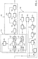
- the structure shown in FIG. 1 firstly comprises a format conversion circuit 10 which receives the digital input signals, in the present case from the television images, with two interlaced fields. These input signals here correspond to luminance or chrominance signals.
- the blocks of pixels thus formed are then sent to two channels 11 and 21 in parallel, intended for filtering the blocks thus obtained.
- the first filtering channel 11 comprises weighted vertical filtering means which, in the example described, themselves include, in series, a first vertical filter 12, a first circuit 13 for absolute value extraction, and a first circuit 14 of accumulation, over the entire block considered, of the output signals of the previous circuit.
- the second filtering path 21 comprises similar means, namely, in series, a second vertical filter 22, a second circuit 23 for extraction of absolute value, and a second accumulation circuit 24.
- the circuits of absolute value extraction are particularly useful in image areas where the pixels considered for the vertical filtering are in the vicinity of borders between regions of different luminance or chrominance levels.
- the first vertical filter 12 is an intra-image filter, operating between N successive lines of the image block considered, with N odd.
- the sum of the filter coefficients attached respectively to each line is preferably zero, and these coefficients are symmetrical with respect to the central line of these N lines.
- the vertical filter chosen operates between three successive lines M-1, M, M + 1, with coefficients here equal to 1, -2, 1 respectively for each of the three pixels considered (1 for the pixels of lines M-1 and M + 1, which belong to one of the two frames, -2 for the pixel of the line M, which belongs to the other frame).
- the second vertical filter 22 is itself an intra-frame filter, operating between N successive lines of the same frame in the image block considered.
- the number N is identical to that chosen in the case of the first filter, and the central line is the same in both cases.
- the filter coefficients are the same as above, and are therefore symmetrical with respect to this central line, with a sum also zero.
- the vertical filter therefore operates here between three lines M-2, M, M + 2, with coefficients also equal to 1, -2, 1 respectively for each pixels considered.
- each accumulation circuit, 14 or 24 After extraction of absolute value (by circuits 13 and 23), each accumulation circuit, 14 or 24 respectively, performs the sum of all the signals resulting from the corresponding vertical filtering, operated for each of the pixels of the image block considered. If the central pixel of the filter is on the first or on the last line, use is made exceptionally of pixels neighboring another image block.
- the respective outputs of circuits 14 and 24 are then sent to the first and second inputs of a comparator 30 which performs the comparison of the signals of output of the first and second filtering channels, that is to say the comparison of the accumulated filtered signals.
- the existence of an inter-frame movement or not is noted depending on whether the output of the first filter channel 11 is greater or on the contrary less than that of the second filter channel 21.
- the output signal of the comparator 30 plays the role of the switching signal mentioned in the description of the system according to the cited European patent application.
- the movement detection stage comprises, similarly to what has been seen previously with reference to FIG. 1, a format 50 conversion circuit, identical to circuit 10 , and two filtering channels 51 and 61 in parallel, which, as before, include the weighted vertical filtering means provided in the context of the invention.
- the first filtering channel 51 comprises, in series, a first circuit 52 for calculating, for each of the upper and lower half-columns of each column of the block considered, the average of the signals associated with each point image, a first circuit 53 for calculating variance for each of said upper and lower half-columns, and a first circuit 54 for adding the variances thus calculated for all of said upper and lower half-columns (that is i.e. for all columns).
- This filtering channel 51 is provided for operating on each of the successive lines of the entire block (therefore on lines which successively belong to one of the frames and to the other).
- the second filtering channel 61 comprises, in series, similar means, namely second circuits 62 to 64, but it is this time intended to operate, throughout the block with interlaced frames, successively on each of the successive lines of one of the two frames, then, distinctly, on each of the successive lines of the other frame.
- the sum of the variances is, in this case, lower than the sum calculated by the circuit 54 for the same block.
- a comparator 70 which receives the respective outputs of circuits 54 and 64 on its first and second inputs, delivers an output signal which expresses this situation of existence or absence of an inter-frame movement and which, like that of comparator 30, plays the role of the switching signal mentioned in the description of the system according to the cited document.
- a motion detection stage as described in the previous embodiments can be used for example in a coding device like that shown in FIG. 4.
- This device comprises, in this example, on the one hand, in a conventional manner, a coding channel 101 and an associated prediction channel 102, and on the other hand a sub-assembly 103 for deinterleaving the blocks in the event of inter-frame movement, including a movement detection stage according to the invention.
- the coding channel 101 comprises, in series, a discrete cosine transformation circuit 110, a quantization circuit 120, a variable length coding circuit 130, and a buffer memory 140 for storing the coded words, as well as , between this memory and the quantization circuit, a flow regulation circuit 150.
- the prediction channel 102 provided at the output of the quantization circuit 120, comprises in series a reverse quantization circuit 160, a reverse discrete cosine transformation circuit 170, and a prediction subset 175 to 195.
- the output signals of the circuit 170 are sent, via a switching stage present in said sub-assembly 103 and described below, to a first input of an adder 185 whose output is stored in an image memory 175.
- the output of this memory 175 is sent to a motion compensation stage which includes a motion estimation circuit 180 and a motion compensation circuit 190 (it is this circuit 190 which, on a first input, receives the output of said memory 175).
- the circuit 180 here receives the digital input signals from the coding device and determines here, for each image block, a displacement vector representative of its movement relative to the corresponding block of the previous image (this determination is known as the name of block to block recognition, or "block matching" in English).
- the vector thus determined is sent to the second input of the motion compensation circuit 190, and the latter delivers a predicted block whose difference with the previous block is determined in a subtractor 200 placed upstream of the discrete cosine transformation circuit 110.
- the predicted block is also returned to a second input of the adder 185.
- the subtractor 200 receives on a first input the output of a format conversion circuit 195 which, itself, receives the digital input signals from the device (corresponding to images) to present them, at its output, in blocks . These digital output signals from the subtractor 200, corresponding to the successive image blocks and representing the difference between each current image block and the predicted block which is deduced therefrom after the operations carried out in the prediction channel, are then sent, by through the deinterlacing subset described below, to the input of the discrete cosine transformation circuit 110.
- the sub-assembly 103 for deinterleaving the blocks comprises, in accordance with the invention, on the one hand a movement detection stage 210, as described in one of the preceding embodiments, and on the other hand a stage of switching according to the result of said detection, itself comprising on the one hand, in the coding channel 101, a first switch 221 whose common input is connected to the output of the subtractor 200, a second switch 222 whose common output is connected to the input of the discrete cosine transformation circuit 110, and, between the non-common terminals of these two switches 221 and 222, two branches in parallel, one of which is a direct link 223 between said output of subtractor 200 and said input of circuit 110 and the other of which performs the same connection but via a block deinterlacing circuit 224, and on the other hand, in prediction channel 102, a third switch 231 whose input common is connected to the output of circuit 170 of discrete inverse cosine transformation, a fourth switch 232 whose common output is connected
- the predicted block must however be available in interlaced form (since the difference calculation performed by the subtractor 200 is located before said deinterlacing operation), so that the difference between current and predicted blocks is determined from blocks of the same structure.
- the motion detection stage which has been described above in various embodiments finds its place particularly in a set of coding of digital signals corresponding to television images, such as that which is the subject of said document, or in a coding device such as that which has just been described.
- these applications are not limiting, as are the dimensions of the blocks considered.
Abstract
Description
La présente invention concerne un étage de détection de mouvement dans des signaux numériques correspondant à des images initiales à trames entrelacées, ainsi qu'un dispositif de codage de ces signaux incluant un tel étage de détection de mouvement. Cette invention est applicable notamment dans le domaine du codage d'images de télévision, pour la transmission et/ou l'enregistrement de signaux de télévision numériques (luminance ou chrominance), ou bien dans le domaine de la conversion de format.The present invention relates to a motion detection stage in digital signals corresponding to initial images with interlaced frames, as well as a device for coding these signals including such a motion detection stage. This invention is applicable in particular in the field of coding of television images, for the transmission and / or recording of digital television signals (luminance or chrominance), or else in the field of format conversion.
La demande de brevet européen EP-0282135 décrit un système de télévision comprenant une partie codage et une partie décodage. Dans la partie codage du système, qui est par exemple un enregistreur vidéo, des signaux analogiques d'origine sont échantillonnés puis convertis en signaux numériques. Ces signaux numériques, qui sont représentatifs des images d'origine, sont subdivisés en blocs de signaux correspondant à M x N points d'image (ou pixels), avec par exemple M = N = 8 ou 16 dans de nombreux cas. Les blocs ainsi constitués subissent une transformation (ici une transformation cosinus discrète) en un jeu de coefficients y(i,k) qui sont alors fournis à un circuit de codage à longueur variable (i et k désignent les numéros des lignes et des colonnes desdits coefficients dans le tableau qu'ils constituent).European patent application EP-0282135 describes a television system comprising an encoding part and a decoding part. In the coding part of the system, which is for example a video recorder, original analog signals are sampled and then converted into digital signals. These digital signals, which are representative of the original images, are subdivided into blocks of signals corresponding to M x N image points (or pixels), with for example M = N = 8 or 16 in many cases. The blocks thus formed undergo a transformation (here a discrete cosine transformation) into a set of coefficients y (i, k) which are then supplied to a variable length coding circuit (i and k denote the numbers of the rows and columns of said blocks. coefficients in the table they constitute).
Cette partie codage du système comprend également un détecteur de mouvement qui émet un signal de commutation entre deux modes de fonctionnement, à savoir un mode dit intra-trame et un mode dit intra-image. En effet, les prises de vue des deux trames d'une image sont réalisées à des moments différents, et, localement, deux lignes d'image adjacentes (et appartenant donc l'une à une trame et l'autre à l'autre trame) peuvent avoir des niveaux de luminance et/ou de chrominance très différents, qui se traduisent visuellement, au niveau des images finalement reconstituées après décodage, par des effets de scintillement de ligne. Le détecteur de mouvement a pour objet de déterminer si un objet présent dans une image s'est déplacé ou non pendant l'intervalle de temps qui sépare deux trames successives, et si, en outre, ce mouvement, lorsqu'il existe, est perceptible dans un bloc d'image (qui ne représente, on l'a vu, qu'une faible fraction de l'image, 64 pixels dans le cas d'un bloc de 8 x 8 pixels).This coding part of the system also includes a motion detector which transmits a switching signal between two operating modes, namely a so-called intra-frame mode and a so-called intra-picture mode. Indeed, the shots of the two frames of an image are taken at different times, and, locally, two adjacent image lines (and therefore belonging one to a frame and the other to the other frame ) can have very different levels of luminance and / or chrominance, which translate visually, at the level of the images finally reconstructed after decoding, by effects flickering line. The object of the motion detector is to determine whether or not an object present in an image has moved during the time interval which separates two successive frames, and if, moreover, this movement, when it exists, is perceptible. in an image block (which, as we have seen, represents only a small fraction of the image, 64 pixels in the case of an 8 x 8 pixel block).
Pour l'une des deux valeurs possibles du signal de commutation délivré par le détecteur de mouvement, ce dernier place le système en mode intra-image (pas de mouvement notable), et, pour l'autre valeur, en mode intra-trame (existence d'un mouvement perceptible au niveau du bloc d'image). La sélection d'un mode ou de l'autre affecte les signaux d'origine au niveau de la transformation qu'ils subissent : en mode intra-image, les blocs sont traités tels quels, alors qu'en mode intra-trame, les deux trames de chaque bloc sont préalablement séparées en deux sous-blocs comprenant l'un les lignes impaires du bloc et l'autre les lignes paires. Les valeurs des coefficients obtenus alors par ladite transformation sur chacun desdits sous-blocs ne sont maintenant plus perturbées par l'existence de mouvement dans l'image, qui se traduit visuellement par les effets de scintillement de ligne mentionnés plus haut, et une réduction sensible du débit après codage est obtenue par rapport au cas où le mode intra-image serait maintenu malgré l'existence du mouvement inter-trames.For one of the two possible values of the switching signal delivered by the motion detector, the latter places the system in intra-image mode (no significant movement), and, for the other value, in intra-frame mode ( existence of a perceptible movement at the level of the image block). The selection of one mode or the other affects the original signals at the level of the transformation they undergo: in intra-image mode, the blocks are treated as they are, while in intra-frame mode, the two frames of each block are previously separated into two sub-blocks comprising one the odd lines of the block and the other the even lines. The values of the coefficients then obtained by said transformation on each of said sub-blocks are no longer disturbed by the existence of movement in the image, which is visually reflected by the line flicker effects mentioned above, and a significant reduction. the bit rate after coding is obtained compared to the case where the intra-image mode would be maintained despite the existence of the inter-frame movement.
Dans le document cité et dont le contenu vient d'être succinctement rappelé, le principe de fonctionnement du détecteur de mouvement repose sur une mesure de fréquence dans la direction verticale. Plus précisément, chaque bloc d'image (de dimension 8 x 8 pixels) subit une transformation dite de Hadamard, à la suite de laquelle la présence de la plus grande fréquence verticale dans le bloc est connue par l'intermédiaire de la valeur du coefficient y(1,8), dont l'expression est donnée par la relation suivante :

où x(i,k) est représentatif de la valeur du niveau de gris attachée, dans le bloc considéré, au pixel de la ligne i et de la colonne k. Cette valeur de coefficient est comparée à un seuil, et le résultat de cette comparaison commande l'émission dudit signal de commutation et donc le choix du mode intra-image ou du mode intra-trame.In the document cited and the content of which has just been briefly recalled, the operating principle of the motion detector is based on a frequency measurement in the vertical direction. More precisely, each image block (of dimension 8 × 8 pixels) undergoes a so-called Hadamard transformation, as a result of which the presence of the greatest vertical frequency in the block is known by means of the value of the coefficient y (1,8), the expression of which is given by the following relation:
where x (i, k) is representative of the value of the gray level attached, in the block considered, to the pixel of line i and of column k. This coefficient value is compared with a threshold, and the result of this comparison controls the emission of said switching signal and therefore the choice of the intra-image mode or the intra-frame mode.
Cependant, la mise en oeuvre de ce principe de fonctionnement ne peut pas être considérée comme satisfaisante. Certains blocs d'image, caractérisés par l'existence d'un mouvement inter-trames déterminé, ne sont pourtant pas détectés comme tels et restent traités selon le mode intra-image, ce qui, quelle que soit l'application considérée, conduit à un fonctionnement non optimal.However, the implementation of this operating principle cannot be considered satisfactory. Certain image blocks, characterized by the existence of a determined inter-frame movement, are however not detected as such and remain processed according to the intra-image mode, which, whatever the application considered, leads to non-optimal operation.
Un premier but de l'invention est de proposer un étage de détection de mouvement dont le fonctionnement s'avère plus sûr que dans le cas précédemment décrit.A first object of the invention is to propose a movement detection stage, the operation of which proves to be safer than in the case described above.
A cet effet l'invention concerne un étage de détection de mouvement tel que défini dans le préambule de la description et qui est en outre caractérisé en ce qu'il comprend :
- (a) un circuit de conversion de format, pour la subdivision desdits signaux en blocs de m x n points d'image, ou en macroblocs de (p x m) x (q x n) points d'image regroupant un nombre déterminé desdits blocs, les nombres m, n, p et q étant des entiers positifs ;
- (b) en parallèle sur la sortie dudit circuit, des première et deuxième voies de filtrage de chacun desdits blocs ou macroblocs, comprenant chacune des moyens de filtrage vertical pondéré prévus pour opérer sur des lignes d'image successives de chaque bloc ou macrobloc dans le cas de la première voie de filtrage et sur des lignes de trame successives de chaque bloc ou macrobloc dans le cas de la deuxième voie de filtrage ;
- (c) un comparateur des signaux de sortie desdites première et deuxième voies de filtrage.
- (a) a format conversion circuit, for the subdivision of said signals into blocks of mxn picture points, or into macroblocks of (pxm) x (qxn) picture points grouping together a determined number of said blocks, the numbers m, n, p and q being positive integers;
- (b) in parallel on the output of said circuit, first and second filtering channels of each of said blocks or macroblocks, each comprising weighted vertical filtering means provided for operating on successive image lines of each block or macroblock in the case of the first filtering channel and on successive frame lines of each block or macroblock in the case of the second filtering channel;
- (c) a comparator of the output signals of said first and second filtering channels.
La structure ainsi proposée est avantageuse en ce sens qu'elle repose sur un principe de fonctionnement qui consiste à comparer d'une part des données de bloc attachées à une trame seulement et d'autre part des données de bloc correspondant aux deux trames, c'est-à-dire à comparer réellement des signaux en présence éventuelle de mouvement et en l'absence de mouvement, avant de faire le choix du mode de transformation optimal en fonction de l'application considérée (c'est-à-dire le choix qui conduira à la réduction de débit la plus efficace dans le cas d'une application au codage de signaux, ou bien, dans le cas d'une application à la conversion de format, le choix qui conduira à la façon la plus appropriée de réaliser cette conversion). L'application d'un tel critère s'avère en effet bien plus concluante que dans la réalisation antérieure précédemment décrite, dans la mesure où, après détection de l'existence du mouvement, le choix du mode de fonctionnement compte tenu de l'application est plus pertinent.The structure thus proposed is advantageous in that it is based on an operating principle which consists in comparing on the one hand block data attached to only one frame and on the other hand block data corresponding to the two frames, that is to say to actually compare signals in the event of possible movement and in the absence of movement, before choosing the mode of optimal transformation according to the application considered (i.e. the choice which will lead to the most effective rate reduction in the case of an application for signal coding, or else, in the case of a application to format conversion, the choice which will lead to the most appropriate way to carry out this conversion). The application of such a criterion turns out to be much more conclusive than in the previous embodiment described above, insofar as, after detection of the existence of the movement, the choice of the operating mode taking into account the application is more relevant.
Dans un premier mode de réalisation de l'invention, cet étage de détection de mouvement est caractérisé en ce que, dans chacune des voies de filtrage, lesdits moyens de filtrage vertical pondéré comprennent un circuit de filtrage vertical, un circuit d'extraction de valeur absolue et un circuit d'accumulation, chaque circuit de filtrage vertical étant prévu pour opérer sur N lignes, avec N impair et symétrie des coefficients de filtrage par rapport à la ligne centrale commune, lesdites lignes étant N lignes d'image successives de chaque bloc ou macrobloc dans le cas de la première voie de filtrage et, dans le cas de la deuxième voie de filtrage, N lignes successives de celle des deux trames à laquelle, dans ledit bloc ou macrobloc, appartient ladite ligne centrale, de rang (N+1)/2, desdites N lignes d'image successives. La somme des coefficients de filtrage pour chaque circuit de filtrage est de préférence nulle.In a first embodiment of the invention, this movement detection stage is characterized in that, in each of the filtering channels, said weighted vertical filtering means comprise a vertical filtering circuit, a value extraction circuit absolute and an accumulation circuit, each vertical filtering circuit being provided to operate on N lines, with N odd and symmetry of the filter coefficients with respect to the common central line, said lines being N successive image lines of each block or macroblock in the case of the first filtering channel and, in the case of the second filtering channel, N successive lines of that of the two frames to which, in said block or macroblock, belongs said central line, of rank (N + 1) / 2, of said N successive image lines. The sum of the filter coefficients for each filter circuit is preferably zero.
Dans une structure particulièrement simple de ce premier mode de réalisation, l'étage de détection de mouvement est caractérisé en ce que le premier circuit de filtrage vertical est prévu pour opérer entre trois lignes successives de rang M-1, M, M+1 de chaque bloc ou macrobloc et en ce que le deuxième circuit de filtrage vertical est prévu pour opérer entre trois lignes successives de rang M-2, M, M+2 de la même trame dans chaque bloc ou macrobloc, avec, pour chaque filtre, des coefficients respectivement égaux à 1, -2, 1 pour chacun des trois points d'image ainsi considérés.In a particularly simple structure of this first embodiment, the movement detection stage is characterized in that the first vertical filtering circuit is provided for operating between three successive lines of rank M-1, M, M + 1 of each block or macroblock and in that the second vertical filtering circuit is provided for operating between three successive rows of rank M-2, M, M + 2 of the same frame in each block or macroblock, with, for each filter, coefficients respectively equal to 1, -2, 1 for each of the three image points thus considered.
Dans un deuxième mode de réalisation de l'invention, l'étage de détection de mouvement est caractérisé en ce que, dans chacune des voies de filtrage, lesdits moyens de filtrage vertical pondéré comprennent un circuit de calcul, pour chacune des demi-colonnes supérieure et inférieure de chaque colonne du bloc ou du macrobloc considéré, de la moyenne desdits signaux associés à chaque point d'image, un circuit de calcul de variance pour chacune desdites demi-colonnes supérieure et inférieure, et un circuit d'addition des variances ainsi calculées pour l'ensemble desdites demi-colonnes supérieures et inférieures, la première voie de filtrage étant prévue pour opérer sur chaque ligne successive de tout le bloc ou macrobloc à trames entrelacées et la deuxième voie de filtrage étant prévue pour opérer, dans tout le bloc ou macrobloc à trames entrelacées, successivement et distinctement sur chaque ligne successive d'une des trames et sur chaque ligne successive de l'autre trame.In a second embodiment of the invention, the motion detection stage is characterized in that, in each of the filtering channels, said weighted vertical filtering means comprise a calculation circuit, for each of the upper half-columns and lower of each column of the block or of the macroblock considered, of the average of said signals associated with each image point, a circuit for calculating variance for each of said upper and lower half-columns, and a circuit for adding variances thus calculated for all of said upper and lower half-columns, the first filtering channel being provided to operate on each successive line of the entire block or macroblock with interlaced frames and the second filtering channel being provided to operate, throughout the block or macroblock with interlaced frames, successively and distinctly on each successive line of one of the frames and on each successive line d e the other frame.
Un autre but de l'invention est également de proposer l'utilisation d'un étage de détection de mouvement tel que défini précédemment dans un dispositif de codage de signaux numériques correspondant à des images initiales à trames entrelacées subdivisés en blocs ou en macroblocs regroupant un nombre déterminé desdits blocs, comprenant une voie de codage à longueur variable et une voie de prédiction associée.Another object of the invention is also to propose the use of a motion detection stage as defined above in a device for coding digital signals corresponding to initial images with interlaced frames subdivided into blocks or macroblocks grouping together a determined number of said blocks, comprising a variable length coding channel and an associated prediction channel.
L'invention concerne à cet effet un dispositif de codage, caractérisé en ce qu'il comprend également un sous-ensemble de désentrelacement des blocs, ou des macroblocs, comprenant lui-même :
- (a) un étage de détection de mouvement selon l'une des structures définies précédemment, prévu pour recevoir les signaux destinés à ladite voie de codage ;
- (b) un étage de commutation prévu pour autoriser dans la voie de codage, en réponse audit étage de détection, le désentrelacement des blocs ou macroblocs et, de façon correspondante dans la voie de prédiction associée, le réentrelacement des blocs ou macroblocs.
- (a) a motion detection stage according to one of the structures defined above, designed to receive the signals intended for said coding channel;
- (b) a switching stage provided for authorizing in the coding channel, in response to said detection stage, the deinterlacing of the blocks or macroblocks and, so corresponding in the associated prediction channel, the reinterlacing of blocks or macroblocks.
Dans un mode préférentiel de réalisation, ce dispositif de codage, dans lequel la voie de codage comprend, en série, un circuit de transformation cosinus discrète, un circuit de quantification, un circuit de codage à longueur variable, et une mémoire-tampon de stockage des mots codés, ainsi que, entre cette mémoire et le circuit de quantification, un circuit de régulation de débit, et la voie de prédiction associée, comprend en série, en sortie du circuit de quantification, un circuit de quantification inverse, un circuit de transformation cosinus discrète inverse, un sous-ensemble de prédiction avec compensation de mouvement, et un soustracteur délivrant des signaux de différence entre chaque bloc d'image courant et chaque bloc prédit, est plus particulièrement caractérisé en ce que l'étage de commutation comprend lui-même :
- (a) dans la voie de codage, un premier commutateur dont l'entrée commune est reliée à la sortie du soustracteur, un deuxième commutateur dont la sortie commune est reliée à l'entrée du circuit de transformation cosinus discrète, et, entre les bornes non communes de ces deux commutateurs, deux branches en parallèle dont l'une est une liaison directe et dont l'autre réalise la même liaison mais par l'intermédiaire d'un circuit de désentrelacement de bloc ;
- (b) dans la voie de prédiction, un troisième commutateur dont l'entrée commune est reliée à la sortie du circuit de transformation cosinus discrète inverse, un quatrième commutateur dont la sortie commune est reliée au sous-ensemble de prédiction, et, entre les bornes non communes de ces deux commutateurs, deux autres branches en parallèle dont l'une est une liaison directe et dont l'autre réalise la même liaison mais par l'intermédiaire d'un circuit de réentrelacement de bloc.
- (a) in the coding channel, a first switch whose common input is connected to the output of the subtractor, a second switch whose common output is connected to the input of the discrete cosine transformation circuit, and, between the terminals these two switches are not common, two branches in parallel, one of which is a direct link and the other of which makes the same link but via a block deinterlacing circuit;
- (b) in the prediction channel, a third switch whose common input is connected to the output of the inverse discrete cosine transformation circuit, a fourth switch whose common output is connected to the prediction sub-assembly, and, between the non-common terminals of these two switches, two other branches in parallel, one of which is a direct link and the other of which makes the same link but via a block re-interleaving circuit.
Les particularités de l'invention apparaîtront maintenant de façon plus précise dans la description qui suit et dans les dessins annexés, donnés à titre d'exemple non limitatif et dans lesquels :
- la figure 1 montre un premier exemple de réalisation de l'étage de détection de mouvement selon l'invention :
- la figure 2 illustre le choix des lignes de chaque bloc d'image sur lesquelles sont réalisés les filtrages verticaux prévus dans ledit étage de détection de mouvement de la figure 1 ;
- la figure 3 montre un deuxième exemple de réalisation de l'étage de détection de mouvement selon l'invention ;
- la figure 4 montre un exemple de réalisation d'un dispositif de codage comprenant un étage de détection de mouvement conforme à l'invention.
- FIG. 1 shows a first embodiment of the motion detection stage according to the invention:
- FIG. 2 illustrates the choice of the lines of each image block on which the vertical filterings provided for in said motion detection stage of FIG. 1 are carried out;
- Figure 3 shows a second embodiment of the motion detection stage according to the invention;
- FIG. 4 shows an exemplary embodiment of a coding device comprising a movement detection stage according to the invention.
La structure représentée sur la figure 1 comprend tout d'abord un circuit de conversion de format 10 qui reçoit les signaux numériques d'entrée, dans le cas présent des images de télévision, à deux trames entrelacées. Ces signaux d'entrée correspondent ici à des signaux de luminance ou de chrominance. Le circuit 10 assure la subdivision des signaux d'origine, correspondant aux images, en blocs de m x n pixels, qui sont toujours à trames entrelacées, comme lesdites images d'origine (dans de nombreuses applications, on prend par exemple m = n = 8, ou 16).The structure shown in FIG. 1 firstly comprises a
Les blocs de pixels ainsi constitués sont alors envoyés vers deux voies 11 et 21 en parallèle, destinées au filtrage des blocs ainsi obtenus. La première voie de filtrage 11 comprend des moyens de filtrage vertical pondéré qui, dans l'exemple décrit, comprennent eux-mêmes, en série, un premier filtre vertical 12, un premier circuit 13 d'extraction de valeur absolue, et un premier circuit 14 d'accumulation, sur tout le bloc considéré, des signaux de sortie du circuit précédent. De même, la deuxième voie de filtrage 21 comprend des moyens similaires, à savoir, en série, un deuxième filtre vertical 22, un deuxième circuit 23 d'extraction de valeur absolue, et un deuxième circuit d'accumulation 24. Les circuits d'extraction de valeur absolue sont particulièrement utiles dans les zones d'image où les pixels considérés pour le filtrage vertical sont au voisinage de frontières entre des régions de niveaux de luminance ou de chrominance différents.The blocks of pixels thus formed are then sent to two
Le premier filtre vertical 12 est un filtre intra-image, opérant entre N lignes successives du bloc d'image considéré, avec N impair. La somme des coefficients de filtrage attachés respectivement à chaque ligne est de préférence nulle, et ces coefficients sont symétriques par rapport à la ligne centrale de ces N lignes. Dans l'exemple ici décrit, illustré sur la partie gauche de la figure 2 représentant les huit lignes d'un bloc de 8 x 8 pixels, le filtre vertical choisi opère entre trois lignes successives M-1, M, M+1, avec des coefficients ici égaux à 1, -2, 1 respectivement pour chacun des trois pixels considérés (1 pour les pixels des lignes M-1 et M+1, qui appartiennent à l'une des deux trames, -2 pour le pixel de la ligne M, qui appartient à l'autre trame).The first
Le deuxième filtre vertical 22 est, lui, un filtre intra-trame, opérant entre N lignes successives de la même trame dans le bloc d'image considéré. Dans ce deuxième filtre, le nombre N est identique à celui choisi dans le cas du premier filtre, et la ligne centrale est la même dans les deux cas. Les coefficients de filtrage sont les mêmes que précédemment, et sont donc symétriques par rapport à cette ligne centrale, avec une somme également nulle. Dans l'exemple décrit, illustré sur la partie droite de la figure 2, le filtre vertical opère donc ici entre trois lignes M-2, M, M+2, avec des coefficients égaux aussi à 1, -2, 1 respectivement pour chacun des pixels considérés.The second
Après extraction de valeur absolue (par les circuits 13 et 23), chaque circuit d'accumulation, 14 ou 24 respectivement, effectue la somme de tous les signaux résultant du filtrage vertical correspondant, opéré pour chacun des pixels du bloc d'image considéré. Si le pixel central du filtre est sur la première ou sur la dernière ligne, on fait à ce moment-là exceptionnellement appel à des pixels voisins d'un autre bloc d'image. Les sorties respectives des circuits 14 et 24 sont alors envoyées vers les première et deuxième entrées d'un comparateur 30 qui effectue la comparaison des signaux de sortie des première et deuxième voies de filtrage, c'est-à-dire la comparaison des signaux filtrés accumulés. L'existence d'un mouvement inter-trames ou non est constatée selon que la sortie de la première voie de filtrage 11 est supérieure ou au contraire inférieure à celle de la deuxième voie de filtrage 21. Le signal de sortie du comparateur 30 joue le rôle du signal de commutation mentionné dans la description du système selon la demande de brevet européen citée.After extraction of absolute value (by
Dans un deuxième mode de réalisation représenté sur la figure 3, l'étage de détection de mouvement comprend, de façon similaire à ce qui a été vu précédemment en référence à la figure 1, un circuit de conversion de format 50, identique au circuit 10, et deux voies de filtrage 51 et 61 en parallèle, qui, comme précédemment, incluent les moyens de filtrage vertical pondéré prévus dans le cadre de l'invention. Dans l'exemple ici décrit, la première voie de filtrage 51 comprend, en série, un premier circuit 52 de calcul, pour chacune des demi-colonnes supérieure et inférieure de chaque colonne du bloc considéré, de la moyenne des signaux associés à chaque point d'image, un premier circuit 53 de calcul de variance pour chacune desdites demi-colonnes supérieure et inférieure, et un premier circuit 54 d'addition des variances ainsi calculées pour l'ensemble desdites demi-colonnes supérieures et inférieures (c'est-à-dire pour l'ensemble des colonnes). Cette voie de filtrage 51 est prévue pour opérer sur chacune des lignes successives de tout le bloc (donc sur des lignes qui appartiennent successivement à l'une des trames et à l'autre).In a second embodiment represented in FIG. 3, the movement detection stage comprises, similarly to what has been seen previously with reference to FIG. 1, a
De même, la deuxième voie de filtrage 61 comprend, en série, des moyens similaires, à savoir des deuxièmes circuits 62 à 64, mais elle est cette fois prévue pour opérer, dans tout le bloc à trames entrelacées, successivement sur chacune des lignes successives de l'une des deux trames, puis, distinctement, sur chacune des lignes successives de l'autre trame. En cas de mouvement dans une image, la somme des variances est, dans ce cas, plus faible que la somme calculée par le circuit 54 pour le même bloc. Un comparateur 70, qui reçoit les sorties respectives des circuits 54 et 64 sur ses première et deuxième entrées, délivre un signal de sortie qui exprime cette situation d'existence ou d'absence d'un mouvement inter-trames et qui, comme celui du comparateur 30, joue le rôle du signal de commutation mentionné dans la description du système selon le document cité.Likewise, the
Un étage de détection de mouvement tel que décrit dans les modes de réalisation précédents peut être utilisé par exemple dans un dispositif de codage comme celui représenté sur la figure 4. Ce dispositif comprend, dans cet exemple, d'une part, de façon classique, une voie de codage 101 et une voie de prédiction associée 102, et d'autre part un sous-ensemble 103 de désentrelacement des blocs en cas de mouvement inter-trames, incluant un étage de détection de mouvement selon l'invention.A motion detection stage as described in the previous embodiments can be used for example in a coding device like that shown in FIG. 4. This device comprises, in this example, on the one hand, in a conventional manner, a
Plus précisément, la voie de codage 101 comprend, en série, un circuit 110 de transformation cosinus discrète, un circuit de quantification 120, un circuit 130 de codage à longueur variable, et une mémoire-tampon 140 de stockage des mots codés, ainsi que, entre cette mémoire et le circuit de quantification, un circuit 150 de régulation de débit. La voie de prédiction 102, prévue en sortie du circuit de quantification 120, comprend en série un circuit de quantification inverse 160, un circuit 170 de transformation cosinus discrète inverse, et un sous-ensemble de prédiction 175 à 195. Les signaux de sortie du circuit 170 sont envoyés, par l'intermédiaire d'un étage de commutation présent dans ledit sous-ensemble 103 et décrit plus loin, vers une première entrée d'un additionneur 185 dont la sortie est stockée dans une mémoire d'image 175. La sortie de cette mémoire 175 est envoyée vers un étage de compensation de mouvement qui comprend un circuit d'estimation de mouvement 180 et un circuit de compensation de mouvement 190 (c'est ce circuit 190 qui, sur une première entrée, reçoit la sortie de ladite mémoire 175). Le circuit 180 reçoit ici les signaux numériques d'entrée du dispositif de codage et détermine ici, pour chaque bloc d'image, un vecteur de déplacement représentatif de son mouvement par rapport au bloc correspondant de l'image précédente (cette détermination est connue sous le nom de reconnaissance bloc à bloc, ou "block matching" en anglais). Le vecteur ainsi déterminé est envoyé vers la deuxième entrée du circuit de compensation de mouvement 190, et celui-ci délivre un bloc prédit dont la différence avec le bloc précédent est déterminée dans un soustracteur 200 placé en amont du circuit de transformation cosinus discrète 110. Le bloc prédit est également renvoyé vers une deuxième entrée de l'additionneur 185.More specifically, the
Le soustracteur 200 reçoit sur une première entrée la sortie d'un circuit 195 de conversion de format qui, lui-même, reçoit les signaux numériques d'entrée du dispositif (correspondant à des images) pour les présenter, à sa sortie, par blocs. Ces signaux numériques de sortie du soustracteur 200, correspondant aux blocs d'image successifs et représentant la différence entre chaque bloc d'image courant et le bloc prédit qui en est déduit après les opérations effectuées dans la voie de prédiction, sont alors envoyés, par l'intermédiaire du sous-ensemble de désentrelacement décrit ci-après, vers l'entrée du circuit 110 de transformation cosinus discrète.The
Le sous-ensemble 103 de désentrelacement des blocs comprend, conformément à l'invention, d'une part un étage de détection de mouvement 210, tel que décrit dans l'un des modes de réalisation précédents, et d'autre part un étage de commutation selon le résultat de ladite détection, comprenant lui-même d'une part, dans la voie de codage 101, un premier commutateur 221 dont l'entrée commune est reliée à la sortie du soustracteur 200, un deuxième commutateur 222 dont la sortie commune est reliée à l'entrée du circuit 110 de transformation cosinus discrète, et, entre les bornes non communes de ces deux commutateurs 221 et 222, deux branches en parallèle dont l'une est une liaison directe 223 entre ladite sortie du soustracteur 200 et ladite entrée du circuit 110 et dont l'autre réalise la même liaison mais par l'intermédiaire d'un circuit 224 de désentrelacement de bloc, et d'autre part, dans la voie de prédiction 102, un troisième commutateur 231 dont l'entrée commune est reliée à la sortie du circuit 170 de transformation cosinus discrète inverse, un quatrième commutateur 232 dont la sortie commune est reliée à la première entrée de l'additionneur 185, et, entre les bornes non communes de ces deux commutateurs 231 et 232, deux autres branches en parallèle dont l'une est une liaison directe 233 entre ladite sortie du circuit 170 et ladite première entrée de l'additionneur 185 et dont l'autre réalise la même liaison mais par l'intermédiaire d'un circuit 234 de réentrelacement de bloc. En effet, si, par suite de la détection d'un mouvement suffisant, le bloc courant a été désentrelacé avant transformation cosinus discrète, le bloc prédit doit être cependant disponible sous forme entrelacée (puisque le calcul de différence réalisé par le soustracteur 200 se situe avant ladite opération de désentrelacement), afin que la différence entre blocs courant et prédit soit déterminée à partir de blocs de même structure.The sub-assembly 103 for deinterleaving the blocks comprises, in accordance with the invention, on the one hand a movement detection stage 210, as described in one of the preceding embodiments, and on the other hand a stage of switching according to the result of said detection, itself comprising on the one hand, in the coding channel 101, a first switch 221 whose common input is connected to the output of the subtractor 200, a second switch 222 whose common output is connected to the input of the discrete cosine transformation circuit 110, and, between the non-common terminals of these two switches 221 and 222, two branches in parallel, one of which is a direct link 223 between said output of subtractor 200 and said input of circuit 110 and the other of which performs the same connection but via a block deinterlacing circuit 224, and on the other hand, in prediction channel 102, a third switch 231 whose input common is connected to the output of circuit 170 of discrete inverse cosine transformation, a fourth switch 232 whose common output is connected to the first input of adder 185, and, between the non-common terminals of these two switches 231 and 232, two other branches in parallel, one of which is a direct link 233 between said output of circuit 170 and said first input of adder 185 and the other of which makes the same connection but via a circuit 234 for block re-interleaving. Indeed, if, following the detection of sufficient movement, the current block has been deinterleaved before discrete cosine transformation, the predicted block must however be available in interlaced form (since the difference calculation performed by the
Bien entendu, la présente invention n'est pas limitée aux exemples de réalisation ci-dessus et représentés, à partir desquels des variantes peuvent être proposées sans pour cela sortir du cadre de l'invention. Il est manifeste, en particulier, que les signaux correspondant aux images, traités par blocs dans les exemples décrits jusqu'à présent, peuvent être regroupés différemment et par exemple traités par macroblocs de (p x m) x (q x n) points d'image, ces macroblocs regroupant un nombre déterminé de blocs, avec p et q entiers (un exemple couramment choisi est p = q = 2).Of course, the present invention is not limited to the embodiments above and shown, from which variants can be proposed without thereby departing from the scope of the invention. It is evident, in particular, that the signals corresponding to the images, processed by blocks in the examples described so far, can be grouped differently and for example processed by macroblocks of (pxm) x (qxn) image points, these macroblocks grouping together a determined number of blocks, with p and q integers (a commonly chosen example is p = q = 2).
Par ailleurs, l'étage de détection de mouvement qui a été décrit plus haut dans diverses réalisations trouve tout particulièrement sa place dans un ensemble de codage de signaux numériques correspondant à des images de télévision, tel que celui qui fait l'objet dudit document, ou dans un dispositif de codage tel que celui qui vient d'être décrit. Cependant, comme on l'a vu, ces applications, ne sont pas limitatives, de même que les dimensions des blocs considérés.Furthermore, the motion detection stage which has been described above in various embodiments finds its place particularly in a set of coding of digital signals corresponding to television images, such as that which is the subject of said document, or in a coding device such as that which has just been described. However, as we have seen, these applications are not limiting, as are the dimensions of the blocks considered.
Claims (7)
Applications Claiming Priority (4)
| Application Number | Priority Date | Filing Date | Title |
|---|---|---|---|
| FR9215191 | 1992-12-16 | ||
| FR9215191A FR2699306A1 (en) | 1992-12-16 | 1992-12-16 | Movement detector for images in interlaced frames of television signals - involves filtering of subdivided blocks and comparison of filter outputs to provide encoding of interlaced digital signal |
| FR9303091A FR2702916A1 (en) | 1993-03-17 | 1993-03-17 | Stage for detecting movement in digital signals corresponding to initial images with interlaced frames, and coding device including such a stage |
| FR9303091 | 1993-03-17 |
Publications (1)
| Publication Number | Publication Date |
|---|---|
| EP0605032A1 true EP0605032A1 (en) | 1994-07-06 |
Family
ID=26229960
Family Applications (1)
| Application Number | Title | Priority Date | Filing Date |
|---|---|---|---|
| EP93203441A Withdrawn EP0605032A1 (en) | 1992-12-16 | 1993-12-09 | Motion detection stage and coder including it |
Country Status (3)
| Country | Link |
|---|---|
| EP (1) | EP0605032A1 (en) |
| JP (1) | JPH06245206A (en) |
| AU (1) | AU5247293A (en) |
Cited By (1)
| Publication number | Priority date | Publication date | Assignee | Title |
|---|---|---|---|---|
| WO2003019933A1 (en) * | 2001-08-24 | 2003-03-06 | Ps Miro Holdings Inc. & Co. Kg | Method and device for identifying motion in an image |
Families Citing this family (1)
| Publication number | Priority date | Publication date | Assignee | Title |
|---|---|---|---|---|
| JP4442571B2 (en) * | 2006-02-10 | 2010-03-31 | ソニー株式会社 | Imaging apparatus and control method thereof |
Citations (7)
| Publication number | Priority date | Publication date | Assignee | Title |
|---|---|---|---|---|
| EP0282135A1 (en) * | 1987-03-10 | 1988-09-14 | Koninklijke Philips Electronics N.V. | Television system in which digitalised picture signals subjected to a transform coding are transmitted from an encoding station to a decoding station |
| EP0483957A1 (en) * | 1990-11-01 | 1992-05-06 | International Business Machines Corporation | Improving images in video displays |
| EP0490799A1 (en) * | 1990-12-07 | 1992-06-17 | FRANCE TELECOM, CNET (Centre National d'Etudes des Télécommunications) | Image coding apparatus and method and corresponding transmission system and receiver |
| EP0500933A1 (en) * | 1989-04-12 | 1992-09-02 | Sony Corporation | Video signal transmission/reception system |
| EP0508351A2 (en) * | 1991-04-12 | 1992-10-14 | Mitsubishi Denki Kabushiki Kaisha | Method and apparatus for the motion compensated predictive coding of an image signal |
| EP0510972A2 (en) * | 1991-04-25 | 1992-10-28 | Matsushita Electric Industrial Co., Ltd. | Image coding method and apparatus |
| JPH04334190A (en) * | 1991-05-09 | 1992-11-20 | Sony Corp | Video signal coder |
-
1993
- 1993-12-09 EP EP93203441A patent/EP0605032A1/en not_active Withdrawn
- 1993-12-16 JP JP5316771A patent/JPH06245206A/en active Pending
- 1993-12-16 AU AU52472/93A patent/AU5247293A/en not_active Abandoned
Patent Citations (7)
| Publication number | Priority date | Publication date | Assignee | Title |
|---|---|---|---|---|
| EP0282135A1 (en) * | 1987-03-10 | 1988-09-14 | Koninklijke Philips Electronics N.V. | Television system in which digitalised picture signals subjected to a transform coding are transmitted from an encoding station to a decoding station |
| EP0500933A1 (en) * | 1989-04-12 | 1992-09-02 | Sony Corporation | Video signal transmission/reception system |
| EP0483957A1 (en) * | 1990-11-01 | 1992-05-06 | International Business Machines Corporation | Improving images in video displays |
| EP0490799A1 (en) * | 1990-12-07 | 1992-06-17 | FRANCE TELECOM, CNET (Centre National d'Etudes des Télécommunications) | Image coding apparatus and method and corresponding transmission system and receiver |
| EP0508351A2 (en) * | 1991-04-12 | 1992-10-14 | Mitsubishi Denki Kabushiki Kaisha | Method and apparatus for the motion compensated predictive coding of an image signal |
| EP0510972A2 (en) * | 1991-04-25 | 1992-10-28 | Matsushita Electric Industrial Co., Ltd. | Image coding method and apparatus |
| JPH04334190A (en) * | 1991-05-09 | 1992-11-20 | Sony Corp | Video signal coder |
Non-Patent Citations (2)
| Title |
|---|
| P.H.N. DE WITH: "Motion-Adaptive Intraframe Transform Coding of Video Signals", PHILIPS JOURNAL OF RESEARCH, vol. 44, no. 2/3, 28 July 1989 (1989-07-28), EINDHOVEN, NL, pages 345 - 364, XP000053343 * |
| PATENT ABSTRACTS OF JAPAN vol. 17, no. 183 (E - 1348) 9 April 1993 (1993-04-09) * |
Cited By (1)
| Publication number | Priority date | Publication date | Assignee | Title |
|---|---|---|---|---|
| WO2003019933A1 (en) * | 2001-08-24 | 2003-03-06 | Ps Miro Holdings Inc. & Co. Kg | Method and device for identifying motion in an image |
Also Published As
| Publication number | Publication date |
|---|---|
| JPH06245206A (en) | 1994-09-02 |
| AU5247293A (en) | 1994-06-30 |
Similar Documents
| Publication | Publication Date | Title |
|---|---|---|
| EP0675652B1 (en) | Method and circuit for estimating motion between images of two interlaced fields, and digital signal coding devices comprising such a circuit | |
| EP0595403A1 (en) | Device for coding digital signals representative of images and corresponding decoding device | |
| FR2851397A1 (en) | Video sequence analyzing process for use in communication network e.g. TCP/IP, involves analyzing temporal information to decide necessity of generation of request to camera for obtaining special activity information | |
| FR2948845A1 (en) | METHOD FOR DECODING A FLOW REPRESENTATIVE OF AN IMAGE SEQUENCE AND METHOD FOR CODING AN IMAGE SEQUENCE | |
| JP2001275110A (en) | Method and system for dynamic loop and post filtering | |
| FR2767440A1 (en) | METHOD AND APPARATUS FOR CODING A MOTION VECTOR | |
| EP1506525B1 (en) | System for and method of sharpness enhancement for coded digital video | |
| EP0418952B1 (en) | Coding device for bidimensional informations, and decoding device therefor | |
| EP1354482A1 (en) | Image coding and decoding method, corresponding devices and applications | |
| EP1129579A1 (en) | Method and device for identifying block artifacts in digital video pictures | |
| FR2857205A1 (en) | DEVICE AND METHOD FOR VIDEO DATA CODING | |
| EP0337565B1 (en) | Device for coding signals representative of a sequence of pictures and system for transmission of high definition television pictures including such a device | |
| FR2777405A1 (en) | Adaptive coding of image signals containing texture and contour information | |
| FR2891686A1 (en) | Gradual video sequence transition detecting method for video coder/decoder, involves calculating criteria indicating if one distance is greater than another distance and making decision on image belongingness to transition based on criteria | |
| FR2886787A1 (en) | METHOD AND DEVICE FOR ENCODING AND DECODING AN IMAGE SEQUENCE | |
| FR2650718A1 (en) | DEVICE FOR TRANSFORMING MOTION INFORMATION TO A MOTION DETECTION SIGNAL AT THE FRAME FREQUENCY AND THE NUMBER OF LINES WISHED FOR A HIGH DEFINITION TELEVISION RECEIVER | |
| FR2860941A1 (en) | DEVICE AND METHOD FOR ESTIMATING NOISE OF A VIDEO SIGNAL | |
| EP0603947A1 (en) | Coding apparatus for digital television image signals | |
| EP0605032A1 (en) | Motion detection stage and coder including it | |
| JP2003179921A (en) | Coded image decoding apparatus | |
| EP1702473B1 (en) | Method for coding an image sequence | |
| EP3637765A1 (en) | Optimisation of sub-sampling taking place before the encoding of images in compression | |
| FR2823943A1 (en) | MPEG coded digital video signal noise detection/noise reduction transcoding process having current image detected/coding search carried out finding reference coded macroblocks/noisy macroblock separated out. | |
| FR2702916A1 (en) | Stage for detecting movement in digital signals corresponding to initial images with interlaced frames, and coding device including such a stage | |
| WO1990000846A1 (en) | Coding and decoding of high definition television images |
Legal Events
| Date | Code | Title | Description |
|---|---|---|---|
| PUAI | Public reference made under article 153(3) epc to a published international application that has entered the european phase |
Free format text: ORIGINAL CODE: 0009012 |
|
| AK | Designated contracting states |
Kind code of ref document: A1 Designated state(s): DE FR GB |
|
| RAP1 | Party data changed (applicant data changed or rights of an application transferred) |
Owner name: N.V. PHILIPS' GLOEILAMPENFABRIEKEN Owner name: LABORATOIRES D'ELECTRONIQUE PHILIPS |
|
| STAA | Information on the status of an ep patent application or granted ep patent |
Free format text: STATUS: THE APPLICATION IS DEEMED TO BE WITHDRAWN |
|
| 18D | Application deemed to be withdrawn |
Effective date: 19950109 |