EP0604245A1 - Method for detecting the appearance of dot objects in an image - Google Patents
Method for detecting the appearance of dot objects in an image Download PDFInfo
- Publication number
- EP0604245A1 EP0604245A1 EP93402677A EP93402677A EP0604245A1 EP 0604245 A1 EP0604245 A1 EP 0604245A1 EP 93402677 A EP93402677 A EP 93402677A EP 93402677 A EP93402677 A EP 93402677A EP 0604245 A1 EP0604245 A1 EP 0604245A1
- Authority
- EP
- European Patent Office
- Prior art keywords
- luminances
- pixels
- image
- block
- polynomial
- Prior art date
- Legal status (The legal status is an assumption and is not a legal conclusion. Google has not performed a legal analysis and makes no representation as to the accuracy of the status listed.)
- Granted
Links
- 238000000034 method Methods 0.000 title claims description 6
- 235000019557 luminance Nutrition 0.000 claims abstract description 75
- 238000001514 detection method Methods 0.000 claims description 14
- 230000002093 peripheral effect Effects 0.000 abstract 1
- 238000010586 diagram Methods 0.000 description 3
- 238000004364 calculation method Methods 0.000 description 2
- 238000013178 mathematical model Methods 0.000 description 2
- 239000013598 vector Substances 0.000 description 2
- 238000012935 Averaging Methods 0.000 description 1
- 125000004122 cyclic group Chemical group 0.000 description 1
- 238000003331 infrared imaging Methods 0.000 description 1
- 230000004807 localization Effects 0.000 description 1
- 230000005855 radiation Effects 0.000 description 1
- 230000035945 sensitivity Effects 0.000 description 1
- 230000001360 synchronised effect Effects 0.000 description 1
- 230000002123 temporal effect Effects 0.000 description 1
- 238000012800 visualization Methods 0.000 description 1
Images


Classifications
-
- G—PHYSICS
- G08—SIGNALLING
- G08B—SIGNALLING OR CALLING SYSTEMS; ORDER TELEGRAPHS; ALARM SYSTEMS
- G08B13/00—Burglar, theft or intruder alarms
- G08B13/18—Actuation by interference with heat, light, or radiation of shorter wavelength; Actuation by intruding sources of heat, light, or radiation of shorter wavelength
- G08B13/189—Actuation by interference with heat, light, or radiation of shorter wavelength; Actuation by intruding sources of heat, light, or radiation of shorter wavelength using passive radiation detection systems
- G08B13/194—Actuation by interference with heat, light, or radiation of shorter wavelength; Actuation by intruding sources of heat, light, or radiation of shorter wavelength using passive radiation detection systems using image scanning and comparing systems
-
- G—PHYSICS
- G06—COMPUTING; CALCULATING OR COUNTING
- G06T—IMAGE DATA PROCESSING OR GENERATION, IN GENERAL
- G06T5/00—Image enhancement or restoration
- G06T5/20—Image enhancement or restoration using local operators
Definitions
- the present invention relates to a method for detecting the appearance of point objects in a digitized image in the form of a plurality of pixels having respective luminances.
- the objects to be detected in the image are punctual and therefore have a size substantially of the order of a pixel, typically a few pixels.
- the invention aims to model an image of pixels for the purpose of detecting point or target objects in the image.
- a method for detecting the appearance of point objects in a digitized image in the form of a plurality of pixels having respective luminances comprises for each of elementary blocks of pixels centered on the respective one of said pixels of the image, the following steps: a polynomial approximation of the pixel luminances of a ring of said block, said ring being composed of pixels of said block situated on the periphery of a hole composed of the other pixels of said block and located in the center of said block, a prediction of the luminances of said pixels of the hole as a function of said polynomial approximation in order to produce predicted luminances, a subtraction of said predicted luminances from the luminances of the pixels of said hole, into difference luminances, and a detection of a point object in said block when the ratio of one of said difference luminances relative to said hole and of an average of difference luminances over the whole of said image, is greater than a predetermined threshold.
- the polynomial approximation according to the invention consists in determining convolution filters from orthonormal polynomial bases relating respectively to the dimensions of the image, and in convolutions of said ring pixels with said convolution filters into coefficients respective of a polynomial.
- an infrared tracking system typically comprises a strip of infrared detectors 1 arranged vertically and associated with a focusing device 1a, a module for detecting the appearance of punctual objects 2 and a tracking module 3.
- the detector strip 1 and the focusing device 1a are mounted on a rotating support 1b in order to be driven in rotation at a constant angular speed around a vertical axis YY ′.
- Outputs from the detector array 1 are applied to an input of a device for acquiring infrared images of the surrounding space 2a in order to cyclically provide a pixel image of them at a sufficiently rapid rate.
- the surrounding space is thus analyzed periodically for a bearing angle of 360 degrees.
- the acquisition device 2a further includes scanning means for selecting in turn each of said outputs of the respective detectors constituting the strip 1. These scanning means are synchronized with the rotation control of the strip 1 included in the support. the.
- the acquisition device 2a supplies a video signal, here digital, representing a sliding infrared image of the surrounding space, by cyclic refresh.
- This slippery image consists of a plurality of pixels. Each pixel is associated with an elementary image surface and an intensity of infrared radiation detected at a given instant by a detector of the strip 1.
- the digitized video signal leaving the acquisition device 2a supports a certain number of luminances p i, j of pixels, for example coded in 8-bit words, each of these words luminance P i, j being representative of the quotient of the luminosity emitted by a respective elementary portion (pixel) of the image of the surrounding space by the area of this portion.
- This outgoing digitized video signal is applied to an input of the detection module 2.
- the latter detects in the image of the surrounding space targets or quasi-punctual fixed or mobile objects, and produces alarms in response to the detected targets.
- These quasi-point targets are very reduced portions of the image having dimensions typically from 1 to (4 x 4) pixels.
- the alarms produced by the module 2 are applied to an input of the tracking module 3.
- the latter follows the temporal evolution of the targets in the image in order to "hang" these targets, for example in the context of tracking a target moving on the ground.
- the invention is directed towards the detection module 2.
- a detection module 2 can be integrated into a system different from that shown in FIG. 2, such as a simple target visualization system in an image.
- a module for detecting the appearance of punctual objects 2 comprises a ring estimation circuit 20, a hole prediction circuit 21, a comparator 22, a circuit for calculating medium 23 and a detection circuit 24.
- Equation k r, s designates a coefficient of the polynomial
- L designates an intensity function, here the luminance function
- (u, v) denotes a pair of coordinates, abscissa and ordinate, of pixel in an image block.
- the polynomial L constitutes a Taylor series development in the vicinity of the central pixel with coordinates (u O , v O ).
- the polynomial approximation is performed on each of the elementary blocks BE i, j , square or rectangular, centered on a respective pixel p i, j of the infrared image.
- the elementary blocks have a dimension (2M + 1) x (2N + 1), where M and N are integers. More precisely, this polynomial approximation is used according to the invention to estimate the luminances of pixels forming a ring in each elementary block BE i, j .
- the polynomial resulting from this polynomial approximation of the luminances of the pixels of the ring is used to predict the point luminances in a hole of this elementary block BE i, j the hole comprising one or more pixels and being located in the center of the elementary block BE i, j .
- the ring of the block BE i, j consists of all the pixels of the block BE i, j located at the periphery of the hole, in which a point or target object detection is carried out.
- several dimensions of elementary block BE i, j and of hole can be chosen as a function in particular of the probable size of the target to be detected in the image.
- elementary blocks BE i, j of pixels have dimensions of (5 ⁇ 5) to (7 ⁇ 7) and associated holes have dimensions of 1 and (4 ⁇ 4) pixels.
- a pixel image can be represented by a plane on which discrete points (pixels) are defined, and with which respective luminances are associated.
- the image is naturally supported by a two-dimensional plane.
- u and v of the image are defined respectively two polynomial orthonormal bases of Tschebycheff. The choice of the dimensions of these two bases results from a compromise between a good localization of the pixels and a low sensitivity to noise, in particular of texture.
- Vectors of the two respective orthornomed polynomial bases of dimension E and F can be defined as follows: and so on, by recurrence considering that in each base, the polynomials must constitute an orthogonal base.
- the following standard, in the form of a discrete scalar product, is used to define each of the two bases: where e and f are respectively between 0 and (E-1), and 0 and (F-1), by considering that the coefficients of the higher degree terms in the respective higher degree polynomials of the two bases are equal to 1, that is to say that these polynomials are normalized.
- K r, s of dimension equal to the dimension of an elementary block BE i, j , such as (7 ⁇ 7), are given by: where u and v denote the coordinates of a pixel in an elementary block to be estimated; dim designates one of the two equal dimensions E or F of the two respective polynomial bases for the two dimensions of the image, the whole indices r and s varying respectively from 0 to (E-1) and 0 to (F-1) ; (e + f) is the sum of the degrees of two polynomials P e at and P f b belonging to the two polynomial bases respectively; and ⁇ r e and ⁇ s f denote coefficients of terms of degree r and s in polynomials P e at and P f b of the two polynomial bases respectively.
- the last two relationships (5a) and (5b) are the basis of the present invention.
- the approximation of an image by a polynomial with two variables is known per se.
- the invention proposes to use such a polynomial image approximation model for target detection.
- the polynomial approximation of each elementary pixel block is limited to only the pixels of the ring of the block, and the point luminances in the hole of said elementary block BE i, j are predicted from this polynomial approximation.
- These two stages are materialized by the circuits 20 and 21 in FIG. 2.
- the luminance polynomial f is entirely known from the coefficients k r, s , r and s being integers.
- the variables u and v denote the abscissa and ordinate of a pixel, and f represents the luminance of this pixel.
- the coefficients k r, s are entirely defined on the basis of spatial convolutions of the masks K r, s and the luminances of the pixels of the block considered BE i, j . These masks constitute linear filters of spatial convolution.
- each coefficient of the luminance polynomial requires for its calculation the definition of a mask, or filter, of convolution K r, s . Since the polynomial approximation is carried out according to the invention, using only the pixels of the ring, in relation 5 (b), the calculation of the coefficients of the luminance polynomial is only carried out by considering the pixels of coordinates ( u, v) belonging to the ring.
- FIG. 3 illustrates a practical embodiment of the circuits 2O and 21 of FIG. 2, in the form of six convolution filters 2OO to 2O5 associated with the masks K r, s , and a summator 2O6, such as 0 ⁇ r, s ⁇ 2
- the six convolution filters 200 to 205 are deduced, for each image block BE i, j centered on a respective pixel p i, j , from equation (4) given above.
- Each filter 200 to 205 receives elementary blocks of pixels BE i, j of the original digitized infrared image I O to produce by convolution respectively coefficients k r, s of the luminance polynomial L, in accordance with equation (5b ).
- s of polynomial is deduced, for each block of pixels BE i, j , each of the point luminance (s) predicted for the pixel (s) of the hole in said block BE i , j , by replacing in the equation (5a) the variables u and v by the ranks in terms of abscissa and ordinate of the pixel (s) of the hole.
- the summator 2O6 receiving outputs from the convolution filters 2OO to 2O5 produces as an output, for each elementary block BE i, j of the image, a predicted image Ip constituted by point luminance (s) of the hole in the block BE i, j predicted by polynomial approximation.
- the predicted image Ip and the original infrared image I O are provided to two respective inputs of the comparator 22.
- the latter produces as an output a difference image, denoted I D , representative of the difference in luminance between the original image I O and predicted image I P.
- FIG. 6 shows an image signal of difference between predicted luminances and real pixels of hole pixels for the different elementary blocks BE i, j of an image. It appears that this difference in luminance signal fluctuates around an average difference in luminance noted D ⁇ .
- the difference image I D is applied to an input of the averaging circuit 23 which produces the mean luminance difference D ⁇ .
- This average difference in luminance D ⁇ is representative of the average contrast between the real (s) and predicted luminances for all the holes in the elementary blocks BE i, j of the image.
- the pixel (s) of the corresponding difference image I D is (are) compared with the mean difference D ⁇ predicted and actual luminances.
- An alarm is produced by circuit 24 when one (of) the pixel (s) of a hole in the difference image I D has (have) a luminance (s) much higher than the mean difference in luminance D ⁇ .
- a multiplier coefficient C is chosen which is multiplied by the mean difference in luminance D ⁇ to supply a product (C. D ⁇ ) which is compared to the luminance of each difference picture hole in circuit 24; in other words this comparison is equivalent to that of the ratio I D / D ⁇ and the coefficient C.
- An increase in this coefficient C lowers the rate of false alarms.
- the choice of the coefficient C results from a compromise between a low rate of false alarms and a low rate of undetected targets.
- FIG. 4 illustrates a target detection for a central pixel of a hole.
- two luminances of a pixel P i, j of a hole respectively indicated in continuous line and in broken line are associated with real and predicted levels by polynomial approximation.
- the difference between these two luminances triggers an alarm in the detection circuit 24 if it is greater than the product of the average difference of the real and predicted luminances D ⁇ over the entire image by the coefficient C.
Landscapes
- Physics & Mathematics (AREA)
- General Physics & Mathematics (AREA)
- Engineering & Computer Science (AREA)
- Theoretical Computer Science (AREA)
- Photometry And Measurement Of Optical Pulse Characteristics (AREA)
- Image Analysis (AREA)
Abstract
Description
La présente invention concerne un procédé de détection d'apparition d'objets ponctuels dans une image numérisée sous la forme d'une pluralité de pixels ayant des luminances respectives. Les objets à détecter dans l'image sont ponctuels et ont donc une taille sensiblement de l'ordre d'un pixel, typiquement quelques pixels.The present invention relates to a method for detecting the appearance of point objects in a digitized image in the form of a plurality of pixels having respective luminances. The objects to be detected in the image are punctual and therefore have a size substantially of the order of a pixel, typically a few pixels.
Il est connu dans le domaine de l'imagerie infrarouge de représenter une image par un modèle à base d'un polynôme à deux variables, et dont des valeurs prises par ce polynôme sont une approximation des luminances respectives des pixels de l'image.It is known in the field of infrared imaging to represent an image by a model based on a polynomial with two variables, and of which values taken by this polynomial are an approximation of the respective luminances of the pixels of the image.
L'invention vise à modéliser une image de pixels à des fins de détection d'objets ponctuels, ou cibles, dans l'image.The invention aims to model an image of pixels for the purpose of detecting point or target objects in the image.
A cette fin, un procédé de détection d'apparition d'objets ponctuels dans une image numérisée sous la forme d'une pluralité de pixels ayant des luminances respectives, est caractérisé en ce qu'il comprend pour chacun de blocs élémentaires de pixels centré sur l'un respectif desdits pixels de l'image, les étapes suivantes :
une approximation polynomiale des luminances de pixels d'un anneau dudit bloc, ledit anneau étant composé des pixels dudit bloc situés à la périphérie d'un trou composé des autres pixels dudit bloc et localisé au centre dudit bloc,
une prédiction des luminances desdits pixels du trou en fonction de ladite approximation polynomiale afin de produire des luminances prédites,
une soustraction desdites luminances prédites aux luminances des pixels dudit trou, en des luminances de différence, et
une détection d'objet ponctuel dans ledit bloc lorsque le rapport de l'une desdites luminances de différence relatives audit trou et d'une moyenne de luminances de différence sur l'ensemble de ladite image, est supérieur à un seuil prédéterminé.To this end, a method for detecting the appearance of point objects in a digitized image in the form of a plurality of pixels having respective luminances, is characterized in that it comprises for each of elementary blocks of pixels centered on the respective one of said pixels of the image, the following steps:
a polynomial approximation of the pixel luminances of a ring of said block, said ring being composed of pixels of said block situated on the periphery of a hole composed of the other pixels of said block and located in the center of said block,
a prediction of the luminances of said pixels of the hole as a function of said polynomial approximation in order to produce predicted luminances,
a subtraction of said predicted luminances from the luminances of the pixels of said hole, into difference luminances, and
a detection of a point object in said block when the ratio of one of said difference luminances relative to said hole and of an average of difference luminances over the whole of said image, is greater than a predetermined threshold.
L'approximation polynomiale selon l'invention consiste en la détermination de filtres de convolution à partir de bases polynomiales orthonormées relatives respectivement à des dimensions de l'image, et en des convolutions desdits pixels de l'anneau avec lesdits filtres de convolution en des coefficients respectifs d'un polynôme.The polynomial approximation according to the invention consists in determining convolution filters from orthonormal polynomial bases relating respectively to the dimensions of the image, and in convolutions of said ring pixels with said convolution filters into coefficients respective of a polynomial.
D'autres caractéristiques et avantages de la présente invention apparaîtront plus clairement à la lecture de la description suivante d'une réalisation préférée de l'invention, en référence aux dessins annexés correspondants dans lesquels :
- la figure 1 montre un bloc-diagramme schématique d'un système de pistage infrarouge ;
- la figure 2 est un bloc-diagramme d'un module de détection selon l'invention inclus dans le système de pistage infrarouge montré à la figure 1 ;
- la figure 3 est un bloc-diagramme détaillé d'une réalisation de circuits d'estimation et de prédiction inclus dans le module de détection ;
- la figure 4 est une représentation tridimensionnelle de luminances associées à un bloc de pixels de dimension (2M + 1) (2N + 1) = 3 x 3 ;
- la figure 5 montre un bloc de pixels de dimension 3 x 3 avec un trou à un pixel ; et
- la figure 6 est un signal d'image de différence de luminances.
- Figure 1 shows a schematic block diagram of an infrared tracking system;
- Figure 2 is a block diagram of a detection module according to the invention included in the infrared tracking system shown in Figure 1;
- FIG. 3 is a detailed block diagram of an embodiment of estimation and prediction circuits included in the detection module;
- FIG. 4 is a three-dimensional representation of luminances associated with a block of pixels of dimension (2M + 1) (2N + 1) = 3 x 3;
- FIG. 5 shows a block of pixels of
dimension 3 × 3 with a hole at one pixel; and - Figure 6 is a luminance difference image signal.
En référence à la figure 1, un système de pistage infrarouge comprend typiquement une barrette de détecteurs infrarouges 1 disposée verticalement et associée à un dispositif de focalisation la, un module de détection d'apparition d'objets ponctuels 2 et un module de pistage 3.With reference to FIG. 1, an infrared tracking system typically comprises a strip of
La barrette de détecteurs 1 et le dispositif de focalisation la sont montés sur un support tournant lb pour être entraînés en rotation à une vitesse angulaire constante autour d'un axe vertical YY'. Des sorties de la barrette de détecteurs 1 sont appliquées à une entrée d'un dispositif d'acquisition d'images infrarouges de l'espace environnant 2a pour en fournir cycliquement une image de pixels à un rythme suffisamment rapide.The
L'espace environnant est ainsi analysé périodiquement pour un angle de gisement de 360 degrés. Le dispositif d'acquisition 2a inclut, en outre, des moyens de balayage pour sélectionner tour à tour chacune desdites sorties des détecteurs respectifs constituant la barrette 1. Ces moyens de balayage sont synchronisés avec la commande de rotation de la barrette 1 incluse dans le support la. En sortie, le dispositif d'acquisition 2a fournit un signal vidéo, ici numérique, représentant une image infrarouge glissante de l'espace environnant, par rafraîchissement cyclique.The surrounding space is thus analyzed periodically for a bearing angle of 360 degrees. The
Cette image glissante consiste en une pluralité de pixels. Chaque pixel est associé à une surface élémentaire d'image et une intensité de rayonnement infrarouge détectée à un instant donné par un détecteur de la barrette 1.This slippery image consists of a plurality of pixels. Each pixel is associated with an elementary image surface and an intensity of infrared radiation detected at a given instant by a detector of the
Pour chaque tour complet de l'ensemble 1-1a, le signal vidéo numérisé sortant du dispositif d'acquisition 2a supporte un certain nombre de luminances pi,j de pixels, par exemple codées en mots à 8 bits, chacun de ces mots de luminance Pi,j étant représentatif du quotient de la luminosité émise par une portion élémentaire respective (pixel) de l'image de l'espace environnant par l'aire de cette portion. Ce signal vidéo numérisé sortant est appliqué à une entrée du module de détection 2. Ce dernier détecte dans l'image de l'espace environnant des cibles ou objets fixes ou mobiles quasi-ponctuels, et produit des alarmes en réponse aux cibles détectées. Ces cibles quasi-ponctuelles sont des portions très réduites de l'image ayant des dimensions typiquement de 1 à (4 x 4) pixels. Les alarmes produites par le module 2 sont appliquées à une entrée du module de pistage 3. Ce dernier suit l'évolution temporelle des cibles dans l'image afin "d'accrocher" ces cibles, par exemple dans un contexte de poursuite d'une cible se déplaçant sur le sol.For each complete revolution of the set 1-1a, the digitized video signal leaving the
L'invention est orientée vers le module de détection 2. Un tel module de détection 2 peut être intégré dans un système différent de celui représenté à la figure 2, tel qu'un simple système de visualisation de cible dans une image.The invention is directed towards the
En référence à la figure 2, un module de détection d'apparition d'objets ponctuels 2 selon l'invention comprend un circuit d'estimation sur anneau 2O, un circuit de prédiction sur trou 21, un comparateur 22, un circuit de calcul de moyenne 23 et un circuit de détection 24.With reference to FIG. 2, a module for detecting the appearance of
Préalablement à la description du module de détection d'apparition est présenté un modèle mathématique connu d'approximation polynomiale d'une image de pixels. Ce modèle polynomial, notamment utilisé dans le domaine de l'imagerie, consiste en la représentation d'une image par un polynôme à deux variables qui est l'approximation des luminances de pixels de l'image situés au voisinage d'un pixel central de coordonnées discrètes (uo, vo), et qui s'écrit sous la forme :![]()
dans laquelle équation kr,s, où r et s sont des entiers, désigne un coefficient du polynôme, L désigne une fonction d'intensité, ici la fonction de luminance, et (u,v) dénote un couple de coordonnées, abscisse et ordonnée, de pixel dans un bloc d'image. Le polynôme L constitue un développement en série de Taylor au voisinage du pixel central de coordonnées (uO, vO).Before the description of the appearance detection module is presented a known mathematical model of polynomial approximation of a pixel image. This polynomial model, notably used in the field of imagery, consists in the representation of an image by a polynomial with two variables which is the approximation of the luminance of pixels of the image located in the vicinity of a central pixel of discrete coordinates (u o , v o ), and which is written in the form: ![]()
in which equation k r, s , where r and s are integers, designates a coefficient of the polynomial, L designates an intensity function, here the luminance function, and (u, v) denotes a pair of coordinates, abscissa and ordinate, of pixel in an image block. The polynomial L constitutes a Taylor series development in the vicinity of the central pixel with coordinates (u O , v O ).
En référence à la figure 5, l'approximation polynomiale est réalisée sur chacun des blocs élémentaires BEi,j, carrés ou rectangulaires, centrés sur un pixel respectif pi,j de l'image infrarouge. Les blocs élémentaires ont une dimension (2M+1)x(2N+1), où M et N sont des entiers. Plus précisément, cette approximation polynomiale est utilisée selon l'invention pour estimer des luminances de pixels formant un anneau dans chaque bloc élémentaire BEi,j. Le polynôme résultant de cette approximation polynomiale des luminances des pixels de l'anneau sert à prédire les luminances ponctuelles dans un trou de ce bloc élémentaire BEi,j le trou comportant un ou plusieurs pixels et étant localisé au centre du bloc élémentaire BEi,j. L'anneau du bloc BEi,j est constitué par tous les pixels du bloc BEi,j situés à la périphérie du trou, dans lequel est effectuée une détection d'objet ponctuel, ou cible. En pratique, plusieurs dimensions de bloc élémentaire BEi,j et de trou peuvent être choisies en fonction notamment de la taille probable de la cible à détecter dans l'image. A titre d'exemple, des blocs élémentaires BEi,j de pixels ont des dimension de (5 x 5) à (7 x 7) et des trous associés ont des dimensions de 1 et (4 x 4) pixels.With reference to FIG. 5, the polynomial approximation is performed on each of the elementary blocks BE i, j , square or rectangular, centered on a respective pixel p i, j of the infrared image. The elementary blocks have a dimension (2M + 1) x (2N + 1), where M and N are integers. More precisely, this polynomial approximation is used according to the invention to estimate the luminances of pixels forming a ring in each elementary block BE i, j . The polynomial resulting from this polynomial approximation of the luminances of the pixels of the ring is used to predict the point luminances in a hole of this elementary block BE i, j the hole comprising one or more pixels and being located in the center of the elementary block BE i, j . The ring of the block BE i, j consists of all the pixels of the block BE i, j located at the periphery of the hole, in which a point or target object detection is carried out. In practice, several dimensions of elementary block BE i, j and of hole can be chosen as a function in particular of the probable size of the target to be detected in the image. For example, elementary blocks BE i, j of pixels have dimensions of (5 × 5) to (7 × 7) and associated holes have dimensions of 1 and (4 × 4) pixels.
Le modèle mathématique de représentation polynomiale de l'anneau d'un bloc élémentaire de pixels BEi,j est le suivant. Une image de pixels peut être représentée par un plan sur lequel des points discrets (pixels) sont définis, et auxquels sont associées des luminances respectives. L'image est naturellement supportée par un plan à deux dimensions. Pour les deux variables dimensionnelles u et v de l'image sont définies respectivement deux bases polynômiales orthonormées de Tschebycheff. Le choix des dimensions de ces deux bases résulte d'un compromis entre une bonne localisation des pixels et une faible sensibilité aux bruits, notamment de texture.The mathematical model of polynomial representation of the ring of an elementary block of pixels BE i, j is the following. A pixel image can be represented by a plane on which discrete points (pixels) are defined, and with which respective luminances are associated. The image is naturally supported by a two-dimensional plane. For the two dimensional variables u and v of the image are defined respectively two polynomial orthonormal bases of Tschebycheff. The choice of the dimensions of these two bases results from a compromise between a good localization of the pixels and a low sensitivity to noise, in particular of texture.
Des vecteurs des deux bases polynomiales orthornomées respectives de dimension E et F peuvent être définis de la façon suivante :

et ainsi de suite, par récurrence en considérant que dans chaque base, les polynômes doivent consituer une base orthogonale. La norme suivante, sous forme de produit scalaire discret, est utilisée pour définir chacune des deux bases :
où e et f sont respectivement compris entre 0 et (E-1), et 0 et (F-1),
en considérant que les coefficients des termes de plus haut degré dans les polynômes respectifs de plus haut degré des deux bases sont égaux à 1, c'est-à-dire que ces polynômes sont normalisés.Vectors of the two respective orthornomed polynomial bases of dimension E and F can be defined as follows:
and so on, by recurrence considering that in each base, the polynomials must constitute an orthogonal base. The following standard, in the form of a discrete scalar product, is used to define each of the two bases:
where e and f are respectively between 0 and (E-1), and 0 and (F-1),
by considering that the coefficients of the higher degree terms in the respective higher degree polynomials of the two bases are equal to 1, that is to say that these polynomials are normalized.
La définition de ces deux bases orthonormées de vecteurs polynomiaux s'effectue relativement à des intervalles U et V de tailles (2M + 1) et (2N+1) correspondant aux dimensions d'un bloc élémentaire de pixels BEi,j.The definition of these two orthonormal bases of polynomial vectors is carried out relatively to intervals U and V of sizes (2M + 1) and (2N + 1) corresponding to the dimensions of an elementary block of pixels BE i, j .
Les coefficients µk et γk, où k est un entier, cités précédemment et définissant les coefficients des polynômes sont alors donnés par :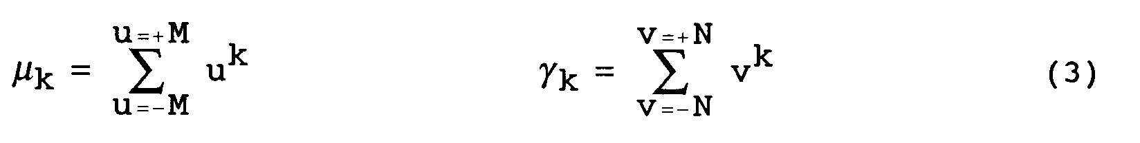
Il est possible de définir, à partir de ce qui précède, des masques dérivateurs, permettant de créer le polynôme de luminances f(uo + u, vo + v) qui est l'approximation des luminances respectives des pixels dans l'anneau d'un bloc BEi,j.It is possible to define, from the above, differentiating masks, making it possible to create the polynomial of luminances f (u o + u, v o + v) which is the approximation of the respective luminances of the pixels in the ring. of a block BE i, j .
Ces masques Kr,s, de dimension égale à la dimension d'un bloc élémentaire BEi,j, telle que (7x7), sont donnés par :
où u et v désignent les coordonnées d'un pixel dans un bloc élémentaire à estimer ;
dim désigne l'une des deux dimensions égales E ou F des deux bases polynomiales respectives pour les deux dimensions de l'image, les indices entiers r et s variant respectivement de 0 à (E-1) et 0 à (F-1) ;
(e+f) est la somme des degrés de deux polynômes P![]()
![]()
λ![]()
![]()
![]()
![]()
where u and v denote the coordinates of a pixel in an elementary block to be estimated;
dim designates one of the two equal dimensions E or F of the two respective polynomial bases for the two dimensions of the image, the whole indices r and s varying respectively from 0 to (E-1) and 0 to (F-1) ;
(e + f) is the sum of the degrees of two polynomials P ![]()
![]()
λ ![]()
![]()
![]()
![]()
Le polynôme de luminance est alors défini par :![]()
avec![]()
I(u,v) désignant la luminance d'un pixel de coordonnées (u,v).The luminance polynomial is then defined by: ![]()
with ![]()
I (u, v) designating the luminance of a pixel with coordinates (u, v).
Les deux dernières relations (5a) et (5b) sont à la base de la présente invention. L'approximation d'une image par un polynôme à deux variables est connue en soi. L'invention propose d'utiliser un tel modèle d'approximation polynomiale d'image dans le cadre d'une détection de cible.The last two relationships (5a) and (5b) are the basis of the present invention. The approximation of an image by a polynomial with two variables is known per se. The invention proposes to use such a polynomial image approximation model for target detection.
Selon la présente invention, l'approximation polynomiale de chaque bloc élémentaire de pixel est limitée aux seuls pixels de l'anneau du bloc, et les luminances ponctuelles dans le trou dudit bloc élémentaire BEi,j sont prédites à partir de cette approximation polynomiale. Ces deux étapes sont matérialisées par les circuits 2O et 21 dans la figure 2.According to the present invention, the polynomial approximation of each elementary pixel block is limited to only the pixels of the ring of the block, and the point luminances in the hole of said elementary block BE i, j are predicted from this polynomial approximation. These two stages are materialized by the
En revenant aux équations précédentes (5a) et (5b), il apparaît que le polynôme de luminance f est entièrement connu à partir des coefficients kr,s, r et s étant des entiers. Dans la relation (5a), les variables u et v désignent les abscisse et ordonnée d'un pixel, et f représente la luminance de ce pixel. Comme souligné par la relation (5b), les coefficients kr,s sont entièrement définis à partir de convolutions spatiales des masques Kr,s et des luminances des pixels du bloc considéré BEi,j. Ces masques constituent des filtres linéaires de convolution spatiale. En pratique, seuls quelques coefficients kr,s du polynôme de luminance L sont nécessaires pour estimer convenablement une luminance de pixel. Comme montré par la relation (5b), chaque coefficient du polynôme de luminance nécessite pour son calcul la définition d'un masque, ou filtre, de convolution Kr,s. L'approximation polynomiale étant réalisée selon l'invention, à partir des seuls pixels de l'anneau, dans la relation 5(b), le calcul des coefficients du polynôme de luminance ne s'effectue qu'en considérant les pixels de coordonnées (u,v) appartenant à l'anneau.Returning to the previous equations (5a) and (5b), it appears that the luminance polynomial f is entirely known from the coefficients k r, s , r and s being integers. In relation (5a), the variables u and v denote the abscissa and ordinate of a pixel, and f represents the luminance of this pixel. As underlined by equation (5b), the coefficients k r, s are entirely defined on the basis of spatial convolutions of the masks K r, s and the luminances of the pixels of the block considered BE i, j . These masks constitute linear filters of spatial convolution. In practice, only a few coefficients k r, s of the luminance polynomial L are necessary to properly estimate a pixel luminance. As shown by equation (5b), each coefficient of the luminance polynomial requires for its calculation the definition of a mask, or filter, of convolution K r, s . Since the polynomial approximation is carried out according to the invention, using only the pixels of the ring, in relation 5 (b), the calculation of the coefficients of the luminance polynomial is only carried out by considering the pixels of coordinates ( u, v) belonging to the ring.
La figure 3 illustre une réalisation pratique des circuits 2O et 21 de la figure 2, sous la forme de six filtres de convolution 2OO à 2O5 associés aux masques Kr,s, et un sommateur 2O6, tels que 0 ≦ r, s ≦ 2. Les six filtres de convolution 200 à 205 sont déduits, pour chaque bloc d'image BEi,j centré sur un pixel respectif pi,j, à partir de l'équation (4) donnée précédemment. Chaque filtre 200 à 205 reçoit des blocs élémentaires de pixels BEi,j de l'image infrarouge numérisée d'origine IO pour produire par convolution respectivement des coefficients kr,s du polynôme de luminance L, conformément à l'équation (5b). A partir de ces coefficients kr,s de polynôme est déduite, pour chaque bloc de pixels BEi,j, chacune des luminance(s) ponctuelle(s) prédites pour le(s) pixel(s) du trou dudit bloc BEi,j, en remplaçant dans l'équation (5a) les variables u et v par les rangs en terme d'abscisse et d'ordonnée du(des) pixel(s) du trou. Le sommateur 2O6 recevant des sorties des filtres de convolution 2OO à 2O5 produit en sortie, pour chaque bloc élémentaire BEi,j de l'image, une image prédite Ip constituée de(s) luminance(s) ponctuelle(s) du trou dans le bloc BEi,j prédites par approximation polynomiale.FIG. 3 illustrates a practical embodiment of the
En revenant à la figure 2, l'image prédite Ip et l'image d'origine infrarouge IO, constituée de(s) luminance(s) réelle(s) de(s) pixel(s) du trou, sont fournies à deux entrées respectives du comparateur 22. Ce dernier produit en sortie une image de différence, notée ID, représentative de la différence de luminance entre image d'origine IO et image prédite IP.Returning to FIG. 2, the predicted image Ip and the original infrared image I O , made up of real luminance (s) of pixel (s) of the hole, are provided to two respective inputs of the
Ainsi est obtenu le contraste entre un(des) luminances réelle(s) du(des) pixel(s) du trou et un(des) luminance(s) de ce trou prédite(s) à partir du modèle d'approximation polynomiale.Thus is obtained the contrast between one (of) real luminances (s) of (the) pixel (s) of the hole and one (or more) luminance (s) of this hole predicted from the polynomial approximation model.
La figure 6 montre un signal d'image de différence entre luminances prédites et réèlles de pixels de trou pour les différents blocs élémentaires BEi,j d'une image. Il apparaît que ce signal de différence de luminance fluctue autour d'une différence moyenne de luminance notée ![]()
![]()
En se reportant à la figure 2, l'image de différence ID est appliquée à une entrée du circuit de calcul de moyenne 23 qui produit la différence moyenne de luminance ![]()
![]()
![]()
![]()
![]()
![]()
![]()
![]()
![]()
![]()
En pratique, il est choisi un coefficient multiplicateur C qui est multiplié à la différence moyenne de luminance ![]()
![]()
![]()
![]()
![]()
![]()
A titre d'exemple, la figure 4 illustre une détection de cible pour un pixel central d'un trou. Sur cette figure, deux luminances d'un pixel Pi,j d'un trou respectivement indiquées en trait continu et en trait discontinu sont associées à des niveaux réel et prédit par approximation polynomiale. L'écart entre ces deux luminances déclenche une alarme dans le circuit de détection 24 s'il est supérieur au produit de la différence moyenne des luminances réelles et prédites ![]()
![]()
Claims (3)
une approximation polynomiale (20) des luminances de pixels d'un anneau dudit bloc, ledit anneau étant composé des pixels dudit bloc (BEi,j) situés à la périphérie d'un trou composé des autres pixels dudit bloc et localisé au centre dudit bloc (BEi,j),
une prédiction (21) des luminances desdits pixels du trou en fonction de ladite approximation polynomiale afin de produire des luminances prédites,
une soustraction (22) desdites luminances prédites (IP) aux luminances des pixels (IO) dudit trou, en des luminances de différence (ID), et
une détection (23,24) d'objet ponctuel dans ledit bloc (BEi,j) lorsque le rapport de l'une desdites luminances de différence (ID) relatives audit trou et d'une moyenne de luminances de différence (
a polynomial approximation (20) of the pixel luminances of a ring of said block, said ring being composed of the pixels of said block (BE i, j ) located at the periphery of a hole composed of the other pixels of said block and located in the center of said block (BE i, j ),
a prediction (21) of the luminances of said pixels of the hole as a function of said polynomial approximation in order to produce predicted luminances,
a subtraction (22) of said predicted luminances (I P ) from the luminances of the pixels (I O ) of said hole, into difference luminances (I D ), and
a detection (23,24) of point object in said block (BE i, j ) when the ratio of one of said difference luminances (I D ) relative to said hole and of an average of difference luminances (
Applications Claiming Priority (2)
| Application Number | Priority Date | Filing Date | Title |
|---|---|---|---|
| FR9215582 | 1992-12-21 | ||
| FR9215582A FR2699781B1 (en) | 1992-12-21 | 1992-12-21 | Method for detecting the appearance of point objects in an image. |
Publications (2)
| Publication Number | Publication Date |
|---|---|
| EP0604245A1 true EP0604245A1 (en) | 1994-06-29 |
| EP0604245B1 EP0604245B1 (en) | 1997-10-08 |
Family
ID=9437008
Family Applications (1)
| Application Number | Title | Priority Date | Filing Date |
|---|---|---|---|
| EP19930402677 Expired - Lifetime EP0604245B1 (en) | 1992-12-21 | 1993-10-29 | Method for detecting the appearance of dot objects in an image |
Country Status (3)
| Country | Link |
|---|---|
| EP (1) | EP0604245B1 (en) |
| DE (1) | DE69314448T2 (en) |
| FR (1) | FR2699781B1 (en) |
Cited By (5)
| Publication number | Priority date | Publication date | Assignee | Title |
|---|---|---|---|---|
| EP0893783A1 (en) * | 1997-07-24 | 1999-01-27 | Alcatel | Method of filtering digital images using a convolution kernel determined by the Savitzky-Golay method |
| FR2846448A1 (en) * | 2002-10-29 | 2004-04-30 | Thales Sa | DEVICE FOR PROCESSING RECOGNIZING IMAGES AND SELECTING LIGHT SOURCES |
| EP1679654A1 (en) * | 2005-01-11 | 2006-07-12 | STMicroelectronics (Research & Development) Limited | Improvements in digital filtering |
| US20120201448A1 (en) * | 2011-02-03 | 2012-08-09 | Seiko Epson Corporation | Robotic device, inspection device, inspection method, and inspection program |
| CN103634589A (en) * | 2012-08-22 | 2014-03-12 | 原相科技股份有限公司 | Image judgment method and object coordinate calculation device |
Citations (3)
| Publication number | Priority date | Publication date | Assignee | Title |
|---|---|---|---|---|
| US4789933A (en) * | 1987-02-27 | 1988-12-06 | Picker International, Inc. | Fractal model based image processing |
| GB2218507A (en) * | 1989-05-15 | 1989-11-15 | Plessey Co Plc | Digital data processing |
| EP0515890A2 (en) * | 1991-05-31 | 1992-12-02 | Daimler-Benz Aerospace Aktiengesellschaft | Terrain monitoring method |
-
1992
- 1992-12-21 FR FR9215582A patent/FR2699781B1/en not_active Expired - Fee Related
-
1993
- 1993-10-29 EP EP19930402677 patent/EP0604245B1/en not_active Expired - Lifetime
- 1993-10-29 DE DE1993614448 patent/DE69314448T2/en not_active Expired - Fee Related
Patent Citations (3)
| Publication number | Priority date | Publication date | Assignee | Title |
|---|---|---|---|---|
| US4789933A (en) * | 1987-02-27 | 1988-12-06 | Picker International, Inc. | Fractal model based image processing |
| GB2218507A (en) * | 1989-05-15 | 1989-11-15 | Plessey Co Plc | Digital data processing |
| EP0515890A2 (en) * | 1991-05-31 | 1992-12-02 | Daimler-Benz Aerospace Aktiengesellschaft | Terrain monitoring method |
Cited By (9)
| Publication number | Priority date | Publication date | Assignee | Title |
|---|---|---|---|---|
| EP0893783A1 (en) * | 1997-07-24 | 1999-01-27 | Alcatel | Method of filtering digital images using a convolution kernel determined by the Savitzky-Golay method |
| FR2766598A1 (en) * | 1997-07-24 | 1999-01-29 | Alsthom Cge Alcatel | PROCESS FOR FILTERING DIGITAL IMAGES BY CONVOLUTION WITH A CORE DETERMINED BY THE SAVITZKY AND GOLAY METHOD |
| FR2846448A1 (en) * | 2002-10-29 | 2004-04-30 | Thales Sa | DEVICE FOR PROCESSING RECOGNIZING IMAGES AND SELECTING LIGHT SOURCES |
| WO2004040516A1 (en) * | 2002-10-29 | 2004-05-13 | Thales | Image processing device with recognition and selection of light sources |
| US7091468B2 (en) | 2002-10-29 | 2006-08-15 | Thales | Device for image processing with recognition and selection of light sources |
| EP1679654A1 (en) * | 2005-01-11 | 2006-07-12 | STMicroelectronics (Research & Development) Limited | Improvements in digital filtering |
| US20120201448A1 (en) * | 2011-02-03 | 2012-08-09 | Seiko Epson Corporation | Robotic device, inspection device, inspection method, and inspection program |
| CN103634589A (en) * | 2012-08-22 | 2014-03-12 | 原相科技股份有限公司 | Image judgment method and object coordinate calculation device |
| CN103634589B (en) * | 2012-08-22 | 2016-08-03 | 原相科技股份有限公司 | Image judgment method and object coordinates calculate device |
Also Published As
| Publication number | Publication date |
|---|---|
| DE69314448T2 (en) | 1998-04-02 |
| FR2699781A1 (en) | 1994-06-24 |
| FR2699781B1 (en) | 1995-02-03 |
| DE69314448D1 (en) | 1997-11-13 |
| EP0604245B1 (en) | 1997-10-08 |
Similar Documents
| Publication | Publication Date | Title |
|---|---|---|
| CA2859900C (en) | Method of estimating optical flow on the basis of an asynchronous light sensor | |
| US8982363B2 (en) | Method and apparatus to determine depth information for a scene of interest | |
| EP1462992B1 (en) | System and method for shape reconstruction from optical images | |
| US20090016642A1 (en) | Method and system for high resolution, ultra fast 3-d imaging | |
| EP3221841B1 (en) | Method and device for the real-time adaptive filtering of noisy depth or disparity images | |
| EP3272119B1 (en) | Method and device of 3d reconstruction of a scene | |
| CA2801097A1 (en) | Acquisition of 3d topographic images of tool marks using non-linear photometric stereo method | |
| FR3073311A1 (en) | METHOD FOR ESTIMATING THE INSTALLATION OF A CAMERA IN THE REFERENTIAL OF A THREE-DIMENSIONAL SCENE, DEVICE, INCREASED REALITY SYSTEM, AND COMPUTER PROGRAM | |
| EP0268509B1 (en) | Process and device for the real-time optoelectronic measurement of the movements of a mobile solid structure under the effect of a fluid | |
| FR3033914A1 (en) | PROCESS FOR PROCESSING AN ASYNCHRONOUS SIGNAL | |
| US5946424A (en) | Method for reconstructing a shape and an apparatus for reconstructing a shape | |
| FR3047103A1 (en) | METHOD FOR DETECTING TARGETS ON THE GROUND AND MOVING IN A VIDEO STREAM ACQUIRED BY AN AIRBORNE CAMERA | |
| EP0604245B1 (en) | Method for detecting the appearance of dot objects in an image | |
| EP2875316B1 (en) | Method for determining parameters of water surface observation by imaging | |
| EP0577491B1 (en) | Process and device for monitoring a three-dimensional scene using imagery sensors | |
| WO2017093057A1 (en) | Method for characterising a scene by calculating the 3d orientation | |
| FR3034233A1 (en) | METHOD OF CORRECTING AN IMAGE OF AT LEAST ONE REMOTELY PRESENTED OBJECT IN FRONT OF AN IMAGER AND LIGHTING BY A LIGHTING SYSTEM AND SHOOTING SYSTEM FOR IMPLEMENTING SAID METHOD | |
| Fishbain et al. | Spatial, temporal, and interchannel image data fusion for long-distance terrestrial observation systems | |
| JPH1062154A (en) | Processing method of measured value, method and device for shape reconstruction | |
| EP3072110B1 (en) | Method for estimating the movement of an object | |
| EP1095358B1 (en) | Method for modelling three-dimensional objects or scenes | |
| Zhao et al. | 3D reconstruction and dehazing with polarization vision | |
| Song et al. | GM-APD lidar single-source data self-guided: Obtaining high-resolution depth map | |
| EP0550101A1 (en) | Image registration process | |
| EP0575208A1 (en) | Method for detecting the appearance of dot objects on a textured background |
Legal Events
| Date | Code | Title | Description |
|---|---|---|---|
| PUAI | Public reference made under article 153(3) epc to a published international application that has entered the european phase |
Free format text: ORIGINAL CODE: 0009012 |
|
| 17P | Request for examination filed |
Effective date: 19931220 |
|
| AK | Designated contracting states |
Kind code of ref document: A1 Designated state(s): DE GB IT |
|
| GRAG | Despatch of communication of intention to grant |
Free format text: ORIGINAL CODE: EPIDOS AGRA |
|
| 17Q | First examination report despatched |
Effective date: 19970122 |
|
| GRAH | Despatch of communication of intention to grant a patent |
Free format text: ORIGINAL CODE: EPIDOS IGRA |
|
| GRAH | Despatch of communication of intention to grant a patent |
Free format text: ORIGINAL CODE: EPIDOS IGRA |
|
| GRAA | (expected) grant |
Free format text: ORIGINAL CODE: 0009210 |
|
| AK | Designated contracting states |
Kind code of ref document: B1 Designated state(s): DE GB IT |
|
| RAP2 | Party data changed (patent owner data changed or rights of a patent transferred) |
Owner name: SAGEM SA |
|
| REF | Corresponds to: |
Ref document number: 69314448 Country of ref document: DE Date of ref document: 19971113 |
|
| ITF | It: translation for a ep patent filed |
Owner name: ING. PIOVESANA PAOLO |
|
| GBT | Gb: translation of ep patent filed (gb section 77(6)(a)/1977) |
Effective date: 19971107 |
|
| PLBE | No opposition filed within time limit |
Free format text: ORIGINAL CODE: 0009261 |
|
| STAA | Information on the status of an ep patent application or granted ep patent |
Free format text: STATUS: NO OPPOSITION FILED WITHIN TIME LIMIT |
|
| 26N | No opposition filed | ||
| ITPR | It: changes in ownership of a european patent |
Owner name: CAMBIO NOME EPO;SAGEM SA |
|
| REG | Reference to a national code |
Ref country code: GB Ref legal event code: IF02 |
|
| PGFP | Annual fee paid to national office [announced via postgrant information from national office to epo] |
Ref country code: GB Payment date: 20060926 Year of fee payment: 14 |
|
| PGFP | Annual fee paid to national office [announced via postgrant information from national office to epo] |
Ref country code: DE Payment date: 20060928 Year of fee payment: 14 |
|
| PGFP | Annual fee paid to national office [announced via postgrant information from national office to epo] |
Ref country code: IT Payment date: 20061031 Year of fee payment: 14 |
|
| GBPC | Gb: european patent ceased through non-payment of renewal fee |
Effective date: 20071029 |
|
| PG25 | Lapsed in a contracting state [announced via postgrant information from national office to epo] |
Ref country code: DE Free format text: LAPSE BECAUSE OF NON-PAYMENT OF DUE FEES Effective date: 20080501 |
|
| PG25 | Lapsed in a contracting state [announced via postgrant information from national office to epo] |
Ref country code: GB Free format text: LAPSE BECAUSE OF NON-PAYMENT OF DUE FEES Effective date: 20071029 |
|
| PG25 | Lapsed in a contracting state [announced via postgrant information from national office to epo] |
Ref country code: IT Free format text: LAPSE BECAUSE OF NON-PAYMENT OF DUE FEES Effective date: 20071029 |