EP0604041A2 - Call transfer with automatic return - Google Patents
Call transfer with automatic return Download PDFInfo
- Publication number
- EP0604041A2 EP0604041A2 EP93309695A EP93309695A EP0604041A2 EP 0604041 A2 EP0604041 A2 EP 0604041A2 EP 93309695 A EP93309695 A EP 93309695A EP 93309695 A EP93309695 A EP 93309695A EP 0604041 A2 EP0604041 A2 EP 0604041A2
- Authority
- EP
- European Patent Office
- Prior art keywords
- station
- call
- transfer
- return
- stations
- Prior art date
- Legal status (The legal status is an assumption and is not a legal conclusion. Google has not performed a legal analysis and makes no representation as to the accuracy of the status listed.)
- Granted
Links
Images


Classifications
-
- H—ELECTRICITY
- H04—ELECTRIC COMMUNICATION TECHNIQUE
- H04Q—SELECTING
- H04Q3/00—Selecting arrangements
- H04Q3/0016—Arrangements providing connection between exchanges
- H04Q3/002—Details
-
- H—ELECTRICITY
- H04—ELECTRIC COMMUNICATION TECHNIQUE
- H04M—TELEPHONIC COMMUNICATION
- H04M15/00—Arrangements for metering, time-control or time indication ; Metering, charging or billing arrangements for voice wireline or wireless communications, e.g. VoIP
-
- H—ELECTRICITY
- H04—ELECTRIC COMMUNICATION TECHNIQUE
- H04M—TELEPHONIC COMMUNICATION
- H04M3/00—Automatic or semi-automatic exchanges
- H04M3/42—Systems providing special services or facilities to subscribers
- H04M3/50—Centralised arrangements for answering calls; Centralised arrangements for recording messages for absent or busy subscribers ; Centralised arrangements for recording messages
- H04M3/51—Centralised call answering arrangements requiring operator intervention, e.g. call or contact centers for telemarketing
-
- H—ELECTRICITY
- H04—ELECTRIC COMMUNICATION TECHNIQUE
- H04M—TELEPHONIC COMMUNICATION
- H04M3/00—Automatic or semi-automatic exchanges
- H04M3/42—Systems providing special services or facilities to subscribers
- H04M3/58—Arrangements for transferring received calls from one subscriber to another; Arrangements affording interim conversations between either the calling or the called party and a third party
-
- H—ELECTRICITY
- H04—ELECTRIC COMMUNICATION TECHNIQUE
- H04M—TELEPHONIC COMMUNICATION
- H04M3/00—Automatic or semi-automatic exchanges
- H04M3/22—Arrangements for supervision, monitoring or testing
- H04M3/2218—Call detail recording
-
- H—ELECTRICITY
- H04—ELECTRIC COMMUNICATION TECHNIQUE
- H04M—TELEPHONIC COMMUNICATION
- H04M3/00—Automatic or semi-automatic exchanges
- H04M3/22—Arrangements for supervision, monitoring or testing
- H04M3/36—Statistical metering, e.g. recording occasions when traffic exceeds capacity of trunks
-
- H—ELECTRICITY
- H04—ELECTRIC COMMUNICATION TECHNIQUE
- H04M—TELEPHONIC COMMUNICATION
- H04M3/00—Automatic or semi-automatic exchanges
- H04M3/42—Systems providing special services or facilities to subscribers
- H04M3/50—Centralised arrangements for answering calls; Centralised arrangements for recording messages for absent or busy subscribers ; Centralised arrangements for recording messages
- H04M3/51—Centralised call answering arrangements requiring operator intervention, e.g. call or contact centers for telemarketing
- H04M3/5125—Centralised call answering arrangements requiring operator intervention, e.g. call or contact centers for telemarketing with remote located operators
Definitions
- This invention relates to telecommunications.
- One class of features relates to redirecting calls.
- a customer calls a business and the call is answered by a general customer representative.
- the representative and the customer talk for a few minutes and the representative determines that the customer should talk to a specialist.
- the representative transfers the call to the specialist. If the representative wants to talk with either the specialist or the customer at the end of the call, the representative needs to stay on the line as the customer talks to the specialist. This is wasteful of network resources, e.g., a conference bridge, but even more significantly, it wastes the representative's time.
- switch adjuncts for providing telecommunication services.
- Examples of such adjuncts include PBXs, voice mail systems, and service circuit nodes.
- the adjunct performs a role similar to that of the customer representative in the above example in that the adjunct transfers the call to a third party. If the service requires the adjunct to resume call control after the customer-specialist conversation is over, the adjunct must stay involved with the call throughout the customer-specialist conversation.
- a switch included in the adjunct provides part of the initial connection from a caller to a called party, a subsequent transfer of the call to a third party requires a continued connection through the adjunct switch even though the initial called party may not be associated with the adjunct. In all such services, both network and adjunct resources are wasted.
- a further problem is that adjuncts that provide telecommunication services over open interfaces, e.g., an ISDN basic rate interface (BRI), often do not have the high reliability or traffic bearing capacity of central switching equipment.
- BRI basic rate interface
- a transferring station can be disconnected from a call after the call is transferred to a third station, but where the call is automatically returned to the transferring station in response to either disconnect signaling or other predefined signaling, e.g., a flash or a dual-tone-multi-frequency (DTMF) tone, advantageously without requiring any station to dial the transferring station.
- the transferring station is for a subscriber to a new transfer feature referred to as a transfer-with-return.
- the feature is invoked for the call either in response to a signal from the transferring station requesting invocation of the feature or because the subscriber has only the transfer-with-return feature and no other transfer feature.
- the call is also returned in response to a busy or no answer condition of the third station.
- the initial connection may be from the calling station through the switching system, the adjunct switch, and back through the switching system to the transferring station. After the transfer, the connection need not go through the adjunct switch.
- a call processing method in accordance with the invention includes connecting a call from a first station to a second station.
- the call is then transferred from one of the first and second stations to a third station, for communication between the other of the first and second stations and the third station.
- the one station is for a subscriber to a transfer-with-return feature.
- the feature is invoked for the call.
- the one station is disconnected from the call.
- the call is automatically returned to the one station in response to a prespecified event and without receiving a dialed number for the one station.
- the invention is used in three illustrative services described herein and referred to as Services 1, 2, and 3.
- Service 1 the transferring station is for a human attendant.
- Service 2 the transferring station is a service circuit node (SCN).
- Service 3 the transferring station is an external service module (ESM).
- SCN service circuit node
- ESM external service module
- the prespecified event resulting in the automatic return could be receiving disconnect signaling from only one of the other and third stations.
- the prespecified event could also be receiving predefined signaling, e.g., a flash or DTMF tone, from one of the other and third station.
- the prespecified event could be detecting a busy or no answer condition of the third station.
- the one station In response to disconnect signaling from both the other and third stations, the one station is notified of the end of the call.
- the call transfer is effected in one of three ways: blind transfer, consultation, or conference.
- blind transfer the other station and the third station are connected without having previously connected the one station and the third station for a two-way consulation.
- consultation the one station and the third station are connected for two-way consultation and thereafter the other station and the third station are connected.
- conference the one station, the other station, and the third station are initially connected for a conference and the one station subsequently drops out.
- the one station is provided with call history information, e.g., call identification information defining the call as a return call, and defining the reason for the return, for use at the one station in answering or subsequently controlling the return call.
- call history information e.g., call identification information defining the call as a return call, and defining the reason for the return, for use at the one station in answering or subsequently controlling the return call.
- the one station may be connected back in with the other and third stations for conference as part of the automatic return.
- the one station may be connected with the other station and the third station may be connected with the other station.
- the one station is part of a group of stations, e.g, a multi-line hunt group or automatic call distributor group, that are accessible via one or more common directory numbers, the call is returned to the one station rather than any other station of the group.
- a group of stations e.g, a multi-line hunt group or automatic call distributor group
- the illustrative method may be performed by either the host system or the adjunct switch.
- a further call processing method in accordance with the invention includes connecting a call from a first station to a second station.
- the call is then transferred from one of the first and second stations to a third station, for communication between the other of the first and second stations and the third station.
- the one station is disconnected from the call.
- the previously disconnected one station is notified of the end of the call.
- 1stStation, 2ndStation, and 3rdStation are used herein to refer to stations of a calling party, called (and transferring) party, and transferred-to party, respectively.
- the 1stStation originates a call to a 2ndStation, which in turn transfers the call to a 3rdStation, establishing a talking path between the 1stStation and the 3rdStation.
- the services described herein also apply to cases where a 1stStation originates a call to a 2ndStation, the 1stStation transfers the call to a 3rdStation, establishing a talking path between the 2ndStation and the 3rdStation.
- the transferring station is also referred to as one of the first and second stations while the non-transferring station is referred to as the other of the first and second stations.
- 1stStation, 2ndStation, and 3rdStation should be read broadly as referring to customer and network equipment, telephones, computers, PBXs, and network and third-party switch adjuncts.
- This feature allows a subscribing attendant (a 2ndStation) to transfer a call (from a 1stStation) to a 3rdStation, allowing a talking path between the 1st and 3rd Stations and allowing the 2ndStation to disconnect from the call.
- a subscribing attendant a 2ndStation
- the 1stStation and 3rdStation are reconnected to the 2ndStation, if the 1st or 3rdStation signals appropriately; or the 1stStation or 3rdStation are reconnected to the 2ndStation, if the 3rdStation or 1stStation disconnects.
- the feature works as a line-subscribed feature, that can be invoked on a per-call basis or automatically invoked on all calls. If subscribed to on a per-call basis, the attendant (2ndStation) may signal transfer with no return, transfer with return, or other subscribed to attendant features, e.g., conference, hold, etc. If the attendant is part of a multi-line hunt or ACD group, the return-transfer is made to the attendant that initially handled the call. If the attendant is busy, the call is forwarded to an appropriate co-worker.
- Reconnection to the 2ndStation is triggered in several ways: disconnection by the 1st or 3rd Station, and signaling (e.g., flash or DTMF) by the 1st or 3rdStation. If the feature allows the 1stStations or 3rdStations to signal (e.g., flash or DTMF) reconnection to the attendant, then the transfer-with-return feature works in conjunction with 3-way calling.
- the 2ndStation could drop out of the conference and then be asked to come back into the conference.
- a 3rdStation may be an automated service module, e.g., a mail system. To permit the 1stStation to signal a return to the 2ndStation while disconnecting the 3rdStation, a call-termination trigger is needed.
- the transfer-with-return feature provides call-history and call-identification information in the call-setup message. It also provides a reason message that specifies the reason for the return, e.g., 3rdStation disconnected, 1stStation request, etc.
- both the 1st and 3rd Stations might disconnect before either is reconnected to the 2ndStation.
- the 2ndStation (the service attendant) might still be interested in the call history between the 1st and 3rd Stations.
- the feature permits the attendant to specify (perhaps during service subscription) whether or not they should be notified if the caller and the called party both drop the call.
- the 2ndStation(the attendant) places the 1stStation (the caller) on hold; originates a call to a 3rdStation (e.g., a service agent); conferences together the three stations; and finally disconnects the 2ndStation, leaving a talking path between the 1st and 3rd Stations.
- a 3rdStation e.g., a service agent
- the service concept also applies to other call flows.
- the 2ndStation could disconnect as soon as the call to the 3rdStation is set up but not answered, thus leaving the 1st and 3rdStations in a ringing state.
- the 2ndStation could connect to the 3rdStation for two-way consultation prior to connecting the 1stStation and 3rdStation.
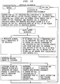
- FIG. 1 is a diagram of an exemplary network configuration.
- the 1stStation, 2ndStation and 3rdStation are connected to switches 10, 20, and 30, respectively.
- Switches 10 and 20 and switches 20 and 30 are interconnected by trunks 15 and 25, respectively, which may include intermediate switches.
- Billing center 40 and billing subsystems 41, 42, and 43 are discussed later herein with respect to Service 5.
- FIGS. 3-11 provide a state chart of how the call-with-return and call-history features operate within switching system 20 for Service 1.
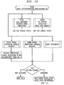
- FIG. 12 provides a summary of the state transitions.
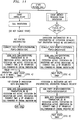
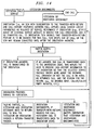
- state To improve readability, the following descriptions are partitioned by state. The notation for each state title should be read as: service concept number-state number, state name, e.g., 1-1. state Initial, indicates that Initial is the name of the first state in the state model describing service 1.
- the call flow begins in the state Initial, with the initial event, Incoming_call. This initial event initiates call processing.
- the first action taken in this state is to translate the digits dialed by the 1stStation (i.e., the caller) into a specific directory number, and to then initiate a call-setup to the 2ndStation represented by the dialed directory number.
- the 2ndStation sends an appropriate signal (e.g., a flash or DTMF), and the 2ndStation is a subscriber to the transfer-with-return feature, then place the 1stStation on hold, and transition the state model to another state, 2way_2ndStationActive.
- an appropriate signal e.g., a flash or DTMF
- the 1stStation (caller) is on hold.
- the state begins by processing the internally generated event, Initial_Event. Processing this event results in a tone!collect_digits action that delivers a stuttered tone to the 2ndStation.
- the stuttered tone prompts the 2ndStation for a feature code, one of which is transfer-with-return, another is transfer-without-return (i.e., call-transfer as it is currently done).
- the digits signaled by the 2ndStation are received as the event collected_digits. If the collected digits indicate a request for transfer-with-return, a Return_active indicator is set to true. If the transfer-with-return or -without-return feature is requested, then a second tone!collect_digits action delivers dial tone to the 2ndStation. The dial tone prompts the 2ndStation for a directory number. If a valid directory number is received from the 2ndStation, a call-setup procedure is invoked and the state model then transitions to a new state, 3way_2ndStationActive_3rdStationSetUp
- the call is returned to the previous 2-way talking path between the 1stStation and 2ndStation, and state model transitions back to the state 2way.
- appropriate signal e.g., a flash
- the call could not be connected to the designated directory number, perhaps because the 3rdStation was busy or did not answer. In this event, busy or ringing (as appropriate) is delivered to the 2ndStation.
- the state model then transitions to state 2way_2ndStationActive.
- the 3rdStation answers the call.
- the switch establishes a 2-way path between the 2nd and 3rd stations.
- the state model then transitions to an new state, 3way_2ndStationActive_3rdStationActive.
- the 2ndStation disconnects.
- the switch establishes a 2-way connection between the 1stStation and the 3rdStation. Since the 3rdStation has not yet answered, the 1stStation receives audible ringing.
- the state model then transitions to an new state, 2way_1stStationActive_3rdStationActive.
- the 2ndStation (the subscriber) signals (typically, but not necessarily, by flashing) a request to return to the 2-way call with the 1stStation. In this event, a talking path is established between the 1st and 2nd stations, and the state model transitions back to the state 2way.
- the 2ndStation has a two-way conversation with either the 1stStation or the 3rdStation.
- the 2ndStation's signal flash or DTMF acts a toggle between these two states. If the 2ndStation signals a conference request, procedures for a 3-way conversation are initiated.
- the switch opens the path between the 2nd and 3rd Stations, and connects a path between the 1st and 2nd Stations.
- the state model then transitions to a new state 3way_1stStationActive_2ndStationActive.
- the switch creates a 3-way call between the 1st, 2nd, and 3rd Stations.
- the state model then transitions to a new state 3way.
- the switch opens the path between the 1st and 2nd Stations, and connects a path between the 2nd and 3rd Stations.
- the state model then transitions back to the state 3way_2ndStationActive_3rdStationActive.
- the switch creates a 3-way call between the 1st, 2nd, and 3rd Stations.
- the state model then transitions to a new state 3way.
- connection between the 1st and 3rd station is either in a ringing state or in a talking state (depending upon whether or not the 2ndStation disconnected before or after the 3rdStation answered; or in terms of the state model, depending on whether the previous state was 3way_2ndStationActive_3rdStationSetUp or 3way).
- the 1stStation continues to hear ringing until the 1stStation signals a request to return the call to the 2ndStation, or the 1stStation disconnects. No state transition is required.
- the 3rdStation is released (disconnected) from call. If the transfer-with-return feature is active, then the state model transitions to the Return_Call state; if the feature is not active, then the call is terminated and the 1st station is disconnected.
- the state model transitions to the Return_Call state; if the feature is not active, then the call is terminated and the 3rd station is disconnected.
- the state model transitions to the Return_Call state; if the feature is not active, then the call is terminated and the remaining stations are disconnected.
- the 1st or 3rd Station disconnected or signalled a request to reconnect a talking path to the 2ndStation (the service attendant and subscriber in Service 1).
- the 2ndStation is sent an information message detailing call history information. This information allows the 2ndStation to separate new calls from return calls, to construct service bills if appropriate, or to send billing information back to the host switch.
- the state model transitions back to the state 2way and a two-way talking path is established between the 2ndStation and the remaining station.
- the call to the 2ndStation results in a 3-way call involving the 1st, 2nd, and 3rd Stations and a state model transition to the state 3way.
- the 1stStation can force a disconnect of the 3rdStation by sending the appropriate signal, e.g., a designated DTMF sequence.
- Service 2 SCN use of Transfer-with-Return feature so that SCN can be information gateway (FIG. 13)
- Service 2 The features detailed in Service 2 are the same as those specified for Service 1:
- ISDN switching system 300 is of the type disclosed in U. S. Patent 4,592,048 issued to M. W. Beckner et al. on May 27, 1986.
- Service node 400 is of the type disclosed in the AT&T A-I-NetTM Service Circuit Node (SCN) System Description and the AT&T A-I-NetTM Service Circuit Node (SCN) Product Technical Specifications Release 1, both of April 15, 1992.
- System 300 comprises a control arrangement 310, a switching network 320, and line units 330 and is connected to analog station sets 211, 212, and 213 as well as other station sets not shown.
- System 300 is also connected to service node 400 by a number of ISDN basic rate interface (BRI) lines.
- Service node 400 comprises a control computer 440, a switch fabric 420, and service circuits 430.
- Service circuits 430 provide the following capabilities: 1) digit collection, 2) tone detection/generation, 3) FAX receipt, storage, and transmittal, 4) voice recording, storage, and playback, 5) text-to-speech (TTS) announcements, 6) call setup through the switch fabric 420, 7) conference bridging, 8) transferring a call to a second party, and 9) returning call control to system 300.
- Database 500 provides a reverse white pages directory which returns a calling party name when a calling party number is provided.
- service node 200 may be connected to a plurality of ISDN switching systems in addition to system 100.
- System 300 with the transfer-with-return and call history features added, together with SCN 400 are used as switch 20 and the 2ndStation in FIG. 13.
- the features illustrated in the call flow of FIG. 14 can be used by the SCN (the 2ndStation in these examples) to transfer calls back to a host switch (thus increasing service reliability and decreasing traffic capacity), and then regain call control when the 1stStation or 2ndStation disconnects (or appropriately signals). These features also allow the SCN to act as information gateway to a variety of external service modules which are independent and which have no knowledge of the SCN.
- the number of different services supported by an SCN is very large.
- the SCN may provide an information gateway service in which user choices are communicated. As each choice is recognized, the transfer-with-return procedures executes allowing the user access to the chosen service and to return to the SCN after completing the service transaction.
- This feature allows the SCN (acting as a 2ndStation, in the current terminology) to call a 1stStation or answer a call from a 1stStation.
- the SCN may apply a multitude of service circuits to the call (as required by a particular service flow), and eventually may transfer the call to a 3rdStation (possibly an external service module (ESM)).
- ESM external service module
- the SCN signals that the call should be returned to the SCN under a variety of conditions.
- the data could be transmitted to the 3rdStations either as part of the call-setup or could be sent over a RS232 link, a X.25 network, or through the D-channel on ISDN.
- An alternative would be to transmit the data via a voice channel prior to transferring the 1stStation call to the 3rdStation.
- Reconnection to the 2ndStation ci be triggered in several ways: disconnection by the 1st or 3rd Station, signaling (e.g., flash or DTMF) by the 1st or 3rdStation. If the feature allows the 1stStations or 3rdStations to signal (e.g., flash or DTMF) reconnection to the 2ndStation, then the transfer-with-return feature can work in conjunction with 3-way calling. The 2ndStation may drop out of the conference and then be asked to come back into the conference. In some cases, a 3rdStation may be an ESM, e.g., a mail system.
- ESM e.g., a mail system.
- Some of these ESMs may not provide a method by which a caller can request the ESM to initiate a disconnect. Therefore, to permit the 1stStation to signal a return to the 2ndStation (the SCN) and disconnect the 3rdStation (the ESM) from the call, a call-termination trigger is needed.
- the switch alerts the 2ndStation (the SCN) with a call set-up message containing the caller's DN and a transaction_id (possibly the account code).
- a reason message is provided that specifies the reason for the return, e.g., 3rdStation disconnected, caller-initiated return, etc.
- the 2ndStation (the SCN) can then process the call using the appropriate customer logic, and determine the call history and billing records from internally stored data. (Note the call-history capability referred to in Service 1 could be provided through an SCN, if all call-transfers return to the SCN, or all call-history records are sent to the SCN).
- This feature allows the gateway-ESM (acting as a 2ndStation, in the current terminology) to call a 1stStation or answer a call from a 1stStation.
- the ESM can only answer and transfer calls to a 3rdStation (possibly a service-circuit or external service module (ESM)).
- ESM service-circuit or external service module
- the gateway-ESM and the 3rdStations need to communicate call-related data
- the data could be transmitted to the 3rdStation either as part of the call-setup or could be sent over a RS232 link, a X.25 network, or through the D-channel on ISDN.
- An alternative would be to transmit the data via a voice channel prior to transferring the 1stStation to the 3rdStation.
- Reconnection to the 2ndStation can be triggered in several ways: disconnection by the 1st or 3rd Station, signaling (e.g., flash or DTMF) by the 1st or 3rdStation. If the feature allows the 1stStations or 3rdStations to signal (e.g., flash or DTMF) reconnection to the 2ndStation, then the transfer-with-return feature can work in conjunction with 3-way calling. The 2ndStation may drop out of the conference and then be asked to come back into the conference. In some cases, a 3rdStation may be an ESM, e.g., a mail system.
- ESM e.g., a mail system.
- Some of these ESMs may not provide a method by which a caller can request the ESM to initiate a disconnect. Therefore, to permit the 1stStation to signal a return to the 2ndStation and disconnect the 3rdStation (e.g., a voice mail ESM) from the call, a call-termination trigger is needed.
- a call-termination trigger is needed.
- the switch alerts the 2ndStation (the gateway-ESM) with a call set-up message containing the caller's DN and a transaction_id (possibly the account code).
- a reason message is provided that specifies the reason for the return, e.g., 3rdStation disconnected, caller-initiated return, etc.
- the 2ndStation (the gateway-ESM) can then process the call using the appropriate customer logic, and determine the call history and billing records from internally stored data. (Note the call-history capability referred to in Service 1 could be provided through a gateway ESM, if all call-transfers return to the gateway-ESM, or all call-history records are sent to the gateway-ESM).
- the gateway-ESM can track service measurements and 3rdStation usage (if this important for the service).
Abstract
Description
- This invention relates to telecommunications.
- As stored program controlled switching systems have evolved, a wide variety of useful features have been developed to extend the communication capabilities such systems provide. One class of features relates to redirecting calls. Consider an example where a customer calls a business and the call is answered by a general customer representative. The representative and the customer talk for a few minutes and the representative determines that the customer should talk to a specialist. The representative then transfers the call to the specialist. If the representative wants to talk with either the specialist or the customer at the end of the call, the representative needs to stay on the line as the customer talks to the specialist. This is wasteful of network resources, e.g., a conference bridge, but even more significantly, it wastes the representative's time.
- Recent years have seen an increase in the use of switch adjuncts for providing telecommunication services. Examples of such adjuncts include PBXs, voice mail systems, and service circuit nodes. In many services, the adjunct performs a role similar to that of the customer representative in the above example in that the adjunct transfers the call to a third party. If the service requires the adjunct to resume call control after the customer-specialist conversation is over, the adjunct must stay involved with the call throughout the customer-specialist conversation. In cases where a switch included in the adjunct provides part of the initial connection from a caller to a called party, a subsequent transfer of the call to a third party requires a continued connection through the adjunct switch even though the initial called party may not be associated with the adjunct. In all such services, both network and adjunct resources are wasted. A further problem is that adjuncts that provide telecommunication services over open interfaces, e.g., an ISDN basic rate interface (BRI), often do not have the high reliability or traffic bearing capacity of central switching equipment. These deficiencies are more significant when a talking path is established through the adjunct and such path must be maintained after a call is transferred.
- These problems are solved and a technical advance is achieved in accordance with the principles of the invention in a call processing method where a transferring station can be disconnected from a call after the call is transferred to a third station, but where the call is automatically returned to the transferring station in response to either disconnect signaling or other predefined signaling, e.g., a flash or a dual-tone-multi-frequency (DTMF) tone, advantageously without requiring any station to dial the transferring station. The transferring station is for a subscriber to a new transfer feature referred to as a transfer-with-return. The feature is invoked for the call either in response to a signal from the transferring station requesting invocation of the feature or because the subscriber has only the transfer-with-return feature and no other transfer feature. The call is also returned in response to a busy or no answer condition of the third station. In an arrangement comprising a switching system connected to the transferring station, and an adjunct switch also connected to the switching system, the initial connection may be from the calling station through the switching system, the adjunct switch, and back through the switching system to the transferring station. After the transfer, the connection need not go through the adjunct switch.
- A call processing method in accordance with the invention includes connecting a call from a first station to a second station. The call is then transferred from one of the first and second stations to a third station, for communication between the other of the first and second stations and the third station. The one station is for a subscriber to a transfer-with-return feature. The feature is invoked for the call. At some point, the one station is disconnected from the call. The call is automatically returned to the one station in response to a prespecified event and without receiving a dialed number for the one station.
- The invention is used in three illustrative services described herein and referred to as
Services - The prespecified event resulting in the automatic return could be receiving disconnect signaling from only one of the other and third stations. The prespecified event could also be receiving predefined signaling, e.g., a flash or DTMF tone, from one of the other and third station. Finally, the prespecified event could be detecting a busy or no answer condition of the third station.
- In response to disconnect signaling from both the other and third stations, the one station is notified of the end of the call.
- The call transfer is effected in one of three ways: blind transfer, consultation, or conference. With blind transfer, the other station and the third station are connected without having previously connected the one station and the third station for a two-way consulation. With consultation, the one station and the third station are connected for two-way consultation and thereafter the other station and the third station are connected. With conference, the one station, the other station, and the third station are initially connected for a conference and the one station subsequently drops out.
- The one station is provided with call history information, e.g., call identification information defining the call as a return call, and defining the reason for the return, for use at the one station in answering or subsequently controlling the return call.
- The one station may be connected back in with the other and third stations for conference as part of the automatic return. Alternatively, the one station may be connected with the other station and the third station may be connected with the other station.
- If the one station is part of a group of stations, e.g, a multi-line hunt group or automatic call distributor group, that are accessible via one or more common directory numbers, the call is returned to the one station rather than any other station of the group.
- In an arrangement comprising a host switching system and an adjunct switch connected to the host system, the illustrative method may be performed by either the host system or the adjunct switch.
- A further call processing method in accordance with the invention includes connecting a call from a first station to a second station. The call is then transferred from one of the first and second stations to a third station, for communication between the other of the first and second stations and the third station. At some point, the one station is disconnected from the call. In response to disconnect signaling from both the other and the third stations, the previously disconnected one station is notified of the end of the call.
-
- FIG. 1 is a hardware diagram for an arrangement where Service 1 described herein is implemented;
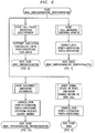
- FIG. 2 is a call flow diagram for Service 1;
- FIGS. 3-11 are action-event diagrams for a number of states used to implement the call flow for Service 1;
- FIGS. 12 is a state diagram summarizing transitions between the states of FIGS. 3-11;
- FIG. 13 is a hardware diagram for an arrangement where
Service 2 described herein is implemented; - FIG. 14 is a call flow diagram for
Service 2; - FIG. 15 is a hardware diagram for an arrangement where
Service 3 described herein is implemented; and - FIG. 16 is a call flow diagram for
Service 3. - The terms, 1stStation, 2ndStation, and 3rdStation are used herein to refer to stations of a calling party, called (and transferring) party, and transferred-to party, respectively. The 1stStation originates a call to a 2ndStation, which in turn transfers the call to a 3rdStation, establishing a talking path between the 1stStation and the 3rdStation. The services described herein also apply to cases where a 1stStation originates a call to a 2ndStation, the 1stStation transfers the call to a 3rdStation, establishing a talking path between the 2ndStation and the 3rdStation. The transferring station is also referred to as one of the first and second stations while the non-transferring station is referred to as the other of the first and second stations.
- The terms 1stStation, 2ndStation, and 3rdStation should be read broadly as referring to customer and network equipment, telephones, computers, PBXs, and network and third-party switch adjuncts.
- The following description relates to three new telephone services:
- Service 1: Attendant Service with Transfer-with-Return
In this service description, transfer-with-return and call-history features are illustrated in the context of a service center, in which customers (1stStations) call an attendant (2ndStations), who in turn can transfer the call to service specialists (3rdStations). Upon some designated signal (e.g., a flash, DTMF, or disconnect from the 1stStation or 3rdStation) the 1stStation and/or 3rdStation are reconnected to the 2ndStation. - Service 2: SCN use of Transfer-with-Return feature so that SCN can be information gateway
In this service description, the notion of an attendant (2ndStation) is generalized to include switching adjuncts, in this case, a Service Circuit Node (SCN) that can invoke the transfer-with-return and call-history features on a host switch. In such a case, the SCN is able to establish independent call legs from or to a 1stStation and a 3rdStation (the SCN acts as the 2ndStation), to apply a variety of service circuits (e.g., announcements, facsimile, and conference facilities), and to transfer the two call legs back to the host switch, so that the SCN is no longer part of the talking path between the 1stStation and 2ndStation. Upon some designated signal (e.g., a flash, DTMF, or disconnect from the 1stStation or 3rdStation) the 1stStation and/or 3rdStation are reconnected to the 2ndStation as a conference of 1st, 2nd, and 3rdStations or two call paths--a communication path between the 1st and 2ndStations and an independent communication path between the 2nd and 3rdStations. - Service 3: ESM use of Transfer-with-Return feature so that ESM can be information & service circuit gateway
In this service, a service circuit node (SCN) is generalized to less powerful service adjuncts or CPE, e.g., automated telecommunications systems referred to herein as external service modules (ESMs). - These features are used by a group of 2ndStations (e.g., a group of service attendants) to transfer calls to service agents who specialize in a particular area, and to then have the call transferred back to them for service follow-ups, quality audits, etc. Four sets of features are identified:
- transfer-with-return feature
- return transfer triggers, in particular a call-termination trigger
- call-history feature
- call-termination notification
- This feature allows a subscribing attendant (a 2ndStation) to transfer a call (from a 1stStation) to a 3rdStation, allowing a talking path between the 1st and 3rd Stations and allowing the 2ndStation to disconnect from the call. However, following the disconnection by the 2ndStation, the 1stStation and 3rdStation are reconnected to the 2ndStation, if the 1st or 3rdStation signals appropriately; or the 1stStation or 3rdStation are reconnected to the 2ndStation, if the 3rdStation or 1stStation disconnects.
- The feature works as a line-subscribed feature, that can be invoked on a per-call basis or automatically invoked on all calls. If subscribed to on a per-call basis, the attendant (2ndStation) may signal transfer with no return, transfer with return, or other subscribed to attendant features, e.g., conference, hold, etc. If the attendant is part of a multi-line hunt or ACD group, the return-transfer is made to the attendant that initially handled the call. If the attendant is busy, the call is forwarded to an appropriate co-worker.
- Reconnection to the 2ndStation is triggered in several ways: disconnection by the 1st or 3rd Station, and signaling (e.g., flash or DTMF) by the 1st or 3rdStation. If the feature allows the 1stStations or 3rdStations to signal (e.g., flash or DTMF) reconnection to the attendant, then the transfer-with-return feature works in conjunction with 3-way calling. The 2ndStation could drop out of the conference and then be asked to come back into the conference. In some cases, a 3rdStation may be an automated service module, e.g., a mail system. To permit the 1stStation to signal a return to the 2ndStation while disconnecting the 3rdStation, a call-termination trigger is needed.
- So that the 2ndStation (the service attendant) knows that the call is a previously handled call, and so that the 2ndStation is able to quickly identify which call is being returned, the transfer-with-return feature provides call-history and call-identification information in the call-setup message. It also provides a reason message that specifies the reason for the return, e.g., 3rdStation disconnected, 1stStation request, etc.
- In some call scenarios, both the 1st and 3rd Stations might disconnect before either is reconnected to the 2ndStation. In such cases, the 2ndStation (the service attendant) might still be interested in the call history between the 1st and 3rd Stations. Thus, the feature permits the attendant to specify (perhaps during service subscription) whether or not they should be notified if the caller and the called party both drop the call.
- Note that in the call flow of FIG. 2, the 2ndStation(the attendant) places the 1stStation (the caller) on hold; originates a call to a 3rdStation (e.g., a service agent); conferences together the three stations; and finally disconnects the 2ndStation, leaving a talking path between the 1st and 3rd Stations. The service concept also applies to other call flows. In particular, the 2ndStation could disconnect as soon as the call to the 3rdStation is set up but not answered, thus leaving the 1st and 3rdStations in a ringing state. Further, the 2ndStation could connect to the 3rdStation for two-way consultation prior to connecting the 1stStation and 3rdStation.
- FIG. 1 is a diagram of an exemplary network configuration. The 1stStation, 2ndStation and 3rdStation are connected to
switches Switches trunks Billing center 40 andbilling subsystems - FIGS. 3-11 provide a state chart of how the call-with-return and call-history features operate within switching
system 20 for Service 1. FIG. 12 provides a summary of the state transitions. - To improve readability, the following descriptions are partitioned by state. The notation for each state title should be read as: service concept number-state number, state name, e.g., 1-1. state Initial, indicates that Initial is the name of the first state in the state model describing service 1.
- The call flow begins in the state Initial, with the initial event, Incoming_call. This initial event initiates call processing.
- The first action taken in this state is to translate the digits dialed by the 1stStation (i.e., the caller) into a specific directory number, and to then initiate a call-setup to the 2ndStation represented by the dialed directory number.
- If the call to the 2ndStation is answered (i.e., an event answered is received from the 2ndStation), then connect 1st and 2nd Stations and transition the state model to another state, 2way.
- If the event disconnect is received from either station, then the call ends.
- If the event disconnect is received from either station, then the call ends.
- If the 2ndStation sends an appropriate signal (e.g., a flash or DTMF), and the 2ndStation is a subscriber to the transfer-with-return feature, then place the 1stStation on hold, and transition the state model to another state, 2way_2ndStationActive.
- The 1stStation (caller) is on hold.
- Several events are possible in this state:
- The state begins by processing the internally generated event, Initial_Event. Processing this event results in a tone!collect_digits action that delivers a stuttered tone to the 2ndStation. The stuttered tone prompts the 2ndStation for a feature code, one of which is transfer-with-return, another is transfer-without-return (i.e., call-transfer as it is currently done).
- The digits signaled by the 2ndStation are received as the event collected_digits. If the collected digits indicate a request for transfer-with-return, a Return_active indicator is set to true. If the transfer-with-return or -without-return feature is requested, then a second tone!collect_digits action delivers dial tone to the 2ndStation. The dial tone prompts the 2ndStation for a directory number. If a valid directory number is received from the 2ndStation, a call-setup procedure is invoked and the state model then transitions to a new state, 3way_2ndStationActive_3rdStationSetUp
- If the appropriate signal (e.g., a flash) is received by the switch from the 2ndStation, the call is returned to the previous 2-way talking path between the 1stStation and 2ndStation, and state model transitions back to the state 2way.
- NOTE: the feature may be implemented so that indicating a request for starting transfer procedures is implied by the 2ndStations's (i.e., the subscriber's) initial feature request (flash or DTMF). In this case, call flow would proceed directly from points (1) to (2) in FIG. 5.
- The 1stStation is on hold, and the 2ndStation has initiated transfer procedures. Several events are possible in this state:
- The call could not be connected to the designated directory number, perhaps because the 3rdStation was busy or did not answer. In this event, busy or ringing (as appropriate) is delivered to the 2ndStation. The state model then transitions to state 2way_2ndStationActive.
- The 3rdStation answers the call. In this case, the switch establishes a 2-way path between the 2nd and 3rd stations. The state model then transitions to an new state, 3way_2ndStationActive_3rdStationActive.
- The 2ndStation disconnects. In this event, the switch establishes a 2-way connection between the 1stStation and the 3rdStation. Since the 3rdStation has not yet answered, the 1stStation receives audible ringing. The state model then transitions to an new state, 2way_1stStationActive_3rdStationActive.
- The 2ndStation (the subscriber) signals (typically, but not necessarily, by flashing) a request to return to the 2-way call with the 1stStation. In this event, a talking path is established between the 1st and 2nd stations, and the state model transitions back to the state 2way.
- In the next two states, the 2ndStation has a two-way conversation with either the 1stStation or the 3rdStation. The 2ndStation's signal (flash or DTMF) acts a toggle between these two states. If the 2ndStation signals a conference request, procedures for a 3-way conversation are initiated.
- In this state the 1stStation is on hold, while the 2nd and 3rd Stations are connected in a talking path. Two events are significant in this state:
- If the 2ndStation signals a single flash (or some DTMF equivalent) then the switch opens the path between the 2nd and 3rd Stations, and connects a path between the 1st and 2nd Stations. The state model then transitions to a new state 3way_1stStationActive_2ndStationActive.
- If the 2ndStation signals a double-flash (or some DTMF equivalent) then the switch creates a 3-way call between the 1st, 2nd, and 3rd Stations. The state model then transitions to a new state 3way.
- In this state the 3rdStation is on hold, while the 1st and 2nd Stations are connected in a talking path. Two events are significant in this state:
- If the 2ndStation signals a single flash (or some DTMF equivalent) then the switch opens the path between the 1st and 2nd Stations, and connects a path between the 2nd and 3rd Stations. The state model then transitions back to the state 3way_2ndStationActive_3rdStationActive.
- If the 2ndStation signals a double-flash (or some DTMF equivalent) then the switch creates a 3-way call between the 1st, 2nd, and 3rd Stations. The state model then transitions to a new state 3way.
- In the 3way state, all three stations are connected together in a 3-way conference.
- If the 2ndStation disconnects, a 2-way call is created between the 1stStation and the 3rdStation and the state model transitions to state 2way_1stStationActive_3rdStationActive.
- If the 1stStation or 3rdStation disconnects, a 2 way call is created between the two remaining stations (between the 2ndStation and 3rdStation, or between the 1stStation and 2ndStation, respectively). If 3rdStation disconnects, the state model transitions back to state 2way. If the 1stStation disconnects, the state model transitions to the state 2way, but consider the 3rdStation as if it were the 1stStation (the original 1stStation is no longer part of the call), except of course, the 2ndStation is now the call originator.
- Not shown are procedures that allow the 2ndStation (the subscriber who established the 3-way conference) to request the switch to create a 2-way call between the 2ndStation and 1stStation (or between the 2ndStation and 3rd Station), while placing the 3rdStation (or 1stStation) on hold.
- In this state, the 2ndStation is not part of the call.
- Initially, the connection between the 1st and 3rd station is either in a ringing state or in a talking state (depending upon whether or not the 2ndStation disconnected before or after the 3rdStation answered; or in terms of the state model, depending on whether the previous state was 3way_2ndStationActive_3rdStationSetUp or 3way).
- Five events are significant:
- If the 3rdStation does not answer, the 1stStation continues to hear ringing until the 1stStation signals a request to return the call to the 2ndStation, or the 1stStation disconnects. No state transition is required.
- If the 3rdStation answers, then the switch establishes a talking path between the 1stStation and 3rdStation. No state transition is required.
- The 3rdStation is released (disconnected) from call. If the transfer-with-return feature is active, then the state model transitions to the Return_Call state; if the feature is not active, then the call is terminated and the 1st station is disconnected.
- If the transfer-with-return feature is active, then the state model transitions to the Return_Call state; if the feature is not active, then the call is terminated and the 3rd station is disconnected.
- If the transfer-with-return feature is active, then the state model transitions to the Return_Call state; if the feature is not active, then the call is terminated and the remaining stations are disconnected.
- Prior to this state, the 1st or 3rd Station disconnected or signalled a request to reconnect a talking path to the 2ndStation (the service attendant and subscriber in Service 1). In this state, the 2ndStation is sent an information message detailing call history information. This information allows the 2ndStation to separate new calls from return calls, to construct service bills if appropriate, or to send billing information back to the host switch.
- If the 1st or 3rd Station has disconnected and the 2ndStation answers, the state model transitions back to the state 2way and a two-way talking path is established between the 2ndStation and the remaining station.
- If neither the 1st or 3rd Station has disconnected and the 2ndStation answers, the call to the 2ndStation results in a 3-way call involving the 1st, 2nd, and 3rd Stations and a state model transition to the state 3way.
- Please note, the 1stStation can force a disconnect of the 3rdStation by sending the appropriate signal, e.g., a designated DTMF sequence.
- The features detailed in
Service 2 are the same as those specified for Service 1: - transfer-with-return feature
- return transfer triggers, in particular a call-termination trigger
- call-history feature
- call-termination notification
- An arrangement comprising an ISDN switching system 300, a service circuit node 400, and a database 500 is shown in FIG. 39. ISDN switching system 300 is of the type disclosed in U. S. Patent 4,592,048 issued to M. W. Beckner et al. on May 27, 1986. Service node 400 is of the type disclosed in the AT&T A-I-Net™ Service Circuit Node (SCN) System Description and the AT&T A-I-Net™ Service Circuit Node (SCN) Product Technical Specifications Release 1, both of April 15, 1992. System 300 comprises a control arrangement 310, a switching network 320, and line units 330 and is connected to analog station sets 211, 212, and 213 as well as other station sets not shown. System 300 is also connected to service node 400 by a number of ISDN basic rate interface (BRI) lines. Service node 400 comprises a control computer 440, a switch fabric 420, and service circuits 430. Service circuits 430 provide the following capabilities: 1) digit collection, 2) tone detection/generation, 3) FAX receipt, storage, and transmittal, 4) voice recording, storage, and playback, 5) text-to-speech (TTS) announcements, 6) call setup through the switch fabric 420, 7) conference bridging, 8) transferring a call to a second party, and 9) returning call control to system 300. Database 500 provides a reverse white pages directory which returns a calling party name when a calling party number is provided. Although not shown in FIG. 39, service node 200 may be connected to a plurality of ISDN switching systems in addition to system 100. System 300 with the transfer-with-return and call history features added, together with SCN 400 are used as
switch 20 and the 2ndStation in FIG. 13. - The features illustrated in the call flow of FIG. 14 can be used by the SCN (the 2ndStation in these examples) to transfer calls back to a host switch (thus increasing service reliability and decreasing traffic capacity), and then regain call control when the 1stStation or 2ndStation disconnects (or appropriately signals). These features also allow the SCN to act as information gateway to a variety of external service modules which are independent and which have no knowledge of the SCN.
- This permits several extensions to the basic call flow described earlier:
- 1. The call could be an in-band or out-of-band data call. This allows the concept to support both voice and data applications.
- 2. Because many automated systems can operate on multiple concurrent calls, the call flow described previously can be broadened so that the caller (the 1stStation) need not be placed on hold during the conversation between the 2ndStation (in this case, a SCN) and the 3rdStation (i.e., service agent or ESM). Instead the SCN could maintain parallel conversations with the 1stStation and the 3rdStation before establishing a talking path between the 1st and 3rd Stations. When the 1st or 3rdStation requests reconnection to the 2ndStation (i.e. the SCN) the reconnection could either be a conference including all three parties or two separate calls (1stStation to SCN, and SCN to 3rdStation). This option for reconnection may be provisioned at subscription time. In the case of the SCN, the service is provisioned to support reconnection as separate calls, because the SCN could apply its own conference circuits if necessary.
- 3. Because a SCN is used as the automated attendant, the interactions between caller and SCN could allow services in which the SCN:
- plays voice or text-to-speech announcements (e.g., service options);
- collects information that influences service behavior. For example, information might be collected via,
- dtmf digit reception,
- speech recognition,
- speaker verification,
- out-of-band signals from another switching center.
- collects information for storage and subsequent analysis, conversion, or retrieval (i.e., playback), e.g.,
- voice recording/playback
- ascii-to-fax conversion
- facsimile recording/playback
- text-to-speech conversion
- create conferences.
- The number of different services supported by an SCN is very large. For example, the SCN may provide an information gateway service in which user choices are communicated. As each choice is recognized, the transfer-with-return procedures executes allowing the user access to the chosen service and to return to the SCN after completing the service transaction.
- This feature allows the SCN (acting as a 2ndStation, in the current terminology) to call a 1stStation or answer a call from a 1stStation. The SCN may apply a multitude of service circuits to the call (as required by a particular service flow), and eventually may transfer the call to a 3rdStation (possibly an external service module (ESM)). As part of the transfer procedure, the SCN signals that the call should be returned to the SCN under a variety of conditions.
- In addition, if the SCN and the 3rdStations need to communicate call-related data, the data could be transmitted to the 3rdStations either as part of the call-setup or could be sent over a RS232 link, a X.25 network, or through the D-channel on ISDN. An alternative would be to transmit the data via a voice channel prior to transferring the 1stStation call to the 3rdStation.
- Reconnection to the 2ndStation ci be triggered in several ways: disconnection by the 1st or 3rd Station, signaling (e.g., flash or DTMF) by the 1st or 3rdStation. If the feature allows the 1stStations or 3rdStations to signal (e.g., flash or DTMF) reconnection to the 2ndStation, then the transfer-with-return feature can work in conjunction with 3-way calling. The 2ndStation may drop out of the conference and then be asked to come back into the conference. In some cases, a 3rdStation may be an ESM, e.g., a mail system. Some of these ESMs may not provide a method by which a caller can request the ESM to initiate a disconnect. Therefore, to permit the 1stStation to signal a return to the 2ndStation (the SCN) and disconnect the 3rdStation (the ESM) from the call, a call-termination trigger is needed.
- As part of the return transfer procedure, the switch alerts the 2ndStation (the SCN) with a call set-up message containing the caller's DN and a transaction_id (possibly the account code). A reason message is provided that specifies the reason for the return, e.g., 3rdStation disconnected, caller-initiated return, etc. The 2ndStation (the SCN) can then process the call using the appropriate customer logic, and determine the call history and billing records from internally stored data. (Note the call-history capability referred to in Service 1 could be provided through an SCN, if all call-transfers return to the SCN, or all call-history records are sent to the SCN).
- If the caller disconnects, then a message is sent to the 2ndStation (the SCN), so that the 2ndStation (the SCN) can track service measurements and 3rdStation usage (if this important for the service).
- The features detailed in this service are the same as those specified for Service 1:
- transfer-with-return feature
- return transfer triggers, in particular a call-termination trigger - call-history feature
- call-termination notification
- This feature allows the gateway-ESM (acting as a 2ndStation, in the current terminology) to call a 1stStation or answer a call from a 1stStation. The ESM can only answer and transfer calls to a 3rdStation (possibly a service-circuit or external service module (ESM)). As part of the transfer procedure, the gateway-ESM signals that the call should be returned to the gateway-ESM under a variety of conditions.
- In addition, if the gateway-ESM and the 3rdStations need to communicate call-related data, the data could be transmitted to the 3rdStation either as part of the call-setup or could be sent over a RS232 link, a X.25 network, or through the D-channel on ISDN. An alternative would be to transmit the data via a voice channel prior to transferring the 1stStation to the 3rdStation.
- Reconnection to the 2ndStation can be triggered in several ways: disconnection by the 1st or 3rd Station, signaling (e.g., flash or DTMF) by the 1st or 3rdStation. If the feature allows the 1stStations or 3rdStations to signal (e.g., flash or DTMF) reconnection to the 2ndStation, then the transfer-with-return feature can work in conjunction with 3-way calling. The 2ndStation may drop out of the conference and then be asked to come back into the conference. In some cases, a 3rdStation may be an ESM, e.g., a mail system. Some of these ESMs may not provide a method by which a caller can request the ESM to initiate a disconnect. Therefore, to permit the 1stStation to signal a return to the 2ndStation and disconnect the 3rdStation (e.g., a voice mail ESM) from the call, a call-termination trigger is needed.
- As part of the return transfer procedure, the switch alerts the 2ndStation (the gateway-ESM) with a call set-up message containing the caller's DN and a transaction_id (possibly the account code). A reason message is provided that specifies the reason for the return, e.g., 3rdStation disconnected, caller-initiated return, etc. The 2ndStation (the gateway-ESM) can then process the call using the appropriate customer logic, and determine the call history and billing records from internally stored data. (Note the call-history capability referred to in Service 1 could be provided through a gateway ESM, if all call-transfers return to the gateway-ESM, or all call-history records are sent to the gateway-ESM).
- If the 1stStation disconnects, then a message is sent to the 2ndStation (gateway-ESM), so that the 2ndStation. (the gateway-ESM) can track service measurements and 3rdStation usage (if this important for the service).
- Please note, in this scenario, the human attendant is replaced with an automated system. This permits several extensions to the basic call flow described earlier:
- 1. The call could be an in-band or out-of-band data call. This allows the concept to support both voice and data applications.
- 2. Because many automated systems can operate on multiple concurrent calls, the call flow described previously can be broadened so that the caller need not be placed on hold during the conversation between the automated attendant (in this case, a ESM) and the third-party (i.e., service agent or another ESM). Instead the automated attendant could maintain parallel connections with the caller and the third party before establishing a talking path between the caller and third party.
Claims (10)
- A call processing method comprising
connecting a call from a first station to a second station,
transferring said call from one of said first and second stations to a third station, for communication between the other of said first and second stations and said third station, where said one station is for a subscriber to a transfer-with-return feature,
invoking said feature for said call,
disconnecting said one station from said call, and
automatically returning said call to said one station in response to a prespecified event and without receiving a dialed number for said one station. - A call processing method as claimed in claim 1, wherein said one station is the second station and includes an adjunct switch connected to a switching system,
where said transferring includes establishing a connection between said first and third stations through said switching system but not through said adjunct switch. - A call handling method comprising
a second station receiving a call from a first station, where said second station is for a subscriber to a transfer-with-return feature,
said second station initiating a transfer of said call to a third station,
said second station signaling to invoke said feature,
said second station disconnecting from said call,
said second station receiving an automatic return of said call, said return in response to a prespecified event, said return being effected without a dialing of a number for said second station. - A call handling method comprising
a first station initiating a call to a second station, where said first station is for a subscriber to a transfer-with-return feature,
said first station initiating a transfer of said call to a third station, for communication between said second and third stations,
said first station signaling to invoke said feature for said call,
said first station disconnecting from said call,
said first station receiving an automatic return of said call, said return in response to a prespecified event, said return being effected without a dialing of a number for said first station. - A method in accordance with any of the preceding claims where said prespecified event is receiving predefined signaling from another of said stations.
- A method in accordance with any of claims 1 to 4 where said prespecified event is detecting a busy condition of said third station.
- A method in accordance with any of claims 1 to 4 where said prespecified event is detecting a no answer condition of said third station.
- A switching system comprising
a switching network, and
control means for controlling said network,
said control means being responsive to a call from a first station, for controlling said network to connect said call to a second station,
said control means being responsive to a transfer request from one of said first and second stations, said one station being for a subscriber to a transfer-with-return feature, said control means invoking said feature for said call and controlling said network to transfer said call to a third station, for communication between the other of said first and second stations and said third station,
said control means being responsive to disconnect signaling from said one station, for controlling said network to disconnect said one station from said call, and
said control means being responsive to a prespecified event and without receiving a dialed number for said one station, for controlling said network to connect said one station back into said call. - A switching system comprising
a switching network, and
control means for controlling said network,
said control means being responsive to a call from a first station, for controlling said network to connect said call to a second station,
said control means being responsive to a transfer request from one of said first and second stations, for controlling said network to transfer said call to a third station, for communication between the other of said first and second stations and said third station,
said control means being responsive to disconnect signaling from said one station, for controlling said network to disconnect said one station from said call, and
said control means being responsive to disconnect signaling from both said other and third stations, for notifying said previously disconnected one station of the end of said call. - A call processing method comprising
connecting a call from a first station to a second station,
transferring said call from one of said first and second stations to a third station, for communication between the other of said first and second stations and said third station,
disconnecting said one station from said call, and
in response to disconnect signaling from both said other and third stations, notifying said previously disconnected one station of the end of said call.
Applications Claiming Priority (2)
| Application Number | Priority Date | Filing Date | Title |
|---|---|---|---|
| US99456692A | 1992-12-21 | 1992-12-21 | |
| US994566 | 1992-12-21 |
Publications (3)
| Publication Number | Publication Date |
|---|---|
| EP0604041A2 true EP0604041A2 (en) | 1994-06-29 |
| EP0604041A3 EP0604041A3 (en) | 1994-11-30 |
| EP0604041B1 EP0604041B1 (en) | 1999-02-24 |
Family
ID=25540806
Family Applications (1)
| Application Number | Title | Priority Date | Filing Date |
|---|---|---|---|
| EP93309695A Expired - Lifetime EP0604041B1 (en) | 1992-12-21 | 1993-12-03 | Call transfer with automatic return |
Country Status (5)
| Country | Link |
|---|---|
| US (1) | US5590187A (en) |
| EP (1) | EP0604041B1 (en) |
| AT (1) | ATE176974T1 (en) |
| CA (1) | CA2102092C (en) |
| DE (1) | DE69323610T2 (en) |
Cited By (6)
| Publication number | Priority date | Publication date | Assignee | Title |
|---|---|---|---|---|
| WO1997012472A1 (en) * | 1995-09-26 | 1997-04-03 | Telefonaktiebolaget Lm Ericsson (Publ) | Method and apparatus for automatic call distribution |
| EP0806858A2 (en) * | 1996-05-07 | 1997-11-12 | Inventions, Inc. | Call center |
| US5883951A (en) * | 1996-02-19 | 1999-03-16 | Telefonaktiebolaget Lm Ericsson | Method and arrangement for untrapping an unsuccessful call |
| FR2781962A1 (en) * | 1998-07-28 | 2000-02-04 | Transnet | Distant telephone subscriber rerouting interconnection technique and control boxes where the control boxes reroute calls when responses through first path are not obtained during set period |
| EP1205062A1 (en) * | 1999-07-13 | 2002-05-15 | Intervoice Limited Partnership | System and method for packet network media redirection |
| US8351588B2 (en) | 2005-03-11 | 2013-01-08 | International Business Machines Corporation | Multi-way call connection management system |
Families Citing this family (48)
| Publication number | Priority date | Publication date | Assignee | Title |
|---|---|---|---|---|
| US5873032A (en) | 1994-04-28 | 1999-02-16 | Metro One Telecommunications, Inc. | Method and system for providing directory assistance services during attempt to complete customer or after call termination via an alphanumeric page |
| US5995826A (en) * | 1994-04-28 | 1999-11-30 | Metro One Telecommunications, Inc. | Methods for conditional tone responsive reconnection to directory assistance center |
| US5797092A (en) | 1994-04-28 | 1998-08-18 | Metro One Telecommunications, Inc. | Method for monitoring the connection between the subscriber and the destination telephone and providing directory assistance upon detection of predetermined tone |
| US6628772B1 (en) * | 1994-04-28 | 2003-09-30 | Metro One Telecommunications, Inc. | Method for providing enhanced directory assistance upon command using out-of-band signaling |
| US7110520B1 (en) * | 1994-04-28 | 2006-09-19 | Metro One Telecommunications, Inc. | Method and system for directory assistance services |
| US5854837A (en) * | 1996-01-09 | 1998-12-29 | U S West, Inc. | Method and system for providing interactive data exchange between an interactive platform and a caller |
| US5946378A (en) * | 1996-07-26 | 1999-08-31 | Ag Communication Systems Corporation | Information on hold telephony service |
| US5778059A (en) * | 1996-08-30 | 1998-07-07 | Digital Technics, Inc. | Distributed predictive and event-driven processing environment |
| US6470081B1 (en) * | 1997-04-23 | 2002-10-22 | Sprint Communications Company L.P. | Telecommunications resource connection and operation using a service control point |
| US6208723B1 (en) * | 1998-04-02 | 2001-03-27 | Ericsson Inc. | System and method for enhanced automatic recall |
| US6483898B2 (en) * | 1998-09-11 | 2002-11-19 | Ameritech Corporation | System and method for providing visual indication of caller and telephony platform information on customer premises equipment |
| US6330318B1 (en) * | 1998-09-25 | 2001-12-11 | Mci Worldcom, Inc. | Method of and system for interrupting and parking calls in a switched telecommunications network |
| KR100293992B1 (en) * | 1998-12-23 | 2001-08-07 | 윤종용 | Method for transfering call cost in private exchange system |
| US7103360B2 (en) | 1998-12-30 | 2006-09-05 | Telcordia Technologies, Inc. | Switching telephone calls between wireline and cellular telephones |
| US6208864B1 (en) | 1998-12-30 | 2001-03-27 | Telcordia Technologies, Inc. | Establishing calls and processing on-going calls in fixes and cellular networks |
| US6216005B1 (en) * | 1998-12-30 | 2001-04-10 | Telcordia Technologies, Inc. | Cellular-fixed call completion and call transfer service from a cellular network provider |
| US6937597B1 (en) * | 1999-02-26 | 2005-08-30 | Lucent Technologies Inc. | Signaling method for internet telephony |
| US6473501B1 (en) * | 1999-06-11 | 2002-10-29 | Telefonaktiebolaget L M Ericsson (Publ) | Concurrent hunt group searching methods and arrangements |
| US6611585B1 (en) * | 2000-02-15 | 2003-08-26 | Nortel Networks Limited | Method and apparatus for intelligent release link trunk |
| US6920213B2 (en) * | 2000-09-15 | 2005-07-19 | Verizon Services Corp. | Methods and apparatus for facilitating the interaction between multiple telephone and computer users |
| AUPR056200A0 (en) * | 2000-10-03 | 2000-10-26 | Telemedia Group Pty Ltd | Communication arrangement |
| JP3682767B2 (en) * | 2000-12-20 | 2005-08-10 | 株式会社エヌ・ティ・ティ・ドコモ | Transfer control system, transfer control method, and transfer control terminal |
| US6760426B2 (en) | 2001-01-05 | 2004-07-06 | Sprint Communications Company, L.P. | Method and system for handling operator calls in a communication network |
| US7376225B2 (en) * | 2001-07-27 | 2008-05-20 | Motorola, Inc. | Method for feature transfer in a telecommunication network |
| DE10142494A1 (en) * | 2001-08-30 | 2003-03-20 | Siemens Ag | Service provision method within communications network with verification that provided service can be executed at target agent system |
| US7184536B2 (en) * | 2001-09-28 | 2007-02-27 | Intel Corporation | Intelligent forwarded telephone call handling with a call answering system |
| US6980632B1 (en) * | 2001-12-28 | 2005-12-27 | At&T Corp. | Method and system for providing billing capability for a service node in an advanced intelligent network environment |
| US7106847B1 (en) | 2002-01-15 | 2006-09-12 | Sprint Communications Company L.P. | Telecommunication network that provides caller-entered information to a call destination |
| US7099449B1 (en) | 2002-01-15 | 2006-08-29 | Sprint Communications Company L.P. | Telecommunication network that provides caller-entered information to multiple call destinations |
| US7003088B1 (en) | 2002-07-11 | 2006-02-21 | Sprint Communications Company L.P. | Key to correlate a call with call-handling information |
| US7298740B2 (en) | 2002-07-11 | 2007-11-20 | Sprint Communications Company L.P. | Centralized service control for a telecommunication system |
| JP4220203B2 (en) * | 2002-09-10 | 2009-02-04 | ブラザー工業株式会社 | Phone terminal |
| US7099454B1 (en) | 2002-10-22 | 2006-08-29 | Sprint Communications Company L.P. | Caller identification in a communication system |
| US7149300B1 (en) * | 2002-11-14 | 2006-12-12 | Bellsouth Ip Corporation | Transfer function for messaging platform in public telephone system |
| US7221739B1 (en) | 2002-11-14 | 2007-05-22 | Bellsouth Intellectual Property Corporation | Callback function for messaging platform in public telephone system |
| US7127055B2 (en) | 2003-02-03 | 2006-10-24 | Sprint Communications Company L.P. | Internationally accessible communications |
| US7123711B1 (en) | 2003-03-31 | 2006-10-17 | Sprint Communications Company L.P. | Call handling system and method |
| US7103166B2 (en) * | 2003-03-31 | 2006-09-05 | Sbc Properties, L.P. | Call transfer service using service control point and service node |
| US6978002B1 (en) | 2003-05-13 | 2005-12-20 | Sprint Communications Company L.P. | Dynamic routing for a telephone conference call |
| US7076050B1 (en) | 2003-08-18 | 2006-07-11 | Sprint Communications Company L.P. | Information correlation system |
| US7170991B2 (en) * | 2003-08-25 | 2007-01-30 | Cisco Technology, Inc. | Method and system for utilizing proxy designation in a call system |
| US7315617B2 (en) * | 2003-08-25 | 2008-01-01 | Cisco Technology, Inc. | Method and system for managing calls of an automatic call distributor |
| WO2005048101A2 (en) * | 2003-11-07 | 2005-05-26 | Computer Associates Think, Inc. | Method and system for software installation |
| US8000455B1 (en) * | 2004-12-09 | 2011-08-16 | Callwave, Inc. | Methods and systems for call processing |
| US8254898B2 (en) * | 2005-02-04 | 2012-08-28 | Avaya Inc. | Message handling based on the state of a telecommunications terminal |
| US7620167B2 (en) * | 2006-09-21 | 2009-11-17 | Siemens Communications, Inc. | Apparatus to override the redirect or reject feature at an SIP end point |
| CN101217600A (en) * | 2007-01-05 | 2008-07-09 | 中兴通讯股份有限公司 | A method and device of inquiring transferring operations |
| CN101217601B (en) * | 2007-01-05 | 2012-09-05 | 中兴通讯股份有限公司 | A blind transferring operation method and device |
Citations (3)
| Publication number | Priority date | Publication date | Assignee | Title |
|---|---|---|---|---|
| US3306983A (en) * | 1963-12-20 | 1967-02-28 | Bell Telephone Labor Inc | Call transfer system |
| US3576400A (en) * | 1967-03-01 | 1971-04-27 | Int Standard Electric Corp | Call transfer circuit for phone exchange systems |
| EP0456128A2 (en) * | 1990-05-11 | 1991-11-13 | Telenorma Gmbh | Method for diverting or forwarding calls in telephone exchanges |
Family Cites Families (5)
| Publication number | Priority date | Publication date | Assignee | Title |
|---|---|---|---|---|
| US3806661A (en) * | 1972-09-29 | 1974-04-23 | Stromberg Carlson Corp | Transfer circuit |
| US3936615A (en) * | 1975-03-25 | 1976-02-03 | Stromberg-Carlson Corporation | Trunk transfer circuit |
| US4125748A (en) * | 1977-10-31 | 1978-11-14 | Bell Telephone Laboratories, Incorporated | Communication system call transfer arrangement |
| US4723273A (en) * | 1985-09-25 | 1988-02-02 | American Telephone And Telegraph Company, At&T Bell Laboratories | Discretionary call forwarding |
| US4763353A (en) * | 1986-02-14 | 1988-08-09 | American Telephone And Telegraph Company | Terminal based adjunct call manager for a communication system |
-
1993
- 1993-10-29 CA CA002102092A patent/CA2102092C/en not_active Expired - Fee Related
- 1993-12-03 EP EP93309695A patent/EP0604041B1/en not_active Expired - Lifetime
- 1993-12-03 AT AT93309695T patent/ATE176974T1/en active
- 1993-12-03 DE DE69323610T patent/DE69323610T2/en not_active Expired - Lifetime
-
1995
- 1995-04-21 US US08/427,636 patent/US5590187A/en not_active Expired - Lifetime
Patent Citations (3)
| Publication number | Priority date | Publication date | Assignee | Title |
|---|---|---|---|---|
| US3306983A (en) * | 1963-12-20 | 1967-02-28 | Bell Telephone Labor Inc | Call transfer system |
| US3576400A (en) * | 1967-03-01 | 1971-04-27 | Int Standard Electric Corp | Call transfer circuit for phone exchange systems |
| EP0456128A2 (en) * | 1990-05-11 | 1991-11-13 | Telenorma Gmbh | Method for diverting or forwarding calls in telephone exchanges |
Cited By (11)
| Publication number | Priority date | Publication date | Assignee | Title |
|---|---|---|---|---|
| WO1997012472A1 (en) * | 1995-09-26 | 1997-04-03 | Telefonaktiebolaget Lm Ericsson (Publ) | Method and apparatus for automatic call distribution |
| US5742675A (en) * | 1995-09-26 | 1998-04-21 | Telefonaktiebolaget Lm Ericsson | Method and apparatus for automatically distributing calls to available logged-in call handling agents |
| AU708730B2 (en) * | 1995-09-26 | 1999-08-12 | Telefonaktiebolaget Lm Ericsson (Publ) | Method and apparatus for automatic call distribution |
| US5883951A (en) * | 1996-02-19 | 1999-03-16 | Telefonaktiebolaget Lm Ericsson | Method and arrangement for untrapping an unsuccessful call |
| EP0806858A2 (en) * | 1996-05-07 | 1997-11-12 | Inventions, Inc. | Call center |
| EP0806858A3 (en) * | 1996-05-07 | 2000-01-05 | Inventions, Inc. | Call center |
| US6314089B1 (en) | 1996-05-07 | 2001-11-06 | Inventions, Inc. | Creating and using an adaptable multiple-contact transaction object |
| FR2781962A1 (en) * | 1998-07-28 | 2000-02-04 | Transnet | Distant telephone subscriber rerouting interconnection technique and control boxes where the control boxes reroute calls when responses through first path are not obtained during set period |
| EP1205062A1 (en) * | 1999-07-13 | 2002-05-15 | Intervoice Limited Partnership | System and method for packet network media redirection |
| EP1205062A4 (en) * | 1999-07-13 | 2002-11-13 | Intervoice Lp | System and method for packet network media redirection |
| US8351588B2 (en) | 2005-03-11 | 2013-01-08 | International Business Machines Corporation | Multi-way call connection management system |
Also Published As
| Publication number | Publication date |
|---|---|
| EP0604041B1 (en) | 1999-02-24 |
| DE69323610T2 (en) | 1999-08-12 |
| DE69323610D1 (en) | 1999-04-01 |
| US5590187A (en) | 1996-12-31 |
| CA2102092A1 (en) | 1994-06-22 |
| EP0604041A3 (en) | 1994-11-30 |
| ATE176974T1 (en) | 1999-03-15 |
| CA2102092C (en) | 1997-05-06 |
Similar Documents
| Publication | Publication Date | Title |
|---|---|---|
| EP0604041B1 (en) | Call transfer with automatic return | |
| US5517560A (en) | Call billing and measurement methods for redirected calls | |
| US5282243A (en) | Recording of automatic number identification to identify lost customers | |
| US8989365B2 (en) | Call monitoring | |
| US5309512A (en) | Call waiting deluxe feature | |
| JP3115772B2 (en) | Telephone call processing method | |
| US6754326B2 (en) | Method and apparatus for monitoring telephonic members and providing directory assistance | |
| US5875231A (en) | Telephone call on hold service for a party placed on hold by another party | |
| US7035385B2 (en) | Method and system for screening calls during voicemail messaging | |
| US8031855B2 (en) | Method for providing enhanced directory assistance upon command using out-of-band signaling | |
| US8670549B2 (en) | Method and system for improved routing of repair calls to a call center | |
| US5963620A (en) | Integrated communications control device for a small office configured for coupling within a scalable network including multiple simultaneous call capability | |
| US6614896B1 (en) | Advertising system for callers to busy numbers | |
| US6798868B1 (en) | Call notification service for use with call waiting | |
| KR980013191A (en) | Calling party identification announcement service | |
| US20040141593A1 (en) | Remote call monitoring | |
| KR19990029493A (en) | How to delay call answering | |
| US5844974A (en) | Emergency telephone communications system | |
| EP0893928B1 (en) | Method for mediation of traffic in an advanced intelligent network | |
| EP1269769B1 (en) | Computer telephony integration | |
| JP3097114B2 (en) | Service control method in communication system, telephone and facsimile apparatus | |
| GB2298761A (en) | Voice services system including a network database | |
| EP1388250B1 (en) | Services in a telephony system | |
| JPH08223291A (en) | Communication information providing system | |
| KR20010056637A (en) | Method for meet-me calling in intelligent network |
Legal Events
| Date | Code | Title | Description |
|---|---|---|---|
| PUAI | Public reference made under article 153(3) epc to a published international application that has entered the european phase |
Free format text: ORIGINAL CODE: 0009012 |
|
| AK | Designated contracting states |
Kind code of ref document: A2 Designated state(s): AT BE CH DE ES FR GB IT LI NL SE |
|
| PUAL | Search report despatched |
Free format text: ORIGINAL CODE: 0009013 |
|
| AK | Designated contracting states |
Kind code of ref document: A3 Designated state(s): AT BE CH DE ES FR GB IT LI NL SE |
|
| 17P | Request for examination filed |
Effective date: 19950518 |
|
| 17Q | First examination report despatched |
Effective date: 19970710 |
|
| GRAG | Despatch of communication of intention to grant |
Free format text: ORIGINAL CODE: EPIDOS AGRA |
|
| GRAG | Despatch of communication of intention to grant |
Free format text: ORIGINAL CODE: EPIDOS AGRA |
|
| GRAH | Despatch of communication of intention to grant a patent |
Free format text: ORIGINAL CODE: EPIDOS IGRA |
|
| GRAH | Despatch of communication of intention to grant a patent |
Free format text: ORIGINAL CODE: EPIDOS IGRA |
|
| GRAA | (expected) grant |
Free format text: ORIGINAL CODE: 0009210 |
|
| AK | Designated contracting states |
Kind code of ref document: B1 Designated state(s): AT BE CH DE ES FR GB IT LI NL SE |
|
| PG25 | Lapsed in a contracting state [announced via postgrant information from national office to epo] |
Ref country code: NL Free format text: LAPSE BECAUSE OF FAILURE TO SUBMIT A TRANSLATION OF THE DESCRIPTION OR TO PAY THE FEE WITHIN THE PRESCRIBED TIME-LIMIT Effective date: 19990224 Ref country code: LI Free format text: LAPSE BECAUSE OF FAILURE TO SUBMIT A TRANSLATION OF THE DESCRIPTION OR TO PAY THE FEE WITHIN THE PRESCRIBED TIME-LIMIT Effective date: 19990224 Ref country code: ES Free format text: THE PATENT HAS BEEN ANNULLED BY A DECISION OF A NATIONAL AUTHORITY Effective date: 19990224 Ref country code: CH Free format text: LAPSE BECAUSE OF FAILURE TO SUBMIT A TRANSLATION OF THE DESCRIPTION OR TO PAY THE FEE WITHIN THE PRESCRIBED TIME-LIMIT Effective date: 19990224 Ref country code: BE Free format text: LAPSE BECAUSE OF FAILURE TO SUBMIT A TRANSLATION OF THE DESCRIPTION OR TO PAY THE FEE WITHIN THE PRESCRIBED TIME-LIMIT Effective date: 19990224 Ref country code: AT Free format text: LAPSE BECAUSE OF FAILURE TO SUBMIT A TRANSLATION OF THE DESCRIPTION OR TO PAY THE FEE WITHIN THE PRESCRIBED TIME-LIMIT Effective date: 19990224 |
|
| REF | Corresponds to: |
Ref document number: 176974 Country of ref document: AT Date of ref document: 19990315 Kind code of ref document: T |
|
| REG | Reference to a national code |
Ref country code: CH Ref legal event code: EP |
|
| ITF | It: translation for a ep patent filed |
Owner name: JACOBACCI & PERANI S.P.A. |
|
| REF | Corresponds to: |
Ref document number: 69323610 Country of ref document: DE Date of ref document: 19990401 |
|
| ET | Fr: translation filed | ||
| NLV1 | Nl: lapsed or annulled due to failure to fulfill the requirements of art. 29p and 29m of the patents act | ||
| REG | Reference to a national code |
Ref country code: CH Ref legal event code: PL |
|
| PLBE | No opposition filed within time limit |
Free format text: ORIGINAL CODE: 0009261 |
|
| STAA | Information on the status of an ep patent application or granted ep patent |
Free format text: STATUS: NO OPPOSITION FILED WITHIN TIME LIMIT |
|
| 26N | No opposition filed | ||
| REG | Reference to a national code |
Ref country code: GB Ref legal event code: IF02 |
|
| PGFP | Annual fee paid to national office [announced via postgrant information from national office to epo] |
Ref country code: SE Payment date: 20121220 Year of fee payment: 20 Ref country code: GB Payment date: 20121220 Year of fee payment: 20 Ref country code: IT Payment date: 20121227 Year of fee payment: 20 |
|
| PGFP | Annual fee paid to national office [announced via postgrant information from national office to epo] |
Ref country code: FR Payment date: 20130130 Year of fee payment: 20 Ref country code: DE Payment date: 20121220 Year of fee payment: 20 |
|
| REG | Reference to a national code |
Ref country code: FR Ref legal event code: TP Owner name: ALCATEL-LUCENT USA INC., US Effective date: 20130823 Ref country code: FR Ref legal event code: CD Owner name: ALCATEL-LUCENT USA INC., US Effective date: 20130823 |
|
| REG | Reference to a national code |
Ref country code: DE Ref legal event code: R071 Ref document number: 69323610 Country of ref document: DE |
|
| REG | Reference to a national code |
Ref country code: GB Ref legal event code: PE20 Expiry date: 20131202 |
|
| REG | Reference to a national code |
Ref country code: GB Ref legal event code: 732E Free format text: REGISTERED BETWEEN 20140102 AND 20140108 |
|
| PG25 | Lapsed in a contracting state [announced via postgrant information from national office to epo] |
Ref country code: GB Free format text: LAPSE BECAUSE OF EXPIRATION OF PROTECTION Effective date: 20131202 Ref country code: DE Free format text: LAPSE BECAUSE OF EXPIRATION OF PROTECTION Effective date: 20131204 |
|
| REG | Reference to a national code |
Ref country code: SE Ref legal event code: EUG |
|
| REG | Reference to a national code |
Ref country code: GB Ref legal event code: 732E Free format text: REGISTERED BETWEEN 20140109 AND 20140115 |
|
| REG | Reference to a national code |
Ref country code: FR Ref legal event code: GC Effective date: 20140410 |
|
| REG | Reference to a national code |
Ref country code: FR Ref legal event code: RG Effective date: 20141015 |