EP0601814B1 - Disc recording and/or reproducing apparatus having a buffer memory - Google Patents
Disc recording and/or reproducing apparatus having a buffer memory Download PDFInfo
- Publication number
- EP0601814B1 EP0601814B1 EP93309741A EP93309741A EP0601814B1 EP 0601814 B1 EP0601814 B1 EP 0601814B1 EP 93309741 A EP93309741 A EP 93309741A EP 93309741 A EP93309741 A EP 93309741A EP 0601814 B1 EP0601814 B1 EP 0601814B1
- Authority
- EP
- European Patent Office
- Prior art keywords
- data
- memory
- recording
- disc
- input
- Prior art date
- Legal status (The legal status is an assumption and is not a legal conclusion. Google has not performed a legal analysis and makes no representation as to the accuracy of the status listed.)
- Expired - Lifetime
Links
- 239000000872 buffer Substances 0.000 title description 58
- 238000000034 method Methods 0.000 claims description 17
- 238000013144 data compression Methods 0.000 claims description 8
- 230000004044 response Effects 0.000 claims description 5
- 230000003287 optical effect Effects 0.000 description 81
- 238000007906 compression Methods 0.000 description 15
- 230000006835 compression Effects 0.000 description 15
- 230000005236 sound signal Effects 0.000 description 13
- 230000000694 effects Effects 0.000 description 5
- 230000007246 mechanism Effects 0.000 description 5
- 239000000758 substrate Substances 0.000 description 5
- 238000006243 chemical reaction Methods 0.000 description 4
- 230000001681 protective effect Effects 0.000 description 4
- 238000000547 structure data Methods 0.000 description 4
- 238000001514 detection method Methods 0.000 description 3
- 239000010408 film Substances 0.000 description 3
- 201000009310 astigmatism Diseases 0.000 description 2
- 238000010586 diagram Methods 0.000 description 2
- 230000002411 adverse Effects 0.000 description 1
- 230000006837 decompression Effects 0.000 description 1
- 230000007812 deficiency Effects 0.000 description 1
- 239000000284 extract Substances 0.000 description 1
- 239000004973 liquid crystal related substance Substances 0.000 description 1
- 230000005415 magnetization Effects 0.000 description 1
- 239000000463 material Substances 0.000 description 1
- 229920000515 polycarbonate Polymers 0.000 description 1
- 239000004417 polycarbonate Substances 0.000 description 1
- 238000013139 quantization Methods 0.000 description 1
- 229920005989 resin Polymers 0.000 description 1
- 239000011347 resin Substances 0.000 description 1
- 238000005070 sampling Methods 0.000 description 1
- 239000004065 semiconductor Substances 0.000 description 1
- 238000004544 sputter deposition Methods 0.000 description 1
- 229920003002 synthetic resin Polymers 0.000 description 1
- 239000000057 synthetic resin Substances 0.000 description 1
- 239000010409 thin film Substances 0.000 description 1
- 238000007738 vacuum evaporation Methods 0.000 description 1
- 238000012795 verification Methods 0.000 description 1
- 230000000007 visual effect Effects 0.000 description 1
Images

Classifications
-
- G—PHYSICS
- G11—INFORMATION STORAGE
- G11B—INFORMATION STORAGE BASED ON RELATIVE MOVEMENT BETWEEN RECORD CARRIER AND TRANSDUCER
- G11B20/00—Signal processing not specific to the method of recording or reproducing; Circuits therefor
- G11B20/00007—Time or data compression or expansion
-
- G—PHYSICS
- G11—INFORMATION STORAGE
- G11B—INFORMATION STORAGE BASED ON RELATIVE MOVEMENT BETWEEN RECORD CARRIER AND TRANSDUCER
- G11B19/00—Driving, starting, stopping record carriers not specifically of filamentary or web form, or of supports therefor; Control thereof; Control of operating function ; Driving both disc and head
- G11B19/02—Control of operating function, e.g. switching from recording to reproducing
-
- G—PHYSICS
- G11—INFORMATION STORAGE
- G11B—INFORMATION STORAGE BASED ON RELATIVE MOVEMENT BETWEEN RECORD CARRIER AND TRANSDUCER
- G11B20/00—Signal processing not specific to the method of recording or reproducing; Circuits therefor
- G11B20/10—Digital recording or reproducing
- G11B20/10527—Audio or video recording; Data buffering arrangements
-
- G—PHYSICS
- G11—INFORMATION STORAGE
- G11B—INFORMATION STORAGE BASED ON RELATIVE MOVEMENT BETWEEN RECORD CARRIER AND TRANSDUCER
- G11B20/00—Signal processing not specific to the method of recording or reproducing; Circuits therefor
- G11B20/10—Digital recording or reproducing
- G11B20/18—Error detection or correction; Testing, e.g. of drop-outs
- G11B20/1833—Error detection or correction; Testing, e.g. of drop-outs by adding special lists or symbols to the coded information
-
- G—PHYSICS
- G11—INFORMATION STORAGE
- G11B—INFORMATION STORAGE BASED ON RELATIVE MOVEMENT BETWEEN RECORD CARRIER AND TRANSDUCER
- G11B27/00—Editing; Indexing; Addressing; Timing or synchronising; Monitoring; Measuring tape travel
- G11B27/02—Editing, e.g. varying the order of information signals recorded on, or reproduced from, record carriers
- G11B27/031—Electronic editing of digitised analogue information signals, e.g. audio or video signals
- G11B27/034—Electronic editing of digitised analogue information signals, e.g. audio or video signals on discs
-
- G—PHYSICS
- G11—INFORMATION STORAGE
- G11B—INFORMATION STORAGE BASED ON RELATIVE MOVEMENT BETWEEN RECORD CARRIER AND TRANSDUCER
- G11B27/00—Editing; Indexing; Addressing; Timing or synchronising; Monitoring; Measuring tape travel
- G11B27/10—Indexing; Addressing; Timing or synchronising; Measuring tape travel
- G11B27/34—Indicating arrangements
-
- G—PHYSICS
- G11—INFORMATION STORAGE
- G11B—INFORMATION STORAGE BASED ON RELATIVE MOVEMENT BETWEEN RECORD CARRIER AND TRANSDUCER
- G11B20/00—Signal processing not specific to the method of recording or reproducing; Circuits therefor
- G11B20/10—Digital recording or reproducing
- G11B20/10527—Audio or video recording; Data buffering arrangements
- G11B2020/1062—Data buffering arrangements, e.g. recording or playback buffers
- G11B2020/10629—Data buffering arrangements, e.g. recording or playback buffers the buffer having a specific structure
- G11B2020/10666—Ring buffers, e.g. buffers wherein an iteratively progressing read or write pointer moves back to the beginning of the buffer when reaching the last storage cell
-
- G—PHYSICS
- G11—INFORMATION STORAGE
- G11B—INFORMATION STORAGE BASED ON RELATIVE MOVEMENT BETWEEN RECORD CARRIER AND TRANSDUCER
- G11B2220/00—Record carriers by type
- G11B2220/20—Disc-shaped record carriers
- G11B2220/21—Disc-shaped record carriers characterised in that the disc is of read-only, rewritable, or recordable type
- G11B2220/211—Discs having both read-only and rewritable or recordable areas containing application data; Partial ROM media
-
- G—PHYSICS
- G11—INFORMATION STORAGE
- G11B—INFORMATION STORAGE BASED ON RELATIVE MOVEMENT BETWEEN RECORD CARRIER AND TRANSDUCER
- G11B2220/00—Record carriers by type
- G11B2220/20—Disc-shaped record carriers
- G11B2220/21—Disc-shaped record carriers characterised in that the disc is of read-only, rewritable, or recordable type
- G11B2220/213—Read-only discs
-
- G—PHYSICS
- G11—INFORMATION STORAGE
- G11B—INFORMATION STORAGE BASED ON RELATIVE MOVEMENT BETWEEN RECORD CARRIER AND TRANSDUCER
- G11B2220/00—Record carriers by type
- G11B2220/20—Disc-shaped record carriers
- G11B2220/21—Disc-shaped record carriers characterised in that the disc is of read-only, rewritable, or recordable type
- G11B2220/215—Recordable discs
- G11B2220/218—Write-once discs
-
- G—PHYSICS
- G11—INFORMATION STORAGE
- G11B—INFORMATION STORAGE BASED ON RELATIVE MOVEMENT BETWEEN RECORD CARRIER AND TRANSDUCER
- G11B2220/00—Record carriers by type
- G11B2220/20—Disc-shaped record carriers
- G11B2220/25—Disc-shaped record carriers characterised in that the disc is based on a specific recording technology
- G11B2220/2525—Magneto-optical [MO] discs
-
- G—PHYSICS
- G11—INFORMATION STORAGE
- G11B—INFORMATION STORAGE BASED ON RELATIVE MOVEMENT BETWEEN RECORD CARRIER AND TRANSDUCER
- G11B2220/00—Record carriers by type
- G11B2220/20—Disc-shaped record carriers
- G11B2220/25—Disc-shaped record carriers characterised in that the disc is based on a specific recording technology
- G11B2220/2537—Optical discs
- G11B2220/2545—CDs
Description
- The present invention relates to a disc recording method and a disc recording apparatus whereby audio data is recorded and reproduced. More particularly, the invention relates to a method of and an apparatus for recording data on the disc, the apparatus having a memory in which to store temporarily the data preparatory to recording onto the disc.
- In general, audio signal recording apparatuses such as tape recorders do not start their actual recording operation at exactly the time when they are given a recording start instruction illustratively by operation of a recording button. This is because it takes time for the mechanisms of the recording apparatus to start up or for them to switch from another mode to recording mode. That is, the recording of data onto the storage medium actually begins after a delay of a certain period of time. In other words, no audio signal can be recorded during that delay time onto the storage medium, with the result that the initial part of a conversation or other sound sequence to be recorded may fail to register on the storage medium.
- An example is the tape recorder for conference recording purposes disclosed in Japanese Patent Laid-Open No. SHO/60-195753 (1985). This tape recorder is designed to be inactive while no sound is detected and to activate recording only when it detects sound. This kind of tape recorder is incapable of recording an initial part of a sound sequence due to the time of delay from detection of the sound sequence until the actual start of the mechanisms for recording.
- One solution to the above deficiency is proposed in the form of a recording apparatus disclosed in Japanese Patent Laid-Open No. SHO/58-41453 (1983). This recording apparatus comprises a FIFO memory with a recording capacity large enough to accommodate that initial part of a sound sequence which corresponds to a predetermined start-up time of the apparatus mechanisms. That is, the FIFO memory stores an amount of audio data equivalent to the start-up time, the audio data being handled through the memory as part of the actual data to be recorded.
- One disadvantage of the above recording apparatus is the inclusion of the FIFO memory that is provided specifically to prevent omission of the initial part of the sound sequence. The memory is expensive and requires space in the apparatus which in turn needs to be bulkier than other models.
- Furthermore, when listeners of radio broadcasts want to record a program from the radio, they generally operate the recording button of the recording apparatus while listening to the program broadcast. In such cases, it often happens that the listeners realize that a particular program or a portion of it they have just heard should have been recorded. By the time they realize what they have missed, the program has already been broadcast and therefore irretrievable. If it is desired to record that chronologically preceding part of broadcast upon subsequent recognition thereof, the recording apparatus would need to be equipped with a FIFO memory of relatively large capacity to store a certain length of broadcast. However, the above-mentioned conventional recording apparatus fails to foresee such eventualities and has a FIFO memory only large enough to allow for the time of mechanical delay from execution of a recording start instruction until the actual start of recording operation. Whereas radio listeners have the above-mentioned need to record desired programs intact from the beginning, the conventional recording apparatus fails to meet the requirement despite its FIFO memory. Furthermore, installing a large capacity memory, which is expensive and bulky, is not a practical solution to the problem.
- EP-A-0,473,305, on which the two-part form of claim 1 is based, discloses a disc recording apparatus comprising: an encoder for subjecting an input digital signal to data compression; a memory for temporarily storing compressed data output from said encoder and having a storage capacity large enough to accommodate an amount of compressed data corresponding to a period of time from when a track jump occurs until the recording position is corrected; a head device for recording onto a disc the data read from said memory; and a controller operative to control reading and writing of data to and from said memory, wherein the speed at which data is read from said memory for recordal is higher than the speed at which data is written to the memory from said encoder, and, during normal recording of data onto said disc, the points in the memory at which data is read and written are controlled such that: compressed data is written to the memory and, when the quantity of data stored in the memory exceeds a predetermined level, data is read from the memory for recordal and, when it is detected that a track jump has occurred, compressed data is continuously written into the memory and data reading from the memory ceases, without cessation of writing of compressed data into the memory, until the recording position is corrected at which point data reading from the memory resumes.
- JP-A-4,351,748 discloses an intermittent recorder for compressed audio data comprising an encoder for subjecting an input digital signal to data compression; a memory for temporarily storing compressed data output from said encoder; and a head device for recording onto a disc the data read from said memory. When the device is energised, there is continuously written to said memory the compressed data of an input digital signal which is input over a period of time before said head device starts recording data onto the disc. When the recording mode is subsequently set, stored data of a certain period of time before setting the recording mode is read out from the memory.
- According to a first aspect of the present invention, there is provided a disc recording apparatus comprising: an encoder for subjecting an input digital signal to data compression; a memory for temporarily storing compressed data output from said encoder and having a storage capacity large enough to accommodate an amount of compressed data corresponding to a period of time from when a track jump occurs until the recording position is corrected; a head device for recording onto a disc the data read from said memory; and a controller operative to control reading and writing of data to and from said memory, wherein the speed at which data is read from said memory for recordal is higher than the speed at which data is written to the memory from said encoder, and, during normal recording of data onto said disc, the points in the memory at which data is read and written are controlled such that compressed data is written to the memory and when the quantity of data stored in the memory exceeds a predetermined level data is read from the memory for recordal; and, when it is detected that a track jump has occurred, compressed data is continuously written into the memory and data reading from the memory ceases, without cessation of writing of compressed data into the memory, until the recording position is corrected at which point data reading from the memory resumes, characterised in that: before said head device starts recording data onto said disc, compressed data from said encoder is continuously written to said memory without data being read from said memory, the point to which data is written being controlled such that the memory stores data of an input digital signal which is input over a period of time corresponding to the storage capacity of said memory; and when said head device starts recording data onto said disc in response to an input recording start instruction, data is read from said memory starting from the point in the memory at which is stored the compressed data of an input digital signal from an earlier point in time chronologically preceding the point in time at which said recording start instruction is input and the data is read at said higher speed until the quantity of data stored in said memory is reduced to said predetermined level whereupon said normal recording of data is carried out.
- According to a second aspect of the present invention, there is provided a disc recording method comprising the steps of: subjecting an input digital signal to data compression; temporarily storing the compressed data in a memory having a storage capacity large enough to accommodate an amount of an amount of compressed data corresponding to a period of time from when a track jump occurs until the recording position is corrected; recording the data read from said memory onto a disc in a predetermined recording units; and during normal recording of data onto said disc, controlling the points in the memory at which data is read and written such that: compressed data is written to the memory and, when the quantity of data stored in the memory exceeds a predetermined level, data is read from the memory for recordal at a speed higher than the speed at which data is written to the memory from said encoder; and, when it is detected that a track jump has occurred, compressed data is continuously written into the memory and data reading from the memory, without cessation of writing of compressed data into the memory, until the recording position is corrected at which point data reading from the memory resumes, characterised by further comprising the steps of: when a prerecording made is established and before said head device starts recording data onto said disc, continuously writing compressed data from said encoder to said memory without reading data from said memory, the point to which data is written being controlled such that the memory stores data of an input digital signal which is input over a period of time corresponding to the storage capacity of said memory; and when said head device starts recording data onto said disc in response to an input recording start instruction, reading data from said memory starting from the point in the memory at which is stored the compressed data of an input digital signal from an earlier point in time chronologically preceding the point in time at which said recording start instruction is input, at said higher speed until quantity of data stored in said memory is reduced to said predetermined level and then carrying out said normal recording of data.
- Thus in the described embodiments of the present invention, the following occurs. The encoder subjects an input digital signal to data compression. The memory accommodates temporarily the data that is output by the encoder. The head device records onto the disc the data read from the memory. The controller controls the memory and the head device in operation. The controller controls the operation of reading data from the memory in such a manner that the speed at which to read data from the memory is kept higher than the speed at which to write data to the memory after output from the encoder. When prerecording mode is established, the controller, before having the head device start recording data onto the disc, always writes to the memory the digital data that is input over a period of time starting from a given point in time, the period of time corresponding to the storage capacity of the memory. When having the head device start recording data onto the disc, always writes to the memory the digital data that is input over a period of time starting from a given point in time, the period of time corresponding to the storage capacity of the memory. When having the head device start recording data onto the disc in accordance with an actually input recording start instruction, the controller reads data from the memory starting from a point in time chronologically preceding the point in time at which the recording start instruction is input.
- As outlined above and according to the disc recording apparatus or method of the invention, the input data is compressed and stored temporarily in a memory before being recorded onto the disc. Through retrieval from the temporary memory, the data is recorded onto the disc starting from the time previous to the actual start of recording operation. This eliminates the possibility of failing to record the initial part of the sound sequence to be recorded.
- Any suitable form of compression may be used by the encoder.
- The invention will be further described by way of non-limitative example with reference to the accompanying drawings, in which:-
- Fig. 1 is a principal block diagram of a disc recording and reproducing apparatus embodying the present invention.
- Fig. 2 is a view of a front panel that is part of the disc recording and reproducing apparatus embodying the invention.
- Fig. 3 is a flowchart of key steps constituting a disc recording method embodying the invention.
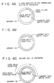
- Figs. 4A through 4C are schematic views illustrating how the writing and the reading of data to and from the memory of the inventive apparatus are controlled. Fig. 4A showing how data is written to the memory when prerecording mode is set. Fig. 4B depicting how data is overwritten to the memory. Fig. 4C portraying how data is read from the memory when prerecording mode is set.
- Fig. 5 is a view illustrating the recording operation of the disc recording and reproducing apparatus embodying the invention.
- Preferred embodiments of the invention as it is applied to an optical disc recording and reproducing apparatus will now be described in detail with reference to the accompanying drawings.
- Fig. 1 is a principal block diagram of the disc recording and reproducing apparatus embodying the present invention. In Fig. 1, reference numeral 1 is a disc cartridge that includes a cartridge proper 1A containing an optical disc 1B which is about 64 mm in diameter. There are three kinds of optical disc 1B: a read-only optical disc, a magneto-optical disc, and a hybrid disc that mixes a read-only area with a writable area. The description that follows presupposes that the optical disc 1B is a magneto-optical disc.
- The optical disc 1B has spiral pre-grooves formed thereon for light beam tracking control. With this embodiment, the pre-grooves are recorded in frequency-modulated fashion based on absolute address data. Thus the pre-grooves on the optical disc 1B wobble in the radial direction in accordance with the absolute address data given.
- The optical disc 1B includes an optically transparent disc substrate, a recording layer and a protective film. The disc substrate is composed illustratively of an optically transparent synthetic resin such as polycarbonate. The above-mentioned wobbled pre-grooves are formed beforehand on one side surface of the disc substrate. The recording layer is made of an optical recording material such as a perpendicular magnetic recording medium. This recording layer is deposited in the form of a thin film by sputtering or by vacuum evaporation over that side of the disc substrate which has the pre-grooves. Over the recording layer is the protective film made of an ultraviolet-cured resin for protective purposes.
- The optical disc 1B has a recording area and an index area. In the recording area, data is recorded along the wobbled pre-grooves. The index area accommodates title and address information. The title information includes the titles of data records, title of the disc and other titular information representing the data stored in the recording area. The address information includes the starting and end addresses and other address-related information about the data recorded on the optical disc. The index area is located radially inside the outer disc portion accommodating the recording area on the optical disc 1B. The index area is read by an optical pickup, to be described later, when the optical disc 1B is loaded in the disc recording and reproducing apparatus and before data is written to the recording area or before record data is read therefrom. The index information thus retrieved is held within a memory area of a system controller, to be described later, or within a dedicated memory area furnished in a buffer memory, to be described later.
- The disc cartridge 1 has a shutter, not shown, which is slidable mounted on the cartridge main body 1A of the disc cartridge 1. The shutter is moved between a first position and a second position. When the disc cartridge 1 is loaded in the disc recording and reproducing apparatus, the shutter is moved to the first position that an opening formed on the cartridge main body 1A is opened. When the disc cartridge 1 is ejected from the disc recording and reproducing apparatus, the shutter is moved to the second position that the opening of the cartridge main body 1A is closed.
-
Reference numeral 2 is a spindle motor that rotates the optical disc 1B at a constant linear velocity (CLV). At an edge of the rotating shaft of thespindle motor 2 is a turntable, not shown. On this turntable, the optical disc 1B of the optical cartridge 1 is placed when the cartridge 1 is loaded in the disc recording and reproducing apparatus. - Reference numeral 3 is a magnetic head located opposite to one of two openings of the disc cartridge 1. In operation, the magnetic head 3 generates a vertical magnetic field modulated in accordance with the record data fed from a head driving circuit, to be described later. The vertical magnetic field thus generated is applied to the recording layer on the optical disc 1B via the protective film.
-
Reference numeral 4 is an optical pickup located opposite to the magnetic head 3 with the optical disc 1B interposed therebetween. Theoptical pickup 4 includes a light beam source such as a semiconductor laser device, an objective lens that focuses the light beam from the light source onto the optical disc 1B, a photodetector that receives the light beam reflected by the optical disc 1B, and an optical system associated with these components. - The
optical pickup 4 further includes an actuator that drives the objective lens in the focusing and tracking directions. The actuator is supplied with a focusing servo signal and a tracking servo signal from a servo control circuit, to be described later. Under control of the servo control circuit, the actuator drives the objective lens in the focusing and tracking directions in such a manner that the focusing and tracking servo signals received by the actuator will become zero each. Theoptical pickup 4 and the magnetic head 3 are mechanically connected. When theoptical pickup 4 is moved in the radial direction over the optical disc 1B, the magnetic head 3 is also moved in the radial direction over the disc 3. The intensity of the light beam emitted by theoptical pickup 4 is controlled by a system controller, to be described later. -
Reference numeral 5 is a servo control circuit that is supplied such error signals as a focusing error signal and a tracking error signal from an RF amplifier, to be described later. Given the error signals, theservo control circuit 5 in turn generates a focusing servo signal, a tracking servo signal, a spindle servo signal and a feed signal. The focusing servo signal and tracking servo signal are fed to the actuator of theoptical pickup 4, as already mentioned. The spindle servo signal is supplied to thespindle motor 2 so that themotor 2 will turn the optical disc 1B at a constant linear velocity. The feed signal is sent to afeed motor 6. On receiving the feed signal, thefeed motor 6 generates a driving force that actuates a feed mechanism, not shown. The feed mechanism moves theoptical pickup 4 and magnetic head 3 radially along recording tracks of the optical disc 1B in recording mode or in reproducing mode. When thefeed motor 6 is supplied with an access signal based on an access instruction generated by a system controller, to be described later, thefeed motor 6 causes theoptical pickup 4 and the magnetic head 3 to effect a track jump radially over the optical disc 1B. -
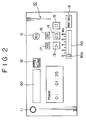
Reference numeral 10 is an input unit connected to the system controller, to be described later. As shown in Fig. 2, theinput unit 10 has a plurality of keys. More specifically, theinput unit 10 comprises a power key 11, aneject key 12, aplayback key 13, apause key 14, astop key 15, arecord key 16, a fast-forward key 17, a fast-rewind key 18 and aprerecord key 19. The power key 11 turns on and off the power source of the disc recording and reproducing apparatus when operated. Theeject key 12 is used to eject the disc cartridge 1 from the apparatus it is loaded in. The playback key 13 starts the reproducing operation of the apparatus when operated. The pause key 14 sets a pause state while the optical disc 1B is being reproduced. Operating the stop key 15 stops the disc recording and reproducing operations of the apparatus. Therecord key 16 is used to start the recording operation of the apparatus. When operated, the fast-forward key 17 and fast-rewind key 18 forward and rewind fast the reproducing position on the optical disc 1B, respectively, during reproducing operation. Theprerecord key 19 is used to set prerecording mode, to be described later. The prerecording mode set by theprerecord key 19 is a mode in which data is recorded starting from a point in time earlier than the time when therecord key 16 is operated to start the recording operation. To utilize prerecording mode requires operating the prerecord key 19 before therecord key 16. - As shown in Fig. 2, the front panel of the apparatus includes a
variable input part 50 that is used to set a prerecording time in prerecording mode, i.e., a period of time in which input data chronologically preceding the present time is recorded. Thevariable input part 50 may illustratively be a slide rheostat depicted in Fig. 2. Moving theslide lever 50a of the slide rheostat allows thevariable input part 50 to set a desired prerecording time. The prerecording time thus established reflects the resistance value of the slide rheostat converted from analog to digital format, the converted value being fed to the system controller. An A/D converter is interposed as needed between thevariable input part 50 and the system controller for conversion of the resistance value of the slide rheostat to a digital signal. If the system controller is constituted by a microcomputer incorporating an A/D converter, the separate A/D converter interposed between thevariable input part 50 and the system controller is unnecessary and will be omitted. If the storage capacity of a buffer memory, to be described later, is 4 Mbits, an audio signal chronologically preceding the present time by up to 10 seconds may be recorded. In that case, the prerecording time may be set anywhere between 0 and 10 seconds on thevariable input part 50. The prerecording mode will be described later in more detail. -
Reference numeral 20 is a system controller constituted by a microcomputer. In accordance with the key operations made on theinput unit 10, thesystem controller 20 generates control signals that are sent to relevant parts of the disc recording and reproducing apparatus for operation control. Adisplay unit 30 is connected to thesystem controller 20. Thedisplay unit 30 may be a liquid crystal display (LCD), a vacuum fluorescent display (VFD) or the like. In keeping with the signal fed from thesystem controller 20, thedisplay unit 30 displays such information as the total playback time of the optical disc 1B, the elapsed time of the program being reproduced, the remaining time of the currently reproduced program, the total remaining time of the disc, and the track number of the program being reproduced. If the optical disc 1B contains such title information as the disc title and the titles of individual programs stored, these titles are displayed selectively on thedisplay unit 30. If the optical disc 1B includes date information about the dates and times of day at which the disc or individual programs were recorded, this information is also displayed selectively on thedisplay unit 30. -
Reference numeral 31 is an input terminal through which analog signals such as an analog audio signal are input. Although Fig. 1 shows a single-channel setup for the sake of visual simplicity, there is usually provided a two-channel (L, R) stereophonic arrangement. The same holds for the description that follows. - An analog input signal that enters the input terminal is sent to an analog-to-digital (A/D)
converter 32. The A/D converter 32 digitizes the analog input signal at a sampling frequency of 44.1 kHz with a quantization bit count of 16 bits. The digital signal output from the A/D converter 32 is sent to a audio compression encoder-decoder circuit 33. The audio compression encoder-decoder circuit 33 compresses the received digital signal to about one fifth of the original. The compression technique applied in the audio compression encoder-decoder circuit 33 is a modified DCT (Discrete Cosine Transform). - The digital data output from the audio compression encoder-
decoder circuit 33 is forwarded through amemory controller 34 and stored temporarily in abuffer memory 35. Thebuffer memory 35 is a DRAM (dynamic random access memory) with a storage capacity of 4 Mbits. Thememory controller 34 controls the writing and the reading of data to and from thebuffer memory 35. In operation, thememory controller 34 writes the digital data from the audio compression encoder-decoder circuit 33 to thebuffer memory 35 at a transfer rate of 0.3 Mbits/sec. The digital data in thebuffer memory 35 is read therefrom by thememory controller 34 at a transfer rate of 1.41 Mbits/sec. - During recording, the
memory controller 34 reads the compressed data successively from thebuffer memory 35 at a transfer rate about five times as high as that of writing the data thereto, on condition that there occurs no track jump over the optical disc 1B as a result of vibration or like disturbance. The data read out from thebuffer memory 35 is transferred to a sector structure data encoder-decoder circuit 36. - If a track jump is detected while data is being written to the optical disc 1B, the
memory controller 34 stops data transfer to the data encoder-decoder circuit 36 and places the compressed data from the audio compression encoder-decoder circuit 33 into thebuffer memory 35. Thereafter, when the recording position, i.e., that position on the disc to which theoptical pickup 4 emits the light beam, is corrected, thememory controller 34 resumes data transfer from thebuffer memory 35 to the data encoder-decoder circuit 36. - Whether or not a track jump has occurred is detected illustratively using a vibrometer incorporated in the disc recording and reproducing apparatus. A track jump is detected when the vibration detected is judged to be large enough to trigger one. Since the optical disc 1B has absolute address data recorded in its pre-grooves as described, a track jump may alternatively be detected using that data. That is, the absolute address data is read during recording, and the continuity of the decoded address data is monitored by the
system controller 20. A discontinuity of the data is interpreted as the occurrence of a track jump. Another alternative is to have the vibrometer output and the absolute address data OR'ed for track jump detection. When a track jump is detected, thesystem controller 20 controls theoptical pickup 4 in such a manner that the output power level of the light beam from theoptical pickup 4 is reduced to zero or to a level where recording of data is not available. - The recording position in effect at the time of a track jump is corrected by use of the absolute address data mentioned above. To effect this correction requires that the
buffer memory 35 should at least have a storage capacity large enough to accommodate the compressed data corresponding to the period from the time when the track jump occurs until the recording position is corrected. With this embodiment, thebuffer memory 35 has the above-mentioned storage capacity of 4 Mbits, which sufficiently meets the above requirement. - During normal recording, the
memory controller 34 provides memory control such as to minimize the data stored in thebuffer memory 35. That is, when the quantity of data placed in thebuffer memory 35 has exceeded a predetermined level, a certain amount of data (e.g., 32 sectors of data, one sector corresponding to one CD-ROM sector or about 2 Kbytes) is read from the buffer memory. This operation is intended to ensure a minimum write space in the memory all the time. - The data encoder-
decoder circuit 36 encodes the data read from thebuffer memory 35 into the CD-ROM sector structure data. As will be explained later, audio data is recorded and reproduced in units of 32 sectors of data (equivalent to about 0.4 seconds of compressed data, which corresponds to about 2 seconds of the original analog audio signal). The 32-sector audio data is called one cluster hereunder. - The output data from the data encoder-
decoder circuit 36 is fed to an EFM/CIRC encoder-decoder circuit 37. The circuit 37 encodes the supplied data with an EFM (Eight to Fourteen Modulation) and a CIRC (Cross Interleave Reed-Solomon Code). The CIRC as the code for error detection and correction of this embodiment is one with its interleave modified to a Compact Disc thereof. The data to be recorded is intermittent data, arranged in units of 32 sectors constituting one cluster of audio data. Each cluster made of 32 sectors is prefixed and suffixed by a total of 4 sectors (called linking sectors which include one sub-data sector) for cluster connection purposes. That is, data is actually recorded to the optical disc 1B in units of 36 sectors. - The record data thus prepared is supplied to the magnetic head 3 via a
head driving circuit 38. For recording, the magnetic field modulated as per the prepared record data is applied to the optical disc 1B. - Reference numeral 39 in Fig. 1 is an RF amplifier that is supplied a detected output signal from the photo detector of the
optical pickup 4. Given the signal from the photodetector of theoptical pickup 4, the RF amplifier 39 generates an RF signal that constitutes the reproduced signal from the optical disc 1B. Where the optical disc 1B is a magneto-optical disc, the RF amplifier 39 outputs an RF signal representing the difference in Kerr rotation angle of the light beam reflected by the recording layer of the optical disc 1B. The RF signal is sent to the EFM/CIRC encoder-decoder circuit 37. Upon receipt of the signal output from the photo detector, the RF amplifier 39 generates a focusing error signal based on astigmatism. In addition, the RF amplifier 39 generates a tracking error signal from the output of the photodetector by use of the so-called three-spot method. Using the push-pull method, the RF amplifier 39 generates a push-pull signal, i.e., a signal reflecting the wobbled pre-grooves detected, and feeds that signal to an address decoder, to be described later. The focusing error signal and tracking error signal are sent to theservo control circuit 5 as described. From the RF signal thus generated, the RF amplifier 39 extracts a clock component and supplies theservo control circuit 5 therewith. In turn, theservo control circuit 5 compares the extracted clock component with a reference clock signal to generate a spindle servo signal. The spindle servo signal is fed to thespindle motor 2. As a result, thespindle motor 2 is controlled so as to rotate the disc at a constant linear velocity. For example, U.S. Patent No.4, 023, 033 describes a generating method of a focusing error signal based on the astigmatism. U.S. Patent No. 3, 876, 842 describes a generating method of a tracking error signal using the three-spots method. U.S. Patent No. 3, 909, 608 describes a generating method of a push-pull signal using the push-pull method. -
Reference numeral 40 in Fig. 1 is an address decoder that is supplied the push-pull signal from the RF amplifier 39. The address decoder frequency-demodulates the supplied push-pull signal to generate address data. After demodulation by theaddress decoder 40, the address data supplies to the EFM/CIRC encoder-decoder circuit 37 for decoding. After decoding, the address information is sent to thesystem controller 20. Using the address information received, thesystem controller 20 recognizes and controls the recording or reproducing position on the optical disc 1B during recording or reproducing operation. -
Reference numeral 41 in Fig. 1 is a D/A (digital to analog) converter. The digital data read from the optical disc 1B is decompressed by the audio compression encoder-decoder circuit 33. The digital data thus decompressed is converted by the D/A converter 41 to an analog signal. After conversion to analog format by the D/A converter 41, the analog signal is output from anoutput terminal 42.Reference numeral 60 in Fig. 2 is an opening at the front panel of the disc recording and reproducing apparatus. Through theopening 60, the optical disc cartridge 1 is loaded into the apparatus and ejected therefrom. - For recording, the disc operating and reproducing apparatus of the above-described constitution works as follows: an analog audio signal input through the
input terminal 31 is first converted by the A/D converter 32 to a 16-bit digital audio signal. The digital audio signal is compressed by the audio compression encoder-decoder circuit 33 and stored temporarily in thebuffer memory 35 via thememory controller 34. From thebuffer memory 35, the digital data is read out by thememory controller 34 for output to the encoder-decoder circuit 36. The encoder-decoder circuit 36 converts the received data into sector structure digital data which in turn is fed to the EFM/CIRC encoder-decoder circuit 37. The EFM/CIRC encoder-decoder circuit 37 converts the received data into record data for output to the magnetic head 3 via thehead driving circuit 38. The magnetic head 3 applies to the optical disc 1B a vertical magnetic field that is modulated in accordance with the record data received. At this point, theoptical pickup 4 emits a light beam at a output power level high enough to record the data onto the optical disc 1B, the light beam being applied from the disc substrate side. As a result, the recording layer of the optical disc 1B is heated to a temperature higher than the Curie point by the light beam from theoptical pickup 4 while being subjected simultaneously to the vertical magnetic field from the magnetic head 3. Thereafter, a relative movement of the light beam over the optical disc 1B allows the temperature of the recording layer to drop below the Curie point. This determines the direction of magnetization of the recording layer along the vertical magnetic field applied by the magnetic head 3 to the optical disc 1B, whereby data is recorded on the disc. In the manner described, the data equivalent to about 2 minutes of the original analog audio signal (i.e., 1 cluster) is recorded in about 0.4 seconds to the optical disc 1B. - For reproduction, the disc recording and reproducing apparatus works as follows: loading the optical disc 1B loaded into the apparatus starts rotating the
spindle motor 2 and triggers focusing servo and tracking servo retracting operations. The retracting operations are followed by theoptical pickup 4 reading the index information from the optical disc 1B. The index information thus read out is stored in an appropriate memory area of thesystem controller 20 or of thebuffer memory 35. Then theoptical pickup 4 is moved to the recording area of the optical disc 1B to read data therefrom. - The output signal from the photodetector of the
optical pickup 4 is supplied to the RF amplifier 39. The RF amplifier 39 generates the RF signal and various error signals at the same time. These generated error signals are supplied to theservo control circuit 5 which in turn generates various servo signals for focusing and tracking servo control. The RF signal is sent to the EFM/CIRC encoder-decoder circuit 37 for EFM demodulation and error correction. Concurrently, theaddress decoder 40 feeds address data to the EFM/CIRC encoder-decoder 37 which outputs decoded address information. The address information is supplied to thesystem controller 20 for control of the reproducing position of theoptical pickup 4 in the radial direction over the disc. In addition, thesystem controller 20 controls the scanning position of theoptical pickup 4 over the recording tracks using the sector-based address information extracted from the reproduced digital data. - The digital data from the EFM/CIRC encoder-decoder circuit 37 is sent to the sector structure data encoder-
decoder circuit 36. After being decoded from its CD-ROM sector format, the digital data is outputted by the EFM/CIRC encoder-decoder circuit 37 and stored temporarily into thebuffer memory 35 via thememory controller 34. Unless there occurs a track jump because of vibration or like disturbance during reproduction, thememory controller 34 reads successively the data from the encoder-decoder circuit 36 at a transfer rate of 1.41 Mbits/sec and writes the read data to thebuffer memory 35. The data stored in thebuffer memory 35 is read therefrom at a transfer rate of 0.3 Mbit/sec for transfer to the audio compression encoder-decoder circuit 33. In this case, thememory controller 34 controls the writing and reading of data to and from thebuffer memory 35 in such a manner that the quantity of data held in thememory 35 will not drop below a predetermined level. - If a track jump is detected during reproduction, the
memory controller 34 stops the writing of data from the data encoder-decoder 36 to thebuffer memory 35 and carries out only data transfer to the audio compression encoder-decoder 33. After correction of the reproducing position, i.e., the position to which the light beam is applied from theoptical pickup 4, thememory controller 34 resumes the writing of data from the encoder-decoder circuit 36 to thebuffer memory 35. - During normal reproduction, the
memory controller 34 provides memory control such that thebuffer memory 35 retains at least a predetermined quantity of data at all times. For example, if the quantity of data in thebuffer memory 35 drops below the predetermined minimum level, thememory controller 34 sends a control signal to thesystem controller 20 have theoptical pickup 4 retrieve data intermittently from the optical disc 1B. The intermittently retrieved data is written to thebuffer memory 35 by the data encoder-decoder circuit 36 so that a minimum quantity of data is held in thememory 35 all the time. - It takes about 0.9 seconds to fill the
entire buffer memory 35 with data. The data thus read is equivalent to about 3 seconds of the original analog audio signal. In other words, if thebuffer memory 35 is full of data, the reproduced signal may be kept output for about 3 seconds with no signal read from the optical disc 1B. During that time, theoptical pickup 4 is set again to the correct position for another attempt to read the signal therefrom. This is how the adverse effects of the track jump are prevented. - After data decompression by the audio compression encoder-
decoder circuit 33, the digital signal is fed to the D/A converter 41 for conversion back to the analog signal. This analog signal is output from theoutput terminal 42. - On the above-described disc recording and reproducing apparatus of Fig. 1, pushing the
record key 16 selects recording mode. There are two kinds of recording mode available: normal recording mode in which the audio signal is recorded to the optical disc 1B starting from the moment therecord key 16 is pressed, and prerecording mode in which pushing therecord key 16 causes the audio signal to be recorded starting from a point in time earlier than the present time, the prerecording time being set on thevariable input part 50. To enter prerecording mode requires operating the prerecord key 19 before therecord key 16. - Below is a description of normal recording mode. When the
record key 16 is pushed without the preceding operation of the prerecord key 19, normal recording mode is selected. In this mode, pushing therecord key 16 refreshes thebuffer memory 35 and starts digitizing the analog audio signal input from the A/D converter 32. After conversion to digital format, the input signal is subjected to data compression by the audio compression encoder-decoder circuit 33. The compressed digital data is stored consecutively into thebuffer memory 35 via thememory controller 34. - The data in the
buffer memory 35 is then read out successively one cluster at a time under memory control of thememory controller 34 as described. The data thus read out is converted to sector structure data format and subjected to EFM and error correction coding before being recorded onto the optical disc 1B. - What follows is a description of prerecording mode. To select prerecording mode requires pushing the prerecord key 19 before operation of the
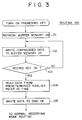
record key 16. Pushing the prerecord key 19 causes the disc recording and reproducing apparatus to enter a routine 100 shown in Fig. 3. Initially, thebuffer memory 35 is refreshed (step 101). The compressed audio data from the audio compression encoder-decoder circuit 33 is then written to thebuffer memory 35 successively (step 102). - In the above setup, the
buffer memory 35 provides a preceding data write area excluding an idle area and some memory areas reserved for other data. With respect to the preceding data write area, thebuffer memory 35 acts as one of the so-called ring buffers. Fig. 4A schematically shows how data is written on and read from thebuffer memory 35 in prerecording mode. Figs. 4A through 4C illustrate a ring-shaped memory area of thebuffer memory 35. - Pushing the prerecord key 19 starts the writing of compressed audio data to the
buffer memory 35, as depicted in Fig. 4A. In Figs. 4A through 4C, the shaded portions represent a memory area where data has been written. After the consecutive writing of compressed audio data to thebuffer memory 35 has filled its preceding data write area with the written data, new data is overwritten onto the oldest data and onward, as illustrated in Fig. 4B. - In this manner, the
buffer memory 35 is always filled with the compressed audio data in effect from a given preceding point in time up to the present time. The writing of compressed audio data to the preceding data write area of thebuffer memory 35 acting as a ring buffer continues until therecord key 16 is pushed. Eventually pushing therecord key 16 causes the preceding data to be recorded onto the optical disc 1B before normal recording mode is entered. - What takes place here is as follows: the operation of the
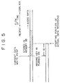
record key 16 is detected instep 103 of the routine 100 in Fig. 3. Step 103 is followed bystep 104. Instep 104, the data in thebuffer memory 35 is read therefrom starting from a point in time earlier by tb- minutes than the present time, the tb-minute prerecording time being preset on the variable input part 50 (Figs. 4C and 5). Because the data read from thebuffer memory 35 is compressed in the above setup, it is faster to read the data from thebuffer 35 than to compress the input audio data and write it to thememory 35. As a result, the compressed data continues to be written to thebuffer memory 35 even as data is being read therefrom. Under control of thememory controller 34, data is read from thebuffer memory 35 at a high speed in units of clusters until the quantity of data therein reaches the predetermined level, as described. - Step 104 is followed by
step 105 in which a plurality of clusters of data are recorded onto the optical disc 1B in a relatively short time. Because it takes about 0.4 seconds to record one cluster of data onto the disc, four to five clusters of data may be recorded in about 2 seconds. Thereafter, the normal recording routine takes over. - As described, the
buffer memory 35 is used as a ring buffer that can always retain up to its capacity the compressed audio data going back to an earlier point in time than the present time when therecord key 16 is pushed. The arrangement allows the data of the preceding period to be recorded before normal recording. This eliminates the possibility of failing to record the initial part of a sound sequence that is desired to be recorded. For example, a listener of radio broadcast may want to verify the contents of the program to be recorded off the radio before actually operating the record key. Pushing the record key after verification of the target program still allows the entire program to be recorded intact. This feature is particularly convenient when it permits a desired prerecording time to be set on the apparatus. - In the disc recording and reproducing apparatus of Fig. 1, the
buffer memory 35 is originally provided to compensate for the period of time in which to correct the pickup position dislodged as a result of vibration or other disturbance during recording or reproduction. Because the existingbuffer memory 35 may be utilized for the novel feature, there is no need to furnish a separate memory in which to store the data going back to an earlier point in time than the present time when the record key is pushed. - With the above-described embodiment, the
prerecord key 19 is operated to determine the preceding point in time at which to start storing data into thebuffer memory 35 before the record key is pushed for normal recording. Alternatively, the writing of data to thebuffer memory 35 may be started the moment the power switch 11 is turned on. In that case, there is no need to install theprerecord key 19. When normal recording mode is to be selected, theslide rheostat 50 need only be set for a prerecording time of 0 second. - With the disc recording and reproducing apparatus embodied as described, the variable input part on which to set the prerecording time is a slide rheostat. Alternatively, the slide rheostat may be replaced by a rotary rheostat. Another alternative is to replace the rheostat with a plurality of numeric keys constituting the variable input part. These numeric keys are used to enter a value into the system controller which sets the prerecording time accordingly. The prerecording time may be established using any appropriate means other than the slide rheostat or numeric keys.
Claims (10)
- A disc recording apparatus comprising:characterised in that:an encoder (33) for subjecting an input digital signal to data compression;a memory (35) for temporarily storing compressed data output from said encoder and having a storage capacity large enough to accommodate an amount of compressed data corresponding to a period of time from when a track jump occurs until the recording position is corrected;a head device (3) for recording onto a disc the data read from said memory; anda controller (20, 34) operative to control reading and writing of data to and from said memory, wherein the speed at which data is read from said memory for recordal is higher than the speed at which data is written to the memory from said encoder, and, during normal recording of data onto said disc, the points in the memory at which data is read and written are controlled such that: compressed data is written to the memory and when the quantity of data stored in the memory exceeds a predetermined level data is read from the memory for recordal; and, when it is detected that a track jump has occurred, compressed data is continuously written into the memory and data reading from the memory ceases, without cessation of writing of compressed data into the memory, until the recording position is corrected at which point data reading from the memory resumes,before said head device starts recording data onto said disc, compressed data from said encoder is continuously written to said memory without data being read from said memory, the point to which data is written being controlled such that the memory stores data of an input digital signal which is input over a period of time corresponding to the storage capacity of said memory; andwhen said head device starts recording data onto said disc in response to an input recording start instruction, data is read from said memory starting from the point in the memory at which is stored the compressed data of an input digital signal from an earlier point in time chronologically preceding the point in time at which said recording start instruction is input and the data is read at said higher speed until the quantity of data stored in said memory is reduced to said predetermined level whereupon said normal recording of data is carried out.
- A disc recording apparatus according to claim 1, wherein said controller is operative to erase the data stored temporarily in said memory prior to starting the recording of data onto said disc.
- A disc recording apparatus according to claim 1 or 2, wherein said memory is a random access memory.
- A disc recording apparatus according to claim 1, 2 or 3, further comprising:a first input part for setting a normal recording mode in which said head device records compressed data of an input digital signal from said point in time at which said recording start instruction is input; anda second input part for setting a prerecording mode in which said head device records compressed data of an input digital signal from said earlier point in time chronologically preceding the point in time at which said recording start instruction is input,wherein said first and said second input parts are connected to said controller.
- A disc recording apparatus according to claim 4, wherein said second input part comprises variable input means for setting as a variable amount the amount by which said earlier point in time chronologically precedes the point in time at which said recording start instruction is input.
- A disc recording apparatus according to claim 4 or 5, wherein said variable input means is a slide rheostat or potentiometer.
- A disc recording apparatus according to claim 4, 5 or 6, wherein:said apparatus further comprises a second encoder (36,37) for converting the compressed data read from said memory into record data;said controller comprises a memory controller (34) operative to control the writing and reading of data to and from said memory and a system controller (20) operative to controlling said head device, said second encoder and said memory controller;said system controller is operative in controlling the writing of data to said memory, to send a control signal to said memory controller in response to an input signal from said second input part so as first to erase the data in said memory before continuously writing thereto the data output from said first encoder.
- A disc recording method comprising the steps of:characterised by further comprising the steps of:subjecting an input digital signal to data compression;temporarily storing the compressed data in a memory having a storage capacity large enough to accommodate an amount of an amount of compressed data corresponding to a period of time from when a track jump occurs until the recording position is corrected;recording the data read from said memory onto a disc in a predetermined recording units; andduring normal recording of data onto said disc, controlling the points in the memory at which data is read and written such that: compressed data is written to the memory and, when the quantity of data stored in the memory exceeds a predetermined level, data is read from the memory for recordal at a speed higher than the speed at which data is written to the memory from said encoder; and, when it is detected that a track jump has occurred, compressed data is continuously written into the memory and data reading from the memory, without cessation of writing of compressed data into the memory, until the recording position is corrected at which point data reading from the memory resumes,when a prerecording mode is established and before said head device starts recording data onto said disc, continuously writing compressed data from said encoder to said memory without reading data from said memory, the point to which data is written being controlled such that the memory stores data of an input digital signal which is input over a period of time corresponding to the storage capacity of said memory; andwhen said head device starts recording data onto said disc in response to an input recording start instruction, reading data from said memory starting from the point in the memory at which is stored the compressed data of an input digital signal from an earlier point in time chronologically preceding the point in time at which said recording start instruction is input, at said higher speed until quantity of data stored in said memory is reduced to said predetermined level and then carrying out said normal recording of data.
- A disc recording method according to claim 8, wherein said predetermined amount is variably set by variable input means.
- A disc recording method according to claim 8 or 9, wherein said method further comprises, when said prerecording mode is established, erasing the data in said memory before continuously writing data to said memory.
Applications Claiming Priority (2)
| Application Number | Priority Date | Filing Date | Title |
|---|---|---|---|
| JP352064/92 | 1992-12-09 | ||
| JP35206492 | 1992-12-09 |
Publications (3)
| Publication Number | Publication Date |
|---|---|
| EP0601814A2 EP0601814A2 (en) | 1994-06-15 |
| EP0601814A3 EP0601814A3 (en) | 1995-10-18 |
| EP0601814B1 true EP0601814B1 (en) | 1999-05-06 |
Family
ID=18421540
Family Applications (1)
| Application Number | Title | Priority Date | Filing Date |
|---|---|---|---|
| EP93309741A Expired - Lifetime EP0601814B1 (en) | 1992-12-09 | 1993-12-06 | Disc recording and/or reproducing apparatus having a buffer memory |
Country Status (4)
| Country | Link |
|---|---|
| US (1) | US5418762A (en) |
| EP (1) | EP0601814B1 (en) |
| JP (1) | JP2001052437A (en) |
| DE (1) | DE69324775T2 (en) |
Cited By (1)
| Publication number | Priority date | Publication date | Assignee | Title |
|---|---|---|---|---|
| KR100369786B1 (en) * | 1995-01-25 | 2003-04-10 | 소니 가부시끼 가이샤 | Reproducing apparatus and control method of the apparatus |
Families Citing this family (39)
| Publication number | Priority date | Publication date | Assignee | Title |
|---|---|---|---|---|
| DK0465053T3 (en) * | 1990-06-29 | 2002-10-07 | Sony Corp | Plate recording / reproduction apparatus |
| US5677899A (en) | 1991-02-15 | 1997-10-14 | Discovision Associates | Method for moving carriage assembly from initial position to target position relative to storage medium |
| US6236625B1 (en) | 1991-02-15 | 2001-05-22 | Discovision Associates | Optical disc system having current monitoring circuit with controller for laser driver and method for operating same |
| US5729511A (en) | 1991-02-15 | 1998-03-17 | Discovision Associates | Optical disc system having servo motor and servo error detection assembly operated relative to monitored quad sum signal |
| JP3230319B2 (en) * | 1992-07-09 | 2001-11-19 | ソニー株式会社 | Sound reproduction device |
| KR950001695A (en) * | 1993-06-18 | 1995-01-03 | 오오가 노리오 | Disc player |
| JP3321950B2 (en) * | 1993-12-22 | 2002-09-09 | ソニー株式会社 | Disc player and method for processing reproduced data |
| JP2760287B2 (en) * | 1994-07-01 | 1998-05-28 | ヤマハ株式会社 | Disk recording and playback device |
| JP3560074B2 (en) * | 1994-07-29 | 2004-09-02 | ソニー株式会社 | Recording / reproducing device and memory control device |
| US6434087B1 (en) | 1995-01-25 | 2002-08-13 | Discovision Associates | Optical disc system and method for controlling bias coil and light source to process information on a storage medium |
| JP3720412B2 (en) * | 1995-05-01 | 2005-11-30 | キヤノン株式会社 | Information processing method and apparatus |
| JP3557721B2 (en) * | 1995-05-11 | 2004-08-25 | ソニー株式会社 | Recording device |
| KR100434410B1 (en) * | 1995-10-13 | 2005-05-24 | 소니 가부시끼 가이샤 | Optical disc player and optical disc playback method |
| TW332961B (en) * | 1996-02-09 | 1998-06-01 | Sony Co Ltd | Recording media |
| JP3363712B2 (en) | 1996-08-06 | 2003-01-08 | 株式会社リコー | Optical disk drive |
| JPH1055656A (en) * | 1996-08-08 | 1998-02-24 | Sony Corp | Received information recording system |
| JPH1064244A (en) * | 1996-08-23 | 1998-03-06 | Sony Corp | Storage medium and reproducing device |
| GB2326969B (en) * | 1997-07-02 | 2001-08-29 | Sanyo Electric Co | Disk playback device and method of terminating playback of disk |
| CA2769736C (en) * | 1997-07-09 | 2013-05-14 | Advanced Audio Devices, Llc | Device for editing and non-volatile optical storage of digital audio |
| US6587404B1 (en) * | 1997-07-09 | 2003-07-01 | Advanced Audio Devices, Llc | Optical storage device capable of recording a set of sound tracks on a compact disc |
| US20050169121A1 (en) * | 1997-07-09 | 2005-08-04 | Keller Peter J. | Optical storage device |
| JPH11143500A (en) * | 1997-11-05 | 1999-05-28 | Sony Corp | Ic recording and reproducing machine |
| US6320833B1 (en) * | 1998-05-07 | 2001-11-20 | Sony Corporation | Recording apparatus and method, and reproducing apparatus and method |
| JP2001283439A (en) * | 2000-03-31 | 2001-10-12 | Sanyo Electric Co Ltd | Method for setting light emitting output of optical head in optical disk recorder |
| JP2002112268A (en) * | 2000-09-29 | 2002-04-12 | Toshiba Corp | Compressed image data decoding apparatus |
| US20030214908A1 (en) * | 2002-03-19 | 2003-11-20 | Anurag Kumar | Methods and apparatus for quality of service control for TCP aggregates at a bottleneck link in the internet |
| DE10225624A1 (en) * | 2002-06-07 | 2003-12-18 | Bosch Gmbh Robert | Method for recording received information, in particular audio signals, by radio, in particular radio |
| KR20040028469A (en) * | 2002-09-30 | 2004-04-03 | 엘지전자 주식회사 | Method for managing a defect area on optical disc write once |
| US7233550B2 (en) * | 2002-09-30 | 2007-06-19 | Lg Electronics Inc. | Write-once optical disc, and method and apparatus for recording management information on write-once optical disc |
| ATE462184T1 (en) * | 2002-12-11 | 2010-04-15 | Lg Electronics Inc | OVERWRITE METHOD AND INFORMATION RECORDING METHOD FOR A WRITE-ONCE OPTICAL DISK |
| US7355934B2 (en) * | 2003-01-27 | 2008-04-08 | Lg Electronics Inc. | Optical disc of write once type, method, and apparatus for managing defect information on the optical disc |
| JP2004328545A (en) * | 2003-04-25 | 2004-11-18 | Sharp Corp | Decoding circuit, light-receiving amplifier circuit and optical pickup of disc recording/reproducing apparatus using the decoding circuit |
| EP2068322A3 (en) * | 2003-05-09 | 2009-09-23 | LG Electronics Inc. | Write once optical disc, and method and apparatus for recovering disc management information from the write once optical disc |
| KR100860985B1 (en) * | 2003-05-23 | 2008-09-30 | 삼성전자주식회사 | Method for recording/reproducing data on a disc using padding information |
| US7313065B2 (en) * | 2003-08-05 | 2007-12-25 | Lg Electronics Inc. | Write-once optical disc, and method and apparatus for recording/reproducing management information on/from optical disc |
| TWI245191B (en) * | 2004-09-14 | 2005-12-11 | Ali Corp | Sound receiving and pre-recording device and method |
| US20080175137A1 (en) * | 2007-01-23 | 2008-07-24 | Mediatek Inc. | Method for encoding data written to optical storage media |
| JP5538918B2 (en) * | 2010-01-19 | 2014-07-02 | キヤノン株式会社 | Audio signal processing apparatus and audio signal processing system |
| US20240153530A1 (en) * | 2022-11-07 | 2024-05-09 | Getac Technology Corporation | Voice activity detection device and method |
Citations (2)
| Publication number | Priority date | Publication date | Assignee | Title |
|---|---|---|---|---|
| JPS63282961A (en) * | 1987-05-14 | 1988-11-18 | Sony Corp | Adding device for tape recorder |
| JPH04348400A (en) * | 1991-05-10 | 1992-12-03 | Casio Comput Co Ltd | Voice recording device |
Family Cites Families (13)
| Publication number | Priority date | Publication date | Assignee | Title |
|---|---|---|---|---|
| JPS5841453A (en) * | 1981-09-01 | 1983-03-10 | Oki Electric Ind Co Ltd | Recording control circuit |
| JPS60195753A (en) * | 1984-03-16 | 1985-10-04 | Sony Corp | Sound-driven tape recorder |
| DE3528643A1 (en) * | 1985-08-09 | 1987-02-12 | Thomson Brandt Gmbh | TELEVISION RECEIVER |
| JP2995822B2 (en) * | 1990-08-23 | 1999-12-27 | ソニー株式会社 | Recording device and reproducing device for disk-shaped recording medium |
| JP3141242B2 (en) * | 1990-08-24 | 2001-03-05 | ソニー株式会社 | Optical disk recording device |
| US5126982A (en) * | 1990-09-10 | 1992-06-30 | Aaron Yifrach | Radio receiver and buffer system therefore |
| JP3036886B2 (en) * | 1991-05-29 | 2000-04-24 | 三洋電機株式会社 | Intermittent recording device for compressed audio data |
| JP3158556B2 (en) * | 1991-09-27 | 2001-04-23 | ソニー株式会社 | Disk recording device and disk reproducing device |
| JP3350976B2 (en) * | 1991-11-25 | 2002-11-25 | ソニー株式会社 | Disc playback device and recording device |
| JPH05242478A (en) * | 1992-03-02 | 1993-09-21 | Victor Co Of Japan Ltd | Recording and reproducing device |
| JP3435703B2 (en) * | 1992-05-20 | 2003-08-11 | ソニー株式会社 | Playback device and playback method |
| JP3355649B2 (en) * | 1992-05-20 | 2002-12-09 | ソニー株式会社 | Recording or playback device |
| JPH06259883A (en) * | 1993-03-05 | 1994-09-16 | Hitachi Ltd | Digital recording device for animation and sound, and method therefor |
-
1993
- 1993-12-03 US US08/161,241 patent/US5418762A/en not_active Expired - Lifetime
- 1993-12-06 DE DE69324775T patent/DE69324775T2/en not_active Expired - Fee Related
- 1993-12-06 EP EP93309741A patent/EP0601814B1/en not_active Expired - Lifetime
-
2000
- 2000-07-18 JP JP2000216879A patent/JP2001052437A/en active Pending
Patent Citations (2)
| Publication number | Priority date | Publication date | Assignee | Title |
|---|---|---|---|---|
| JPS63282961A (en) * | 1987-05-14 | 1988-11-18 | Sony Corp | Adding device for tape recorder |
| JPH04348400A (en) * | 1991-05-10 | 1992-12-03 | Casio Comput Co Ltd | Voice recording device |
Cited By (1)
| Publication number | Priority date | Publication date | Assignee | Title |
|---|---|---|---|---|
| KR100369786B1 (en) * | 1995-01-25 | 2003-04-10 | 소니 가부시끼 가이샤 | Reproducing apparatus and control method of the apparatus |
Also Published As
| Publication number | Publication date |
|---|---|
| DE69324775D1 (en) | 1999-06-10 |
| US5418762A (en) | 1995-05-23 |
| EP0601814A2 (en) | 1994-06-15 |
| JP2001052437A (en) | 2001-02-23 |
| DE69324775T2 (en) | 1999-11-04 |
| EP0601814A3 (en) | 1995-10-18 |
Similar Documents
| Publication | Publication Date | Title |
|---|---|---|
| EP0601814B1 (en) | Disc recording and/or reproducing apparatus having a buffer memory | |
| EP0630004B1 (en) | Disc reproducing apparatus | |
| KR100195317B1 (en) | Data recording and reproducing method | |
| JP3199082B2 (en) | Audio data break position adjustment method and apparatus | |
| US5502701A (en) | Optical disc recording apparatus which controls re-recording after a disturbance as a function of the capacity of an input buffer memory | |
| KR100255345B1 (en) | Method of and apparatus for reproducing a recording medium | |
| EP0700039B1 (en) | Optical recording/reproducing device | |
| US5440529A (en) | Audio and general digital data recording and/or reproducing apparatus having two interface circuits | |
| US5553055A (en) | Disc playback method | |
| US5453967A (en) | Disc reproducing apparatus which stops recording in response to compressed data stored, in a record stop state, in a memory | |
| US5633841A (en) | Optical disc recording/reproducing apparatus having automatic protection of previously recorded data | |
| JP3360873B2 (en) | Disk recording apparatus and method | |
| JP3438729B2 (en) | Playback device control method | |
| EP0596139B1 (en) | Optical disk recorder/reproducer | |
| JPH0778960B2 (en) | Image storage | |
| JPH06231538A (en) | Disk recorder/reproducer | |
| JP3482961B2 (en) | Disc recording / playback method | |
| JPH08124279A (en) | Recording and/or reproducing equipment of disk-shaped recording medium | |
| JPH0765507A (en) | Disk type recording medium recording and/or reproducing apparatus | |
| JPH1116289A (en) | Recorder | |
| JPH0877682A (en) | Reproducing apparatus and recording apparatus | |
| JPH04313876A (en) | Information reproducing device | |
| JPH08124277A (en) | Recording equipment of magneto-optical disk | |
| JPH09320196A (en) | Disk recording device | |
| JP2001357614A (en) | Method and device for data recording, and method and device for data reproduction |
Legal Events
| Date | Code | Title | Description |
|---|---|---|---|
| PUAI | Public reference made under article 153(3) epc to a published international application that has entered the european phase |
Free format text: ORIGINAL CODE: 0009012 |
|
| AK | Designated contracting states |
Kind code of ref document: A2 Designated state(s): DE FR GB |
|
| K1C2 | Correction of patent application (partial reprint) published |
Effective date: 19940615 |
|
| PUAL | Search report despatched |
Free format text: ORIGINAL CODE: 0009013 |
|
| AK | Designated contracting states |
Kind code of ref document: A3 Designated state(s): DE FR GB |
|
| 17P | Request for examination filed |
Effective date: 19960321 |
|
| 17Q | First examination report despatched |
Effective date: 19970214 |
|
| GRAG | Despatch of communication of intention to grant |
Free format text: ORIGINAL CODE: EPIDOS AGRA |
|
| GRAG | Despatch of communication of intention to grant |
Free format text: ORIGINAL CODE: EPIDOS AGRA |
|
| GRAG | Despatch of communication of intention to grant |
Free format text: ORIGINAL CODE: EPIDOS AGRA |
|
| GRAH | Despatch of communication of intention to grant a patent |
Free format text: ORIGINAL CODE: EPIDOS IGRA |
|
| GRAH | Despatch of communication of intention to grant a patent |
Free format text: ORIGINAL CODE: EPIDOS IGRA |
|
| GRAA | (expected) grant |
Free format text: ORIGINAL CODE: 0009210 |
|
| AK | Designated contracting states |
Kind code of ref document: B1 Designated state(s): DE FR GB |
|
| REF | Corresponds to: |
Ref document number: 69324775 Country of ref document: DE Date of ref document: 19990610 |
|
| ET | Fr: translation filed | ||
| PLBE | No opposition filed within time limit |
Free format text: ORIGINAL CODE: 0009261 |
|
| STAA | Information on the status of an ep patent application or granted ep patent |
Free format text: STATUS: NO OPPOSITION FILED WITHIN TIME LIMIT |
|
| 26N | No opposition filed | ||
| REG | Reference to a national code |
Ref country code: GB Ref legal event code: IF02 |
|
| PGFP | Annual fee paid to national office [announced via postgrant information from national office to epo] |
Ref country code: FR Payment date: 20081212 Year of fee payment: 16 |
|
| PGFP | Annual fee paid to national office [announced via postgrant information from national office to epo] |
Ref country code: DE Payment date: 20081205 Year of fee payment: 16 |
|
| PGFP | Annual fee paid to national office [announced via postgrant information from national office to epo] |
Ref country code: GB Payment date: 20081203 Year of fee payment: 16 |
|
| GBPC | Gb: european patent ceased through non-payment of renewal fee |
Effective date: 20091206 |
|
| REG | Reference to a national code |
Ref country code: FR Ref legal event code: ST Effective date: 20100831 |
|
| PG25 | Lapsed in a contracting state [announced via postgrant information from national office to epo] |
Ref country code: FR Free format text: LAPSE BECAUSE OF NON-PAYMENT OF DUE FEES Effective date: 20091231 |
|
| PG25 | Lapsed in a contracting state [announced via postgrant information from national office to epo] |
Ref country code: DE Free format text: LAPSE BECAUSE OF NON-PAYMENT OF DUE FEES Effective date: 20100701 |
|
| PG25 | Lapsed in a contracting state [announced via postgrant information from national office to epo] |
Ref country code: GB Free format text: LAPSE BECAUSE OF NON-PAYMENT OF DUE FEES Effective date: 20091206 |