EP0601811B1 - Measurement-while-drilling system using mud-pulse valve for data transmission - Google Patents
Measurement-while-drilling system using mud-pulse valve for data transmission Download PDFInfo
- Publication number
- EP0601811B1 EP0601811B1 EP93309731A EP93309731A EP0601811B1 EP 0601811 B1 EP0601811 B1 EP 0601811B1 EP 93309731 A EP93309731 A EP 93309731A EP 93309731 A EP93309731 A EP 93309731A EP 0601811 B1 EP0601811 B1 EP 0601811B1
- Authority
- EP
- European Patent Office
- Prior art keywords
- mud
- sonde
- passage
- flow
- straight
- Prior art date
- Legal status (The legal status is an assumption and is not a legal conclusion. Google has not performed a legal analysis and makes no representation as to the accuracy of the status listed.)
- Expired - Lifetime
Links
- 238000005553 drilling Methods 0.000 title claims description 11
- 230000005540 biological transmission Effects 0.000 title 1
- 230000000694 effects Effects 0.000 claims description 10
- 230000007246 mechanism Effects 0.000 claims description 9
- UIIMBOGNXHQVGW-UHFFFAOYSA-M Sodium bicarbonate Chemical compound [Na+].OC([O-])=O UIIMBOGNXHQVGW-UHFFFAOYSA-M 0.000 claims description 4
- 239000002253 acid Substances 0.000 claims description 3
- 238000006243 chemical reaction Methods 0.000 claims description 3
- 238000005259 measurement Methods 0.000 claims description 3
- 238000007664 blowing Methods 0.000 claims description 2
- 229910000030 sodium bicarbonate Inorganic materials 0.000 claims description 2
- 235000017557 sodium bicarbonate Nutrition 0.000 claims description 2
- 238000012545 processing Methods 0.000 description 21
- 239000007789 gas Substances 0.000 description 11
- 238000000034 method Methods 0.000 description 6
- 230000008569 process Effects 0.000 description 6
- 238000011144 upstream manufacturing Methods 0.000 description 5
- 230000008859 change Effects 0.000 description 4
- 238000005520 cutting process Methods 0.000 description 3
- 239000000203 mixture Substances 0.000 description 3
- 238000012544 monitoring process Methods 0.000 description 3
- 230000002159 abnormal effect Effects 0.000 description 2
- 238000010586 diagram Methods 0.000 description 2
- 230000004048 modification Effects 0.000 description 2
- 238000012986 modification Methods 0.000 description 2
- 229910000831 Steel Inorganic materials 0.000 description 1
- 238000006757 chemical reactions by type Methods 0.000 description 1
- 239000004020 conductor Substances 0.000 description 1
- CEALXSHFPPCRNM-UHFFFAOYSA-L disodium;carboxylato carbonate Chemical compound [Na+].[Na+].[O-]C(=O)OC([O-])=O CEALXSHFPPCRNM-UHFFFAOYSA-L 0.000 description 1
- -1 geothermal Substances 0.000 description 1
- 238000005339 levitation Methods 0.000 description 1
- 239000000463 material Substances 0.000 description 1
- 239000002343 natural gas well Substances 0.000 description 1
- 239000002245 particle Substances 0.000 description 1
- 239000003208 petroleum Substances 0.000 description 1
- 239000011435 rock Substances 0.000 description 1
- 239000013049 sediment Substances 0.000 description 1
- 230000035939 shock Effects 0.000 description 1
- 239000010959 steel Substances 0.000 description 1
- 239000004575 stone Substances 0.000 description 1
- 239000002699 waste material Substances 0.000 description 1
- XLYOFNOQVPJJNP-UHFFFAOYSA-N water Substances O XLYOFNOQVPJJNP-UHFFFAOYSA-N 0.000 description 1
Images


Classifications
-
- E—FIXED CONSTRUCTIONS
- E21—EARTH OR ROCK DRILLING; MINING
- E21B—EARTH OR ROCK DRILLING; OBTAINING OIL, GAS, WATER, SOLUBLE OR MELTABLE MATERIALS OR A SLURRY OF MINERALS FROM WELLS
- E21B23/00—Apparatus for displacing, setting, locking, releasing or removing tools, packers or the like in boreholes or wells
-
- E—FIXED CONSTRUCTIONS
- E21—EARTH OR ROCK DRILLING; MINING
- E21B—EARTH OR ROCK DRILLING; OBTAINING OIL, GAS, WATER, SOLUBLE OR MELTABLE MATERIALS OR A SLURRY OF MINERALS FROM WELLS
- E21B41/00—Equipment or details not covered by groups E21B15/00 - E21B40/00
- E21B41/0085—Adaptations of electric power generating means for use in boreholes
-
- E—FIXED CONSTRUCTIONS
- E21—EARTH OR ROCK DRILLING; MINING
- E21B—EARTH OR ROCK DRILLING; OBTAINING OIL, GAS, WATER, SOLUBLE OR MELTABLE MATERIALS OR A SLURRY OF MINERALS FROM WELLS
- E21B47/00—Survey of boreholes or wells
- E21B47/01—Devices for supporting measuring instruments on drill bits, pipes, rods or wirelines; Protecting measuring instruments in boreholes against heat, shock, pressure or the like
-
- E—FIXED CONSTRUCTIONS
- E21—EARTH OR ROCK DRILLING; MINING
- E21B—EARTH OR ROCK DRILLING; OBTAINING OIL, GAS, WATER, SOLUBLE OR MELTABLE MATERIALS OR A SLURRY OF MINERALS FROM WELLS
- E21B47/00—Survey of boreholes or wells
- E21B47/12—Means for transmitting measuring-signals or control signals from the well to the surface, or from the surface to the well, e.g. for logging while drilling
- E21B47/13—Means for transmitting measuring-signals or control signals from the well to the surface, or from the surface to the well, e.g. for logging while drilling by electromagnetic energy, e.g. radio frequency
-
- E—FIXED CONSTRUCTIONS
- E21—EARTH OR ROCK DRILLING; MINING
- E21B—EARTH OR ROCK DRILLING; OBTAINING OIL, GAS, WATER, SOLUBLE OR MELTABLE MATERIALS OR A SLURRY OF MINERALS FROM WELLS
- E21B47/00—Survey of boreholes or wells
- E21B47/12—Means for transmitting measuring-signals or control signals from the well to the surface, or from the surface to the well, e.g. for logging while drilling
- E21B47/14—Means for transmitting measuring-signals or control signals from the well to the surface, or from the surface to the well, e.g. for logging while drilling using acoustic waves
- E21B47/18—Means for transmitting measuring-signals or control signals from the well to the surface, or from the surface to the well, e.g. for logging while drilling using acoustic waves through the well fluid, e.g. mud pressure pulse telemetry
- E21B47/20—Means for transmitting measuring-signals or control signals from the well to the surface, or from the surface to the well, e.g. for logging while drilling using acoustic waves through the well fluid, e.g. mud pressure pulse telemetry by modulation of mud waves, e.g. by continuous modulation
-
- E—FIXED CONSTRUCTIONS
- E21—EARTH OR ROCK DRILLING; MINING
- E21B—EARTH OR ROCK DRILLING; OBTAINING OIL, GAS, WATER, SOLUBLE OR MELTABLE MATERIALS OR A SLURRY OF MINERALS FROM WELLS
- E21B47/00—Survey of boreholes or wells
- E21B47/12—Means for transmitting measuring-signals or control signals from the well to the surface, or from the surface to the well, e.g. for logging while drilling
- E21B47/14—Means for transmitting measuring-signals or control signals from the well to the surface, or from the surface to the well, e.g. for logging while drilling using acoustic waves
- E21B47/18—Means for transmitting measuring-signals or control signals from the well to the surface, or from the surface to the well, e.g. for logging while drilling using acoustic waves through the well fluid, e.g. mud pressure pulse telemetry
- E21B47/24—Means for transmitting measuring-signals or control signals from the well to the surface, or from the surface to the well, e.g. for logging while drilling using acoustic waves through the well fluid, e.g. mud pressure pulse telemetry by positive mud pulses using a flow restricting valve within the drill pipe
Definitions
- This invention is broadly concerned with a measuring tool for collecting down hole information and intended particularly to be used to collect data down hole in a vertical/inclined borehole for petroleum, geothermal, or natural gas wells, or for seismic observation or geological survey.
- boreholes are generally drilled by rotation of a long and narrow drill string having a drill bit at its lower end.
- the drill string is adapted so that mud can flow thereinside.
- the mud-flow is transferred through the drill string from the surface down the borehole and is then returned to the surface through the annular space between the drill string and the wall of the borehole.
- This circulation of the mud flow entrains the drill cuttings such as stones, rocks and sediment, and brings them to the surface.
- the mud-flow down the borehole generally has a high temperature because of geothermal heat and water pressure.
- the permanent-type down hole information collecting device is so arranged that sensors and a main part thereof are associated into a bitsub as an auxiliary pipe to connect the drill bit with the drill string.
- the retrievable-type down hole information collecting device comprises a sonde containing therein the sensors integral with the main part. This sonde is provided with the bitsub separately so that it can be withdrawn to the surface on a wire line.
- the retrievable-type down hole information collecting device will not be damaged by extreme heat, pressure and the like, since the sonde can be withdrawn from down hole to the ground level.
- electrical connections between the sonde and the sensors installed in the drill bit are not sufficient to allow information around the drill to be collected reliably.
- the down hole information collecting device is generally provided with a mud-pulse generating device to transmit down hole information to ground level.
- the mud-pulse generating device sends information to the surface by means of pressurized pulses which propagate through the mud in the drill string.
- the above-mentioned device employs a metering valve which can quickly change the flow rate of the mud-flow so as to generate the pressurized pulses.
- One known metering valve employs a mechanical type switching valve where a port passing through the mud-flow is opened and shut repeatedly using a plug.
- a relatively large port and corresponding plug are necessary to maintain sufficient mud, which naturally causes difficulty transmitting the pressurized pulse, and a waste of electrical power when operating the metering valve, because of the heavy weight of the plug and the resistance caused by the mud-flow.
- the slight gap immediately before and after a complete closing of the associated port may cause high speed flow of the mud to wear the surfaces of the associated members. Furthermore, the presence of drill cuttings in the mud-flow between the port and the plug may cause severe problems of unforeseen shock and vibration of the drill bit.
- the present invention aims to provide a measuring tool which can collect information near the drill bit in a vertical/inclined borehole and which is so arranged that a main part thereof can be retrieved to the surface if necessary.
- EP 0539246 which is prior art under Article 54(3) EPC only, discloses a measurement while drilling system in which a critical signal is sent to the surface, and a signal to retrieve a sonde is sent back down the borehole.
- a measurement while drilling system for collecting down hole information in a borehole, the system comprising: a sensor sub having, at a lower portion of a drill string, sensors to collect data; a sonde for actively transmitting the information to the surface, the sonde being movable in an upper and lower direction in the drill string; a signal sending portion at the sensor sub; a signal receiving portion, at the sonde; a radiocommunication means to effect radiocommunication by means of an electromagnetic wave through the signal sending portion and the signal receiving portion; and a floating device for raising the sonde by means of buoyancy of a chamber in which a gas is chemically generated in a gas generator.
- the signal sending and receiving portions preferably consist of loop antennas.
- the chemical reaction in the gas generator is preferably effected by sodium bicarbonate and an acid.
- the sonde may include a criticalness detecting means which compares a prepared standard value with a measured value of the sensors in the sensor sub and issues a signal when, the measured value is beyond the standard value.
- the sonde is preferably integrated with a centraliser, so that the central axis of the sonde is axially aligned with the central axis of the drilling pipe.
- the centraliser consists of plural arch-shaped blade springs extending in the axial direction of the sonde.
- the system may be provided with a metering valve for producing a mud-pulse in a mud-flow, the valve comprising a straight passage for a straight stream of the mud-flow; a detour passage providing a tortuous path for the mud flow; and a changeover means for shifting a main stream of the mud-flow between the straight passage and the detour passage.
- the changeover means is reciprocally projectable from and retractable into a branch portion of the straight passage and the detour passage.
- the changeover means may be an inclination rod.
- the changeover means may be capable of rotating round an axis parallel to a central axis of the straight passage and may have a straight hole axially aligned with the straight passage and a backflow path branched from the straight hole.
- the changeover means can be installed in a wall of the sonde.
- the changeover means may consist of an orifice blowing the mud-flow, a pair of control ports confronting each other behind the orifice, conduit pipes respectively connected with the control ports and valves provided on the respective conduit pipes.
- the changeover means consists of rod springs to which elements of the changeover means are attached and a partially tapered shaft which is movable forwards and backwards reciprocally by the rod springs, so that each element of the changeover means is correspondingly projected and retracted.
- the changeover means may consist of a changeover element, an arm which is integrated with and swings the changeover element, a driving shaft, a cam mechanism to convert a rotation of the driving shaft to a swing of the arm and a driving means to rotate the driving shaft.
- the changeover element of the changeover means may be moved by a driving mechanism which has a solenoid.
- the detour passage preferably has a swirl generating device.
- the detour passage may be formed by spiral grooves.
- the detour passage may have at least one vane. There may be a plurality of vanes which overlap one another and are arranged helically between the respective edges of the spiral grooves.
- the detour passage may have a straight introductory path.
- Figure 1 shows a drilling tool 10 according to the first embodiment which comprises a drill string 12 consisting of steel pipes 11 connected end to end.
- the drill string 12 has at its lower end a drill bit 13.
- a measuring tool 2 for collecting down hole information is provided at the lower part of the drill string 12.
- a mud pump 15 and a data processing system 16 are located around a drill rig 14.
- the data processing system 16 is preferably a computer capable of indicating data every moment collected by the measuring tool 2 and also successively analysing the collected data.
- This data processing system 16 also includes sensors (not shown), by which a mud-pulse as a pressure wave originally sent from the measuring tool 2 and transmitted through the mud can be received.
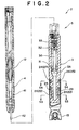
- Figure 2 shows the measuring tool 2 in an enlarged state.
- the measuring tool 2 is defined by a sensorsub 3 which is oriented between the drill bit 13 and the drill string 12 and a sonde 4 which can be moved smoothly in the drill string 12 to provide a retrievable system.
- the sensorsub 3 is generally formed into a cylindrical shape with a thick wall 3A. Inside the thick wall 3A of the sensorsub 3 and near the drilling bit 13, bit load sensors 21 and bit torque sensors 22 along with respective amplifiers 23 are preferably arranged as shown in Figure 3.
- the bit load sensors 21 and the bit torque sensors 22 are alternately disposed at intervals of 90 degrees on a circle round a central axis of the sensorsub 3.
- the wall 3A also contains, at an upper part of the amplifiers 23 in Figure 2, an internal temperature sensor 24 to measure the inside temperature of the sensorsub 3, an external temperature sensor 25 to measure the temperature in the borehole 1, an external pressure sensor 26 to sense a pressure in the borehole 1 and a processing unit 27 to digitize data obtained in the sensors 24, 25, 26.
- the sensorsub 3 also has therein a generator 30 having a column shape. It will be seen in Figure 2 that the generator 30 has a turbine 31 at its lower end, which is rotated in the mud-flow flow to generate the necessary electrical power.
- the generator 30 is also provided, at its upper end, with another turbine 32 capable of being rotated freely by the mudflow.
- This turbine 32 has at top portion thereof a hole 33 with keying ribs.
- the sonde 4 is formed as long and narrow rod.
- the sonde 4 has at its lower portion, as depicted in Figure 2, a generator 41 of its own, which is independent of the generator 30 provided in the sensorsub 3.
- the generator 41 is provided with a rotatable propeller shaft 42 extending to the turbine 32.
- a key which engages the keying ribs in the hole 33 of the turbine 32, so that when engaged the mud-flow flow can effect a rotation of the turbine 32 thereby to generate sufficient electrical power in the generator 41.
- the loop antenna 51 is integrated with a baffle plate 34 across the circular wall 3A of the sensorsub 3.
- the baffle plate 34 has at its centre portion a hole 35 to receive therein the propeller shaft 42 of the sonde 4.
- the loop antenna 52 is attached to a lower end portion 43 of the sonde 4 near the sensorsub 3.
- the lower end portion 4 has a hole 44 to keep the propeller shaft 42 rotatable.
- both central axes of the loop antennas 51 and 52 will be axially aligned with each other, when the propeller shaft 42 of the sonde 4 is inserted into the hole 35 of the baffle plate 34.
- the loop antennas 51, 52 are made with a conductive material so that the data processed in the processing unit 27 is sent from the loop antenna 51 toward the sonde 4 and will be received at the loop antenna 52.
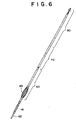
- Figure 6 is a front view indicating the overall composition of the sonde 4.
- the sonde 4 has an arch-shaped centraliser 45 bulging in the radial direction, an electronic device receiving portion 60 which process measured data, a floating device 70 to raise the sonde to ground level, and a mud pulse generating device 80 which changes the obtained data to pressure pulse and sends the pressure pulse to the surface through the mud in the drill string 12.
- the centraliser 45 has a plurality of arch-shaped blade springs so that the central axis of the sonde 4 can be axially aligned with that of the drill string 12.
- the propeller shaft 42 can be smoothly coupled into the turbine 32 in the sensorsub 3 by means of the mentioned centraliser 45.
- the electronic devices receiving portion 60 is a heat insulating closed housing which is adapted to receive therein electrical elements like a high-temperature IC so that operation of the electrical elements occurs in a high temperature and a high pressure mud-flow.
- the floating device 70 consists essentially of a gas generator 71 to produce a high pressure gas by a chemical reaction and a chamber 72 to store the gas from the gas generator 71, as shown in Figure 7.
- the gas generator 71 can chemically react materials like sodium dicarbonate and an acid in a case 3 and feed the pressurised gas chemically obtained into the chamber 72 via a pipe 74.
- the chamber 72 is a vacant space inside the sonde 4 and has at its lower end a discharge port 75 for the mud-flow.
- the chamber 72 When collecting data, the chamber 72 is filled up with mud so that the sonde 4 can be kept in the mud-flow. When it is necessary to take the sonde 4 out from the borehole 1, the gas produced in the gas generator 71 is fed into the chamber 72 whereby the sonde 4 can rise to the surface.
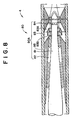
- the mud pulse generating device 80 comprises a metering valve 80A as shown in Figures 8 and 9.
- the metering valve 80A can be operated by a column-shaped driving device 81 which is installed in the sonde 4.
- a straight passage 82 as an opened path and a detour passage 83 as an interference passage between the driving device 81 and a housing 88 of the sonde 4.
- the housing 88 has an inlet (not shown) for an inflow of the mud from the outside and an outlet (not shown) for an outflow of the same from the passages 82 and 83 to the outside of the sonde 4.
- the driving device 81 has at the forward end a changeover element 84 of which each element is reciprocally movable and has a wedge shape, as can be seen in Figures 10 and 11.
- the straight passage 82 is formed into a straight shape not to cause flow resistance of the mud-flow.
- a sectional shape of the detour passage 83 is as shown in Figures 9 to 11.
- An inlet 83A and an outlet 83B of the detour passage 83 are opened towards the upstream side of the mud-flow.
- the radially reciprocal movement of the changeover element 84 by means of the driving device 81 can shift the main mud-flow stream from one of the straight passage 82 and the detour passage 83 to the other.
- the details of the driving device 81 are depicted in Figure 12, wherein a driving mechanism 85 for moving the above-explained changeover element 84 is illustrated.
- the driving mechanism 85 consists of a long rod-like spring 86 along the longitudinal direction of the driving device 81 and a shaft 87 movable along the same.
- the shaft 87 has a conic surface 87A at its forward portion and is provided with, at its backward portion, a driving means such as a solenoid or a motor so as to be movable in a longitudinal direction.
- a driving means such as a solenoid or a motor so as to be movable in a longitudinal direction.
- the spring 86 is adapted so that its one end portion 86A is secured to an inside wall of the driving device 81 and the other end 86B is related to the changeover element 84 to move reciprocally in the radial direction of the driving device 81.
- the changeover element 84 is permanently urged to the forward portion of the shaft 87 by the spring 86.
- an advance movement of the shaft 87 effects a reciprocal projection of the changeover element 84 because of the conic surface 87A, while a return movement of the same retracts the changeover element 84.
- the mechanism which causes reciprocal movement of the changeover element 84 by means of the shaft 87 is referred to as the driving mechanism 85.
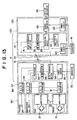
- Figure 13 shows an electric circuit 6 for the measuring tool 2 for collecting down hole information.
- the electric circuit 6 comprises a sensing processor 90 provided in the sensorsub 3 and a sending processor 100 provided in the sonde 4.
- the sensing processor 90 essentially includes the above mentioned sensors 21, 22, exclusive amplifiers 23 for each sensor and a processing unit 27 to change plural analog signals measured in the sensors 21, 22 into series digital signals.
- the processing unit 27 consists of A/D converters 91 to change analog signals measured by the sensors 21, 22 into digital signals, a processor 92 to regulate parallel digital signals sent from the A/D converters 91 to a series digital signal, a FM modulator 93 to modulate the series digital signal made in the processor 92, and a high-frequency driver 94 to generate carry waves for modulation.
- the FM modulator 93 and the high-frequency driver 94 are referred to as a radiocommunication means in the sensorsub 3.
- the processing unit 27 is adapted to send, from the antenna 51, the series digital signal measured by the sensors 21, 22 as a high-frequency signal.
- the processing unit 27 is equipped with a power circuit 95 to supply constantly DC voltage to the exclusive amplifiers 23 for the sensors 21, 22 and the like, the electric power in the power circuit 95 being supplied from the generator 30.
- the sending processor 100 comprises a signal processing unit 110 demodulating the high-frequency signal which is sent from the processing unit 27 and caught at the antenna 52 and a control unit 120 controlling the driving mechanism 85 of the mud pulse generating device 80 based on the signals issued from the signal processing unit 110.
- the signal processing unit 110 is defined by a nigh-frequency amplifier 111 amplifying the digital signals received at the antenna 52, a FM demodulator 112 to demodulate the digital signals, a processing device 113 to translate the demodulated digital signals to the operating speed of the mud pulse generating device 80, and a monitoring circuit 114 to watch the signals inputted to the processing device 113.
- the high-frequency amplifier 111 and the FM demodulator 112 are referred to as a radiocommunication means in the sonde 4.
- the control unit 120 has a signal converter 121 to convert weak signals sent from the processing device 113 to electric information for the mud pulse generating device 80, and a power circuit 122 to supply a necessary electric power to the signal converter 121.
- the monitoring circuit 114 of the signal processing unit 110 is a criticalness detecting means which determines whether the sonde 4 is safe or not.
- the monitoring circuit 114 has, as shown in Figure 14, an input portion 131 to receive digital signals from the processing device 113, a decision circuit 132 to determine whether the sonde 4 is in a critical condition or not based on the digital signals from the input portion 131, a command signal generating portion 133 to send prepared command signals, a selecting portion 134 to choose either output from the command signal generating portion 133 or from the input portion 131 based on a critical signal issued from the decision circuit 132, and an output portion 135 to return the output of the selecting portion 134 to the processing device 113.
- the decision circuit 132 consists of a memory portion 136 to memorize predetermined standard values, a storage portion 137 to temporarily keep digital signals from the input portion 131, and a comparison portion 138 to compare the digital signal from the storage portion 137 with the standard value in the memory portion 136.
- the comparison portion 138 can analyze a critical state of the sonde when at least one of the digital signals is beyond the predetermined standard value such as temperature, pressure, torque or the like, and thereby inform of the critical state of the sonde to the selecting portion 134. At this time, an under voltage of the generator 41 is also detected to confirm no flow of the mud whereat the floating device 70 can be operated.
- the selecting portion 134 outputs a command signal from the command signal generating device 133 to the output portion 135 after receiving the signal indicating a critical state of the sonde. This command is sent to the ground level from the mud pulse generating device 80 to inform the critical state of the sonde stops the feeding of the mud-flow.
- the signal processing unit 110 is also provided with a power circuit 115 to supply stable DC current to the high-frequency amplifier 111 and the FM demodulator 112.
- the power circuit 115 includes a secondary battery for memory backup of the memory portion 136. Incidentally, this power circuit 115 and the power circuit 122 provided for the control unit 120 can receive electric power from the generator 41.
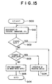
- the critical state of the sonde 4 can be prevented by steps shown in Figure 15 according to this embodiment.
- the measuring tool 2 begins to work at a step S100.
- necessary data such as temperature, pressure and so on are measured by the temperature sensor 25 and the pressure sensor 26.
- a step S102 it will be evaluated, in the decision circuit 132, whether the measured data accords with the predetermined standard value or not.
- step S101 When all of the measured data are deemed safe, the mentioned steps from the step S101 will be repeated continuously. However, if at least one of the measured data is out of the standard value, the process will advance to a step S103 to sense the mud-flow flow in the drilling pipe 12 by means of sensors connected with the data processing system 16.
- step S104 When the mud-flow flow is detected, the process further advances to a step S104 and send a command to the ground level to stop the supply of the mud-flow.
- the steps S103 to S104 will be repeated until the mud-flow flow comes to an end.
- the process will advance to a next step S105 to operate the floating device 70 whereat the sonde 4 can be prevented from reaching a critical state and the process shown in Figure 15 will further advance to a last step S106 to end the whole process.
- An abnormal vibration in the shaft 1 can be detected by the pressure sensor 26 and the bit torque sensor 22, so that the sonde can avoid problems due to the abnormal vibration.
- Necessary data at the drilling bit 13 can be transmitted reliably by employing the tool according to this embodiment, as the sensorsub 3 and the sonde 4 respectively have directional loop antennas 51, 52 along with the radiocommunication devices, which transmit reliably data from the sensorsub 3 to the sonde 4.
- the sensorsub 3 and the sonde 4 have the generators 30 and 41 respectively, each of which generates enough electric power by utilizing the mud-flow flow, whereby no electric supply to the tool 2 is necessary to collect continuously information in the borehole 1.
- the sonde 4 retrieved from the ground by means of the criticalness detecting means determining whether the sonde 4 is safe or not.
- the sonde 4 has the chemical reaction type floating device 70 which operates better than a mechanical device.
- the mud-flow smoothly flows inside the mud pulse generating device 80, and is used in the metering valve 80A which can vary a total resistance of the mud-flow flown in the detour passages 82, 83.
- the valve 80A can be operated with a small electric power, since the dimensions of the changeover element 84 are relatively small.
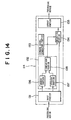
- FIG. 16 A second embodiment of another mud pulse generating device is shown in Figure 16. This embodiment employs a rotational-type driving device 181 instead of the reciprocal-type driving device 81 employed in the metering valve 80A of the first embodiment.
- the driving device 181 essentially consists of a pivotal arm 186 and an axle 187 with a circular cross section connected each other.
- the arm 186 is adapted to swing about an intermediated portion 186A where a projection from the inner surface of the driving device 181 is provided.
- the arm 186 has, at its right end portion in Figure 16, a changeover element 84 almost same as in the first embodiment and, at its left end portion, a cam-follower pin 188A extending along a rotation axle 187 which is directly connected with a driving source such as a motor.
- the rotation axle 187 is rotatably supported in a bearing 181A fixed to the driving device 181.
- the driving source for the rotation axle 187 can positively and negatively rotate through a certain rotation angle of the axle 187.
- a cam 188B relating to the cam-follower pin 188A of the arm 186.
- the cam 188B is provided with slots 189B in a rotatable plate 189A to receive respective cam-follower pins 188A.
- Each of the slots 189B for example from a portion denoted by 189C to that denoted by 189D, extends helically outwardly about a centre of the rotating plate 189A.
- the changeover element 84 can be reciprocally and radially moved relative to the driving device 181.
- This second embodiment can naturally achieve the advantages of the first embodiment.
- the changeover element 84 is reciprocally and forcibly moved by a combination with the cam-follower pin 188A and the corresponding cam 188B, inferior operation of the element 84 can be prevented.
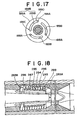
- Figure 18 shows the third embodiment of the metering valve.
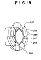
- This embodiment employs a tortuous passage 283 for causing swirl of the mud which replaces the detour passage 83 in the metering valve 80A of the first embodiment.
- the tortuous passage 283 has a cylindrical space in the sonde 4, which space is defined by a female spiral groove 286 on an outer side wall 284 of the sonde 4 and a male spiral groove 287 on an inner side wall 285.
- Vanes 288 are arranged at an inlet port 283A and an outlet port 283B of the tortuous passage 283.
- the vanes 288 are helical and overlap between the respective edges of the spiral grooves 286 and 287 as shown in Figure 19.
- This embodiment can also achieve the same operations and effects as in the first and second embodiments. Because of a combination with the pair of the spiral grooves 286, 287 and the vanes 288, the tortuous passage 283 can effect the swirl and cause a large resistance in the passage 283.
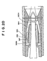
- Figure 20 shows the fourth embodiment of the metering valve.
- the metering valve in this embodiment employs another tortuous passage 283 which differs from that in the third embodiment in that there are no vanes in the tortuous passage 283.
- an inlet port 383A of the tortuous passage 383 is provided a straight introductory path 384.
- the diameter of the introductory path 384 is gradually spread in the flow direction of the flow, which is effective to cause swirl in the pair of spiral grooves 386, 387.
- This embodiment naturally provide the same advantages as in the first to third embodiments and is easier to produce than the third embodiment as it has no vanes.
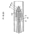
- Figure 21 shows the fifth embodiment of the metering valve.
- a rotatable changeover element 484 is employed in this embodiment in place of the changeover element 84 in the metering valve 80A of the first embodiments.
- Straight passages 482 in this embodiment are arranged around a driving device 481. To an inlet section of the passages 482 is attached the conic changeover element 484.
- the changeover element 484 is provided with holes 484A at intervals on a concentric circle so as to open and close the passages 482, being rotated by the shaft 487.
- the changeover element 484 also has a backflow path 483 near an opening 484B of the hole 484A.
- the respective paths 483 can effect a main stream of the mud-flow.
- the mud-flow advances into the passages 482 via the holes 484A and the backflow paths 483 with a low flow resistance to the mud-flow.
- the open passage 582 is straight to suppress flow resistance of the mud-flow.
- the interference passage 583 is a branch stream from the open passage 582. Both an inlet opening 583A and an outlet opening 583B of the interference passage 583 face upstream, so that the mud-flow fed in the opening 583A and out from the opening 583B so as to flow backwards to the stream.
- an inclination rod 584 is provided, in a reciprocal state, to effect the mudflow stream.
- the inclination rod 584 has at the forward end an inclined plane 584A to guide the mud-flow to the inlet opening 583A of the interference passage 583.
- the reciprocal movement of the inclination rod 584 is controlled by a solenoid valve 587 which is related with a root portion of the rod 584 and is received in the wall 88A.
- This embodiment provides the following advantages.
- a desirable amplitude of the pressure pulse wave to send data to the ground level can be obtained by a combination of two passages and the movement of the metering valve 80A.
- the inclination rod 584 does not need to close the passages to change the direction of the mud-flow whereat the scale and the movement degree of the rod 584 can be minimized. Hence, the inclination rod 584 can be moved rapidly to produce highly efficient pressure pulses by means of the solenoid valve 587 with rather low electric power.
- the projected portion of the inclination rod 584 is slight, to avoid a wear problem or the rod because of a high speed flow of the mud.
- the seventh embodiment of the metering valve is depicted in Figure 23.
- This embodiment employs another a swirl flow-resistance type interference passage 683 which differs from the interference passage 583 in the sixth embodiment.
- An outlet side of an open passage 682 is a large cylindrical chamber 682B.
- a swirl generating device 684 arranged in the chamber 682B.
- the swirl generating device 684 is defined by nozzles 685 to guide the mud-flow in a circular direction of the chamber 682B as shown in Figure 24. This device 684 assures a large flow resistance in the main stream of the mud-flow in the open passage 682.
- the metering device in this embodiment naturally achieves the same results as that in the mentioned sixth embodiment.
- Another effect can be achieved in this embodiment, namely, the swirl can produce a large flow resistance, so that a pressure pulse will be generated with a large amplitude.
- Figure 25 shows the eighth embodiment of the metering valve.
- an orifice 80D to blow the mud-flow.
- control ports 785A and 785B are provided behind the orifice 80D so as to confront each other.
- control ports 785A, 785B are connected with conduit pipes 786A, 786B respectively to lead the pressure at an outlet portion 80C.
- the conduit pipes 786A, 786B are respectively provided with solenoid valves 787A, 787B.
- the ninth embodiment of the metering device is shown in Figure 26.
- This metering device has a compromise arrangement with the passages in the eighth embodiment and those in the seventh embodiment.
- the swirl generating device 684 which is connected with the interference passage 683.
- the swirl generating device 684 enables swirl to be generated within the chamber 682B as has been explained in the seventh embodiment.
- This embodiment naturally achieves the same results as those in the mentioned sixth to eighth embodiments and produces large amplitude of the pressure pulse to be sent to the ground level with a low electric power.
- the metering valve is not only limited to one of the above-mentioned embodiments, but includes following modifications.
- the inclination rod may be a vane or flap.
- the shape of the detour or inference passages can be modified.
Landscapes
- Engineering & Computer Science (AREA)
- Physics & Mathematics (AREA)
- Geology (AREA)
- Life Sciences & Earth Sciences (AREA)
- Mining & Mineral Resources (AREA)
- Geochemistry & Mineralogy (AREA)
- Fluid Mechanics (AREA)
- General Life Sciences & Earth Sciences (AREA)
- Environmental & Geological Engineering (AREA)
- Remote Sensing (AREA)
- Geophysics (AREA)
- Acoustics & Sound (AREA)
- Electromagnetism (AREA)
- Geophysics And Detection Of Objects (AREA)
- Measuring Fluid Pressure (AREA)
- Fluid-Pressure Circuits (AREA)
- Arrangements For Transmission Of Measured Signals (AREA)
- Details Of Flowmeters (AREA)
Abstract
Description
- This invention is broadly concerned with a measuring tool for collecting down hole information and intended particularly to be used to collect data down hole in a vertical/inclined borehole for petroleum, geothermal, or natural gas wells, or for seismic observation or geological survey.
- Several types of borehole have previously been drilled.
- These boreholes are generally drilled by rotation of a long and narrow drill string having a drill bit at its lower end. The drill string is adapted so that mud can flow thereinside.
- The mud-flow is transferred through the drill string from the surface down the borehole and is then returned to the surface through the annular space between the drill string and the wall of the borehole. This circulation of the mud flow entrains the drill cuttings such as stones, rocks and sediment, and brings them to the surface. When the depth of the borehole is of the order of 5,000 meters, the mud-flow down the borehole generally has a high temperature because of geothermal heat and water pressure.
- Information, about the load on the bit and conditions such as pressure, temperature, bit load, bit torque and temperature down hole, should be continuously and closely observed throughout the drilling operation. Accordingly, a measuring tool to collect down hole information has been developed, which can collect various information down hole and transmit the same to ground level.
- There are two known types of the conventional down hole information collecting devices, one being of a permanent-type which can be fixed relatively near the drill bit until the drilling operation is completed, the other being of a retrievable-type which can be retrieved to ground level from down hole when necessary, but only a main part of the other down hole information collecting device can be retrieved.
- The permanent-type down hole information collecting device is so arranged that sensors and a main part thereof are associated into a bitsub as an auxiliary pipe to connect the drill bit with the drill string.
- The retrievable-type down hole information collecting device comprises a sonde containing therein the sensors integral with the main part. This sonde is provided with the bitsub separately so that it can be withdrawn to the surface on a wire line.
- As each sensor is electrically connected to the drill bit in the permanent-type down hole information collecting device, it will be observed that such useful data for the drill bit as torque and load can be measured comfortably, but the device cannot be withdrawn to the surface even when the temperature down hole becomes extremely high, so that the device will be damaged.
- On the other hand, the retrievable-type down hole information collecting device will not be damaged by extreme heat, pressure and the like, since the sonde can be withdrawn from down hole to the ground level. However, electrical connections between the sonde and the sensors installed in the drill bit are not sufficient to allow information around the drill to be collected reliably.
- The down hole information collecting device is generally provided with a mud-pulse generating device to transmit down hole information to ground level. The mud-pulse generating device sends information to the surface by means of pressurized pulses which propagate through the mud in the drill string.
- The above-mentioned device employs a metering valve which can quickly change the flow rate of the mud-flow so as to generate the pressurized pulses. One known metering valve employs a mechanical type switching valve where a port passing through the mud-flow is opened and shut repeatedly using a plug. However, it has been noted among persons in the art using this valve that a relatively large port and corresponding plug are necessary to maintain sufficient mud, which naturally causes difficulty transmitting the pressurized pulse, and a waste of electrical power when operating the metering valve, because of the heavy weight of the plug and the resistance caused by the mud-flow.
- The slight gap immediately before and after a complete closing of the associated port may cause high speed flow of the mud to wear the surfaces of the associated members. Furthermore, the presence of drill cuttings in the mud-flow between the port and the plug may cause severe problems of unforeseen shock and vibration of the drill bit.
- The present invention aims to provide a measuring tool which can collect information near the drill bit in a vertical/inclined borehole and which is so arranged that a main part thereof can be retrieved to the surface if necessary.
- EP 0539246, which is prior art under Article 54(3) EPC only, discloses a measurement while drilling system in which a critical signal is sent to the surface, and a signal to retrieve a sonde is sent back down the borehole.
- According to the present invention, there is provided, a measurement while drilling system for collecting down hole information in a borehole, the system comprising: a sensor sub having, at a lower portion of a drill string, sensors to collect data; a sonde for actively transmitting the information to the surface, the sonde being movable in an upper and lower direction in the drill string; a signal sending portion at the sensor sub; a signal receiving portion, at the sonde; a radiocommunication means to effect radiocommunication by means of an electromagnetic wave through the signal sending portion and the signal receiving portion; and a floating device for raising the sonde by means of buoyancy of a chamber in which a gas is chemically generated in a gas generator.
- The signal sending and receiving portions preferably consist of loop antennas.
- At least one of the sensor sub and the sonde may be provided with a turbine generator. The sensor sub may have therein a rotatable turbine and the sonde may have a generator which is equipped with a propeller shaft interconnecting with the turbine in the sensor sub.
- The chemical reaction in the gas generator is preferably effected by sodium bicarbonate and an acid.
- The sonde may include a criticalness detecting means which compares a prepared standard value with a measured value of the sensors in the sensor sub and issues a signal when, the measured value is beyond the standard value.
- The sonde is preferably integrated with a centraliser, so that the central axis of the sonde is axially aligned with the central axis of the drilling pipe.
- The centraliser consists of plural arch-shaped blade springs extending in the axial direction of the sonde.
- The system may be provided with a metering valve for producing a mud-pulse in a mud-flow, the valve comprising a straight passage for a straight stream of the mud-flow; a detour passage providing a tortuous path for the mud flow; and a changeover means for shifting a main stream of the mud-flow between the straight passage and the detour passage.
- The detour passage preferably has an inlet branched from the straight passage and an outlet opening to the straight passage.
- The changeover means is reciprocally projectable from and retractable into a branch portion of the straight passage and the detour passage.
- The changeover means may be an inclination rod. The changeover means may be capable of rotating round an axis parallel to a central axis of the straight passage and may have a straight hole axially aligned with the straight passage and a backflow path branched from the straight hole.
- The changeover means can be installed in a wall of the sonde. The changeover means may consist of an orifice blowing the mud-flow, a pair of control ports confronting each other behind the orifice, conduit pipes respectively connected with the control ports and valves provided on the respective conduit pipes.
- The changeover means consists of rod springs to which elements of the changeover means are attached and a partially tapered shaft which is movable forwards and backwards reciprocally by the rod springs, so that each element of the changeover means is correspondingly projected and retracted.
- The changeover means may consist of a changeover element, an arm which is integrated with and swings the changeover element, a driving shaft, a cam mechanism to convert a rotation of the driving shaft to a swing of the arm and a driving means to rotate the driving shaft.
- The changeover element of the changeover means may be moved by a driving mechanism which has a solenoid.
- The detour passage preferably has a swirl generating device. The detour passage may be formed by spiral grooves. The detour passage may have at least one vane. There may be a plurality of vanes which overlap one another and are arranged helically between the respective edges of the spiral grooves. The detour passage may have a straight introductory path.
- In the accompanying drawings:
- Figure 1 is a diagrammatic view indicating the appearance of the overall composition of the first embodiment of the present invention;
- Figure 2 is an enlarged sectional view showing a sensor sub and a sonde in the first embodiment; Figure 3 is an enlarged sectional view taken along the S3-S3 line in Figure 2;
- Figure 4 is an enlarged sectional view taken along the S4 - S4 line in Figure 2;
- Figure 5 is an enlarged sectional view showing a loop antenna in the first embodiment;
- Figure 6 is a side elevational view showing a whole composition of the sonde in the first embodiment;
- Figure 7 is an enlarged sectional view showing a levitation device used in the first embodiment;
- Figure 8 is an enlarged sectional view showing a mud-pulse generating system in an opening state according to the first embodiment;
- Figure 9 is an enlarged sectional view showing the mud-pulse generating system in a closing state opposed to that in Figure 8;
- Figure 10 is a vertical sectional view of Figure 8;
- Figure 11 is a vertical sectional view of Figure 9;
- Figure 12 is an enlarged sectional view showing a driving system of the mud-pulse generating device in Figure 8;
- Figure 13 is a block diagram showing an electric circuit according to the first embodiment;
- Figure 14 is a block diagram showing a danger sensing device according to the first embodiment;
- Figure 15 is a flowchart explaining operations of the first embodiment;
- Figure 16 is a view showing a driving system of the mud-pulse generating device according to the second embodiment as in Figure 12;
- Figure 17 is an enlarged sectional view taken along the S17 - S17 line in Figure 16;
- Figure 18 is a view showing a mud-pulse generating system according to the third embodiment as in Figure 8;
- Figure 19 is an enlarged fragmentary perspective view in the third embodiment;
- Figure 20 is a view showing a mud-pulse generating system according to the fourth embodiment as in Figure 8;
- Figure 21 is a view showing a mud-pulse generating system according to the fifth embodiment as in Figure 8;
- Figure 22 is a view showing a mud-pulse generating system according to the sixth embodiment as in Figure 8;
- Figure 23 is a view showing a mud-pulse generating system according to the seventh embodiment as in Figure 8;
- Figure 24 is an enlarged sectional view according to the seventh embodiment;
- Figure 25 is a view showing a mud-pulse generating system according to the eighth embodiment;
- Figure 26 is a view showing a mud-pulse generating system according to the ninth embodiment;
- Figure 27 is a side elevational view showing a modification or the metering valve; and
- Figure 28 is a vertical sectional view of Figure 27.
- Figure 1 shows a
drilling tool 10 according to the first embodiment which comprises adrill string 12 consisting of steel pipes 11 connected end to end. Thedrill string 12 has at its lower end adrill bit 13. - A measuring
tool 2 for collecting down hole information is provided at the lower part of thedrill string 12. - On the surface, associated facilities such as a
mud pump 15 and adata processing system 16 are located around adrill rig 14. - The
mud pump 15 is provided to forcibly feed the mud into the inside of thedrill string 12 from the surface, by which flow drill cuttings are discharged to the surface. The fed mud flow may be useful to cool down themeasuring tool 2 when heated up by terrestrial heat. - The
data processing system 16 is preferably a computer capable of indicating data every moment collected by the measuringtool 2 and also successively analysing the collected data. Thisdata processing system 16 also includes sensors (not shown), by which a mud-pulse as a pressure wave originally sent from the measuringtool 2 and transmitted through the mud can be received. - Figure 2 shows the measuring
tool 2 in an enlarged state. The measuringtool 2 is defined by asensorsub 3 which is oriented between thedrill bit 13 and thedrill string 12 and asonde 4 which can be moved smoothly in thedrill string 12 to provide a retrievable system. - The
sensorsub 3 is generally formed into a cylindrical shape with athick wall 3A. Inside thethick wall 3A of thesensorsub 3 and near thedrilling bit 13,bit load sensors 21 andbit torque sensors 22 along withrespective amplifiers 23 are preferably arranged as shown in Figure 3. - The
bit load sensors 21 and thebit torque sensors 22 are alternately disposed at intervals of 90 degrees on a circle round a central axis of thesensorsub 3. - The
wall 3A also contains, at an upper part of theamplifiers 23 in Figure 2, aninternal temperature sensor 24 to measure the inside temperature of thesensorsub 3, anexternal temperature sensor 25 to measure the temperature in theborehole 1, anexternal pressure sensor 26 to sense a pressure in theborehole 1 and aprocessing unit 27 to digitize data obtained in thesensors - The
sensorsub 3 also has therein agenerator 30 having a column shape. It will be seen in Figure 2 that thegenerator 30 has aturbine 31 at its lower end, which is rotated in the mud-flow flow to generate the necessary electrical power. - The
generator 30 is also provided, at its upper end, with anotherturbine 32 capable of being rotated freely by the mudflow. Thisturbine 32 has at top portion thereof ahole 33 with keying ribs. - The
sonde 4 is formed as long and narrow rod. Thesonde 4 has at its lower portion, as depicted in Figure 2, agenerator 41 of its own, which is independent of thegenerator 30 provided in thesensorsub 3. Thegenerator 41 is provided with arotatable propeller shaft 42 extending to theturbine 32. - At a lower end of the
propeller shaft 42 is provided a key which engages the keying ribs in thehole 33 of theturbine 32, so that when engaged the mud-flow flow can effect a rotation of theturbine 32 thereby to generate sufficient electrical power in thegenerator 41. - At a portion illustrated at 5 in Figure 5 where the
sensorsub 3 is connected with thesonde 4, there are a pair ofannular loop antennas propeller shaft 42 of thesonde 4. - The
loop antenna 51 is integrated with abaffle plate 34 across thecircular wall 3A of thesensorsub 3. Thebaffle plate 34 has at its centre portion ahole 35 to receive therein thepropeller shaft 42 of thesonde 4. - The
loop antenna 52 is attached to alower end portion 43 of thesonde 4 near thesensorsub 3. Thelower end portion 4 has ahole 44 to keep thepropeller shaft 42 rotatable. - It will be apparent that both central axes of the
loop antennas propeller shaft 42 of thesonde 4 is inserted into thehole 35 of thebaffle plate 34. - The
loop antennas processing unit 27 is sent from theloop antenna 51 toward thesonde 4 and will be received at theloop antenna 52. - Figure 6 is a front view indicating the overall composition of the
sonde 4. - The
sonde 4 has an arch-shapedcentraliser 45 bulging in the radial direction, an electronicdevice receiving portion 60 which process measured data, a floatingdevice 70 to raise the sonde to ground level, and a mudpulse generating device 80 which changes the obtained data to pressure pulse and sends the pressure pulse to the surface through the mud in thedrill string 12. - The
centraliser 45 has a plurality of arch-shaped blade springs so that the central axis of thesonde 4 can be axially aligned with that of thedrill string 12. When thesonde 4 is put into thedrill string 12 from the surface, thepropeller shaft 42 can be smoothly coupled into theturbine 32 in thesensorsub 3 by means of the mentionedcentraliser 45. - The electronic
devices receiving portion 60 is a heat insulating closed housing which is adapted to receive therein electrical elements like a high-temperature IC so that operation of the electrical elements occurs in a high temperature and a high pressure mud-flow. - The floating
device 70 consists essentially of agas generator 71 to produce a high pressure gas by a chemical reaction and achamber 72 to store the gas from thegas generator 71, as shown in Figure 7. - The
gas generator 71 can chemically react materials like sodium dicarbonate and an acid in acase 3 and feed the pressurised gas chemically obtained into thechamber 72 via apipe 74. - The
chamber 72 is a vacant space inside thesonde 4 and has at its lower end adischarge port 75 for the mud-flow. - When collecting data, the
chamber 72 is filled up with mud so that thesonde 4 can be kept in the mud-flow. When it is necessary to take thesonde 4 out from theborehole 1, the gas produced in thegas generator 71 is fed into thechamber 72 whereby thesonde 4 can rise to the surface. - The mud
pulse generating device 80 comprises ametering valve 80A as shown in Figures 8 and 9. Themetering valve 80A can be operated by a column-shapeddriving device 81 which is installed in thesonde 4. - There are provided a
straight passage 82 as an opened path and adetour passage 83 as an interference passage between the drivingdevice 81 and ahousing 88 of thesonde 4. It will be apparent that thehousing 88 has an inlet (not shown) for an inflow of the mud from the outside and an outlet (not shown) for an outflow of the same from thepassages sonde 4. The drivingdevice 81 has at the forward end achangeover element 84 of which each element is reciprocally movable and has a wedge shape, as can be seen in Figures 10 and 11. - The
straight passage 82 is formed into a straight shape not to cause flow resistance of the mud-flow. A sectional shape of thedetour passage 83 is as shown in Figures 9 to 11. Aninlet 83A and anoutlet 83B of thedetour passage 83 are opened towards the upstream side of the mud-flow. - The radially reciprocal movement of the
changeover element 84 by means of the drivingdevice 81 can shift the main mud-flow stream from one of thestraight passage 82 and thedetour passage 83 to the other. - More specifically, when the
changeover element 84 is flush with the drivingdevice 81, most of the mud-flow fed into the mudpulse generating device 80 is guided into thestraight passage 82 whereat, as shown in Figure 8, the mud-flow flows straight with a low resistance in themetering valve 80A. - On the other hand, when the
changeover element 84 projects from the drivingdevice 81, the main mud-flow stream is shifted to theinlet 83A of thedetour passage 83 because of an inclined surface of thechangeover element 84. The guided mud-flow in thedetour passage 83 flows upstream from theoutlet 83B so as interfere with the mud-flow fed into the mudpulse generating device 80, which is depicted in Figure 9. This upstream flow causes more resistance than in the case where thechangeover element 84 is flush with the drivingdevice 81. - The details of the driving
device 81 are depicted in Figure 12, wherein adriving mechanism 85 for moving the above-explainedchangeover element 84 is illustrated. - The
driving mechanism 85 consists of a long rod-like spring 86 along the longitudinal direction of the drivingdevice 81 and ashaft 87 movable along the same. - The
shaft 87 has aconic surface 87A at its forward portion and is provided with, at its backward portion, a driving means such as a solenoid or a motor so as to be movable in a longitudinal direction. - The
spring 86 is adapted so that its oneend portion 86A is secured to an inside wall of the drivingdevice 81 and theother end 86B is related to thechangeover element 84 to move reciprocally in the radial direction of the drivingdevice 81. - The
changeover element 84 is permanently urged to the forward portion of theshaft 87 by thespring 86. - Therefore, an advance movement of the
shaft 87 effects a reciprocal projection of thechangeover element 84 because of theconic surface 87A, while a return movement of the same retracts thechangeover element 84. Incidentally, the mechanism which causes reciprocal movement of thechangeover element 84 by means of theshaft 87 is referred to as thedriving mechanism 85. - Figure 13 shows an
electric circuit 6 for themeasuring tool 2 for collecting down hole information. - The
electric circuit 6 comprises asensing processor 90 provided in thesensorsub 3 and a sendingprocessor 100 provided in thesonde 4. - The
sensing processor 90 essentially includes the above mentionedsensors exclusive amplifiers 23 for each sensor and aprocessing unit 27 to change plural analog signals measured in thesensors - The
processing unit 27 consists of A/D converters 91 to change analog signals measured by thesensors processor 92 to regulate parallel digital signals sent from the A/D converters 91 to a series digital signal, aFM modulator 93 to modulate the series digital signal made in theprocessor 92, and a high-frequency driver 94 to generate carry waves for modulation. Incidentally, theFM modulator 93 and the high-frequency driver 94 are referred to as a radiocommunication means in thesensorsub 3. - The
processing unit 27 is adapted to send, from theantenna 51, the series digital signal measured by thesensors - The
processing unit 27 is equipped with apower circuit 95 to supply constantly DC voltage to theexclusive amplifiers 23 for thesensors power circuit 95 being supplied from thegenerator 30. - The sending
processor 100 comprises asignal processing unit 110 demodulating the high-frequency signal which is sent from theprocessing unit 27 and caught at theantenna 52 and acontrol unit 120 controlling thedriving mechanism 85 of the mudpulse generating device 80 based on the signals issued from thesignal processing unit 110. - The
signal processing unit 110 is defined by a nigh-frequency amplifier 111 amplifying the digital signals received at theantenna 52, aFM demodulator 112 to demodulate the digital signals, aprocessing device 113 to translate the demodulated digital signals to the operating speed of the mudpulse generating device 80, and amonitoring circuit 114 to watch the signals inputted to theprocessing device 113. Incidentally, the high-frequency amplifier 111 and theFM demodulator 112 are referred to as a radiocommunication means in thesonde 4. - The
control unit 120 has asignal converter 121 to convert weak signals sent from theprocessing device 113 to electric information for the mudpulse generating device 80, and apower circuit 122 to supply a necessary electric power to thesignal converter 121. - The
monitoring circuit 114 of thesignal processing unit 110 is a criticalness detecting means which determines whether thesonde 4 is safe or not. - The
monitoring circuit 114 has, as shown in Figure 14, aninput portion 131 to receive digital signals from theprocessing device 113, adecision circuit 132 to determine whether thesonde 4 is in a critical condition or not based on the digital signals from theinput portion 131, a commandsignal generating portion 133 to send prepared command signals, a selectingportion 134 to choose either output from the commandsignal generating portion 133 or from theinput portion 131 based on a critical signal issued from thedecision circuit 132, and anoutput portion 135 to return the output of the selectingportion 134 to theprocessing device 113. - The
decision circuit 132 consists of amemory portion 136 to memorize predetermined standard values, astorage portion 137 to temporarily keep digital signals from theinput portion 131, and acomparison portion 138 to compare the digital signal from thestorage portion 137 with the standard value in thememory portion 136. - The
comparison portion 138 can analyze a critical state of the sonde when at least one of the digital signals is beyond the predetermined standard value such as temperature, pressure, torque or the like, and thereby inform of the critical state of the sonde to the selectingportion 134. At this time, an under voltage of thegenerator 41 is also detected to confirm no flow of the mud whereat the floatingdevice 70 can be operated. - The selecting
portion 134 outputs a command signal from the commandsignal generating device 133 to theoutput portion 135 after receiving the signal indicating a critical state of the sonde. This command is sent to the ground level from the mudpulse generating device 80 to inform the critical state of the sonde stops the feeding of the mud-flow. - The
signal processing unit 110 is also provided with apower circuit 115 to supply stable DC current to the high-frequency amplifier 111 and theFM demodulator 112. Thepower circuit 115 includes a secondary battery for memory backup of thememory portion 136. Incidentally, thispower circuit 115 and thepower circuit 122 provided for thecontrol unit 120 can receive electric power from thegenerator 41. - The critical state of the
sonde 4 can be prevented by steps shown in Figure 15 according to this embodiment. - The measuring
tool 2 according to this embodiment begins to work at a step S100. At a step S101, necessary data such as temperature, pressure and so on are measured by thetemperature sensor 25 and thepressure sensor 26. At a step S102, it will be evaluated, in thedecision circuit 132, whether the measured data accords with the predetermined standard value or not. - When all of the measured data are deemed safe, the mentioned steps from the step S101 will be repeated continuously. However, if at least one of the measured data is out of the standard value, the process will advance to a step S103 to sense the mud-flow flow in the
drilling pipe 12 by means of sensors connected with thedata processing system 16. - When the mud-flow flow is detected, the process further advances to a step S104 and send a command to the ground level to stop the supply of the mud-flow. The steps S103 to S104 will be repeated until the mud-flow flow comes to an end.
- If there is no mud-flow flow, the process will advance to a next step S105 to operate the floating
device 70 whereat thesonde 4 can be prevented from reaching a critical state and the process shown in Figure 15 will further advance to a last step S106 to end the whole process. - An abnormal vibration in the
shaft 1 can be detected by thepressure sensor 26 and thebit torque sensor 22, so that the sonde can avoid problems due to the abnormal vibration. - The following effects can be expected in the above-mentioned embodiment.
- Necessary data at the
drilling bit 13 can be transmitted reliably by employing the tool according to this embodiment, as thesensorsub 3 and thesonde 4 respectively havedirectional loop antennas sensorsub 3 to thesonde 4. Thesensorsub 3 and thesonde 4 have thegenerators tool 2 is necessary to collect continuously information in theborehole 1. - The
sonde 4 retrieved from the ground by means of the criticalness detecting means determining whether thesonde 4 is safe or not. - The
sonde 4 has the chemical reactiontype floating device 70 which operates better than a mechanical device. - The mud-flow smoothly flows inside the mud
pulse generating device 80, and is used in themetering valve 80A which can vary a total resistance of the mud-flow flown in thedetour passages valve 80A can be operated with a small electric power, since the dimensions of thechangeover element 84 are relatively small. - A second embodiment of another mud pulse generating device is shown in Figure 16. This embodiment employs a rotational-
type driving device 181 instead of the reciprocal-type driving device 81 employed in themetering valve 80A of the first embodiment. - More specifically, the driving
device 181 essentially consists of apivotal arm 186 and anaxle 187 with a circular cross section connected each other. - The
arm 186 is adapted to swing about an intermediatedportion 186A where a projection from the inner surface of thedriving device 181 is provided. Thearm 186 has, at its right end portion in Figure 16, achangeover element 84 almost same as in the first embodiment and, at its left end portion, a cam-follower pin 188A extending along arotation axle 187 which is directly connected with a driving source such as a motor. Incidentally, therotation axle 187 is rotatably supported in abearing 181A fixed to thedriving device 181. - The driving source for the
rotation axle 187 can positively and negatively rotate through a certain rotation angle of theaxle 187. - At the
right end portion 187A of therotation axle 187 in Figure 16 is provided acam 188B relating to the cam-follower pin 188A of thearm 186. - The
cam 188B is provided withslots 189B in arotatable plate 189A to receive respective cam-follower pins 188A. Each of theslots 189B, for example from a portion denoted by 189C to that denoted by 189D, extends helically outwardly about a centre of therotating plate 189A. - When the
cam 188B is rotated by the driving source, thechangeover element 84 can be reciprocally and radially moved relative to thedriving device 181. - This second embodiment can naturally achieve the advantages of the first embodiment. As the
changeover element 84 is reciprocally and forcibly moved by a combination with the cam-follower pin 188A and thecorresponding cam 188B, inferior operation of theelement 84 can be prevented. - Figure 18 shows the third embodiment of the metering valve. This embodiment employs a
tortuous passage 283 for causing swirl of the mud which replaces thedetour passage 83 in themetering valve 80A of the first embodiment. - The
tortuous passage 283 has a cylindrical space in thesonde 4, which space is defined by afemale spiral groove 286 on anouter side wall 284 of thesonde 4 and amale spiral groove 287 on an inner side wall 285. -
Vanes 288 are arranged at aninlet port 283A and anoutlet port 283B of thetortuous passage 283. - The
vanes 288 are helical and overlap between the respective edges of thespiral grooves - This embodiment can also achieve the same operations and effects as in the first and second embodiments. Because of a combination with the pair of the
spiral grooves vanes 288, thetortuous passage 283 can effect the swirl and cause a large resistance in thepassage 283. - Figure 20 shows the fourth embodiment of the metering valve. The metering valve in this embodiment employs another
tortuous passage 283 which differs from that in the third embodiment in that there are no vanes in thetortuous passage 283. - Furthermore, at an
inlet port 383A of thetortuous passage 383 is provided a straightintroductory path 384. - The diameter of the
introductory path 384 is gradually spread in the flow direction of the flow, which is effective to cause swirl in the pair ofspiral grooves - This embodiment naturally provide the same advantages as in the first to third embodiments and is easier to produce than the third embodiment as it has no vanes.
- Figure 21 shows the fifth embodiment of the metering valve. A
rotatable changeover element 484 is employed in this embodiment in place of thechangeover element 84 in themetering valve 80A of the first embodiments. -
Straight passages 482 in this embodiment are arranged around adriving device 481. To an inlet section of thepassages 482 is attached theconic changeover element 484. - The
changeover element 484 is provided withholes 484A at intervals on a concentric circle so as to open and close thepassages 482, being rotated by theshaft 487. Thechangeover element 484 also has abackflow path 483 near anopening 484B of thehole 484A. Therespective paths 483 can effect a main stream of the mud-flow. - Accordingly, when the
straight passages 482 are opened, the mud-flow advances into thepassages 482 via theholes 484A and thebackflow paths 483 with a low flow resistance to the mud-flow. - When the
straight passages 482 are closed, the introduced mud flows backwards via thepaths 483 to increase the flow resistance. - This embodiment naturally achieves the same results as in the mentioned first to fourth embodiments. The mud-flow stream through the
straight passages 482 is modified with therotatable changeover element 484, which can be assembled simply. - The sixth embodiment of the metering valve is shown in Figure 22. A
metering valve 80A in this embodiment is characterized by two passages of anopen passage 582 and aninterference passage 583 between aninlet portion 80B and anoutlet portion 80C. - The
open passage 582 is straight to suppress flow resistance of the mud-flow. - The
interference passage 583 is a branch stream from theopen passage 582. Both aninlet opening 583A and anoutlet opening 583B of theinterference passage 583 face upstream, so that the mud-flow fed in theopening 583A and out from theopening 583B so as to flow backwards to the stream. - In a
wall 88A near theinlet portion 80B, aninclination rod 584 is provided, in a reciprocal state, to effect the mudflow stream. - The
inclination rod 584 has at the forward end aninclined plane 584A to guide the mud-flow to the inlet opening 583A of theinterference passage 583. The reciprocal movement of theinclination rod 584 is controlled by asolenoid valve 587 which is related with a root portion of therod 584 and is received in thewall 88A. - When the
inclination rod 584 is buried in thewall 88A, the fed mud-flow in thismetering vale 80A is led to theopen passage 582 with low flow resistance. - While, the
inclination rod 584 is projected from thewall 88A, theinclined plane 584A guides of the mud-flow to theinlet opening 583A. The mud-flow from theoutlet opening 583B becomes an upstream flow against the mud flow in theopen passage 582. A necessary increase of the flow resistance in thismetering valve 80A can be achieved by the mentioned projection of theinclination rod 584. - This embodiment provides the following advantages.
- A desirable amplitude of the pressure pulse wave to send data to the ground level can be obtained by a combination of two passages and the movement of the
metering valve 80A. - The
inclination rod 584 does not need to close the passages to change the direction of the mud-flow whereat the scale and the movement degree of therod 584 can be minimized. Hence, theinclination rod 584 can be moved rapidly to produce highly efficient pressure pulses by means of thesolenoid valve 587 with rather low electric power. - The projected portion of the
inclination rod 584 is slight, to avoid a wear problem or the rod because of a high speed flow of the mud. - Since the
inclination rod 584 does not close the passage, particles contained in the mud-flow will not stick between therod 584 and the wall. - The seventh embodiment of the metering valve is depicted in Figure 23. This embodiment employs another a swirl flow-resistance
type interference passage 683 which differs from theinterference passage 583 in the sixth embodiment. - An outlet side of an
open passage 682 is a largecylindrical chamber 682B. - At an outlet portion 683B of the
interference passage 683 is provided aswirl generating device 684 arranged in thechamber 682B. - The
swirl generating device 684 is defined bynozzles 685 to guide the mud-flow in a circular direction of thechamber 682B as shown in Figure 24. Thisdevice 684 assures a large flow resistance in the main stream of the mud-flow in theopen passage 682. - The metering device in this embodiment naturally achieves the same results as that in the mentioned sixth embodiment. Another effect can be achieved in this embodiment, namely, the swirl can produce a large flow resistance, so that a pressure pulse will be generated with a large amplitude.
- Figure 25 shows the eighth embodiment of the metering valve.
- At an
inlet portion 80B of ametering device 80A in this embodiment is provided anorifice 80D to blow the mud-flow. There are provided behind theorifice 80D control ports wall 88A so as to confront each other. - The
control ports conduit pipes outlet portion 80C. Incidentally, theconduit pipes solenoid valves - When the one
valve 787B is closed and theother valve 787A is opened, all pressure at theoutlet portion 80C is led to thecontrol port 785A whereat the mud-flow after theorifice 80D is guided in theopen passage 582 along a surface of thewall 88B. Thevalve 787A is closed and thevalve 787B is opened so that all pressure at theoutlet portion 80C is led to thecontrol port 785B so that the mud flows through theorifice 80D into theinterference passage 583 along thewall 88C. - This embodiment naturally achieve the same advantages as those in the already explained sixth and seventh embodiments. As diameters of the
conduit pipes valves - The ninth embodiment of the metering device is shown in Figure 26. This metering device has a compromise arrangement with the passages in the eighth embodiment and those in the seventh embodiment.
- In the
chamber 682B at the outlet side of theopen passage 682 is provided theswirl generating device 684 which is connected with theinterference passage 683. Theswirl generating device 684 enables swirl to be generated within thechamber 682B as has been explained in the seventh embodiment. - This embodiment naturally achieves the same results as those in the mentioned sixth to eighth embodiments and produces large amplitude of the pressure pulse to be sent to the ground level with a low electric power.
- Incidentally, the metering valve is not only limited to one of the above-mentioned embodiments, but includes following modifications.
- The inclination rod may be a vane or flap.
- The shape of the detour or inference passages can be modified.
Claims (23)
- A measurement while drilling system for collecting down hole information in a borehole, the system comprising: a sensor sub (3) having, at a lower portion of a drill string (12), sensors (21,22,24,27) to collect data; a sonde (4) for actively transmitting the information to the surface, the sonde being movable in an upper and lower direction in the drill string; a signal sending portion (51) at the sensor sub; a signal receiving portion (52) at the sonde; a radiocommunication means to effect radiocommunication by means of an electromagnetic wave through the signal sending portion and the signal receiving portion; and a floating device (70) for raising the sonde by means of buoyancy of a chamber (72) in which a gas is chemically generated in a gas generator (71).
- A system according to claim 1, wherein the signal sending and receiving portions consist of loop antennas (51,52).
- A system according to claim 1 or claim 2, wherein at least one of the sensor sub (3) and sonde (4) has a turbine generator (31,32).
- A system according to claim 3, wherein the sensor sub (3) has therein a rotatable turbine (31) and wherein the sonde (4) has a generator (41) which is equipped with a propeller shaft (42) interconnecting with the turbine in the sensor sub.
- A system according to any one of the preceding claims, wherein the chemical reaction in the gas generator is effected by sodium bicarbonate and an acid.
- A system according to any one of the preceding claims, wherein the sonde (4) includes a criticalness detecting means which compares a prepared standard value with a measured value of the sensors (21,22,24-27) in the sensor sub (3) and issues a signal when the measured value is beyond the standard value.
- A system according to any one of the preceding claims, wherein the sonde (4) is integrated with a centraliser (45), so that the central axis of the sonde is axially aligned with the central axis of the drill string (12).
- A system according to claim 7, wherein the centraliser (45) consists of arch-shaped blade springs extending in the axial direction of the sonde.
- A system according to any one of the preceding claims, further comprising a metering valve (80A) for producing a mud-pulse in a mud-flow, the metering valve comprising a straignt passage (182,482,582,682) for a straight stream or the mud flow; a detour passage (183,483,583,683) providing a tortuous path for the mud flow; and a changeover means for shifting a main stream of the mud flow between the straight passage and the detour passage.
- A system according to claim 9, wherein the detour passage (83) has an inlet (83A) branched from the straight passage (82) and an outlet (83B) opening to the straight passage.
- A system according to claim 9 or claim 10, wherein the changeover means is reciprocally projectable from and retractable into a branch portion (83A) of the straight passage (82) and the detour passage (83).
- A system according to any one of claims 9 to 11, wherein the changeover means is an inclination rod.
- A system according to any one of claims 9 to 13, wherein the changeover means (484) is capable of rotating about an axis parallel to a central axis of the straight passage and has a straight hole (484A) axially aligned with the straight passage (482) and a backflow path (483) branched from the straight hole.
- A system according to any one of claims 9 to 13, wherein the changeover means is installed in a wall of the sonde (14).
- A system according to any one of claims 9 to 14, wherein the changeover means consists of an orifice (80D) blowing the mud-flow, a pair of control ports (785A,785B) confronting each other behind the orifice, conduit pipes (786A,786B) respectively connected with the control ports, and valves (787A,787B) provided on the respective conduit pipes.
- A system according to any one of claims 9 to 11, wherein the changeover means consists of rod springs (86) to which elements (84) of the changeover means are attached and a partially tapered shaft (87) which is movable forwards and backwards reciprocally by the rod springs, so that each element of the changeover means is correspondingly projected and retracted.
- A system according to any one of claims 9 to 11, wherein the changeover means consists of a changeover element (84), an arm (186) which is integrated with and swings the changeover element, a driving shaft (187), a cam mechanism (188B) to convert a rotation of the driving shaft to a swing of the arm, and a driving means to rotate the driving shaft.
- A system according to any one of claims 9 to 11, wherein the changeover element of the changeover means is moved by a driving mechanism which has a solenoid (587).
- A system according to claim 9, wherein the detour passage has a swirl generating device.
- A system according to claim 9, wherein the detour passage is formed by spiral grooves (286,287).
- A system according to claim 20, wherein the detour passage has at least one vane (288) to swirl the mud flow.
- A system according to claim 21, wherein there are a plurality of vanes (288) which overlap one another and are arranged helically between the respective edges of the spiral grooves (286,287).
- A system according to any one of claims 20 to 22, wherein the detour passage has a straight introductory path (384).
Priority Applications (1)
| Application Number | Priority Date | Filing Date | Title |
|---|---|---|---|
| EP96112231A EP0747570A1 (en) | 1992-12-07 | 1993-12-03 | Mid pulse valve for measurement-while-drilling system |
Applications Claiming Priority (4)
| Application Number | Priority Date | Filing Date | Title |
|---|---|---|---|
| JP32705692A JP2793752B2 (en) | 1992-12-07 | 1992-12-07 | Throttle valve |
| JP327056/92 | 1992-12-07 | ||
| JP32701292A JP2905349B2 (en) | 1992-12-07 | 1992-12-07 | Measuring robot for collecting bottom hole information |
| JP327012/92 | 1992-12-07 |
Related Child Applications (1)
| Application Number | Title | Priority Date | Filing Date |
|---|---|---|---|
| EP96112231.4 Division-Into | 1996-07-29 |
Publications (3)
| Publication Number | Publication Date |
|---|---|
| EP0601811A2 EP0601811A2 (en) | 1994-06-15 |
| EP0601811A3 EP0601811A3 (en) | 1995-05-17 |
| EP0601811B1 true EP0601811B1 (en) | 1997-10-01 |
Family
ID=26572364
Family Applications (2)
| Application Number | Title | Priority Date | Filing Date |
|---|---|---|---|
| EP93309731A Expired - Lifetime EP0601811B1 (en) | 1992-12-07 | 1993-12-03 | Measurement-while-drilling system using mud-pulse valve for data transmission |
| EP96112231A Withdrawn EP0747570A1 (en) | 1992-12-07 | 1993-12-03 | Mid pulse valve for measurement-while-drilling system |
Family Applications After (1)
| Application Number | Title | Priority Date | Filing Date |
|---|---|---|---|
| EP96112231A Withdrawn EP0747570A1 (en) | 1992-12-07 | 1993-12-03 | Mid pulse valve for measurement-while-drilling system |
Country Status (4)
| Country | Link |
|---|---|
| US (1) | US5495237A (en) |
| EP (2) | EP0601811B1 (en) |
| AT (1) | ATE158844T1 (en) |
| DE (1) | DE69314289T2 (en) |
Cited By (2)
| Publication number | Priority date | Publication date | Assignee | Title |
|---|---|---|---|---|
| US8869916B2 (en) | 2010-09-09 | 2014-10-28 | National Oilwell Varco, L.P. | Rotary steerable push-the-bit drilling apparatus with self-cleaning fluid filter |
| US9016400B2 (en) | 2010-09-09 | 2015-04-28 | National Oilwell Varco, L.P. | Downhole rotary drilling apparatus with formation-interfacing members and control system |
Families Citing this family (52)
| Publication number | Priority date | Publication date | Assignee | Title |
|---|---|---|---|---|
| US5678630A (en) * | 1996-04-22 | 1997-10-21 | Mwd Services, Inc. | Directional drilling apparatus |
| GB2312905A (en) * | 1996-05-09 | 1997-11-12 | Camco Drilling Group Ltd | Automatically steered drill assembly |
| US5767411A (en) * | 1996-12-31 | 1998-06-16 | Cidra Corporation | Apparatus for enhancing strain in intrinsic fiber optic sensors and packaging same for harsh environments |
| US5892860A (en) * | 1997-01-21 | 1999-04-06 | Cidra Corporation | Multi-parameter fiber optic sensor for use in harsh environments |
| US5877426A (en) * | 1997-06-27 | 1999-03-02 | Cidra Corporation | Bourdon tube pressure gauge with integral optical strain sensors for measuring tension or compressive strain |
| US6016702A (en) * | 1997-09-08 | 2000-01-25 | Cidra Corporation | High sensitivity fiber optic pressure sensor for use in harsh environments |
| US7283061B1 (en) * | 1998-08-28 | 2007-10-16 | Marathon Oil Company | Method and system for performing operations and for improving production in wells |
| US6333699B1 (en) * | 1998-08-28 | 2001-12-25 | Marathon Oil Company | Method and apparatus for determining position in a pipe |
| US20040239521A1 (en) * | 2001-12-21 | 2004-12-02 | Zierolf Joseph A. | Method and apparatus for determining position in a pipe |
| US6386288B1 (en) | 1999-04-27 | 2002-05-14 | Marathon Oil Company | Casing conveyed perforating process and apparatus |
| US6536524B1 (en) | 1999-04-27 | 2003-03-25 | Marathon Oil Company | Method and system for performing a casing conveyed perforating process and other operations in wells |
| US7385523B2 (en) * | 2000-03-28 | 2008-06-10 | Schlumberger Technology Corporation | Apparatus and method for downhole well equipment and process management, identification, and operation |
| US6989764B2 (en) * | 2000-03-28 | 2006-01-24 | Schlumberger Technology Corporation | Apparatus and method for downhole well equipment and process management, identification, and actuation |
| US6333700B1 (en) * | 2000-03-28 | 2001-12-25 | Schlumberger Technology Corporation | Apparatus and method for downhole well equipment and process management, identification, and actuation |
| EP1287230B1 (en) * | 2000-06-01 | 2006-11-08 | Marathon Oil Company | Method and system for performing operations and for improving production in wells |
| GB2402421B (en) * | 2000-06-05 | 2005-02-09 | Schlumberger Technology Corp | Method and apparatus for downhole fluid pressure signal generation and transmission |
| US6604582B2 (en) * | 2000-06-05 | 2003-08-12 | Schlumberger Technology Corporation | Downhole fluid pressure signal generation and transmission |
| US7014100B2 (en) * | 2001-04-27 | 2006-03-21 | Marathon Oil Company | Process and assembly for identifying and tracking assets |
| DE10121137C2 (en) * | 2001-04-30 | 2003-09-18 | Viktor Hoffmann | Device and method for measuring physical parameters in soil and / or sediment profiles |
| US6757218B2 (en) * | 2001-11-07 | 2004-06-29 | Baker Hughes Incorporated | Semi-passive two way borehole communication apparatus and method |
| US6915848B2 (en) | 2002-07-30 | 2005-07-12 | Schlumberger Technology Corporation | Universal downhole tool control apparatus and methods |
| US6776240B2 (en) | 2002-07-30 | 2004-08-17 | Schlumberger Technology Corporation | Downhole valve |
| US7320370B2 (en) * | 2003-09-17 | 2008-01-22 | Schlumberger Technology Corporation | Automatic downlink system |
| US7063148B2 (en) * | 2003-12-01 | 2006-06-20 | Marathon Oil Company | Method and system for transmitting signals through a metal tubular |
| ATE542186T1 (en) * | 2004-03-05 | 2012-02-15 | Seknion Inc | METHOD AND APPARATUS FOR IMPROVING THE PERFORMANCE AND ACCURACY OF RFID SYSTEMS |
| US7398078B2 (en) * | 2004-03-05 | 2008-07-08 | Seknion, Inc. | Method and apparatus for security in a wireless network |
| US8540027B2 (en) * | 2006-08-31 | 2013-09-24 | Geodynamics, Inc. | Method and apparatus for selective down hole fluid communication |
| US8138943B2 (en) * | 2007-01-25 | 2012-03-20 | David John Kusko | Measurement while drilling pulser with turbine power generation unit |
| EP2148975B1 (en) * | 2007-05-03 | 2019-03-20 | David John Kusko | Flow hydraulic amplification for a pulsing, fracturing, and drilling (pfd) device |
| US9076314B2 (en) * | 2007-08-13 | 2015-07-07 | International Business Machines Corporation | Emergent information pattern driven sensor networks |
| US8712987B2 (en) * | 2007-08-13 | 2014-04-29 | International Business Machines Corporation | Emergent information database management system |
| US7979088B2 (en) * | 2007-08-13 | 2011-07-12 | International Business Machines Corporation | Water friend or foe system for global vessel identification and tracking |
| US7756593B2 (en) * | 2007-08-14 | 2010-07-13 | International Business Machines Corporation | Anomaly anti-pattern |
| US7992094B2 (en) * | 2007-08-14 | 2011-08-02 | International Business Machines Corporation | Intelligence driven icons and cursors |
| US7823082B2 (en) * | 2007-08-14 | 2010-10-26 | International Business Machines Corporation | Intelligence driven icons and cursors |
| US7889100B2 (en) * | 2007-08-14 | 2011-02-15 | International Business Machines Corporation | Water friend or foe system for global vessel identification and tracking |
| US10119377B2 (en) * | 2008-03-07 | 2018-11-06 | Weatherford Technology Holdings, Llc | Systems, assemblies and processes for controlling tools in a well bore |
| US9194227B2 (en) * | 2008-03-07 | 2015-11-24 | Marathon Oil Company | Systems, assemblies and processes for controlling tools in a wellbore |
| US8167373B2 (en) * | 2008-06-06 | 2012-05-01 | Knoll, Inc. | Height adjustment mechanism for a chair |
| US8086547B2 (en) * | 2008-06-16 | 2011-12-27 | International Business Machines Corporation | Data pattern generation, modification and management utilizing a semantic network-based graphical interface |
| US7864037B2 (en) * | 2008-06-16 | 2011-01-04 | International Business Machines Corporation | Pattern-driven communication architecture |
| US20100219835A1 (en) * | 2008-12-10 | 2010-09-02 | Wentworth Steven W | Non-magnetic transmitter housing |
| US8850899B2 (en) | 2010-04-15 | 2014-10-07 | Marathon Oil Company | Production logging processes and systems |
| GB2493200B (en) * | 2011-07-28 | 2013-12-18 | Samsung Electronics Co Ltd | Pseudorange corrections |
| US9644440B2 (en) | 2013-10-21 | 2017-05-09 | Laguna Oil Tools, Llc | Systems and methods for producing forced axial vibration of a drillstring |
| US10047602B2 (en) * | 2015-09-09 | 2018-08-14 | Aps Technology, Inc. | Antennas for a drilling system and method of making same |
| CN105548021B (en) * | 2015-12-21 | 2018-11-20 | 河北工程大学 | A kind of gas sampling apparatus |
| CN107474806B (en) * | 2017-08-16 | 2020-02-21 | 国家电网公司 | Drilling fluid and reverse well guide hole drilling process for inclined well with locally broken stratum by using drilling fluid |
| JP7002566B2 (en) | 2017-12-25 | 2022-01-20 | 三菱電機株式会社 | Separator and refrigeration cycle equipment |
| CA3100077A1 (en) | 2018-05-18 | 2019-11-21 | Mccoy Global Inc. | Sensor on clamp device |
| CN110578513B (en) * | 2019-09-02 | 2020-06-02 | 中国石油天然气集团有限公司 | Oil drilling rig floor data acquisition device |
| US20240076945A1 (en) * | 2022-09-02 | 2024-03-07 | Saudi Arabian Oil Company | Detecting a kick in a wellbore |
Family Cites Families (14)
| Publication number | Priority date | Publication date | Assignee | Title |
|---|---|---|---|---|
| US3918537A (en) * | 1973-07-30 | 1975-11-11 | Exxon Production Research Co | Apparatus for maintaining an electric conductor in a drill string |
| US3853185A (en) * | 1973-11-30 | 1974-12-10 | Continental Oil Co | Guidance system for a horizontal drilling apparatus |
| US4323991A (en) * | 1979-09-12 | 1982-04-06 | The United States Of America As Represented By The Secretary Of The Army | Fluidic mud pulser |
| DE3233982C1 (en) * | 1982-09-14 | 1983-10-27 | Christensen, Inc., 84115 Salt Lake City, Utah | Auxiliary controlled valve located in a drill string |
| US4785247A (en) * | 1983-06-27 | 1988-11-15 | Nl Industries, Inc. | Drill stem logging with electromagnetic waves and electrostatically-shielded and inductively-coupled transmitter and receiver elements |
| US4703461A (en) * | 1986-03-31 | 1987-10-27 | Eastman Christensen Co. | Universal mud pulse telemetry system |
| US5064006A (en) * | 1988-10-28 | 1991-11-12 | Magrange, Inc | Downhole combination tool |
| US5220963A (en) * | 1989-12-22 | 1993-06-22 | Patton Consulting, Inc. | System for controlled drilling of boreholes along planned profile |
| CA2024061C (en) * | 1990-08-27 | 2001-10-02 | Laurier Emile Comeau | System for drilling deviated boreholes |
| US5160925C1 (en) * | 1991-04-17 | 2001-03-06 | Halliburton Co | Short hop communication link for downhole mwd system |
| FR2679957B1 (en) * | 1991-08-02 | 1998-12-04 | Inst Francais Du Petrole | METHOD AND DEVICE FOR PERFORMING MEASUREMENTS AND / OR INTERVENTIONS IN A WELL BORE OR DURING DRILLING. |
| DE4129709C1 (en) * | 1991-09-06 | 1992-12-03 | Bergwerksverband Gmbh | |
| JP2766747B2 (en) * | 1991-10-25 | 1998-06-18 | 株式会社三井造船昭島研究所 | Underground information collection device |
| US5278550A (en) * | 1992-01-14 | 1994-01-11 | Schlumberger Technology Corporation | Apparatus and method for retrieving and/or communicating with downhole equipment |
-
1993
- 1993-12-03 DE DE69314289T patent/DE69314289T2/en not_active Expired - Fee Related
- 1993-12-03 EP EP93309731A patent/EP0601811B1/en not_active Expired - Lifetime
- 1993-12-03 AT AT93309731T patent/ATE158844T1/en not_active IP Right Cessation
- 1993-12-03 EP EP96112231A patent/EP0747570A1/en not_active Withdrawn
- 1993-12-06 US US08/162,523 patent/US5495237A/en not_active Expired - Fee Related
Cited By (3)
| Publication number | Priority date | Publication date | Assignee | Title |
|---|---|---|---|---|
| US8869916B2 (en) | 2010-09-09 | 2014-10-28 | National Oilwell Varco, L.P. | Rotary steerable push-the-bit drilling apparatus with self-cleaning fluid filter |
| US9016400B2 (en) | 2010-09-09 | 2015-04-28 | National Oilwell Varco, L.P. | Downhole rotary drilling apparatus with formation-interfacing members and control system |
| US9476263B2 (en) | 2010-09-09 | 2016-10-25 | National Oilwell Varco, L.P. | Rotary steerable push-the-bit drilling apparatus with self-cleaning fluid filter |
Also Published As
| Publication number | Publication date |
|---|---|
| DE69314289T2 (en) | 1998-01-29 |
| DE69314289D1 (en) | 1997-11-06 |
| EP0747570A1 (en) | 1996-12-11 |
| ATE158844T1 (en) | 1997-10-15 |
| EP0601811A3 (en) | 1995-05-17 |
| EP0601811A2 (en) | 1994-06-15 |
| US5495237A (en) | 1996-02-27 |
Similar Documents
| Publication | Publication Date | Title |
|---|---|---|
| EP0601811B1 (en) | Measurement-while-drilling system using mud-pulse valve for data transmission | |
| US10900350B2 (en) | RFID device for use downhole | |
| EP0747568B1 (en) | Logging-while-drilling tool | |
| US6467557B1 (en) | Long reach rotary drilling assembly | |
| CA2838732C (en) | Earth-boring tools including retractable pads, cartridges including retractable pads for such tools, and related methods | |
| US7190084B2 (en) | Method and apparatus for generating electrical energy downhole | |
| EP0686752B1 (en) | Directional drilling methods and apparatus | |
| US4515225A (en) | Mud energized electrical generating method and means | |
| AU746169B2 (en) | Electrically sequenced tractor | |
| EP1159506B1 (en) | Steerable modular drilling assembly | |
| US10227826B2 (en) | Method and apparatus for operating a downhole tool | |
| WO2002035056A2 (en) | Downhole generator for horizontal directional drilling | |
| NO172258B (en) | APPARATUS AND PROCEDURES FOR DIVERSE DRILLING | |
| CA2123273A1 (en) | Steerable motor system with integrated formation evaluation logging capacity | |
| WO2010036542A2 (en) | Method and system for using wellbore instruments with a wired pipe string | |
| US5456106A (en) | Modular measurement while drilling sensor assembly | |
| WO2001009478A1 (en) | Long reach rotary drilling assembly | |
| AU2017355273B2 (en) | Flexible collar for a rotary steerable system | |
| JP2905349B2 (en) | Measuring robot for collecting bottom hole information | |
| AU769002B2 (en) | Electrically sequenced tractor |
Legal Events
| Date | Code | Title | Description |
|---|---|---|---|
| PUAI | Public reference made under article 153(3) epc to a published international application that has entered the european phase |
Free format text: ORIGINAL CODE: 0009012 |
|
| AK | Designated contracting states |
Kind code of ref document: A2 Designated state(s): AT DE FR GB IT NL SE |
|
| PUAL | Search report despatched |
Free format text: ORIGINAL CODE: 0009013 |
|
| AK | Designated contracting states |
Kind code of ref document: A3 Designated state(s): AT DE FR GB IT NL SE |
|
| 17P | Request for examination filed |
Effective date: 19950502 |
|
| 17Q | First examination report despatched |
Effective date: 19960129 |
|
| GRAG | Despatch of communication of intention to grant |
Free format text: ORIGINAL CODE: EPIDOS AGRA |
|
| GRAH | Despatch of communication of intention to grant a patent |
Free format text: ORIGINAL CODE: EPIDOS IGRA |
|
| GRAH | Despatch of communication of intention to grant a patent |
Free format text: ORIGINAL CODE: EPIDOS IGRA |
|
| GRAA | (expected) grant |
Free format text: ORIGINAL CODE: 0009210 |
|
| AK | Designated contracting states |
Kind code of ref document: B1 Designated state(s): AT DE FR GB IT NL SE |
|
| DX | Miscellaneous (deleted) | ||
| REF | Corresponds to: |
Ref document number: 158844 Country of ref document: AT Date of ref document: 19971015 Kind code of ref document: T |
|
| ITF | It: translation for a ep patent filed |
Owner name: BUZZI, NOTARO&ANTONIELLI D'OULX |
|
| REF | Corresponds to: |
Ref document number: 69314289 Country of ref document: DE Date of ref document: 19971106 |
|
| ET | Fr: translation filed | ||
| PGFP | Annual fee paid to national office [announced via postgrant information from national office to epo] |
Ref country code: GB Payment date: 19971124 Year of fee payment: 5 |
|
| PGFP | Annual fee paid to national office [announced via postgrant information from national office to epo] |
Ref country code: FR Payment date: 19971209 Year of fee payment: 5 |
|
| PGFP | Annual fee paid to national office [announced via postgrant information from national office to epo] |
Ref country code: AT Payment date: 19971212 Year of fee payment: 5 Ref country code: DE Payment date: 19971212 Year of fee payment: 5 |
|
| PGFP | Annual fee paid to national office [announced via postgrant information from national office to epo] |
Ref country code: SE Payment date: 19971218 Year of fee payment: 5 |
|
| PGFP | Annual fee paid to national office [announced via postgrant information from national office to epo] |
Ref country code: NL Payment date: 19971223 Year of fee payment: 5 |
|
| PLBE | No opposition filed within time limit |
Free format text: ORIGINAL CODE: 0009261 |
|
| STAA | Information on the status of an ep patent application or granted ep patent |
Free format text: STATUS: NO OPPOSITION FILED WITHIN TIME LIMIT |
|
| 26N | No opposition filed | ||
| PG25 | Lapsed in a contracting state [announced via postgrant information from national office to epo] |
Ref country code: GB Free format text: LAPSE BECAUSE OF NON-PAYMENT OF DUE FEES Effective date: 19981203 Ref country code: AT Free format text: LAPSE BECAUSE OF NON-PAYMENT OF DUE FEES Effective date: 19981203 |
|
| PG25 | Lapsed in a contracting state [announced via postgrant information from national office to epo] |
Ref country code: SE Free format text: LAPSE BECAUSE OF NON-PAYMENT OF DUE FEES Effective date: 19981204 |
|
| PG25 | Lapsed in a contracting state [announced via postgrant information from national office to epo] |
Ref country code: NL Free format text: LAPSE BECAUSE OF NON-PAYMENT OF DUE FEES Effective date: 19990701 |
|
| GBPC | Gb: european patent ceased through non-payment of renewal fee |
Effective date: 19981203 |
|
| PG25 | Lapsed in a contracting state [announced via postgrant information from national office to epo] |
Ref country code: FR Free format text: LAPSE BECAUSE OF NON-PAYMENT OF DUE FEES Effective date: 19990831 |
|
| NLV4 | Nl: lapsed or anulled due to non-payment of the annual fee |
Effective date: 19990701 |
|
| REG | Reference to a national code |
Ref country code: FR Ref legal event code: ST |
|
| PG25 | Lapsed in a contracting state [announced via postgrant information from national office to epo] |
Ref country code: DE Free format text: LAPSE BECAUSE OF NON-PAYMENT OF DUE FEES Effective date: 19991001 |
|
| PG25 | Lapsed in a contracting state [announced via postgrant information from national office to epo] |
Ref country code: IT Free format text: LAPSE BECAUSE OF NON-PAYMENT OF DUE FEES Effective date: 20051203 |