EP0600940B1 - Low profile perfusion-type dilatation catheter - Google Patents
Low profile perfusion-type dilatation catheter Download PDFInfo
- Publication number
- EP0600940B1 EP0600940B1 EP92916870A EP92916870A EP0600940B1 EP 0600940 B1 EP0600940 B1 EP 0600940B1 EP 92916870 A EP92916870 A EP 92916870A EP 92916870 A EP92916870 A EP 92916870A EP 0600940 B1 EP0600940 B1 EP 0600940B1
- Authority
- EP
- European Patent Office
- Prior art keywords
- balloon
- distal
- catheter
- proximal
- lumen
- Prior art date
- Legal status (The legal status is an assumption and is not a legal conclusion. Google has not performed a legal analysis and makes no representation as to the accuracy of the status listed.)
- Expired - Lifetime
Links
Images
Classifications
-
- A—HUMAN NECESSITIES
- A61—MEDICAL OR VETERINARY SCIENCE; HYGIENE
- A61M—DEVICES FOR INTRODUCING MEDIA INTO, OR ONTO, THE BODY; DEVICES FOR TRANSDUCING BODY MEDIA OR FOR TAKING MEDIA FROM THE BODY; DEVICES FOR PRODUCING OR ENDING SLEEP OR STUPOR
- A61M25/00—Catheters; Hollow probes
- A61M25/10—Balloon catheters
- A61M25/104—Balloon catheters used for angioplasty
-
- A—HUMAN NECESSITIES
- A61—MEDICAL OR VETERINARY SCIENCE; HYGIENE
- A61M—DEVICES FOR INTRODUCING MEDIA INTO, OR ONTO, THE BODY; DEVICES FOR TRANSDUCING BODY MEDIA OR FOR TAKING MEDIA FROM THE BODY; DEVICES FOR PRODUCING OR ENDING SLEEP OR STUPOR
- A61M25/00—Catheters; Hollow probes
- A61M25/01—Introducing, guiding, advancing, emplacing or holding catheters
- A61M2025/0183—Rapid exchange or monorail catheters
Definitions
- This invention generally relates to intravascular catheters, such as balloon dilatation catheters used in percutaneous transluminal coronary angioplasty (PTCA).
- PTCA percutaneous transluminal coronary angioplasty
- a guiding catheter having a preshaped distal tip is percutaneously introduced into the cardiovascular system of a patient and advanced therein until the preshaped distal tip of the guiding catheter is disposed within the aorta adjacent to the ostium of the desired coronary artery.
- the guiding catheter is twisted or torqued from the proximal end to turn the distal tip of the guiding catheter so that it can be guided into the coronary ostium.
- a guidewire and a balloon dilatation catheter are introduced into and advanced through the guiding catheter to the distal tip thereof, with the guidewire slidably disposed within an inner lumen of the dilatation catheter.
- the guidewire is first advanced out the distal tip of the guiding catheter, which is seated in the ostium of the patient's coronary artery, until the distal end of the guidewire crosses the lesion to be dilated.
- the dilatation catheter is then advanced out of the distal tip of the guiding catheter, over the previously advanced guidewire, until the balloon on the distal extremity of the dilatation catheter is properly positioned across the lesion.
- the balloon is inflated to a predetermined size with radiopaque liquid at relatively high pressures (e.g ., generally 4-12 atmospheres) to dilate the stenosed region of the diseased artery.
- the balloon is then deflated so that the dilatation catheter can be removed from the dilated stenosis and blood flow will resume therethrough.
- a slit is provided in the catheter body extending from the proximal port to a location proximal to the proximal end of the balloon to facilitate the removal of the catheter from the proximal end of the guidewire which extends out of the patient.
- perfusion-type dilatation catheters which allow for long term dilatations to repair arterial dissections and other arterial damage.
- These perfusion catheters have a plurality of perfusion ports in the wall forming at least part of the catheter body proximal to the balloon which are in fluid communication with an inner lumen extending to the distal end of the catheter body.
- a plurality of perfusion ports are preferably provided in the catheter body distal to the balloon which are also in fluid communication with the inner lumen extending to the distal end of the catheter body.
- oxygenated blood in the artery or the aorta or both is forced to pass through the proximal perfusion ports, through the inner lumen of the catheter body and out the distal perfusion ports.
- This provides oxygenated blood downstream from the inflated balloon to thereby prevent or minimize ischemic conditions in tissue distal to the catheter to thereby facilitate long term dilatations.
- tissue distal to a stenosis is frequently already in jeopardy due to ischemic conditions which may exist.
- a reduction in profile with little or no loss in pushability allows a dilatation catheter to be advanced much further into a patient's coronary vasculature and to cross much tighter lesions.
- US-A-4748982 discloses a reinforced balloon dilatation catheter having an elongated catheter body having proximal and distal ends, and an inner lumen extending from the proximal end to the distal end thereof and distal section disposed at the distal end of said elongated catheter body, having a first lumen which is in fluid communication with the inner lumen of said elongated catheter body, a second lumen which is defined by a tubular member, and an inflatable balloon having proximal and distal ends, and an interior which is in fluid communication with the first lumen of the distal section.
- This invention is directed to an improved balloon angioplasty catheter which is adapted to perfuse blood distal to the catheter when the balloon thereon is inflated during an angioplasty procedure.
- a balloon dilatation catheter adapted to be advanced within a patient's arterial system, comprising:
- the supporting member for the thin walled tubular element preferably extends beyond both ends, of the inflatable member to facilitate a smooth transition between the inflatable member and adjacent sections of the catheter and thereby improve the trackability of the catheter over a guidewire.
- a suitable helical coil is a helical coil formed of flat ribbon of high strength metal such as stainless steel, e.g. 304 alloy, and Nitinol, particularly with superelastic properties.
- the transverse dimensions of the ribbon are about 0.0005 to about 0.002 inch (0.013-0.051 mm) in thickness and about 0.003 to about 0.01 inch (0.076-0.254 mm) in width.
- the coil may be extended up to 50% of its length when the turns are stacked against one another.
- the catheter shaft of the dilatation catheter described elsewhere has a distal section with an inner tubular member having an inner lumen extending therein and an outer tubular member disposed about the inner tubular member.
- a length of the outer tubular member is bonded by a substantial part of the inner surface or inner periphery thereof to the outer surface of the inner tubular member.
- At least about 15% to about 90%, preferably about 40% to about 80%, of the periphery of the outer tubular member is bonded to the underlying inner tubular member so that the bonded portion of the outer member takes the shape of the inner tubular member to which it is bonded.
- the unbonded portion of the outer tubular member along said length defines with the inner tubular member a longitudinally extending inner lumen.
- the bond between the inner and outer tubular members need not be continuous, i.e. may be intermittent, so long as a significant portion thereof is bonded.
- the bonded section may extend along essentially the entire length of the catheter but should not be less than about 1 cm. Preferably, the length of the bonded section is about 10 cm to about 40 cm.
- the coil supported, thin walled inner tubular member which is adapted to perfuse blood through the interior of the balloon has little tendency to collapse upon the inflation of the balloon, even to inflation pressures of 2.4x10 6 Pa (350 psi) or more. Additionally, the coil support provides much smoother transitions which result in improved trackability of the catheter over a guidewire.
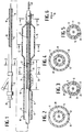
- FIGS. 1-5 schematically illustrate an over-the-wire, perfusion type dilatation catheter embodying features of the invention.
- the catheter includes an elongated catheter body 10 which has an inner tubular member 11 with an inner lumen 12, an outer tubular member 13 disposed about the inner tubular member and defining therebetween an annular inner lumen 14 which extends through the proximal portion of the catheter body.
- An adapter 15 is secured to the proximal ends of the inner and outer tubular members 11 and 13.
- a relatively inelastic, inflatable balloon 16 is formed as part of the outer tubular member 13 with the distal end of the balloon secured to the distal end of the inner tubular member 11.
- the balloon 16 may be formed from the same tubing as the outer tubular member 13 as shown in FIG. 1 or it may be made separately from the same or different materials and secured to the distal end of the outer tubular member as is well known to those skilled in the art.
- a helical coil 17 formed of flat ribbon 18 is disposed within the inner tubular member 11 and extends therein between the ends of the balloon 16.
- a transverse cross section of the ribbon 18 is shown in Fig 6 illustrating the rectangular shape thereof.
- the cross-sectional dimensions of the ribbon 18 are about 0.0015 inch (0.038 mm) thick and about 0.01 inch (0.25 mm) in width, although other dimensions may be employed depending upon the strength of the material from which the coil 17 is made and upon the needs of the particular balloon dilatation procedure.
- the individual turns of the coil 17 are preferably stacked adjacent to one another, the coil may be stretched to provide space between the individual turns of the coil.
- the outer tubular member 13 generally has a distal section 19 with small transverse dimensions in at least one direction. As best shown in FIGS. 1 and 3, a length 20 of the distal section 19 is bonded to the exterior of the inner tubular member 11 with a significant portion of the periphery outer member 13, typically about 50% to about 80%, being bonded to the inner tubular member.
- the unbonded portion 21 of the distal section 19 along the length 20 forms an inflation lumen 21 which is in fluid communication with the interior of the balloon 16 and the annular lumen 14.
- a plurality of perfusion ports 23 proximal to the balloon 16 which pass through the bonded walls 24 and 25 of the inner and outer tubular members 11 and 13, respectively, and which are in fluid communication with the inner lumen 12 of the inner tubular member 11.
- one or more perfusion ports 26 are provided distal to the balloon 16 through the wall 27 of the inner tubular member 11 and are in fluid communication with the inner lumen 12 extending therein.
- oxygenated blood is forced to pass through the proximal perfusion ports 23, through the inner lumen 12 and then out the distal perfusion ports 26 to provide oxygenated blood distal to the catheter and thereby avoid the generation of ischemic conditions in tissue downstream thereof.
- the transverse dimensions of the inner lumen 12 of the tubular member 11 within the bonded section should be large enough to allow for an adequate flow of blood therethrough when the guidewire 28 is withdrawn sufficiently from the perfusion portion of the inner lumen 12 to avoid impeding blood flow.
- FIGS. 1-6 generally follows conventional PTCA practices with over-the-wire perfusion-type dilatation catheters.
- a guidewire 28 is backloaded into the inner lumen 12 of the inner tubular member 11 of the catheter body 10 and both the guidewire and the catheter are advanced together through a guiding catheter (not shown) which has been previously disposed within the patient's arterial system, with the distal end of the guiding catheter seated within the ostium of the desired coronary artery.
- the guidewire 28 is advanced out the distal end of the guiding catheter into the patient's coronary anatomy until it crosses the lesion to be dilated, and then the dilatation catheter is advanced over the guidewire which is being held in its position, until the balloon 16 on the dilatation catheter is properly disposed within the stenotic region.
- the lesion is dilated by directing inflation fluid through the annular lumen 14 and the inflation lumen 22 formed by the unbonded portion of the outer tubular member 13 to inflate the balloon 16.
- the balloon 16 can be maintained in the inflated condition for long periods, e.g. typically about 20-30 minutes but in some instances up to 5 hours or more.
- the balloon 16 occludes the arterial lumen causing oxygenated blood within the coronary artery to flow through the proximal perfusion ports 23 into the inner lumen 12 and out the distal perfusion ports 26 to tissue distal to the inflated balloon so as to prevent or minimize the severity of ischemic conditions at the distal location.
- the guidewire 28 is pulled back into the inner lumen 12 of the catheter to a location therein so that the distal end of the guidewire is proximal to the proximal perfusion ports 23 to avoid interference with the flow of blood through the inner lumen 12.
- the balloon 16 is deflated and the catheter and the guidewire 28 may then be withdrawn from the patient.
- the guidewire can be replaced with an exchange wire before removing the dilatation catheter so that the first catheter can be removed and another advanced into the desired location or an extension wire can be attached to the proximal end of the guidewire in place to perform essentially the same function. See the discussion of exchange wires and extension wires in U.S. Patent 4,827,941 (Taylor et al .).
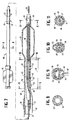
- FIGS. 7-11 schematically illustrate another embodiment of the perfusion dilatation catheter of the invention.
- the catheter includes a body 30 having an outer tubular member 31 with a two layered proximal portion 32 which has an outer plastic tubular coating or jacket 33 which fits tightly, e.g. is shrunk fit, onto an inner tubular element 34 which is preferably formed of hypotubing.
- An adapter 35 is secured to the proximal end of the catheter body 30.
- the proximal skirt 36 of the relatively inelastic balloon 37 is secured to the distal end of the outer plastic element 33.
- the distal skirt 38 of the balloon 37 is bonded to the distal end of the inner tubular member 39.
- the catheter body 30 has a flexible distal section 40 where a significant portion of the interior surface of the proximal skirt 36 of the balloon 37 along a length 41 is bonded to the exterior of the inner tubular member 39.
- a plurality of perfusion ports 42 extend through the bonded walls 43 and 44 of the balloon skirt 36 and the inner tubular member 39, respectively and are in fluid communication with inner lumen 45 of the inner tubular member 39.
- the distal end of this embodiment is quite similar to the embodiment shown in FIGS. 1-6.
- the catheter body 30 is provided a proximal guidewire port 46 which passes through the bonded walls 43 and 44 of the balloon skirt 36 and the inner tubular member 39 respectively and which is in fluid communication with a relatively short inner lumen 45 extending within the distal portion of the inner tubular member 39.
- a distal guidewire port 47 is provided at the distal end of the inner tubular member 39 in communication with the inner lumen 45 thereof.
- Guidewire 48 extends proximally through the inner lumen 45 and out the proximal port 46 and the coil 49 on the distal end of the guidewire 48 extends out the distal port 47 in the distal end of the inner tubular member 39.
- a supporting helical coil 50 is disposed within the inner lumen 45 of the tubular member 39 and extends between the proximal and distal ends of the balloon 37 and preferably between the proximal perfusion ports 42 and the distal perfusion ports 51.
- the inner tubular element 34 onto which the outer plastic jacket 33 is secured is preferably hypotubing and may be formed of stainless steel, such as 304 alloy, or of a NiTi alloy, particularly a NiTi alloy with superelastic properties.
- the distal extremity of the inner tubular element 34 is truncated to fit well into the inner lumen 52 in the proximal portion of the proximal skirt 36 of the balloon 37 which is not bonded to the inner tubular member 39 to direct inflation fluid to the interior of the balloon.
- a slit 53 is preferably provided in the bonded walls 43 and 44 of the inner tubular member 39 and the proximal skirt 36 extending from the proximal guidewire port 46 to a location adjacent the proximal end of the balloon 37, preferably through the proximal perfusion ports 42.
- the slit 53 greatly facilitates the removal of the catheter from the proximal end of the guidewire 48 when the catheter is to be replaced or exchanged for another catheter and it also eliminates the need for using a guidewire extension or an exchange wire as described in Horzewski et al .
- the first method is for the most part the same as in the prior embodiment, namely, the guidewire 48 is preloaded into the short inner lumen 45 of the inner tubular member 39 of the catheter body 30 and both are advanced through a guiding catheter (not shown) previously disposed within the patient's arterial system with the distal end of the guiding catheter seated within the ostium of the desired coronary artery.
- the second mode frequently called the "bare wire” technique, involves first advancing a guidewire 48 through and out the guiding catheter until it is positioned within the patient's coronary artery across the lesion to be dilated.
- the proximal end of the guidewire 48 which is outside the patient, is backloaded, i.e . inserted into the short inner lumen 45 of the inner tubular member 39 and advanced proximally therein until it exits the proximal guidewire port 46.
- the proximal end of the guidewire 48 is held in place and the catheter is advanced over the guidewire through the patient's vascular system until the dilatation balloon 37 on the catheter is positioned across the stenotic region so that the stenosis can be dilated upon the inflation of the balloon.
- the inflated balloon 37 occludes the arterial passageway causing blood to flow through the proximal perfusion ports 42 into the inner lumen 45 and out the distal perfusion ports 51 to minimize ischemic conditions in tissue distal to the balloon.
- the balloon can be maintained in the inflated condition for extended periods.
- the balloon 37 is deflated and the catheter may be removed from the patient's artery. If other treatments are necessary, the catheter is slidably removed over the guidewire 48, leaving the guidewire in place so that other catheters can be advanced over the in-place guidewire in a similar manner without the need for exchange wires or guidewire extensions.
- the above described perfusion-type catheters may be made by conventional techniques well known to those skilled in the art, and many of these suitable techniques are described in the references incorporated herein.
- the bonded distal sections 19 and 40 may be formed by heat shrinking the portion of the outer tubular members 13 and proximal skirt 36 which form the distal sections onto the underlying inner members 11 and 39.
- a mandrel (not shown) is disposed in the space between the inner and outer tubular members 11 and 13 and the skirt 36 and the inner tubular member 39 so that upon the heat shrinking of the outer tubular member or skirt an inflation lumen is formed through the distal sections which is in fluid communication with the lumen in the proximal portion of the catheter body and the interior of the balloon.
- Another mandrel may be inserted into the inner lumen of the inner tubular member to support and shape the latter during the heat shrinking of the outer tubular member thereon.
- Alternate methods may be employed to make the distal section.
- the distal sections 19 and 40 may be preformed and then be adhesively bonded to the exterior of the inner tubular member.
- Multiple lumens similar to the inflation lumen may be formed in the distal sections, such as the top and bottom thereof, by employing multiple mandrels when heat shrinking the outer tubular member onto the exterior of the inner tubular member.
- the various components of the catheters and guidewires of the invention can be formed from a wide variety of conventional materials.
- the inner and outer plastic tubular members may be made from polyethylene, polyesters, polyimide, polyvinyl chloride and other suitable plastic materials.
- the hypotubing may be formed of stainless steel, NiTi superelastic alloys or other suitable materials. Composite materials may also be used.
- the balloon may be made from polyethylene, polyethylene terephthalate and other suitable polymers and other materials.
- the dimensions of the catheters generally follow the dimensions of conventional intravascular catheters.
- the length is typically about 135 cm and the outer diameter of the outer tubular member is about 0.05 - 0.15 cm (0.02 to about 0.06 inch.)
- the inner tubular member into which the coil or other support is disposed generally has an inner lumen with a diameter of about 0.015 to about 0.035 inch (0.38-0.89 mm) and a wall thickness of up to about 0.0015 inch (0.38 mm) and preferably about 0.0008 to about 0.0012 inch (0.02 - 0.03 mm).
- the flexible distal section is long enough ( e.g.
- the proximal end of the distal section is preferably about 15 to about 40 cm from the distal end of the catheter) to ensure that the distal section is the only portion of the catheter body proximal to the balloon which exits the guiding catheter and enters the patient's coronary anatomy during intravascular procedures.
- the transverse dimensions of the catheter may be larger for catheters used in peripheral arteries and other locations.
Abstract
Description
- This invention generally relates to intravascular catheters, such as balloon dilatation catheters used in percutaneous transluminal coronary angioplasty (PTCA).
- In classic PTCA procedures, a guiding catheter having a preshaped distal tip is percutaneously introduced into the cardiovascular system of a patient and advanced therein until the preshaped distal tip of the guiding catheter is disposed within the aorta adjacent to the ostium of the desired coronary artery. The guiding catheter is twisted or torqued from the proximal end to turn the distal tip of the guiding catheter so that it can be guided into the coronary ostium. A guidewire and a balloon dilatation catheter are introduced into and advanced through the guiding catheter to the distal tip thereof, with the guidewire slidably disposed within an inner lumen of the dilatation catheter. The guidewire is first advanced out the distal tip of the guiding catheter, which is seated in the ostium of the patient's coronary artery, until the distal end of the guidewire crosses the lesion to be dilated. The dilatation catheter is then advanced out of the distal tip of the guiding catheter, over the previously advanced guidewire, until the balloon on the distal extremity of the dilatation catheter is properly positioned across the lesion. Once properly positioned, the balloon is inflated to a predetermined size with radiopaque liquid at relatively high pressures (e.g., generally 4-12 atmospheres) to dilate the stenosed region of the diseased artery. The balloon is then deflated so that the dilatation catheter can be removed from the dilated stenosis and blood flow will resume therethrough.
- Further details of guiding catheters, dilatation catheters, guidewires, and other devices for angioplasty procedures can be found in U.S. Patent 4,323,071 (Simpson-Robert); U.S. Patent 4,439,185 (Lundquist); U.S. Patent 4,468,224 (Enzmann et al.); U.S. Patent 4,516,972 (Samson); U.S. Patent 4,554,929 (Samson et al.); U.S. Patent 4,616,652 (Simpson); U.S. Patent 4,638,805 (Powell); U.S. Patent 4,748,986 (Morrison et al.); U.S. Patent 4,898,577 (Badger et al.); and U.S.Patent 4,827,943 (Taylor et al.).
- Several notable improvements have recently been made in balloon angioplasty catheters. One such modification is described in U.S. Patent 4,748,982 (Horzewski et al.) wherein a short sleeve or inner lumen at least about 10 cm in length is provided within the distal section of the catheter body which extends from a first port proximal to the balloon to a second port in the distal end of the catheter and which is adapted to slidably receive a guidewire. The proximal port is not less than about 10 cm and not more than about 40 cm from the distal end of the catheter. Preferably, a slit is provided in the catheter body extending from the proximal port to a location proximal to the proximal end of the balloon to facilitate the removal of the catheter from the proximal end of the guidewire which extends out of the patient.
- Another modification, which was introduced into the market place by the assignee of the present application (Advanced Cardiovascular Systems, Inc.), has been perfusion-type dilatation catheters which allow for long term dilatations to repair arterial dissections and other arterial damage. These perfusion catheters have a plurality of perfusion ports in the wall forming at least part of the catheter body proximal to the balloon which are in fluid communication with an inner lumen extending to the distal end of the catheter body. A plurality of perfusion ports are preferably provided in the catheter body distal to the balloon which are also in fluid communication with the inner lumen extending to the distal end of the catheter body. When the balloon on the distal extremity of the dilatation catheter is inflated to dilate a stenosis, oxygenated blood in the artery or the aorta or both, depending upon the location of the dilatation catheter within the coronary anatomy, is forced to pass through the proximal perfusion ports, through the inner lumen of the catheter body and out the distal perfusion ports. This provides oxygenated blood downstream from the inflated balloon to thereby prevent or minimize ischemic conditions in tissue distal to the catheter to thereby facilitate long term dilatations. As is appreciated by those skilled in the art, tissue distal to a stenosis is frequently already in jeopardy due to ischemic conditions which may exist. As a result, care should be exercised in sizing the perfusion ports and the inner lumen to ensure that there is adequate flow of oxygenated blood to tissue distal to the catheter to eliminate or minimize ischemic conditions. Unfortunately, commercially available perfusion catheters have relatively large profiles due to the size of the inner tubular member which extends through the interior of the balloon which prevents their use in many distal coronary locations.
- A major and continual thrust of development work in the field of intravascular catheters, particularly coronary angioplasty catheters, has been to reduce the profile, i.e. transverse dimensions, of such catheters and to improve the flexibility thereof without detrimentally affecting the pushability, particularly in the distal portion of such catheters. A reduction in profile with little or no loss in pushability allows a dilatation catheter to be advanced much further into a patient's coronary vasculature and to cross much tighter lesions.
- A Prior Art document, US-A-4748982 discloses a reinforced balloon dilatation catheter having an elongated catheter body having proximal and distal ends, and an inner lumen extending from the proximal end to the distal end thereof and distal section disposed at the distal end of said elongated catheter body, having a first lumen which is in fluid communication with the inner lumen of said elongated catheter body, a second lumen which is defined by a tubular member, and an inflatable balloon having proximal and distal ends, and an interior which is in fluid communication with the first lumen of the distal section.
- Despite many advances in this field, a need remains for lower profile, perfusion type dilatation catheters having greater flexibility with little or no loss in pushability. The present invention satisfies this need.
- This invention is directed to an improved balloon angioplasty catheter which is adapted to perfuse blood distal to the catheter when the balloon thereon is inflated during an angioplasty procedure.
- According to the present invention there is provided a balloon dilatation catheter adapted to be advanced within a patient's arterial system, comprising:
- (a) an elongated catheter body having proximal and distal ends and an inner lumen extending from the proximal end to the distal end thereof,
- (b) a distal section disposed at the distal end of said elongated catheter body having a first lumen which is in fluid communication with the inner lumen of said elongated catheter body, a second lumen which is defined by a tubular member, and an inflatable balloon having proximal and distal ends and an interior which is in fluid communication with said first lumen of the distal section,
- (c) at least one distal perfusion port distal of the balloon and at least one proximal perfusion port proximal of the balloon whereby said catheter, when in use, is adapted to perfuse blood to an arterial location distal of the catheter upon inflation of the balloon;
- (d) said second lumen having a helical coil member disposed therein to extend from a first location to a second location, said first location being distal to said proximal perfusion port and proximal to the inflatable dilatation balloon and said second location being distal to the proximal end of the balloon.
-
- The supporting member for the thin walled tubular element preferably extends beyond both ends, of the inflatable member to facilitate a smooth transition between the inflatable member and adjacent sections of the catheter and thereby improve the trackability of the catheter over a guidewire. A suitable helical coil is a helical coil formed of flat ribbon of high strength metal such as stainless steel, e.g. 304 alloy, and Nitinol, particularly with superelastic properties. The transverse dimensions of the ribbon are about 0.0005 to about 0.002 inch (0.013-0.051 mm) in thickness and about 0.003 to about 0.01 inch (0.076-0.254 mm) in width. Although it is preferred to have the individual turns of the coil stacked against one another, the coil may be extended up to 50% of its length when the turns are stacked against one another.
- The catheter shaft of the dilatation catheter described elsewhere has a distal section with an inner tubular member having an inner lumen extending therein and an outer tubular member disposed about the inner tubular member. In the distal section, a length of the outer tubular member is bonded by a substantial part of the inner surface or inner periphery thereof to the outer surface of the inner tubular member. At least about 15% to about 90%, preferably about 40% to about 80%, of the periphery of the outer tubular member is bonded to the underlying inner tubular member so that the bonded portion of the outer member takes the shape of the inner tubular member to which it is bonded. The unbonded portion of the outer tubular member along said length defines with the inner tubular member a longitudinally extending inner lumen.
- The bond between the inner and outer tubular members need not be continuous, i.e. may be intermittent, so long as a significant portion thereof is bonded. The bonded section may extend along essentially the entire length of the catheter but should not be less than about 1 cm. Preferably, the length of the bonded section is about 10 cm to about 40 cm. By bonding a length of the outer tubular member in the distal portion of the catheter to the exterior of the inner member, the profile of the catheter body in at least one transverse dimension in that area is reduced substantially to thereby provide improved flexibility. Moreover, the bonded portions of the inner member and the outer tubular members support one another thereby providing an improvement in the pushability of the catheter. Substantial reductions in only one transverse dimensions can provide substantial improvements is flexibility. Minimum cross-sectional dimensions of the distal section of the catheter body for coronary dilatation catheters are on the order of about 0.02 to about 0.06 inch (0.51 - 1.5 mm). For peripheral arteries this dimension may be larger.
- The coil supported, thin walled inner tubular member which is adapted to perfuse blood through the interior of the balloon has little tendency to collapse upon the inflation of the balloon, even to inflation pressures of 2.4x10⁶Pa (350 psi) or more. Additionally, the coil support provides much smoother transitions which result in improved trackability of the catheter over a guidewire. These and other advantages of the invention will become more apparent from the following detailed description of the invention when taken in conjunction with the accompanying exemplary drawings.
-
- FIG. 1 is an elevational view, partially in section, of a perfusion-type balloon dilatation catheter embodying features of the invention.
- FIG. 2 is a transverse cross-sectional view of the catheter shown in FIG. 1 taken along the lines 2-2.
- FIG. 3 is a transverse cross-sectional view of the catheter shown in FIG. 1 taken along the lines 3-3.
- FIG. 4 is a transverse cross-sectional view of the catheter shown in FIG. 1 taken along the lines 4-4.
- FIG. 5 is a transverse cross-sectional view of the catheter shown in FIG. 1 taken along the lines 5-5.
- FIG. 6 is a transverse cross-sectional view of the ribbon forming the helical coil disposed within the inner tubular member shown in FIGS. 1-5.
- FIG. 7 is an elevational view, partially in section, of another perfusion-type balloon dilatation catheter embodying features of the invention.
- FIG. 8 is a transverse cross-sectional view of the catheter shown in FIG. 7 taken along the lines 8-8.
- FIG. 9 is a transverse cross-sectional view of the catheter shown in FIG. 7 taken along the lines 9-9.
- FIG. 10 is a transverse cross-sectional view of the catheter shown in FIG. 7 taken along the lines 10-10.
- FIG. 11 is a transverse cross-sectional view of the catheter shown in FIG. 7 taken along the lines 11-11.
-
- FIGS. 1-5 schematically illustrate an over-the-wire, perfusion type dilatation catheter embodying features of the invention. The catheter includes an
elongated catheter body 10 which has aninner tubular member 11 with aninner lumen 12, anouter tubular member 13 disposed about the inner tubular member and defining therebetween an annularinner lumen 14 which extends through the proximal portion of the catheter body. Anadapter 15 is secured to the proximal ends of the inner and outertubular members inflatable balloon 16 is formed as part of the outertubular member 13 with the distal end of the balloon secured to the distal end of theinner tubular member 11. Theballoon 16 may be formed from the same tubing as the outertubular member 13 as shown in FIG. 1 or it may be made separately from the same or different materials and secured to the distal end of the outer tubular member as is well known to those skilled in the art. - A
helical coil 17 formed offlat ribbon 18 is disposed within theinner tubular member 11 and extends therein between the ends of theballoon 16. A transverse cross section of theribbon 18 is shown in Fig 6 illustrating the rectangular shape thereof. Typically, the cross-sectional dimensions of theribbon 18 are about 0.0015 inch (0.038 mm) thick and about 0.01 inch (0.25 mm) in width, although other dimensions may be employed depending upon the strength of the material from which thecoil 17 is made and upon the needs of the particular balloon dilatation procedure. While the individual turns of thecoil 17 are preferably stacked adjacent to one another, the coil may be stretched to provide space between the individual turns of the coil. - The outer
tubular member 13 generally has adistal section 19 with small transverse dimensions in at least one direction. As best shown in FIGS. 1 and 3, alength 20 of thedistal section 19 is bonded to the exterior of theinner tubular member 11 with a significant portion of the peripheryouter member 13, typically about 50% to about 80%, being bonded to the inner tubular member. Theunbonded portion 21 of thedistal section 19 along thelength 20 forms aninflation lumen 21 which is in fluid communication with the interior of theballoon 16 and theannular lumen 14. A plurality ofperfusion ports 23 proximal to theballoon 16 which pass through the bondedwalls tubular members inner lumen 12 of theinner tubular member 11. Additionally, one ormore perfusion ports 26 are provided distal to theballoon 16 through thewall 27 of theinner tubular member 11 and are in fluid communication with theinner lumen 12 extending therein. In this manner, when theballoon 16 is inflated during an angioplasty procedure within a patient's vasculature, oxygenated blood is forced to pass through theproximal perfusion ports 23, through theinner lumen 12 and then out thedistal perfusion ports 26 to provide oxygenated blood distal to the catheter and thereby avoid the generation of ischemic conditions in tissue downstream thereof. The transverse dimensions of theinner lumen 12 of thetubular member 11 within the bonded section should be large enough to allow for an adequate flow of blood therethrough when theguidewire 28 is withdrawn sufficiently from the perfusion portion of theinner lumen 12 to avoid impeding blood flow. - The use of the dilatation catheter shown in FIGS. 1-6 generally follows conventional PTCA practices with over-the-wire perfusion-type dilatation catheters. A
guidewire 28 is backloaded into theinner lumen 12 of theinner tubular member 11 of thecatheter body 10 and both the guidewire and the catheter are advanced together through a guiding catheter (not shown) which has been previously disposed within the patient's arterial system, with the distal end of the guiding catheter seated within the ostium of the desired coronary artery. Theguidewire 28 is advanced out the distal end of the guiding catheter into the patient's coronary anatomy until it crosses the lesion to be dilated, and then the dilatation catheter is advanced over the guidewire which is being held in its position, until theballoon 16 on the dilatation catheter is properly disposed within the stenotic region. The lesion is dilated by directing inflation fluid through theannular lumen 14 and the inflation lumen 22 formed by the unbonded portion of the outertubular member 13 to inflate theballoon 16. Theballoon 16 can be maintained in the inflated condition for long periods, e.g. typically about 20-30 minutes but in some instances up to 5 hours or more. Upon inflation, theballoon 16 occludes the arterial lumen causing oxygenated blood within the coronary artery to flow through theproximal perfusion ports 23 into theinner lumen 12 and out thedistal perfusion ports 26 to tissue distal to the inflated balloon so as to prevent or minimize the severity of ischemic conditions at the distal location. Preferably, theguidewire 28 is pulled back into theinner lumen 12 of the catheter to a location therein so that the distal end of the guidewire is proximal to theproximal perfusion ports 23 to avoid interference with the flow of blood through theinner lumen 12. After the dilatation, theballoon 16 is deflated and the catheter and theguidewire 28 may then be withdrawn from the patient. If further treatment or diagnosis is to be conducted, the guidewire can be replaced with an exchange wire before removing the dilatation catheter so that the first catheter can be removed and another advanced into the desired location or an extension wire can be attached to the proximal end of the guidewire in place to perform essentially the same function. See the discussion of exchange wires and extension wires in U.S. Patent 4,827,941 (Taylor et al.). - FIGS. 7-11 schematically illustrate another embodiment of the perfusion dilatation catheter of the invention. In this embodiment the catheter includes a
body 30 having anouter tubular member 31 with a two layeredproximal portion 32 which has an outer plastic tubular coating orjacket 33 which fits tightly, e.g. is shrunk fit, onto an innertubular element 34 which is preferably formed of hypotubing. Anadapter 35 is secured to the proximal end of thecatheter body 30. Theproximal skirt 36 of the relativelyinelastic balloon 37 is secured to the distal end of the outerplastic element 33. Thedistal skirt 38 of theballoon 37 is bonded to the distal end of theinner tubular member 39. Thecatheter body 30 has a flexibledistal section 40 where a significant portion of the interior surface of theproximal skirt 36 of theballoon 37 along alength 41 is bonded to the exterior of theinner tubular member 39. A plurality ofperfusion ports 42 extend through the bondedwalls balloon skirt 36 and theinner tubular member 39, respectively and are in fluid communication withinner lumen 45 of theinner tubular member 39. To this extent, the distal end of this embodiment is quite similar to the embodiment shown in FIGS. 1-6. - In the embodiment shown in FIGS. 7-11, the
catheter body 30 is provided aproximal guidewire port 46 which passes through the bondedwalls balloon skirt 36 and theinner tubular member 39 respectively and which is in fluid communication with a relatively shortinner lumen 45 extending within the distal portion of theinner tubular member 39. Adistal guidewire port 47 is provided at the distal end of theinner tubular member 39 in communication with theinner lumen 45 thereof.Guidewire 48 extends proximally through theinner lumen 45 and out theproximal port 46 and thecoil 49 on the distal end of theguidewire 48 extends out thedistal port 47 in the distal end of theinner tubular member 39. A supportinghelical coil 50 is disposed within theinner lumen 45 of thetubular member 39 and extends between the proximal and distal ends of theballoon 37 and preferably between theproximal perfusion ports 42 and thedistal perfusion ports 51. - The inner
tubular element 34 onto which the outerplastic jacket 33 is secured is preferably hypotubing and may be formed of stainless steel, such as 304 alloy, or of a NiTi alloy, particularly a NiTi alloy with superelastic properties. The distal extremity of the innertubular element 34 is truncated to fit well into theinner lumen 52 in the proximal portion of theproximal skirt 36 of theballoon 37 which is not bonded to theinner tubular member 39 to direct inflation fluid to the interior of the balloon. - The catheter construction of this embodiment with a relatively short inner lumen which is adapted to slidably receive a guidewire therein eliminates the need for using an exchange wire or a guidewire extension. A
slit 53 is preferably provided in the bondedwalls inner tubular member 39 and theproximal skirt 36 extending from theproximal guidewire port 46 to a location adjacent the proximal end of theballoon 37, preferably through theproximal perfusion ports 42. Theslit 53 greatly facilitates the removal of the catheter from the proximal end of theguidewire 48 when the catheter is to be replaced or exchanged for another catheter and it also eliminates the need for using a guidewire extension or an exchange wire as described in Horzewski et al. - There are at least two modes of inserting the dilatation catheter of this embodiment into the patient's coronary anatomy. The first method is for the most part the same as in the prior embodiment, namely, the
guidewire 48 is preloaded into the shortinner lumen 45 of theinner tubular member 39 of thecatheter body 30 and both are advanced through a guiding catheter (not shown) previously disposed within the patient's arterial system with the distal end of the guiding catheter seated within the ostium of the desired coronary artery. The second mode, frequently called the "bare wire" technique, involves first advancing aguidewire 48 through and out the guiding catheter until it is positioned within the patient's coronary artery across the lesion to be dilated. The proximal end of theguidewire 48, which is outside the patient, is backloaded, i.e. inserted into the shortinner lumen 45 of theinner tubular member 39 and advanced proximally therein until it exits theproximal guidewire port 46. The proximal end of theguidewire 48 is held in place and the catheter is advanced over the guidewire through the patient's vascular system until thedilatation balloon 37 on the catheter is positioned across the stenotic region so that the stenosis can be dilated upon the inflation of the balloon. Theinflated balloon 37 occludes the arterial passageway causing blood to flow through theproximal perfusion ports 42 into theinner lumen 45 and out thedistal perfusion ports 51 to minimize ischemic conditions in tissue distal to the balloon. As in the previously discussed embodiment, the balloon can be maintained in the inflated condition for extended periods. After the dilatation of the lesion, theballoon 37 is deflated and the catheter may be removed from the patient's artery. If other treatments are necessary, the catheter is slidably removed over theguidewire 48, leaving the guidewire in place so that other catheters can be advanced over the in-place guidewire in a similar manner without the need for exchange wires or guidewire extensions. - The above described perfusion-type catheters may be made by conventional techniques well known to those skilled in the art, and many of these suitable techniques are described in the references incorporated herein. The bonded
distal sections tubular members 13 andproximal skirt 36 which form the distal sections onto the underlyinginner members tubular members skirt 36 and theinner tubular member 39 so that upon the heat shrinking of the outer tubular member or skirt an inflation lumen is formed through the distal sections which is in fluid communication with the lumen in the proximal portion of the catheter body and the interior of the balloon. Another mandrel may be inserted into the inner lumen of the inner tubular member to support and shape the latter during the heat shrinking of the outer tubular member thereon. Alternate methods may be employed to make the distal section. For example, thedistal sections - The various components of the catheters and guidewires of the invention can be formed from a wide variety of conventional materials. The inner and outer plastic tubular members may be made from polyethylene, polyesters, polyimide, polyvinyl chloride and other suitable plastic materials. The hypotubing may be formed of stainless steel, NiTi superelastic alloys or other suitable materials. Composite materials may also be used. The balloon may be made from polyethylene, polyethylene terephthalate and other suitable polymers and other materials.
- The dimensions of the catheters generally follow the dimensions of conventional intravascular catheters. For coronary use the length is typically about 135 cm and the outer diameter of the outer tubular member is about 0.05 - 0.15 cm (0.02 to about 0.06 inch.) The inner tubular member into which the coil or other support is disposed generally has an inner lumen with a diameter of about 0.015 to about 0.035 inch (0.38-0.89 mm) and a wall thickness of up to about 0.0015 inch (0.38 mm) and preferably about 0.0008 to about 0.0012 inch (0.02 - 0.03 mm). In a presently preferred embodiment, the flexible distal section is long enough (e.g. the proximal end of the distal section is preferably about 15 to about 40 cm from the distal end of the catheter) to ensure that the distal section is the only portion of the catheter body proximal to the balloon which exits the guiding catheter and enters the patient's coronary anatomy during intravascular procedures. The transverse dimensions of the catheter may be larger for catheters used in peripheral arteries and other locations.
- Those skilled in the art will recognize that modifications and improvements can be made to the invention without departing from the scope thereof as defined in the appended claims.
Claims (9)
- A balloon dilatation catheter adapted to be advanced within a patient's arterial system, comprising:(a) an elongated catheter body (10,30) having proximal and distal ends and an inner lumen (14,34) extending from the proximal end to the distal end thereof,(b) a distal section disposed at the distal end of said elongated catheter body having a first lumen (21,52) which is in fluid communication with the inner lumen of said elongated catheter body, a second lumen (12,45) which is defined by a tubular member, and an inflatable balloon (16,37) having proximal and distal ends and an interior which is in fluid communication with said first lumen of the distal section,(c) at least one distal perfusion port (26,51) distal of the balloon and at least one proximal perfusion port (23,42) proximal of the balloon whereby said catheter, when in use, is adapted to peruse blood to an arterial location distal of the catheter upon inflation of the balloon;(d) said second lumen having a helical coil member (17,50) disposed therein to extend from a first location to a second location, said first location being distal to said proximal perfusion port and proximal to the inflatable dilatation balloon and said second location being distal to the proximal end of the balloon.
- The balloon dilation catheter of claim 1 wherein the coil member (17,50) disposed within the second lumen is formed from ribbon.
- The balloon dilatation catheter of claim 2 wherein the ribbon is formed of material selected from the group consisting of stainless steel and NiTi alloys having superelastic properties.
- The balloon dilatation catheter of claim 1 wherein the coil member (17,50) extends beyond both ends of the inflatable dilatation balloon.
- The balloon dilatation catheter of claim 1 wherein the coil member (17,50) fits tightly within the second lumen.
- The balloon dilatation catheter of claim 5 wherein the distal element is heat shrunk so that the coil member (17,50) fits tightly within the second lumen thereof.
- The balloon dilatation catheter of claim 1 wherein the distal section has a guidewire receiving port (46) located proximal to the proximal perfusion port which is in fluid communication with the seconds lumen therein.
- The balloon dilatation catheter of claim 6 wherein the distal section has a guidewire receiving port (47) located in the distal end of the second lumen and in fluid communication therewith.
- The balloon dilatation catheter of claim 1 wherein the second lumen is adapted to receive a guidewire (48) and extends between a first guidewire port (46) in a proximal portion of the distal section and a second guidewire port (47) in a distal portion of the distal section.
Applications Claiming Priority (3)
| Application Number | Priority Date | Filing Date | Title |
|---|---|---|---|
| US73489291A | 1991-07-24 | 1991-07-24 | |
| US734892 | 1991-07-24 | ||
| PCT/US1992/006121 WO1993001856A1 (en) | 1991-07-24 | 1992-07-23 | Low profile perfusion-type dilatation catheter |
Publications (3)
| Publication Number | Publication Date |
|---|---|
| EP0600940A1 EP0600940A1 (en) | 1994-06-15 |
| EP0600940A4 EP0600940A4 (en) | 1994-07-20 |
| EP0600940B1 true EP0600940B1 (en) | 1999-02-24 |
Family
ID=24953474
Family Applications (1)
| Application Number | Title | Priority Date | Filing Date |
|---|---|---|---|
| EP92916870A Expired - Lifetime EP0600940B1 (en) | 1991-07-24 | 1992-07-23 | Low profile perfusion-type dilatation catheter |
Country Status (6)
| Country | Link |
|---|---|
| US (1) | US5279562A (en) |
| EP (1) | EP0600940B1 (en) |
| JP (1) | JPH09507391A (en) |
| CA (1) | CA2114010A1 (en) |
| DE (1) | DE69228478T2 (en) |
| WO (1) | WO1993001856A1 (en) |
Families Citing this family (163)
| Publication number | Priority date | Publication date | Assignee | Title |
|---|---|---|---|---|
| US5599296A (en) * | 1991-02-14 | 1997-02-04 | Wayne State University | Apparatus and method of delivery of gas-supersaturated liquids |
| US5730935A (en) * | 1984-07-12 | 1998-03-24 | Wayne State University | High pressure gas exchanger |
| US5569180A (en) * | 1991-02-14 | 1996-10-29 | Wayne State University | Method for delivering a gas-supersaturated fluid to a gas-depleted site and use thereof |
| US5693017A (en) * | 1991-02-14 | 1997-12-02 | Wayne State University | Apparatus and method of delivery of gas-supersaturated solutions to a delivery site |
| US5743875A (en) * | 1991-05-15 | 1998-04-28 | Advanced Cardiovascular Systems, Inc. | Catheter shaft with an oblong transverse cross-section |
| US5833706A (en) * | 1991-07-05 | 1998-11-10 | Scimed Life Systems, Inc. | Single operator exchange perfusion catheter having a distal catheter shaft section |
| US5976107A (en) | 1991-07-05 | 1999-11-02 | Scimed Life Systems. Inc. | Catheter having extendable guide wire lumen |
| WO1994014495A1 (en) * | 1992-12-18 | 1994-07-07 | Cardiovascular Dynamics, Inc. | Reinforced lumen catheter |
| JP3345147B2 (en) * | 1993-01-26 | 2002-11-18 | テルモ株式会社 | Vasodilators and catheters |
| US5464394A (en) * | 1993-06-08 | 1995-11-07 | American Biomed, Inc. | Multilumen percutaneous angioscopy catheter |
| US5344402A (en) * | 1993-06-30 | 1994-09-06 | Cardiovascular Dynamics, Inc. | Low profile perfusion catheter |
| EP0746374B1 (en) * | 1993-10-07 | 2003-12-10 | Boston Scientific Corporation | Dilatation catheter |
| US5383890A (en) * | 1993-10-27 | 1995-01-24 | Baxter International Inc. | Low-profile single-lumen perfusion balloon catheter |
| US5545138A (en) * | 1994-02-28 | 1996-08-13 | Medtronic, Inc. | Adjustable stiffness dilatation catheter |
| US5591129A (en) * | 1994-03-02 | 1997-01-07 | Scimed Life Systems, Inc. | Perfusion balloon angioplasty catheter |
| US7087039B1 (en) | 1994-03-02 | 2006-08-08 | Scimed Life Systems, Inc. | Perfusion balloon angioplasty catheter |
| US5891090A (en) * | 1994-03-14 | 1999-04-06 | Advanced Cardiovascular Systems, Inc. | Perfusion dilatation catheter with expanded support coil |
| US5902290A (en) * | 1994-03-14 | 1999-05-11 | Advanced Cardiovascular Systems, Inc. | Catheter providing intraluminal access |
| US5498240A (en) | 1994-05-27 | 1996-03-12 | Advanced Cardiovascular Systems, Inc. | Intravascular catheter with a replaceable shaft section |
| JP3970341B2 (en) † | 1994-06-20 | 2007-09-05 | テルモ株式会社 | Vascular catheter |
| JPH10503673A (en) * | 1994-06-24 | 1998-04-07 | アドバンスト・カーディオバスキュラー・システムズ・インコーポレイテッド | Catheter with reusable proximal body |
| US5695457A (en) * | 1994-07-28 | 1997-12-09 | Heartport, Inc. | Cardioplegia catheter system |
| DE69531101T2 (en) * | 1995-02-24 | 2004-04-08 | Ave Connaught | REINFORCED, REPLACEABLE BALLOON CATHETER |
| US5549552A (en) * | 1995-03-02 | 1996-08-27 | Scimed Life Systems, Inc. | Balloon dilation catheter with improved pushability, trackability and crossability |
| US5556382A (en) * | 1995-08-29 | 1996-09-17 | Scimed Life Systems, Inc. | Balloon perfusion catheter |
| US20030069522A1 (en) * | 1995-12-07 | 2003-04-10 | Jacobsen Stephen J. | Slotted medical device |
| US6102903A (en) * | 1995-12-14 | 2000-08-15 | Medtronics, Inc. | Device and method for selectively delivering fluid into an anatomical lumen |
| WO1997032626A2 (en) * | 1996-03-07 | 1997-09-12 | Scimed Life Systems, Inc. | Perfusion balloon angioplasty catheter |
| US6440088B1 (en) * | 1996-05-24 | 2002-08-27 | Precision Vascular Systems, Inc. | Hybrid catheter guide wire apparatus and method |
| US5833659A (en) * | 1996-07-10 | 1998-11-10 | Cordis Corporation | Infusion balloon catheter |
| US5782740A (en) * | 1996-08-29 | 1998-07-21 | Advanced Cardiovascular Systems, Inc. | Radiation dose delivery catheter with reinforcing mandrel |
| US6520951B1 (en) * | 1996-09-13 | 2003-02-18 | Scimed Life Systems, Inc. | Rapid exchange catheter with detachable hood |
| US6346093B1 (en) | 1996-09-13 | 2002-02-12 | Scimed Life Systems, Inc. | Single operator exchange biliary catheter with common distal lumen |
| US6007522A (en) * | 1996-09-13 | 1999-12-28 | Boston Scientific Corporation | Single operator exchange biliary catheter |
| US6096009A (en) * | 1996-09-13 | 2000-08-01 | Boston Scientific Corporation | Guidewire and catheter locking device and method |
| US6582401B1 (en) * | 1996-09-13 | 2003-06-24 | Scimed Life Sytems, Inc. | Multi-size convertible catheter |
| US6606515B1 (en) * | 1996-09-13 | 2003-08-12 | Scimed Life Systems, Inc. | Guide wire insertion and re-insertion tools and methods of use |
| US5921971A (en) | 1996-09-13 | 1999-07-13 | Boston Scientific Corporation | Single operator exchange biliary catheter |
| US6083232A (en) * | 1996-09-27 | 2000-07-04 | Advanced Cardivascular Systems, Inc. | Vibrating stent for opening calcified lesions |
| US5690613A (en) * | 1996-12-06 | 1997-11-25 | Medtronic, Inc. | Rapid exchange high pressure transition for high pressure catheter with non-compliant balloon |
| US6110097A (en) * | 1997-03-06 | 2000-08-29 | Scimed Life Systems, Inc. | Perfusion balloon catheter with radioactive source |
| US5891154A (en) * | 1997-05-06 | 1999-04-06 | Advanced Cardiovascular System, Inc. | Passive perfusion stent delivery system |
| US6210312B1 (en) | 1997-05-20 | 2001-04-03 | Advanced Cardiovascular Systems, Inc. | Catheter and guide wire assembly for delivery of a radiation source |
| US5968013A (en) * | 1997-08-21 | 1999-10-19 | Scimed Life Systems, Inc. | Multi-function dilatation catheter |
| US6048338A (en) * | 1997-10-15 | 2000-04-11 | Scimed Life Systems, Inc. | Catheter with spiral cut transition member |
| US5891110A (en) * | 1997-10-15 | 1999-04-06 | Scimed Life Systems, Inc. | Over-the-wire catheter with improved trackability |
| US5989218A (en) * | 1997-11-18 | 1999-11-23 | Advanced Cardiovascular Systems, Inc. | Perfusion catheter with coil supported inner tubular member |
| WO2004011057A1 (en) * | 1998-02-07 | 2004-02-05 | Advanced Cardiovascular Systems, Inc. | Perfusion dilatation catherer with expanded support coil |
| US6224535B1 (en) | 1998-02-17 | 2001-05-01 | Advanced Cardiovascular Systems, Inc. | Radiation centering catheters |
| US6159140A (en) * | 1998-02-17 | 2000-12-12 | Advanced Cardiovascular Systems | Radiation shielded catheter for delivering a radioactive source and method of use |
| US6159139A (en) * | 1998-02-17 | 2000-12-12 | Advanced Cardiovascular Systems Inc. | Radiation delivery catheter with a spring wire centering mechanism |
| US6113579A (en) | 1998-03-04 | 2000-09-05 | Scimed Life Systems, Inc. | Catheter tip designs and methods for improved stent crossing |
| US6517515B1 (en) | 1998-03-04 | 2003-02-11 | Scimed Life Systems, Inc. | Catheter having variable size guide wire lumen |
| US6129700A (en) * | 1998-12-04 | 2000-10-10 | Advanced Cardiovascular Systems, Inc. | Contrast medium injection device and method of use |
| US6264630B1 (en) | 1998-12-23 | 2001-07-24 | Scimed Life Systems, Inc. | Balloon catheter having an oscillating tip configuration |
| US6319244B2 (en) | 1999-03-16 | 2001-11-20 | Chase Medical, L.P. | Catheter with flexible and rigid reinforcements |
| AU3749400A (en) * | 1999-03-16 | 2000-10-04 | Chase Medical Inc. | Catheter having varying resiliency balloon |
| US6605031B1 (en) | 1999-09-22 | 2003-08-12 | Advanced Cardiovascular Systems, Inc. | Stepped centering balloon for optimal radiation delivery |
| US6582417B1 (en) | 1999-09-22 | 2003-06-24 | Advanced Cardiovascular Systems, Inc. | Methods and apparatuses for radiation treatment |
| JP2001353225A (en) * | 2000-06-15 | 2001-12-25 | Terumo Corp | Catheter |
| US7811250B1 (en) * | 2000-02-04 | 2010-10-12 | Boston Scientific Scimed, Inc. | Fluid injectable single operator exchange catheters and methods of use |
| US7994449B2 (en) | 2000-02-16 | 2011-08-09 | Advanced Cardiovascular Systems, Inc. | Square-wave laser bonding |
| US7163504B1 (en) | 2000-02-16 | 2007-01-16 | Advanced Cardiovascular Systems, Inc. | Multi-lumen fluted balloon radiation centering catheter |
| US6409863B1 (en) | 2000-06-12 | 2002-06-25 | Scimed Life Systems, Inc. | Methods of fabricating a catheter shaft having one or more guidewire ports |
| US6475184B1 (en) | 2000-06-14 | 2002-11-05 | Scimed Life Systems, Inc. | Catheter shaft |
| US6306106B1 (en) | 2000-06-19 | 2001-10-23 | Advanced Cardiovascular Systems, Inc. | Diagnostic sheath for reduced embolic risk |
| US6527746B1 (en) * | 2000-08-03 | 2003-03-04 | Ev3, Inc. | Back-loading catheter |
| US7008535B1 (en) * | 2000-08-04 | 2006-03-07 | Wayne State University | Apparatus for oxygenating wastewater |
| US6595983B2 (en) | 2000-12-07 | 2003-07-22 | Jan K. Voda | Guide or diagnostic catheter for right coronary artery |
| US6623504B2 (en) | 2000-12-08 | 2003-09-23 | Scimed Life Systems, Inc. | Balloon catheter with radiopaque distal tip |
| US6893456B2 (en) * | 2000-12-22 | 2005-05-17 | Advanced Cardiovascular Systems, Inc. | Catheter and method for making the same |
| US6764484B2 (en) | 2001-03-30 | 2004-07-20 | Scimed Life Systems, Inc. | C-channel to o-channel converter for a single operator exchange biliary catheter |
| JP4257199B2 (en) * | 2001-07-05 | 2009-04-22 | プリシジョン バスキュラー システムズ,インコーポレイテッド | Soft tip medical device capable of torsion |
| US6679909B2 (en) * | 2001-07-31 | 2004-01-20 | Advanced Cardiovascular Systems, Inc. | Rapid exchange delivery system for self-expanding stent |
| US6827718B2 (en) | 2001-08-14 | 2004-12-07 | Scimed Life Systems, Inc. | Method of and apparatus for positioning and maintaining the position of endoscopic instruments |
| US7201763B2 (en) * | 2001-10-24 | 2007-04-10 | Boston Scientific Scimed, Inc. | Distal balloon waist material relief and method of manufacture |
| US6716223B2 (en) | 2001-11-09 | 2004-04-06 | Micrus Corporation | Reloadable sheath for catheter system for deploying vasoocclusive devices |
| US10258340B2 (en) * | 2001-11-09 | 2019-04-16 | DePuy Synthes Products, Inc. | Reloadable sheath for catheter system for deploying vasoocclusive devices |
| US20030208221A1 (en) * | 2002-05-02 | 2003-11-06 | Fozan El-Nounou | Catheter with a coiled support member |
| US7914467B2 (en) * | 2002-07-25 | 2011-03-29 | Boston Scientific Scimed, Inc. | Tubular member having tapered transition for use in a medical device |
| EP1545680B1 (en) | 2002-07-25 | 2010-09-08 | Boston Scientific Limited | Medical device for navigation through anatomy |
| US7488304B2 (en) * | 2002-10-08 | 2009-02-10 | Boston Scientific Scimed, Inc. | Covered hypotube to distal port bond |
| US7141059B2 (en) * | 2002-12-12 | 2006-11-28 | Advanced Cardiovascular Systems, Inc. | Balloon catheter having a flexible distal end |
| US8377035B2 (en) * | 2003-01-17 | 2013-02-19 | Boston Scientific Scimed, Inc. | Unbalanced reinforcement members for medical device |
| US6893393B2 (en) * | 2003-02-19 | 2005-05-17 | Boston Scientific Scimed., Inc. | Guidewire locking device and method |
| US7169118B2 (en) | 2003-02-26 | 2007-01-30 | Scimed Life Systems, Inc. | Elongate medical device with distal cap |
| US20040167437A1 (en) * | 2003-02-26 | 2004-08-26 | Sharrow James S. | Articulating intracorporal medical device |
| US7001369B2 (en) | 2003-03-27 | 2006-02-21 | Scimed Life Systems, Inc. | Medical device |
| US8685053B2 (en) * | 2003-05-22 | 2014-04-01 | Boston Scientific Scimed, Inc. | Tether equipped catheter |
| US7367967B2 (en) * | 2003-09-17 | 2008-05-06 | Boston Scientific Scimed, Inc. | Catheter with sheathed hypotube |
| US8007096B2 (en) * | 2003-10-29 | 2011-08-30 | Hewlett-Packard Development Company, L.P. | Ink compositions for use in highlighter markers and associated methods |
| US7867271B2 (en) | 2003-11-20 | 2011-01-11 | Advanced Cardiovascular Systems, Inc. | Rapid-exchange delivery systems for self-expanding stents |
| US7824345B2 (en) | 2003-12-22 | 2010-11-02 | Boston Scientific Scimed, Inc. | Medical device with push force limiter |
| US7867218B1 (en) | 2004-02-24 | 2011-01-11 | Voda Heart Technology, Llc | Steerable catheter for right coronary artery |
| JP5358780B2 (en) * | 2004-09-11 | 2013-12-04 | ザ ボード オブ トラスティーズ オブ ザ レランド スタンフォード ジュニア ユニバーシティー | Method and apparatus for modeling modal characteristics of optical waveguides |
| US7744574B2 (en) * | 2004-12-16 | 2010-06-29 | Boston Scientific Scimed, Inc. | Catheter tip to reduce wire lock |
| US7699862B2 (en) * | 2005-01-25 | 2010-04-20 | Micrus Corporation | Resheathing tool |
| US8480629B2 (en) * | 2005-01-28 | 2013-07-09 | Boston Scientific Scimed, Inc. | Universal utility board for use with medical devices and methods of use |
| WO2006126642A1 (en) * | 2005-05-26 | 2006-11-30 | Kaneka Corporation | Catheter |
| US9445784B2 (en) * | 2005-09-22 | 2016-09-20 | Boston Scientific Scimed, Inc | Intravascular ultrasound catheter |
| US20070083132A1 (en) * | 2005-10-11 | 2007-04-12 | Sharrow James S | Medical device coil |
| US7850623B2 (en) * | 2005-10-27 | 2010-12-14 | Boston Scientific Scimed, Inc. | Elongate medical device with continuous reinforcement member |
| JP2010503484A (en) * | 2006-09-13 | 2010-02-04 | ボストン サイエンティフィック リミテッド | Transverse guide wire |
| US20080065013A1 (en) * | 2006-09-13 | 2008-03-13 | Boston Scientific Scimed, Inc. | Balloon catheter |
| US7862576B2 (en) * | 2006-11-06 | 2011-01-04 | The Regents Of The University Of Michigan | Angioplasty balloon with therapeutic/aspiration channel |
| US7766909B2 (en) * | 2006-11-08 | 2010-08-03 | Boston Scientific Scimed, Inc. | Sphincterotome with stiffening member |
| US8556914B2 (en) * | 2006-12-15 | 2013-10-15 | Boston Scientific Scimed, Inc. | Medical device including structure for crossing an occlusion in a vessel |
| WO2008085712A1 (en) | 2007-01-03 | 2008-07-17 | Boston Scientific Limited | Method and apparatus for biliary access and stone retrieval |
| US20080167628A1 (en) * | 2007-01-05 | 2008-07-10 | Boston Scientific Scimed, Inc. | Stent delivery system |
| US8480570B2 (en) | 2007-02-12 | 2013-07-09 | Boston Scientific Scimed, Inc. | Endoscope cap |
| US20090062769A1 (en) * | 2007-04-13 | 2009-03-05 | Boston Scientific Scimed, Inc. | Rapid exchange catheter converter |
| US20080262474A1 (en) * | 2007-04-20 | 2008-10-23 | Boston Scientific Scimed, Inc. | Medical device |
| US8409114B2 (en) * | 2007-08-02 | 2013-04-02 | Boston Scientific Scimed, Inc. | Composite elongate medical device including distal tubular member |
| US8105246B2 (en) * | 2007-08-03 | 2012-01-31 | Boston Scientific Scimed, Inc. | Elongate medical device having enhanced torque and methods thereof |
| US20090036832A1 (en) * | 2007-08-03 | 2009-02-05 | Boston Scientific Scimed, Inc. | Guidewires and methods for manufacturing guidewires |
| US20090043228A1 (en) * | 2007-08-06 | 2009-02-12 | Boston Scientific Scimed, Inc. | Laser shock peening of medical devices |
| US8821477B2 (en) * | 2007-08-06 | 2014-09-02 | Boston Scientific Scimed, Inc. | Alternative micromachined structures |
| US9808595B2 (en) * | 2007-08-07 | 2017-11-07 | Boston Scientific Scimed, Inc | Microfabricated catheter with improved bonding structure |
| CA2845188A1 (en) * | 2007-10-29 | 2009-05-07 | Schwager Medica Ag | Catheter |
| US7841994B2 (en) | 2007-11-02 | 2010-11-30 | Boston Scientific Scimed, Inc. | Medical device for crossing an occlusion in a vessel |
| US8388521B2 (en) * | 2008-05-19 | 2013-03-05 | Boston Scientific Scimed, Inc. | Integrated locking device with active sealing |
| US8343041B2 (en) | 2008-05-19 | 2013-01-01 | Boston Scientific Scimed, Inc. | Integrated locking device with passive sealing |
| US8376961B2 (en) | 2008-04-07 | 2013-02-19 | Boston Scientific Scimed, Inc. | Micromachined composite guidewire structure with anisotropic bending properties |
| US8535243B2 (en) * | 2008-09-10 | 2013-09-17 | Boston Scientific Scimed, Inc. | Medical devices and tapered tubular members for use in medical devices |
| US20100063479A1 (en) * | 2008-09-10 | 2010-03-11 | Boston Scientific Scimed, Inc. | Small profile, tubular component design and method of manufacture |
| US8795254B2 (en) * | 2008-12-10 | 2014-08-05 | Boston Scientific Scimed, Inc. | Medical devices with a slotted tubular member having improved stress distribution |
| US9011511B2 (en) * | 2009-02-20 | 2015-04-21 | Boston Scientific Scimed, Inc. | Balloon catheter |
| US8057430B2 (en) | 2009-02-20 | 2011-11-15 | Boston Scientific Scimed, Inc. | Catheter with skived tubular member |
| US20100217374A1 (en) * | 2009-02-20 | 2010-08-26 | Boston Scientific Scimed, Inc. | Torqueable Balloon Catheter |
| US8137293B2 (en) | 2009-11-17 | 2012-03-20 | Boston Scientific Scimed, Inc. | Guidewires including a porous nickel-titanium alloy |
| US20110238041A1 (en) * | 2010-03-24 | 2011-09-29 | Chestnut Medical Technologies, Inc. | Variable flexibility catheter |
| JP2013523282A (en) | 2010-03-31 | 2013-06-17 | ボストン サイエンティフィック サイムド,インコーポレイテッド | Guide wire with bending stiffness profile |
| WO2012106628A1 (en) | 2011-02-04 | 2012-08-09 | Boston Scientific Scimed, Inc. | Guidewires and methods for making and using the same |
| US20130345628A1 (en) * | 2011-02-16 | 2013-12-26 | Acrostak Corp Bvi,Tortola | Narrow profile catheter with deformation-resistive guidewire lumen |
| US9072874B2 (en) | 2011-05-13 | 2015-07-07 | Boston Scientific Scimed, Inc. | Medical devices with a heat transfer region and a heat sink region and methods for manufacturing medical devices |
| EP2714180B1 (en) | 2011-05-26 | 2018-11-07 | Abbott Cardiovascular Systems Inc. | Catheter with stepped skived hypotube |
| US20140100521A1 (en) | 2011-06-08 | 2014-04-10 | Kaneka Corporation | Balloon catheter and method for producing same |
| WO2013003450A1 (en) | 2011-06-27 | 2013-01-03 | Boston Scientific Scimed, Inc. | Stent delivery systems and methods for making and using stent delivery systems |
| WO2013059202A1 (en) | 2011-10-18 | 2013-04-25 | Boston Scientific Scimed, Inc. | Integrated crossing balloon catheter |
| US9072624B2 (en) | 2012-02-23 | 2015-07-07 | Covidien Lp | Luminal stenting |
| WO2014107178A1 (en) * | 2013-01-04 | 2014-07-10 | St. Jude Medical Puerto Rico Llc | Rapid exchange temporary blood flow cessation device for large bore closure |
| US9844383B2 (en) | 2013-05-08 | 2017-12-19 | Embolx, Inc. | Devices and methods for low pressure tumor embolization |
| CN105530986A (en) | 2013-05-08 | 2016-04-27 | 埃姆博尔克斯公司 | Device and methods for transvascular tumor embolization with integrated flow regulation |
| US9827126B2 (en) | 2013-08-27 | 2017-11-28 | Covidien Lp | Delivery of medical devices |
| US9782186B2 (en) | 2013-08-27 | 2017-10-10 | Covidien Lp | Vascular intervention system |
| US9901706B2 (en) | 2014-04-11 | 2018-02-27 | Boston Scientific Scimed, Inc. | Catheters and catheter shafts |
| EP2992923B1 (en) | 2014-09-04 | 2019-05-01 | Abbott Cardiovascular Systems, Inc. | Balloon catheter |
| CR20150460A (en) | 2014-09-04 | 2016-01-13 | BALL CATHETER | |
| EP3272384A4 (en) * | 2015-03-20 | 2018-11-14 | Terumo Kabushiki Kaisha | Catheter and catheter manufacturing method |
| CN205322986U (en) | 2015-05-19 | 2016-06-22 | 雅培心血管系统有限公司 | Utricule pipe with integral multilayer distally external member |
| US10406318B2 (en) | 2015-05-19 | 2019-09-10 | Abbott Cardiovascular Systems, Inc. | Balloon catheter |
| US11351048B2 (en) | 2015-11-16 | 2022-06-07 | Boston Scientific Scimed, Inc. | Stent delivery systems with a reinforced deployment sheath |
| US11464948B2 (en) | 2016-02-16 | 2022-10-11 | Embolx, Inc. | Balloon catheters and methods of manufacture and use |
| US9550046B1 (en) | 2016-02-16 | 2017-01-24 | Embolx, Inc. | Balloon catheter and methods of fabrication and use |
| US10350382B1 (en) | 2018-06-08 | 2019-07-16 | Embolx, Inc. | High torque catheter and methods of manufacture |
| US10376396B2 (en) | 2017-01-19 | 2019-08-13 | Covidien Lp | Coupling units for medical device delivery systems |
| CN110996753B (en) | 2017-08-11 | 2022-11-22 | 波士顿科学国际有限公司 | Biopsy cap for endoscope |
| US11071637B2 (en) | 2018-04-12 | 2021-07-27 | Covidien Lp | Medical device delivery |
| US10786377B2 (en) | 2018-04-12 | 2020-09-29 | Covidien Lp | Medical device delivery |
| US11123209B2 (en) | 2018-04-12 | 2021-09-21 | Covidien Lp | Medical device delivery |
| US11413176B2 (en) | 2018-04-12 | 2022-08-16 | Covidien Lp | Medical device delivery |
| US11413174B2 (en) | 2019-06-26 | 2022-08-16 | Covidien Lp | Core assembly for medical device delivery systems |
| US11944558B2 (en) | 2021-08-05 | 2024-04-02 | Covidien Lp | Medical device delivery devices, systems, and methods |
Family Cites Families (11)
| Publication number | Priority date | Publication date | Assignee | Title |
|---|---|---|---|---|
| US3915171A (en) * | 1974-06-06 | 1975-10-28 | Dennis William Shermeta | Gastrostomy tube |
| CA1232814A (en) * | 1983-09-16 | 1988-02-16 | Hidetoshi Sakamoto | Guide wire for catheter |
| JPH025799Y2 (en) * | 1986-02-07 | 1990-02-13 | ||
| IN171253B (en) * | 1986-11-04 | 1992-08-22 | Bard Inc C R | |
| US4748982A (en) * | 1987-01-06 | 1988-06-07 | Advanced Cardiovascular Systems, Inc. | Reinforced balloon dilatation catheter with slitted exchange sleeve and method |
| JPH01145074A (en) * | 1987-12-01 | 1989-06-07 | Terumo Corp | Balloon catheter |
| US4892519A (en) * | 1987-12-03 | 1990-01-09 | Advanced Cardiovascular Systems, Inc. | Steerable perfusion dilatation catheter |
| US4944745A (en) * | 1988-02-29 | 1990-07-31 | Scimed Life Systems, Inc. | Perfusion balloon catheter |
| AU5098290A (en) * | 1989-01-18 | 1990-08-13 | Applied Urology, Inc. | Dilatation catheter assembly with cutting element |
| US5034001A (en) * | 1989-09-08 | 1991-07-23 | Advanced Cardiovascular Systems, Inc. | Method of repairing a damaged blood vessel with an expandable cage catheter |
| US4990143A (en) * | 1990-04-09 | 1991-02-05 | Sheridan Catheter Corporation | Reinforced medico-surgical tubes |
-
1992
- 1992-07-23 WO PCT/US1992/006121 patent/WO1993001856A1/en active IP Right Grant
- 1992-07-23 CA CA002114010A patent/CA2114010A1/en not_active Abandoned
- 1992-07-23 DE DE69228478T patent/DE69228478T2/en not_active Expired - Fee Related
- 1992-07-23 JP JP5503049A patent/JPH09507391A/en active Pending
- 1992-07-23 EP EP92916870A patent/EP0600940B1/en not_active Expired - Lifetime
-
1993
- 1993-01-15 US US08/006,178 patent/US5279562A/en not_active Expired - Lifetime
Also Published As
| Publication number | Publication date |
|---|---|
| EP0600940A1 (en) | 1994-06-15 |
| JPH09507391A (en) | 1997-07-29 |
| DE69228478D1 (en) | 1999-04-01 |
| WO1993001856A1 (en) | 1993-02-04 |
| US5279562A (en) | 1994-01-18 |
| EP0600940A4 (en) | 1994-07-20 |
| CA2114010A1 (en) | 1993-02-04 |
| DE69228478T2 (en) | 1999-09-02 |
Similar Documents
| Publication | Publication Date | Title |
|---|---|---|
| EP0600940B1 (en) | Low profile perfusion-type dilatation catheter | |
| US5496275A (en) | Low profile dilatation catheter | |
| US6027475A (en) | Catheter shaft with an oblong transverse cross-section | |
| US5868706A (en) | Catheter with reinforced oblong transverse cross section | |
| US5300025A (en) | Dilatation catheter having a coil supported inflation lumen | |
| EP0853956B1 (en) | Low profile dilation catheter | |
| US5195971A (en) | Perfusion type dilatation catheter | |
| US6059770A (en) | Catheter providing intraluminal access | |
| CA2209633C (en) | Catheter shaft with an oblong transverse cross section | |
| EP0518205B1 (en) | Catheter system with catheter and guidewire exchange | |
| US5154725A (en) | Easily exchangeable catheter system | |
| US5533968A (en) | Low profile catheter with expandable outer tubular member | |
| US5709658A (en) | Rapid exchange type over-the-wire catheter | |
| US5507301A (en) | Catheter and guidewire system with flexible distal portions | |
| US6254549B1 (en) | Guidewire replacement device with flexible intermediate section | |
| EP0441384B1 (en) | Readily exchangeable perfusion catheter |
Legal Events
| Date | Code | Title | Description |
|---|---|---|---|
| PUAI | Public reference made under article 153(3) epc to a published international application that has entered the european phase |
Free format text: ORIGINAL CODE: 0009012 |
|
| 17P | Request for examination filed |
Effective date: 19940214 |
|
| AK | Designated contracting states |
Kind code of ref document: A1 Designated state(s): CH DE FR GB IT LI NL |
|
| A4 | Supplementary search report drawn up and despatched | ||
| AK | Designated contracting states |
Kind code of ref document: A4 Designated state(s): CH DE FR GB IT LI NL |
|
| 17Q | First examination report despatched |
Effective date: 19970401 |
|
| GRAG | Despatch of communication of intention to grant |
Free format text: ORIGINAL CODE: EPIDOS AGRA |
|
| GRAG | Despatch of communication of intention to grant |
Free format text: ORIGINAL CODE: EPIDOS AGRA |
|
| GRAG | Despatch of communication of intention to grant |
Free format text: ORIGINAL CODE: EPIDOS AGRA |
|
| GRAH | Despatch of communication of intention to grant a patent |
Free format text: ORIGINAL CODE: EPIDOS IGRA |
|
| GRAH | Despatch of communication of intention to grant a patent |
Free format text: ORIGINAL CODE: EPIDOS IGRA |
|
| GRAA | (expected) grant |
Free format text: ORIGINAL CODE: 0009210 |
|
| AK | Designated contracting states |
Kind code of ref document: B1 Designated state(s): CH DE FR GB IT LI NL |
|
| REG | Reference to a national code |
Ref country code: CH Ref legal event code: EP |
|
| ET | Fr: translation filed | ||
| REF | Corresponds to: |
Ref document number: 69228478 Country of ref document: DE Date of ref document: 19990401 |
|
| ITF | It: translation for a ep patent filed |
Owner name: JACOBACCI & PERANI S.P.A. |
|
| REG | Reference to a national code |
Ref country code: CH Ref legal event code: NV Representative=s name: BOVARD AG PATENTANWAELTE |
|
| PGFP | Annual fee paid to national office [announced via postgrant information from national office to epo] |
Ref country code: GB Payment date: 19990614 Year of fee payment: 8 |
|
| PGFP | Annual fee paid to national office [announced via postgrant information from national office to epo] |
Ref country code: NL Payment date: 19990630 Year of fee payment: 8 |
|
| PGFP | Annual fee paid to national office [announced via postgrant information from national office to epo] |
Ref country code: FR Payment date: 19990707 Year of fee payment: 8 |
|
| PGFP | Annual fee paid to national office [announced via postgrant information from national office to epo] |
Ref country code: DE Payment date: 19990730 Year of fee payment: 8 |
|
| PGFP | Annual fee paid to national office [announced via postgrant information from national office to epo] |
Ref country code: CH Payment date: 19991021 Year of fee payment: 8 |
|
| PLBE | No opposition filed within time limit |
Free format text: ORIGINAL CODE: 0009261 |
|
| STAA | Information on the status of an ep patent application or granted ep patent |
Free format text: STATUS: NO OPPOSITION FILED WITHIN TIME LIMIT |
|
| 26N | No opposition filed | ||
| PG25 | Lapsed in a contracting state [announced via postgrant information from national office to epo] |
Ref country code: GB Free format text: LAPSE BECAUSE OF NON-PAYMENT OF DUE FEES Effective date: 20000723 |
|
| PG25 | Lapsed in a contracting state [announced via postgrant information from national office to epo] |
Ref country code: LI Free format text: LAPSE BECAUSE OF NON-PAYMENT OF DUE FEES Effective date: 20000731 Ref country code: CH Free format text: LAPSE BECAUSE OF NON-PAYMENT OF DUE FEES Effective date: 20000731 |
|
| PG25 | Lapsed in a contracting state [announced via postgrant information from national office to epo] |
Ref country code: NL Free format text: LAPSE BECAUSE OF NON-PAYMENT OF DUE FEES Effective date: 20010201 |
|
| GBPC | Gb: european patent ceased through non-payment of renewal fee |
Effective date: 20000723 |
|
| REG | Reference to a national code |
Ref country code: CH Ref legal event code: PL |
|
| PG25 | Lapsed in a contracting state [announced via postgrant information from national office to epo] |
Ref country code: FR Free format text: LAPSE BECAUSE OF NON-PAYMENT OF DUE FEES Effective date: 20010330 |
|
| NLV4 | Nl: lapsed or anulled due to non-payment of the annual fee |
Effective date: 20010201 |
|
| REG | Reference to a national code |
Ref country code: FR Ref legal event code: ST |
|
| PG25 | Lapsed in a contracting state [announced via postgrant information from national office to epo] |
Ref country code: DE Free format text: LAPSE BECAUSE OF NON-PAYMENT OF DUE FEES Effective date: 20010501 |
|
| PG25 | Lapsed in a contracting state [announced via postgrant information from national office to epo] |
Ref country code: IT Free format text: LAPSE BECAUSE OF NON-PAYMENT OF DUE FEES Effective date: 20050723 |