EP0597980B1 - Flexible conductive track - Google Patents
Flexible conductive track Download PDFInfo
- Publication number
- EP0597980B1 EP0597980B1 EP92916988A EP92916988A EP0597980B1 EP 0597980 B1 EP0597980 B1 EP 0597980B1 EP 92916988 A EP92916988 A EP 92916988A EP 92916988 A EP92916988 A EP 92916988A EP 0597980 B1 EP0597980 B1 EP 0597980B1
- Authority
- EP
- European Patent Office
- Prior art keywords
- electrical
- assembly
- housing
- longitudinally extending
- conductor
- Prior art date
- Legal status (The legal status is an assumption and is not a legal conclusion. Google has not performed a legal analysis and makes no representation as to the accuracy of the status listed.)
- Expired - Lifetime
Links
Images


Classifications
-
- H—ELECTRICITY
- H01—ELECTRIC ELEMENTS
- H01R—ELECTRICALLY-CONDUCTIVE CONNECTIONS; STRUCTURAL ASSOCIATIONS OF A PLURALITY OF MUTUALLY-INSULATED ELECTRICAL CONNECTING ELEMENTS; COUPLING DEVICES; CURRENT COLLECTORS
- H01R25/00—Coupling parts adapted for simultaneous co-operation with two or more identical counterparts, e.g. for distributing energy to two or more circuits
- H01R25/14—Rails or bus-bars constructed so that the counterparts can be connected thereto at any point along their length
Definitions
- the present invention relates to a flexible conductive track for electrical or communication or other signals connection and, more particularly, for such tracks for installation around a room or office and accessible for connection at almost any position along its length for take off of electrical, communication, or other signals.
- US Patent 2,105,833 - Feuer, et al shows a track which comprises a flexible moulding having two slits with a wire embedded in each slit. Again only a "point contact" with a tine of a power take off device would occur. Further the moulding does not appear to be able to bend laterally to the slits.
- a rigid supply rail system having bus bars located in vertically extending elongated channels are known, and described in International Patent Application PCT/AU86/00252.
- This reference provides a single small diameter elongate conductor located adjacent to the roof of the channels. Access of the channels is by way of an elongated opening located on the side wall adjacent the base of the rail.
- the connection of the take off device is dependent on the small area of contact between the tine of the take off device and the elongated conductor.
- a corner adaptor is required to be conected between the adjacent supply rails. Therefore because of the conections between straight rail sections and corner adaptors, an increase in impedence of the supply rail system occurs. Therefore if a high fidelity signal is required, this system could cause interference or noise, distorting the signal.
- the present invention seeks to ameliorate the beforementioned disadvantages by providing a flexible distributor and assembly to bend laterally.
- an electrical distributor assembly as claimed in claim 1.
- a flexible conductive track (1) comprises a flexible insulative plastics housing (2) of constant cross-section.
- This housing is substantially rectangular in shape with three recesses (3) open to one side of the housing.
- a conductor (4) in the form of a copper wire is held in the bottom of each recess.
- Affixed to the wire (4) along the whole length of the wire is a conductive blade (5) which is conductively bonded to the wire (4) to form a double spring blade contact (5).
- the wire (4) is held in the recesses by shoulders (6) located adjacent the bottom of each recess (3).
- the blade means can be a single blade with biasing means formed integrally with the walls of the recess to urge the tines of a take off unit into intimate contact with the blade (5).
- the wire (4) and conductive blade (5) can be moulded into the housing wall by means of cross-head extrusion, when the housing is extruded.
- a further embodiment of the flexible conductive track of the present invention comprises three recesses (3) with an elongated conductors (17) connected by pressure welding to arm (18) or (19), or both, of a bifurcated contact spring (20), which extends longitudinally along the length of the recesses (3).
- the contact spring (20) is held in the recess (3) by the free ends (21) of contact spring (20) resiliently bearing on shoulders (22) of the recesses (3) or held in the recess by crosshead extrusion.
- the contact spring (20) may provide both the spring action and conductivity in the single form.
- Both flexible tracks (1) as shown in Figures 1 and 2, have a recess (16) located on the face opposite to the first face. This extends along the length of the track and enhances the flexibility of the track.
- a suitable housing (8) as shown in Figure 3, can be affixed to the wall of an area, where the system of the present invention is to be used.
- a single continuous length of a flexible conductive track (1) as illustrated in Figures 1 or 2, for example, is fitted into the channel (7) of the housing (8).
- the channel (7) is configured to hold the conductive track (1) such that open ends of the recesses (3) face downwardly.
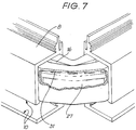
- the base (9) as shown in Figure 4 closes the bottom of the housing (8), leaving an elongated side access opening (10) which extends along the entire length of the housing (8), as shown in Figure 7. Connection to the wires therefore can be made at any position along the length of the conductive track (1).
- a take off unit in the form of a power point is shown in Figure 6.
- the power point (11) has a projection (12) extending from the back with one or more tines (13) extending radially therefrom.
- a view of the projection is shown in Figure 5.
- the tines (13) are aligned with the opening (10) and the projection (12) inserted into the opening (10) and the power point (11) rotated such that the tines (13) engage the respective blades (5) in the recesses (3). Because of the double blade spring construction, the blades (5) are urged into intimate engagement with each side of the tines (13) such that both flat areas (14), provide a relatively large contact area.
- the walls (23) of the housing (8) have their free ends (25) configured to mate with recesses (24) on the projection (12), isolating each tine (13) from the others.
- part of the length of one or more of the tines (13) can be sheathed in plastics, with or without the recesses (24), such that upon insertion of the tine into the recess (3), the plastics sheath (26) extends into the recess (3) to inhibit any arcing or discharging between the tines (13).
- the powerpoint (11), as shown in Figure 6, comprises a combined locking means and an on/off switch (15) to secure the powerpoint to the housing (8), wherein when said power point (11) is rotated, after the insertion of the tines (13) into the opening (10), power is only available to the external output (72) upon manual operation of the locking means (15).
- the projection 12 may be moulded directly to a power lead.
- a cover strip could be used to seal the opening (10).
- the housing can comprise two channels one for telecommunication and one for power.
- any number of channels could be used, for example one respectively for power, stereo systems, computer lines, gas, optical fibres, etc.
- the flexible conductive strip can be of any suitable configuration and have any number of recesses.
- a conductor (30) may be connected to the arcuate end of the connector blades (29).
- the conductor (30) could be standard copper wiring while the blade (29) could be formed of phosphorous bronze.
- the conductive blade (29) could be constructed so as to be used on its own, without the necessity of the additional conductor in the form of a copper wire (30).
- cutouts (31) are located along its length. These cutouts (31) do not extend into the contact area (32) of the arms (33) of the conductive blade. These cutouts (31) enhance the flexibility of the conductive blades (29) and hence the flexible conductive tracks (27) into which they are inserted.
- the housing (34) used to contain the flexible insulative track (35) can have external fittings (36) for the affixing of suitable colour strips (not shown).
- FIG. 13 One embodiment of a floor mounted system according to the present invention is shown in Figure 13 comprises an open face housing (37), with two opposed side walls (38) and (39), and a channel portion (40), which has a base support (41). This embodiment is used to be inserted into a recess (42) in a floor (43) as shown in Figure 14.
- cutouts (44) Located on the sides and base of the channel portion (40) are cutouts (44) to allow any moisture to drain out of the housing, and along and out of the floor recess (42).
- a mounting means (45) is provided to hold an elongated cassette (46) therein.
- the mounting means (45) comprises two parallel projections, one (47) with a hook (48) located along the free end thereof.
- the cassette (46) comprises an elongated recess (49), and a cutout (50) located at one end.
- the projection (51) is fitted into the recess (49) of the cassette (46) and the hook (48), because of the resilience of the material of the housing (37) snaps into the cutout (50), locking the cassette (46) in position.
- the cassette (46) has its open mouth (52) facing downwardly.
- a cover strip (53) can be inserted into the opening (54) below the cassette (46), where it rests on the elongated support (55) and locks into the cassette (46) by means of the projection (56) to close the mouth (52) of the cassette (46).
- Fitted into the cassette (46) can be any form of conductive track, (however preferably a flexible conductive track (1) shown in Figures 1 to 11 is used), as shown in Figure 14, with the shoulders (57) of the cassette locking over the outer walls (58) of the flexible conductive track (1), with the barbed projection (59) engaging in the locating recess (16) of the flexible track (27).
- a take off means (60) as described previously can be used to connect to the conductors (20), whereby power or the like is supplied external of the recess (42) as shown in Figure 14.
- a cover (61) rests on the top supports (62) and (63) of the housing (37), aligning flush with the flooring as shown in Figure 14.
- the cover (61) has cutouts (64) located at appropriate positions along the cover (61) to allow for egress of suitable cable. These cutouts could be preformed or cutout when needed, and a cord cover strip (65) fits into the channel (66).
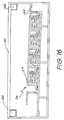
- FIG 16 the housing 34 as illustrated in Figure 12 can be used in a floor mounted arrangement similar to Figures 14 and 15.
- the housing and cassettes are made from suitable plastics.
- the cassette in use can also face sideways with a suitable hinged or flapped cover slip covering its mouth to prevent ingress of contaminants.
- the electrical connector (67) of the power point adaptor (68) comprises two arms (69) which are made of resilient metal.
- the prong (70) of an appliance (not shown) slides into engagement between the arms (69) and the screw (71) is tightened to urge the arms (69) into intimate contact with the prong (70).
- Sufficient pressure can be generated by the screw (71) to provide the equivalent of a fixed contact between the prong (70) and the arms (69).
- the prong could have a recess or bore into which the screw will engage to rigidly connect the prong to the electrical connectors.
- connection is not only limited to distribution systems, as before described, but can also be used with respect to standard power points and double adaptor connections.
Landscapes
- Connector Housings Or Holding Contact Members (AREA)
- Parts Printed On Printed Circuit Boards (AREA)
- Shielding Devices Or Components To Electric Or Magnetic Fields (AREA)
- Conductive Materials (AREA)
- Insulated Conductors (AREA)
- Structure Of Printed Boards (AREA)
- Toys (AREA)
- Coupling Device And Connection With Printed Circuit (AREA)
- Measurement And Recording Of Electrical Phenomena And Electrical Characteristics Of The Living Body (AREA)
- Elimination Of Static Electricity (AREA)
Abstract
Description
- The present invention relates to a flexible conductive track for electrical or communication or other signals connection and, more particularly, for such tracks for installation around a room or office and accessible for connection at almost any position along its length for take off of electrical, communication, or other signals.
- Prior art flexible electric conduit tracks are known. However, they all suffer from disadvantages which have prevented them from being commercially viable.
- Such a prior art is US Patent 2,062,752 - Kindberg which has wires forming the power lines embedded in two slits in a rubber housing. This results in only a small area of contact - nominally a "point contact" - between the tines of a power take off device and the conductors of the track with resultant problems with connection failure. Further the configuration of the housing does not readily allow for bending of the track in a lateral direction with respect to the slots. It being necessary to cut one or more notches to facilitate the bending of the track around a corner.
- US Patent 2,105,833 - Feuer, et al shows a track which comprises a flexible moulding having two slits with a wire embedded in each slit. Again only a "point contact" with a tine of a power take off device would occur. Further the moulding does not appear to be able to bend laterally to the slits.
- US Patent 2, 175,245 - Brockman whilst showing a flexible track, requires that the contacts are in the form of separate jaws, and also only shows a shape of housing which does not permit bending of the track laterally, but only allows bending with the ingress to the contacts being internal or external to the bend direction.
- In US Patent 2,240,180 - Frank this describes a flexible track. But does not show a track which can bend laterally. Further the contacts have individual jaws to assist bending with the ingress to the contacts being internal or external to the bend direction.
- In International Patent Application No. PCT/SE86/00579 there is described a flexible conductor strip having an elongated wire conductor surrounded by a thin insulation layer with an elongated slot extending through the insulation layer to provide access to the conductor. This conductor strip only provides a small area of contact between the conductor and a take off device. Further, because of the small diameter of the conductor strip, the strip will twist during bending resulting in the slot twisting out of position.
- Systems utilizing the above tracks as described in the abovementioned references do not allow a secure connection to the conductors in the track; but rely on a straight "push in" of the tines of the power take off into the slits containing the contacts, generally relying upon the resilience of the material of the house to retain engagement.
- A rigid supply rail system having bus bars located in vertically extending elongated channels are known, and described in International Patent Application PCT/AU86/00252. This reference provides a single small diameter elongate conductor located adjacent to the roof of the channels. Access of the channels is by way of an elongated opening located on the side wall adjacent the base of the rail. Thus the connection of the take off device is dependent on the small area of contact between the tine of the take off device and the elongated conductor. Further, when a change of direction is required for the supply rail, a corner adaptor is required to be conected between the adjacent supply rails. Therefore because of the conections between straight rail sections and corner adaptors, an increase in impedence of the supply rail system occurs. Therefore if a high fidelity signal is required, this system could cause interference or noise, distorting the signal.
- The use of a rigid supply rail is also shown in US Patents 4,243,284 - Humphreys, 4,462,650 - Humphreys and 4,479,687 - Humphreys et al. These references show a limited access to the conductors by way of discrete doorways with resultant complex arrangements for opening and closing.
- The present invention seeks to ameliorate the beforementioned disadvantages by providing a flexible distributor and assembly to bend laterally.
- According to a first aspect of the present invention there is provided an electrical distributor assembly as claimed in
claim 1. - According to a second aspect of the present invention there is provided an electrical distribution system as claimed in claim 9.
- Further features of the present invention are defined in the other appended claims.
- It is thus possible to provide an electrical distributor assembly which can be bent to accommodate corners.
- The invention will now be described by way of example with reference to the accompanying drawings in which:
- FIG. 1 illustrates an end view of a flexible conductive track according to one embodiment of the present invention;
- FIG. 2 shows an end view of a further embodiment of a flexible conductive track according to the present invention.
- FIG. 3 illustrates an end view of one embodiment of a support housing to support the conductive track of Figure 1 or 2;
- FIG. 4 illustrates a base adapted to be fitted to the housing of Figure 3;
- FIG. 5 illustrates a connection member of a take off device according to one embodiment of the present invention; and
- FIG. 5A illustrates a further form of a connection member according to another embodiment of the present invention.
- FIG. 6 illustrates a take off device according to one embodiment of the present invention.
- FIG. 7 illustrates one embodiment of the supply system according to the present invention (with the corner adapter removed) and cutaway on the flexible track.
- FIG. 8 shows a plan view of the system illustrated in Figure 7 to show the resultant configuration of one embodiment of the flexible track of the present invention during bending of the track;
- FIG. 9 shows the section view taken in the direction of arrows 9-9 in Figure 8;
- FIG. 10 shows a section view taken in the direction of arrows 10-10 in Figure 8;
- FIG. 11 illustrates another embodiment of the flexible track of the present invention;
- FIG. 12 illustrates another embodiment of the tracking system according to the present invention;
- FIG. 13 illustrates a housing according to a further embodiment of the present invention;
- FIG. 14 illustrates a distribution system of one embodiment of the present invention utilizing the housing shown in Figure 13;
- FIG. 15 illustrates a further embodiment of a housing usable in the present invention;
- FIG. 16 illustrates a further embodiment of a housing usable in the present invention;
- FIG. 17 illustrates an adaptor plug usable with the distribution systems of the present invention; and
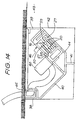
- FIG. 18 shows a cutaway view of the adaptor plug illustrated in Figure 16, showing the engagement of the connecting prong forming an electrical contact with an adaptor plug.
-
- As shown in Figure 1 a flexible conductive track (1), according to one embodiment of the present invention, comprises a flexible insulative plastics housing (2) of constant cross-section. This housing is substantially rectangular in shape with three recesses (3) open to one side of the housing.
- A conductor (4) in the form of a copper wire is held in the bottom of each recess. Affixed to the wire (4) along the whole length of the wire is a conductive blade (5) which is conductively bonded to the wire (4) to form a double spring blade contact (5). In the flexible conductive track, as shown in Figure 1, the wire (4) is held in the recesses by shoulders (6) located adjacent the bottom of each recess (3).
- The blade means can be a single blade with biasing means formed integrally with the walls of the recess to urge the tines of a take off unit into intimate contact with the blade (5). Further, the wire (4) and conductive blade (5) can be moulded into the housing wall by means of cross-head extrusion, when the housing is extruded.
- As shown in Figure 2 a further embodiment of the flexible conductive track of the present invention comprises three recesses (3) with an elongated conductors (17) connected by pressure welding to arm (18) or (19), or both, of a bifurcated contact spring (20), which extends longitudinally along the length of the recesses (3). The contact spring (20) is held in the recess (3) by the free ends (21) of contact spring (20) resiliently bearing on shoulders (22) of the recesses (3) or held in the recess by crosshead extrusion. The contact spring (20) may provide both the spring action and conductivity in the single form.
- Both flexible tracks (1), as shown in Figures 1 and 2, have a recess (16) located on the face opposite to the first face. This extends along the length of the track and enhances the flexibility of the track.
- A suitable housing (8), as shown in Figure 3, can be affixed to the wall of an area, where the system of the present invention is to be used. A single continuous length of a flexible conductive track (1), as illustrated in Figures 1 or 2, for example, is fitted into the channel (7) of the housing (8). The channel (7) is configured to hold the conductive track (1) such that open ends of the recesses (3) face downwardly.
- The base (9) as shown in Figure 4 closes the bottom of the housing (8), leaving an elongated side access opening (10) which extends along the entire length of the housing (8), as shown in Figure 7. Connection to the wires therefore can be made at any position along the length of the conductive track (1).
- When the flexible track (1) is laterally bent around a corner as shown in Figures 7, 8, 9 and 10, the recesses (16 and 3) collapse to allow lateral bending.
- A take off unit in the form of a power point is shown in Figure 6. The power point (11) has a projection (12) extending from the back with one or more tines (13) extending radially therefrom. A view of the projection is shown in Figure 5. To connect the power point (11) to the conductive strip (1), the tines (13) are aligned with the opening (10) and the projection (12) inserted into the opening (10) and the power point (11) rotated such that the tines (13) engage the respective blades (5) in the recesses (3). Because of the double blade spring construction, the blades (5) are urged into intimate engagement with each side of the tines (13) such that both flat areas (14), provide a relatively large contact area.
- To further inhibit arcing between adjacent tines (13), when connected to the conductors/blades (5) in the flexible conductive track (1), the walls (23) of the housing (8) have their free ends (25) configured to mate with recesses (24) on the projection (12), isolating each tine (13) from the others.
- Alternatively as shown in Figure 5A, part of the length of one or more of the tines (13) can be sheathed in plastics, with or without the recesses (24), such that upon insertion of the tine into the recess (3), the plastics sheath (26) extends into the recess (3) to inhibit any arcing or discharging between the tines (13).
- The powerpoint (11), as shown in Figure 6, comprises a combined locking means and an on/off switch (15) to secure the powerpoint to the housing (8), wherein when said power point (11) is rotated, after the insertion of the tines (13) into the opening (10), power is only available to the external output (72) upon manual operation of the locking means (15).
- In another embodiment the
projection 12 may be moulded directly to a power lead. - If required a cover strip could be used to seal the opening (10).
- As shown in Figure 3, the housing can comprise two channels one for telecommunication and one for power. However any number of channels could be used, for example one respectively for power, stereo systems, computer lines, gas, optical fibres, etc.
- The flexible conductive strip can be of any suitable configuration and have any number of recesses.
- To assist in the lateral bending of the flexible track an embodiment as shown in Figure 11 can be used.
- In the flexible insulative housing (27) are located three recesses (28) similar to those described previously which each contain a conductive blade (29) as shown in Figure 11. A conductor (30) may be connected to the arcuate end of the connector blades (29). The conductor (30) could be standard copper wiring while the blade (29) could be formed of phosphorous bronze. Alternatively, the conductive blade (29) could be constructed so as to be used on its own, without the necessity of the additional conductor in the form of a copper wire (30).
- At preselected positions along the length of the conductive blade (29), cutouts (31) are located along its length. These cutouts (31) do not extend into the contact area (32) of the arms (33) of the conductive blade. These cutouts (31) enhance the flexibility of the conductive blades (29) and hence the flexible conductive tracks (27) into which they are inserted.
- Additional as shown in Figure 12, the housing (34) used to contain the flexible insulative track (35) can have external fittings (36) for the affixing of suitable colour strips (not shown).
- One embodiment of a floor mounted system according to the present invention is shown in Figure 13 comprises an open face housing (37), with two opposed side walls (38) and (39), and a channel portion (40), which has a base support (41). This embodiment is used to be inserted into a recess (42) in a floor (43) as shown in Figure 14.
- Located on the sides and base of the channel portion (40) are cutouts (44) to allow any moisture to drain out of the housing, and along and out of the floor recess (42).
- A mounting means (45) is provided to hold an elongated cassette (46) therein. The mounting means (45) comprises two parallel projections, one (47) with a hook (48) located along the free end thereof.
- The cassette (46) comprises an elongated recess (49), and a cutout (50) located at one end. The projection (51) is fitted into the recess (49) of the cassette (46) and the hook (48), because of the resilience of the material of the housing (37) snaps into the cutout (50), locking the cassette (46) in position. In the embodiment shown, the cassette (46) has its open mouth (52) facing downwardly. A cover strip (53) can be inserted into the opening (54) below the cassette (46), where it rests on the elongated support (55) and locks into the cassette (46) by means of the projection (56) to close the mouth (52) of the cassette (46).
- Fitted into the cassette (46) can be any form of conductive track, (however preferably a flexible conductive track (1) shown in Figures 1 to 11 is used), as shown in Figure 14, with the shoulders (57) of the cassette locking over the outer walls (58) of the flexible conductive track (1), with the barbed projection (59) engaging in the locating recess (16) of the flexible track (27).
- A take off means (60) as described previously can be used to connect to the conductors (20), whereby power or the like is supplied external of the recess (42) as shown in Figure 14. To close the recess a cover (61) rests on the top supports (62) and (63) of the housing (37), aligning flush with the flooring as shown in Figure 14. The cover (61) has cutouts (64) located at appropriate positions along the cover (61) to allow for egress of suitable cable. These cutouts could be preformed or cutout when needed, and a cord cover strip (65) fits into the channel (66).
- Other embodiments of the present invention are shown in Figure 15 utilising multiple cassette mountings (45).
- In Figure 16 the
housing 34 as illustrated in Figure 12 can be used in a floor mounted arrangement similar to Figures 14 and 15. - Preferably the housing and cassettes are made from suitable plastics.
- The cassette in use can also face sideways with a suitable hinged or flapped cover slip covering its mouth to prevent ingress of contaminants.
- As is shown in Figures 17 and 18, the electrical connector (67) of the power point adaptor (68) comprises two arms (69) which are made of resilient metal. The prong (70) of an appliance (not shown) slides into engagement between the arms (69) and the screw (71) is tightened to urge the arms (69) into intimate contact with the prong (70). Sufficient pressure can be generated by the screw (71) to provide the equivalent of a fixed contact between the prong (70) and the arms (69).
- In a further embodiment not shown, the prong could have a recess or bore into which the screw will engage to rigidly connect the prong to the electrical connectors.
- This form of connection is not only limited to distribution systems, as before described, but can also be used with respect to standard power points and double adaptor connections.
Claims (13)
- An electrical distributor assembly including:-a longitudinally extending elongate flexible insulated housing (2) having two opposed faces,and at least two elongate flexible conductors (4, 5);
characterised in that:said insulated housing (2) has a plurality of longitudinally extending slots (3) opening inwardly from one said face thereof and at least one longitudinally extending slot (16) opening inwardly from said opposite face thereof;a conductor (4, 5) is located in at least two of the slots in said one face; andthe arrangement is such that the said slots collapse to allow lateral bending of the electrical distributor assembly. - An electrical distributor assembly as claimed in claim 1, characterised in that said at least one longitudinally extending slot (16) is a first longitudinally extending slot located substantially centrally in said opposite face and said plurality of extending slots (3) includes second and third longitudinally extending slots located off-centre in said one face.
- An electrical distributor assembly as claimed in claim 2, characterised in that said plurality of extending slots (3) includes a fourth longitudinally extending slot located substantially centrally in said one face.
- An electrical distributor assembly as claimed in claim 3, characterised in that the slots in said one face include support means (6, 22) for supporting said conductor assembly.
- An electrical distributor assembly as claimed in claim 4, characterised in that said insulated housing is an extrusion.
- An electrical distributor assembly as claimed in any one of the preceding claims, characterised in that said conductor includes a flexible elongate conductor (4) and a flexible elongate blade member (5) in electrical contact with said conductor and adapted to closely receive a tine (12) of a plug assembly (11) and establish electrical contact herewith.
- An electrical distributor assembly as claimed in claim 6, characterised in that said elongate blade member is substantially U-shaped in cross-section and has a pair of opposed and inwardly biased substantially arcuate arms, the closed portion of said blade member housing said conductor.
- An electrical distributor assembly as claimed in claim 7, characterised in that said elongate blade member has a plurality of spaced cut-outs (31) located along said closed portion.
- An electrical distribution system including:-a support housing (8, 34) having at least one longitudinally extending chamber;an electrical distributor assembly located in said chamber, andat least one plug assembly (11) having a plurality of tines (13) for establishing electrical contact with said electrical distributor assembly;
characterised in thatsaid electrical distributor assembly is an assembly as claimed in any one of the preceding claims and is located in said chamber and spaced from a wall of said chamber to define a substantially continuous longitudinally extending access channel therewith,the arrangement being such that following the insertion of said plug assembly tines (13) received within said access channel, said plug assembly tines are rotatable within said access channel to cause the tines to engage the conductors establish electrical contact. - An electrical distribution system as claimed in claim 9, characterised in that said plug assembly is adapted to abut said support housing and includes a projecting member (12) receivable within said access channel when said plug assembly abuts said support housing, said tines (13) extending radially from said projecting member.
- An electrical distribution system as claimed in claim 9, characterised in that said chamber includes an engagement member (59) adapted to be lockingly engaged in said first slot for supporting said insulated housing.
- An electrical distribution system as claimed in claim 11, characterised in that said chamber includes rib or shoulder means for supporting said insulated housing.
- An electrical distribution system as claimed in claim 12, characterised in that said plug assembly includes recess means (24) between said tines (13) for closely receiving an edge (25) of a wall member (23) formed between adjacent slots in said one face.
Applications Claiming Priority (13)
| Application Number | Priority Date | Filing Date | Title |
|---|---|---|---|
| AU7592 | 1991-08-05 | ||
| AU75/92 | 1991-08-05 | ||
| AUPK759291 | 1991-08-05 | ||
| AU13991 | 1991-12-20 | ||
| AU139/91 | 1991-12-20 | ||
| AUPL013991 | 1991-12-20 | ||
| AUPL081692 | 1992-02-11 | ||
| AU816/92 | 1992-02-11 | ||
| AU81692 | 1992-02-11 | ||
| AUPL331192 | 1992-07-02 | ||
| AU331192 | 1992-07-02 | ||
| AU3311/92 | 1992-07-02 | ||
| PCT/AU1992/000414 WO1993003517A1 (en) | 1991-08-05 | 1992-08-05 | Flexible conductive track |
Publications (3)
| Publication Number | Publication Date |
|---|---|
| EP0597980A1 EP0597980A1 (en) | 1994-05-25 |
| EP0597980A4 EP0597980A4 (en) | 1996-05-08 |
| EP0597980B1 true EP0597980B1 (en) | 2000-04-26 |
Family
ID=27424314
Family Applications (1)
| Application Number | Title | Priority Date | Filing Date |
|---|---|---|---|
| EP92916988A Expired - Lifetime EP0597980B1 (en) | 1991-08-05 | 1992-08-05 | Flexible conductive track |
Country Status (11)
| Country | Link |
|---|---|
| EP (1) | EP0597980B1 (en) |
| JP (1) | JP3198293B2 (en) |
| KR (1) | KR100247102B1 (en) |
| AT (1) | ATE192268T1 (en) |
| BR (1) | BR9206402A (en) |
| CA (1) | CA2114617C (en) |
| DE (1) | DE69230971T2 (en) |
| FI (1) | FI940518A (en) |
| HU (1) | HUT67892A (en) |
| SG (1) | SG43100A1 (en) |
| WO (1) | WO1993003517A1 (en) |
Families Citing this family (13)
| Publication number | Priority date | Publication date | Assignee | Title |
|---|---|---|---|---|
| WO1995003644A1 (en) * | 1993-07-20 | 1995-02-02 | Mass International Pty. Ltd. | Electrical distribution system |
| DK0787373T3 (en) | 1994-10-14 | 2002-04-08 | John Ashton Sinclair | Flexible electric conductor |
| DE19510507C2 (en) * | 1995-03-23 | 1999-11-18 | Alulite Lichtsysteme Gmbh | Electric lighting system |
| AUPO222996A0 (en) * | 1996-09-10 | 1996-10-03 | Universal Power Track Pty Ltd | An electrical supply assembly |
| DE29723006U1 (en) * | 1997-12-31 | 1998-02-26 | Josef Soelken Gmbh & Co Kg | Track system |
| DE29821304U1 (en) * | 1998-11-28 | 2000-04-13 | Giersiepen Gira Gmbh | Busbar, especially baseboard |
| AUPQ187599A0 (en) * | 1999-07-28 | 1999-08-19 | Universal Power Track Pty Ltd | An electric supply assembly |
| DE10018074A1 (en) * | 2000-03-31 | 2001-10-04 | Briloner Leuchten Gmbh | Lighting device has one or more light units that can be mounted on bus bar system, one or more camera elements that can be mounted on or in separate component from light unit |
| AU2002953429A0 (en) | 2002-12-18 | 2003-01-09 | Power And Communications Logistics Pty Limited | An elongate electrical conductor that is adapted for electrically connecting with an electrical contact |
| USRE45456E1 (en) | 2002-12-18 | 2015-04-07 | Power & Data Corporation Pty Ltd. | Elongated electrical conductor that is adapted for electrically connecting with an electrical contact |
| GB2414869A (en) * | 2003-08-18 | 2005-12-07 | John Ashton Sinclair | Electrical plug and busbar system |
| DE102019126955A1 (en) * | 2019-10-08 | 2021-04-08 | Zumtobel Lighting Gmbh | Support rail for lights or electrical units |
| IT202000006409A1 (en) * | 2020-03-26 | 2021-09-26 | Ellamp S P A | ELECTRICAL MANAGEMENT SYSTEM OF SERVICES ON BOARD OF A VEHICLE OF PUBLIC TRANSPORT VIA CONDUCTIVE TRACKS |
Family Cites Families (10)
| Publication number | Priority date | Publication date | Assignee | Title |
|---|---|---|---|---|
| GB394199A (en) * | 1932-10-12 | 1933-06-22 | Aldo Franco Pessina | Improvements in electric lines |
| US2175245A (en) * | 1937-07-19 | 1939-10-10 | James R Brockman | Electric socket |
| US2243990A (en) * | 1938-08-06 | 1941-06-03 | Thora | Electric outlet conduit |
| US2478006A (en) * | 1946-12-10 | 1949-08-02 | James J Paden | Continuous electrical receptacle |
| NL155136B (en) * | 1972-03-18 | 1977-11-15 | Philips Nv | POWER TAKE-OFF RAIL FOR MOVABLE POWER TAKE-OFF DEVICES. |
| JPS5257989A (en) * | 1975-11-06 | 1977-05-12 | Sharp Corp | Connection of flexible distributing board |
| NL7810941A (en) * | 1978-11-03 | 1980-05-07 | Philips Nv | COMBINATION OF CURRENT TAKER AND VOLTAGE RAIL, AND PART OF THIS COMBINATION. |
| GB2087168B (en) * | 1980-10-28 | 1985-01-30 | Electrak Int Ltd | Electrical distribution system |
| AU6286686A (en) * | 1985-09-05 | 1987-03-24 | Barrier Shelf Co. (No. 27) Pty. Ltd. | Electrical supply rail system |
| FR2642911B1 (en) * | 1989-02-07 | 1993-11-05 | Legrand | PROFILE, SUCH AS CHUTE, PLINTH, MOLDING OR THE LIKE, FOR HOUSING AND PROTECTION, IN PARTICULAR, OF ELECTRICAL EQUIPMENT AND CONDUCTORS NECESSARY TO THE SERVING THEREOF |
-
1992
- 1992-08-05 HU HU9400297A patent/HUT67892A/en unknown
- 1992-08-05 EP EP92916988A patent/EP0597980B1/en not_active Expired - Lifetime
- 1992-08-05 SG SG1996003640A patent/SG43100A1/en unknown
- 1992-08-05 WO PCT/AU1992/000414 patent/WO1993003517A1/en active IP Right Grant
- 1992-08-05 DE DE69230971T patent/DE69230971T2/en not_active Expired - Fee Related
- 1992-08-05 KR KR1019940700315A patent/KR100247102B1/en not_active IP Right Cessation
- 1992-08-05 CA CA002114617A patent/CA2114617C/en not_active Expired - Fee Related
- 1992-08-05 BR BR9206402A patent/BR9206402A/en not_active IP Right Cessation
- 1992-08-05 JP JP50312093A patent/JP3198293B2/en not_active Expired - Fee Related
- 1992-08-05 AT AT92916988T patent/ATE192268T1/en not_active IP Right Cessation
-
1994
- 1994-02-04 FI FI940518A patent/FI940518A/en unknown
Also Published As
| Publication number | Publication date |
|---|---|
| DE69230971D1 (en) | 2000-05-31 |
| WO1993003517A1 (en) | 1993-02-18 |
| EP0597980A4 (en) | 1996-05-08 |
| HU9400297D0 (en) | 1994-05-30 |
| KR100247102B1 (en) | 2000-03-15 |
| BR9206402A (en) | 1995-03-01 |
| JP3198293B2 (en) | 2001-08-13 |
| HUT67892A (en) | 1995-05-29 |
| FI940518A (en) | 1994-03-10 |
| EP0597980A1 (en) | 1994-05-25 |
| ATE192268T1 (en) | 2000-05-15 |
| CA2114617C (en) | 1997-06-24 |
| CA2114617A1 (en) | 1993-02-18 |
| DE69230971T2 (en) | 2000-12-07 |
| JPH06511345A (en) | 1994-12-15 |
| FI940518A0 (en) | 1994-02-04 |
| SG43100A1 (en) | 1997-10-17 |
Similar Documents
| Publication | Publication Date | Title |
|---|---|---|
| US5618192A (en) | Flexible conductive track | |
| EP0920716B1 (en) | Electrical wiring system | |
| US4884981A (en) | Shielded data connector | |
| US5860829A (en) | Cross connect terminal block | |
| US5855493A (en) | Electrical connector strain relief with shield ground for multiple cables | |
| EP0597980B1 (en) | Flexible conductive track | |
| US6795320B2 (en) | Method and apparatus for supplying data and power to panel-supported components | |
| US4223971A (en) | Electrical wiring assembly and method | |
| EP0106535A2 (en) | Electrical track | |
| US4066320A (en) | Electrical conductor terminating system | |
| JPS62262381A (en) | Shielded cable assembly | |
| US4487997A (en) | Electric cable | |
| KR100492804B1 (en) | An elongated flexible electric conductor | |
| AU2007349106B2 (en) | Electric connector with a dust cover | |
| US6805567B2 (en) | Power distribution system | |
| US4437725A (en) | Junction connections for modular wiring systems | |
| AU655069B2 (en) | Flexible conductive track | |
| US6007367A (en) | Apparatus for connecting cable cores | |
| US5470250A (en) | Bridging terminal block | |
| US4968267A (en) | Programmable microcontroller microbus connector arrangement | |
| RU2107372C1 (en) | Flexible switchgear busbar | |
| US5897383A (en) | Cross-connect bus | |
| US6191358B1 (en) | Building entrance box with localized wire potting | |
| EP0744092B1 (en) | Electrical distribution system | |
| US20230396002A1 (en) | Terminal block bus structure and bus module thereof |
Legal Events
| Date | Code | Title | Description |
|---|---|---|---|
| PUAI | Public reference made under article 153(3) epc to a published international application that has entered the european phase |
Free format text: ORIGINAL CODE: 0009012 |
|
| 17P | Request for examination filed |
Effective date: 19940221 |
|
| AK | Designated contracting states |
Kind code of ref document: A1 Designated state(s): AT BE CH DE DK ES FR GB GR IE IT LI LU MC NL SE |
|
| A4 | Supplementary search report drawn up and despatched |
Effective date: 19960321 |
|
| AK | Designated contracting states |
Kind code of ref document: A4 Designated state(s): AT BE CH DE DK ES FR GB GR IE IT LI LU MC NL SE |
|
| 17Q | First examination report despatched |
Effective date: 19971125 |
|
| GRAG | Despatch of communication of intention to grant |
Free format text: ORIGINAL CODE: EPIDOS AGRA |
|
| GRAG | Despatch of communication of intention to grant |
Free format text: ORIGINAL CODE: EPIDOS AGRA |
|
| GRAG | Despatch of communication of intention to grant |
Free format text: ORIGINAL CODE: EPIDOS AGRA |
|
| GRAH | Despatch of communication of intention to grant a patent |
Free format text: ORIGINAL CODE: EPIDOS IGRA |
|
| GRAH | Despatch of communication of intention to grant a patent |
Free format text: ORIGINAL CODE: EPIDOS IGRA |
|
| GRAA | (expected) grant |
Free format text: ORIGINAL CODE: 0009210 |
|
| AK | Designated contracting states |
Kind code of ref document: B1 Designated state(s): AT BE CH DE DK ES FR GB GR IE IT LI LU MC NL SE |
|
| PG25 | Lapsed in a contracting state [announced via postgrant information from national office to epo] |
Ref country code: NL Free format text: LAPSE BECAUSE OF FAILURE TO SUBMIT A TRANSLATION OF THE DESCRIPTION OR TO PAY THE FEE WITHIN THE PRESCRIBED TIME-LIMIT Effective date: 20000426 Ref country code: LI Free format text: LAPSE BECAUSE OF FAILURE TO SUBMIT A TRANSLATION OF THE DESCRIPTION OR TO PAY THE FEE WITHIN THE PRESCRIBED TIME-LIMIT Effective date: 20000426 Ref country code: GR Free format text: LAPSE BECAUSE OF NON-PAYMENT OF DUE FEES Effective date: 20000426 Ref country code: ES Free format text: THE PATENT HAS BEEN ANNULLED BY A DECISION OF A NATIONAL AUTHORITY Effective date: 20000426 Ref country code: CH Free format text: LAPSE BECAUSE OF FAILURE TO SUBMIT A TRANSLATION OF THE DESCRIPTION OR TO PAY THE FEE WITHIN THE PRESCRIBED TIME-LIMIT Effective date: 20000426 Ref country code: BE Free format text: LAPSE BECAUSE OF FAILURE TO SUBMIT A TRANSLATION OF THE DESCRIPTION OR TO PAY THE FEE WITHIN THE PRESCRIBED TIME-LIMIT Effective date: 20000426 Ref country code: AT Free format text: LAPSE BECAUSE OF FAILURE TO SUBMIT A TRANSLATION OF THE DESCRIPTION OR TO PAY THE FEE WITHIN THE PRESCRIBED TIME-LIMIT Effective date: 20000426 |
|
| REF | Corresponds to: |
Ref document number: 192268 Country of ref document: AT Date of ref document: 20000515 Kind code of ref document: T |
|
| REG | Reference to a national code |
Ref country code: CH Ref legal event code: EP |
|
| REF | Corresponds to: |
Ref document number: 69230971 Country of ref document: DE Date of ref document: 20000531 |
|
| REG | Reference to a national code |
Ref country code: IE Ref legal event code: FG4D |
|
| ITF | It: translation for a ep patent filed |
Owner name: OBEROSLER LUDWIG |
|
| PG25 | Lapsed in a contracting state [announced via postgrant information from national office to epo] |
Ref country code: SE Free format text: LAPSE BECAUSE OF FAILURE TO SUBMIT A TRANSLATION OF THE DESCRIPTION OR TO PAY THE FEE WITHIN THE PRESCRIBED TIME-LIMIT Effective date: 20000726 Ref country code: DK Free format text: LAPSE BECAUSE OF FAILURE TO SUBMIT A TRANSLATION OF THE DESCRIPTION OR TO PAY THE FEE WITHIN THE PRESCRIBED TIME-LIMIT Effective date: 20000726 |
|
| PG25 | Lapsed in a contracting state [announced via postgrant information from national office to epo] |
Ref country code: LU Free format text: LAPSE BECAUSE OF NON-PAYMENT OF DUE FEES Effective date: 20000805 |
|
| PG25 | Lapsed in a contracting state [announced via postgrant information from national office to epo] |
Ref country code: IE Free format text: LAPSE BECAUSE OF NON-PAYMENT OF DUE FEES Effective date: 20000807 |
|
| ET | Fr: translation filed | ||
| PG25 | Lapsed in a contracting state [announced via postgrant information from national office to epo] |
Ref country code: MC Free format text: THE PATENT HAS BEEN ANNULLED BY A DECISION OF A NATIONAL AUTHORITY Effective date: 20000831 |
|
| NLV1 | Nl: lapsed or annulled due to failure to fulfill the requirements of art. 29p and 29m of the patents act | ||
| REG | Reference to a national code |
Ref country code: CH Ref legal event code: PL |
|
| PLBE | No opposition filed within time limit |
Free format text: ORIGINAL CODE: 0009261 |
|
| STAA | Information on the status of an ep patent application or granted ep patent |
Free format text: STATUS: NO OPPOSITION FILED WITHIN TIME LIMIT |
|
| 26N | No opposition filed | ||
| REG | Reference to a national code |
Ref country code: IE Ref legal event code: MM4A |
|
| REG | Reference to a national code |
Ref country code: GB Ref legal event code: IF02 |
|
| PGFP | Annual fee paid to national office [announced via postgrant information from national office to epo] |
Ref country code: GB Payment date: 20050204 Year of fee payment: 13 |
|
| PGFP | Annual fee paid to national office [announced via postgrant information from national office to epo] |
Ref country code: DE Payment date: 20050222 Year of fee payment: 13 |
|
| PGFP | Annual fee paid to national office [announced via postgrant information from national office to epo] |
Ref country code: FR Payment date: 20050223 Year of fee payment: 13 |
|
| PG25 | Lapsed in a contracting state [announced via postgrant information from national office to epo] |
Ref country code: IT Free format text: LAPSE BECAUSE OF NON-PAYMENT OF DUE FEES;WARNING: LAPSES OF ITALIAN PATENTS WITH EFFECTIVE DATE BEFORE 2007 MAY HAVE OCCURRED AT ANY TIME BEFORE 2007. THE CORRECT EFFECTIVE DATE MAY BE DIFFERENT FROM THE ONE RECORDED. Effective date: 20050805 Ref country code: GB Free format text: LAPSE BECAUSE OF NON-PAYMENT OF DUE FEES Effective date: 20050805 |
|
| PG25 | Lapsed in a contracting state [announced via postgrant information from national office to epo] |
Ref country code: DE Free format text: LAPSE BECAUSE OF NON-PAYMENT OF DUE FEES Effective date: 20060301 |
|
| GBPC | Gb: european patent ceased through non-payment of renewal fee |
Effective date: 20050805 |
|
| PG25 | Lapsed in a contracting state [announced via postgrant information from national office to epo] |
Ref country code: FR Free format text: LAPSE BECAUSE OF NON-PAYMENT OF DUE FEES Effective date: 20060428 |
|
| REG | Reference to a national code |
Ref country code: FR Ref legal event code: ST Effective date: 20060428 |