EP0597487A2 - Asynchronous transfer mode communication system - Google Patents
Asynchronous transfer mode communication system Download PDFInfo
- Publication number
- EP0597487A2 EP0597487A2 EP93118360A EP93118360A EP0597487A2 EP 0597487 A2 EP0597487 A2 EP 0597487A2 EP 93118360 A EP93118360 A EP 93118360A EP 93118360 A EP93118360 A EP 93118360A EP 0597487 A2 EP0597487 A2 EP 0597487A2
- Authority
- EP
- European Patent Office
- Prior art keywords
- vci
- communication system
- routing
- address
- cell
- Prior art date
- Legal status (The legal status is an assumption and is not a legal conclusion. Google has not performed a legal analysis and makes no representation as to the accuracy of the status listed.)
- Withdrawn
Links
Images


Classifications
-
- H—ELECTRICITY
- H04—ELECTRIC COMMUNICATION TECHNIQUE
- H04L—TRANSMISSION OF DIGITAL INFORMATION, e.g. TELEGRAPHIC COMMUNICATION
- H04L49/00—Packet switching elements
- H04L49/30—Peripheral units, e.g. input or output ports
- H04L49/3081—ATM peripheral units, e.g. policing, insertion or extraction
-
- H—ELECTRICITY
- H04—ELECTRIC COMMUNICATION TECHNIQUE
- H04L—TRANSMISSION OF DIGITAL INFORMATION, e.g. TELEGRAPHIC COMMUNICATION
- H04L49/00—Packet switching elements
- H04L49/25—Routing or path finding in a switch fabric
- H04L49/253—Routing or path finding in a switch fabric using establishment or release of connections between ports
- H04L49/254—Centralised controller, i.e. arbitration or scheduling
-
- H—ELECTRICITY
- H04—ELECTRIC COMMUNICATION TECHNIQUE
- H04L—TRANSMISSION OF DIGITAL INFORMATION, e.g. TELEGRAPHIC COMMUNICATION
- H04L49/00—Packet switching elements
- H04L49/60—Software-defined switches
- H04L49/602—Multilayer or multiprotocol switching, e.g. IP switching
-
- H—ELECTRICITY
- H04—ELECTRIC COMMUNICATION TECHNIQUE
- H04Q—SELECTING
- H04Q11/00—Selecting arrangements for multiplex systems
- H04Q11/04—Selecting arrangements for multiplex systems for time-division multiplexing
- H04Q11/0428—Integrated services digital network, i.e. systems for transmission of different types of digitised signals, e.g. speech, data, telecentral, television signals
- H04Q11/0478—Provisions for broadband connections
-
- H—ELECTRICITY
- H04—ELECTRIC COMMUNICATION TECHNIQUE
- H04L—TRANSMISSION OF DIGITAL INFORMATION, e.g. TELEGRAPHIC COMMUNICATION
- H04L12/00—Data switching networks
- H04L12/54—Store-and-forward switching systems
- H04L12/56—Packet switching systems
- H04L12/5601—Transfer mode dependent, e.g. ATM
- H04L2012/5629—Admission control
- H04L2012/5631—Resource management and allocation
- H04L2012/5632—Bandwidth allocation
-
- H—ELECTRICITY
- H04—ELECTRIC COMMUNICATION TECHNIQUE
- H04L—TRANSMISSION OF DIGITAL INFORMATION, e.g. TELEGRAPHIC COMMUNICATION
- H04L12/00—Data switching networks
- H04L12/54—Store-and-forward switching systems
- H04L12/56—Packet switching systems
- H04L12/5601—Transfer mode dependent, e.g. ATM
- H04L2012/5638—Services, e.g. multimedia, GOS, QOS
- H04L2012/5665—Interaction of ATM with other protocols
- H04L2012/5667—IP over ATM
-
- H—ELECTRICITY
- H04—ELECTRIC COMMUNICATION TECHNIQUE
- H04L—TRANSMISSION OF DIGITAL INFORMATION, e.g. TELEGRAPHIC COMMUNICATION
- H04L49/00—Packet switching elements
- H04L49/30—Peripheral units, e.g. input or output ports
- H04L49/3009—Header conversion, routing tables or routing tags
-
- H—ELECTRICITY
- H04—ELECTRIC COMMUNICATION TECHNIQUE
- H04L—TRANSMISSION OF DIGITAL INFORMATION, e.g. TELEGRAPHIC COMMUNICATION
- H04L49/00—Packet switching elements
- H04L49/55—Prevention, detection or correction of errors
- H04L49/552—Prevention, detection or correction of errors by ensuring the integrity of packets received through redundant connections
Definitions
- the present invention relates generally to a setting of virtual connection (VC) in an asynchronous transfer mode (ATM) communication system. More specifically, the invention relates to a VC setting system for a local area network (LAN) communication.
- ATM asynchronous transfer mode
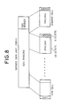
- an original information i.e. service data unit (variable length) is transmitted by dividing into fixed length cells including 5 octets of header and 48 octets of payload, as shown in Fig. 8. Routing in the ATM system is performed using a virtual connection ID (VCI) in the header.
- VCI virtual connection ID
- VC setting systems In ATM communication system, there are two VC setting systems, i.e. a method for setting the VC employing a dedicated VC for signaling setting and a permanent virtual connection (PVC) for Semi-permanently setting the VC.
- PVC permanent virtual connection
- the former method employs a similar method to call setting in an integrated service digital network (ISDN), namely, C (control)-plane and U (User)-plane are set separately and the call in U-plane communication is set by C-plane, which method is referred to as "outband signaling".
- ISDN integrated service digital network
- the later method does not employ C-plane, in which routes for all distant users are preliminarily established for selecting VC depending upon the distant user to call.
- the communication in C-plane is a communication not with the distant user but with a call control portion.
- the data amount to be handled by U-plane becomes substantially equal to the data amount to be handled by C-plane to cause large overhead resulting in increasing of delay period and degradation of through put.
- the later PVC method holds shortcoming that a routing table for defining correspondence between VCI and address information has to be preliminarily prepared upon establishing the system. Furthermore, preparation of the routing table requires complicated operation and possibly cause error.
- the present invention is to resolve the defects and drawbacks in the prior art as set forth above. Therefore, it is an object of the present invention to provide an ATM communication system which permits high speed communication and has high flexibility and expendability.
- Another object of the invention is to provide an ATM communication system which can reduce required operation in establishing the system.
- a communication system performing an asynchronous transfer mode communication employing a fixed length cell comprises:
- the communication system may further comprise:
- FIG. 1 is a block diagram showing a construction of one embodiment of an ATM communication system in accordance with the present invention.
- the shown embodiment of the ATM communication system includes an ATM switching system (ATM system) comprising a transmitting terminal 1 as a transmitting device, an ATM switch 2 and a routing controller 3, and a receiving terminal 4 as a receiver device.
- ATM system ATM switching system
- the ATM switch 2 has four ports PN1 - PN4 at an input port side (IN side) and four ports PN1 - PN4 at an output port side (OUT side).
- the ATM switch 2 is controlled by the routing controller 3 for establishing routing connection between respective inlet ports and outlet ports.
- transmitting terminals and receiving terminals are connected to respective ports of the ATM switch 2.
- a vacant VCI table 11, and a VCI-IP (internet protocol) address table 12 are provided in the transmitting terminal 1.
- VCI-IP address table 41 is provided in the receiving terminal 4.
- routing controller 3 a routing table 31 is provided in the routing controller 3. Detailed discussion will be given later.
- Fig. 5(a) is a block diagram showing an example of the internal structure of the transmitting terminal 1, in which the transmitting terminal 1 includes a buffer 15 for temporarily storing a data to be transmitted, i.e. a service data unit (SDU), a cell assembling means 14 for dividing the data stored in the buffer 15 and assembling fixed length cells.
- SDU service data unit
- the transmitting terminal 1 further includes a processor 13 for adding VCI or AD for the header portions of respective cells after assembling the cells, the vacant VCI table 11 indicating VCs currently not used, and the VCI-IP address table 12 indicating correspondence between the currently used VC and the IP address of distant user on communication.
- the service data unit stored in the buffer 15 is supplied to the cell assembling means 14 and thus divided into the fixed length cells.
- the processor 13 reads out the IP address and set an identification bit AD of the cell containing the read out IP address. Also, the processor 13 makes reference to the VCI-IP address table 12 on the basis of the read out IP address of the distant terminal to make a call.
- the corresponding VCI is written in the headers of respective cells.
- a vacant VC i.e. the VC which is not currently used, is selected from the vacant VCI table 11 to register in the VCI-IP table 12. Thereafter, the VCI is written in the headers of respective cells. Each cell is supplied to the input port of the ATM switch in order.
- FIG. 2(a) is a conceptual diagrammatic illustration showing an example of variation of the content of registration of the vacant VCI table 11 and the VCI-IP address table 12.
- Fig. 2(a) shows the vacant VCI table 11 and the VCI-IP address table 12 after modification.
- the correspondence between VCI "2" and the IP address "123" is registered.
- the VCI "2" becomes occupied state and thus eliminated from the vacant VCI table 11. Therefore, in the vacant VCI table 11, only VCI "3" is remained.
- Fig. 5(b) shows the internal structure of the receiving terminal 4.
- the receiving terminal 4 includes a cell disassembling means 44 for disassembling the cells and restoring the service data unit, a buffer 45, the VCI-IP address table 41 indicating the correspondence between the received IP address of the transmission side terminal and the VCI, and a processor 43 for performing writing process for the table 41.
- the cells supplied from the output port of the ATM switch are input to the cell disassembling means 44. Then, the payload portion of respective cells are fed to the buffer 45 in order and accumulated therein. By this, the original service data unit can be restored by interconnecting the payloads accumulated in the buffer 45.
- the processor 43 reads out the IP address from the cell and writes the correspondence between the read out IP address and the VCI in the VCI-IP address table 41 for registration.
- FIG. 2(b) is a conceptual illustration showing an example of variation of the content of registration in the VCI-IP address table 41.
- the correspondence between VCI "3" and the IP address "101", and the correspondence between VCI "2" and the IP address "211" are stored.
- new correspondence between the VCI and the IP address is registered in the VCI-I address table 41.
- the lower table in Fig. 2(b) shows addition of the correspondence between VCI "1" and the IP address "210" of the transmitting terminal 1.
- FIG. 6 is a block diagram showing the internal structure of the ATM switch 2 and the routing controller 3 in Fig. 1, in which the like reference numerals represent like elements.
- the ATM switch 2 comprises input buffers 21 and 22 provided corresponding to respective input ports, output buffers 23 and 24 provided corresponding to respective output ports and a switching circuit 20 forming connection switches between respective input and output buffers.
- the routing controller 3 includes the routing table 31 for registering correspondence between the input port and the output port of the ATM switch 2, a read/write control circuit 32 for identification of the output port and assigning VCI at the output port according to the content of registration in the routing table 31, and a processor 33 for determining the output port on the basis of the IP address of the distant terminal to be called and select the vacant VCI at the output port for registering in the routing table 31.
- the input buffer stores the data from the transmitting terminal 1 per cell. Then, the read/write control circuit 32 read out the VCI of the cell in the input buffer and performs identification of the output port and assignment of the VCI at the output port according to the content of registration in the routing table 31 - (later-mentioned path @)in Fig. 1).
- the processor 33 determines the output port on the basis of the IP address of the distant terminal to be called and select one of the vacant VCI at the output port to register as the VCI (later-mentioned paths 10 and 02 of Fig. 1).
- Fig. 2(c) shows an example of variation of the content of registration.
- the transmitting terminal 1 is provided the function for dividing the data to be transmitted, i.e. a packet frame or service data unit (SDU) into one or more ATM cells.
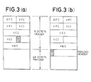
- the identification AD may be defined in 5 octets of cell header in the cell format (Fig. 3(a)), or, in the alternative, may be defined in the payload header in the 48 octets cell (Fig. 3(b)).
- GFC represents a general flow control
- VPI represents a virtual path ID
- the VCI represents the virtual connection ID
- HEC represents a header error control
- each cell assigned VCI "2" (Fig. 4(a)) is input to the input port PN2 of the ATM switch 2.
- the header portion is re-written and output to the output port PN4 as the cell assigned VCI "1 " as shown in Fig. 4(b).
- the cells thus output to the output port PN4 is transmitted to the receiving terminal 4.
- the SDU header of the service data unit contains the IP address consisted of a calling party IP address indicative of the transmitting terminal and a destination IP address indicative of the receiving terminal. Routing are determined on the basis of these addresses.
- the non-routed cells are connected to the routing controller 3 11of Fig. 1).
- the second and subsequent cells are directly transferred from the input port PN2 to the output port PN4 without passing through the routing controller 3 since the path has already been set in the routing table 31 (3of Fig. 1).
- the IP address information is set as the SDU header with not only the destination IP address, i.e. the IP address "123" of the receiving terminal 4 but also the address "210" indicating the transmitting terminal 1. Therefore, as shown in Fig. 2(b), the VCI-IP address table 41 in the receiving terminal 4 is consisted of the correspondence of the IP address of the transmitting terminal 1 and the VCI.
- the VCI-IP address table may be expanded to include correspondence between the VCI, the IP address of the calling party and the destination IP address, Also, the routing table 31 in the routing controller 3, not only the correspondence between the PN numbers of the input and output ports and the VCI, the calling party IP address and the destination IP address may be stored.
- IP address transferring cell is identified. Then, independently of data transfer, IP address pair (destination IP address and calling party IP address) is transferred for setting the VC.
- the IP address pair may be transmitted at every given interval To.
- the IP address pair may be transmitted when a period where no data is transmitted, exceeds a given period Ti.
- arrows represent IP address pair transferring cells and hatched portions represent normal data transferring period on the normal cell base.
- various methods may be employed in canceling the set VCI or for restoring the past set VCI. Namely, the VCI may be canceled per service data unit when absence of cell transmission is maintained for a predetermined period of time. On the other hand, the VCI may be restored by means of a special cell or so forth.
- the address information should not be specified to the IP address, but can be known ISDN address, MAC (media access control) address, or any other address information which can specify the terminal or host.
Landscapes
- Engineering & Computer Science (AREA)
- Computer Networks & Wireless Communication (AREA)
- Signal Processing (AREA)
- Data Exchanges In Wide-Area Networks (AREA)
- Use Of Switch Circuits For Exchanges And Methods Of Control Of Multiplex Exchanges (AREA)
Abstract
An ATM communication system is capable of minimizing delay period and achieving high through put without requiring setting of the corresponding table of the VC and the routing. The communication system includes a vacant virtual connection (VC) table indicating not used VC. The VC is retrieved in response to a transmission demand and set in an ATM cell as a virtual connection ID (VCI). Then, the cell is transmitted with adding an address information identifying destination. An ATM switch and a routing controller determine routing from a transmitting terminal to a receiving terminal. The determined routing is stored in a routing table in the routing controller. Then, through the determined routing, data is transferred from the transmitting terminal to the receiving terminal.
Description
- The present invention relates generally to a setting of virtual connection (VC) in an asynchronous transfer mode (ATM) communication system. More specifically, the invention relates to a VC setting system for a local area network (LAN) communication.
- ATM communication system employing a fixed length cell as a transfer unit has an excellent characteristics to permit uniting point-to-multipoint communication and multimedia communication. Therefore, in the recent years, the ATM communication system is attracting attention in the application for LAN communication. Here. in burst communication, an original information, i.e. service data unit (variable length) is transmitted by dividing into fixed length cells including 5 octets of header and 48 octets of payload, as shown in Fig. 8. Routing in the ATM system is performed using a virtual connection ID (VCI) in the header.
- In ATM communication system, there are two VC setting systems, i.e. a method for setting the VC employing a dedicated VC for signaling setting and a permanent virtual connection (PVC) for Semi-permanently setting the VC.
- The former method employs a similar method to call setting in an integrated service digital network (ISDN), namely, C (control)-plane and U (User)-plane are set separately and the call in U-plane communication is set by C-plane, which method is referred to as "outband signaling".
- On the other hand, the later method does not employ C-plane, in which routes for all distant users are preliminarily established for selecting VC depending upon the distant user to call.
- PVC method has been disclosed in Japanese Unexamined Patent Publications Nos. 2-234538, 1-144745, 1-126043, 2-239749, 2-284543 and 3-97334.
- In the former method employing outband signaling, the following drawback can be encountered. Namely, the communication in C-plane is a communication not with the distant user but with a call control portion. In case of the communication between users with small data amount, the data amount to be handled by U-plane becomes substantially equal to the data amount to be handled by C-plane to cause large overhead resulting in increasing of delay period and degradation of through put.
- On the other hand, in the later technology, namely the method to preliminarily set routes for all distant users, a defect is encountered in limitation of capacity for setting depending upon bit length of VC. For instance, in case of 16 bits VC, the maximum number of routes is limited at approximately 64000.
- In addition, the later PVC method holds shortcoming that a routing table for defining correspondence between VCI and address information has to be preliminarily prepared upon establishing the system. Furthermore, preparation of the routing table requires complicated operation and possibly cause error.
- The present invention is to resolve the defects and drawbacks in the prior art as set forth above. Therefore, it is an object of the present invention to provide an ATM communication system which permits high speed communication and has high flexibility and expendability.
- Another object of the invention is to provide an ATM communication system which can reduce required operation in establishing the system.
- In order to accomplish the above-mentioned and other objects, a communication system performing an asynchronous transfer mode communication employing a fixed length cell, comprises:
- a vacant virtual connection table indicating a value of not used virtual connection;
- retrieving means for retrieving the value of the not used virtual connection from the vacant virtual connection table in response to a transmission demand; and
- transmitting means for setting the retrieved value of the virtual connection as a virtual connection identification of the cell and performing transmission with adding address information specifying destination to the cell.
- The communication system may further comprise:
- a switching system including means for determining routing from the transmitting means to the destination on the basis of the address information and a routing table fir storing the determined routing; and
- receiving means for receiving data from the transmitting means through the routing determined by the switching system.
- The present invention will be understood more fully from the detailed description given herebelow and from the accompanying drawings of the preferred embodiment of the invention, which, however, should not be taken to be limitative to the invention but are for explanation and understanding only.
- In the drawings:
- Fig. 1 is a block diagram showing the construction of the preferred embodiment of an ATM communication system according to the present invention;
- Figs. 2(a) - 2(c) are conceptual diagrammatic illustrations showing examples of registration of a vacant VCI table 11, a VCI-IP address table 12, a routing table 31 and VCI-IP address table 41;
- Figs. 3(a) and 3(b) is an illustration showing a format of an ATM cell to be employed in the preferred embodiment of the ATM communication system of the invention;
- Fig. 4 is a conceptual illustration showing an example of transfer of ATM cell of a service data unit in the ATM communication system of Fig. 1;
- Figs 5(a) and 5(b) are block diagrams respectively showing constructions of a transmitting terminal and a receiving terminal in Fig. 1;
- Fig. 6 is a block diagram showing an example of an internal structure of an ATM switch and a routing controller in Fig. 1;
- Figs. 7(a) - 7(c) are concptual illustrations showing another registration method of the IP address; and
- Fig. 8 is a conceptual illustration showing a typical transfer method for the service data unit employing the ATM cell.
- The preferred embodiment of the present invention will be discussed hereinafter with reference to the accompanying drawings. Fig. 1 is a block diagram showing a construction of one embodiment of an ATM communication system in accordance with the present invention. The shown embodiment of the ATM communication system includes an ATM switching system (ATM system) comprising a
transmitting terminal 1 as a transmitting device, anATM switch 2 and arouting controller 3, and areceiving terminal 4 as a receiver device. - In the shown embodiment, the
ATM switch 2 has four ports PN1 - PN4 at an input port side (IN side) and four ports PN1 - PN4 at an output port side (OUT side). TheATM switch 2 is controlled by therouting controller 3 for establishing routing connection between respective inlet ports and outlet ports. - It should be appreciated that other transmitting terminals and receiving terminals other than the transmitting
terminal 1 and thereceiving terminal 4, are connected to respective ports of theATM switch 2. In the transmittingterminal 1, a vacant VCI table 11, and a VCI-IP (internet protocol) address table 12 are provided. On the other hand, in thereceiving terminal 4, a VCI-IP address table 41 is provided. Also, in therouting controller 3, a routing table 31 is provided. Detailed discussion will be given later. - In the shown embodiment, the following discussion will be given in connection with a communication from the
transmitting terminal 1 connected to the port PN2 at the input port side to thereceiver terminal 43 connected to the port PN4 at the output port side. - At first, the internal structures of respective components in Fig. 1 will be discussed. Initially, the internal structures and operations of the transmitting
terminal 1 and thereceiving terminal 4 are discussed with reference to Figs. 5(a) and 5(b). Fig, 5(a) is a block diagram showing an example of the internal structure of thetransmitting terminal 1, in which thetransmitting terminal 1 includes abuffer 15 for temporarily storing a data to be transmitted, i.e. a service data unit (SDU), a cell assembling means 14 for dividing the data stored in thebuffer 15 and assembling fixed length cells. The transmittingterminal 1 further includes aprocessor 13 for adding VCI or AD for the header portions of respective cells after assembling the cells, the vacant VCI table 11 indicating VCs currently not used, and the VCI-IP address table 12 indicating correspondence between the currently used VC and the IP address of distant user on communication. - With the construction set forth above, the service data unit stored in the
buffer 15 is supplied to the cell assembling means 14 and thus divided into the fixed length cells. Then, theprocessor 13 reads out the IP address and set an identification bit AD of the cell containing the read out IP address. Also, theprocessor 13 makes reference to the VCI-IP address table 12 on the basis of the read out IP address of the distant terminal to make a call. When the IP address has already been registered in the table 12, the corresponding VCI is written in the headers of respective cells. On the other hand, if the IP address is not registered, a vacant VC, i.e. the VC which is not currently used, is selected from the vacant VCI table 11 to register in the VCI-IP table 12. Thereafter, the VCI is written in the headers of respective cells. Each cell is supplied to the input port of the ATM switch in order. - Here, in the foregoing operation, further discussion will be given for variation of content of registration of the vacant VCI table 11 and the VCI-IP address table 12 when the read out IP address has not been registered in the VCI-IP address table 12. Fig. 2(a) is a conceptual diagrammatic illustration showing an example of variation of the content of registration of the vacant VCI table 11 and the VCI-IP address table 12.
- In Fig. 2(a), "2" and "3" are registered in the upper side vacant VCI table 11, and correspondence between VCI "1 and IP address "110" and correspondence between VCI "5" and IP address "013" are registered in the VCI-IP address table 12. When the
processor 13 makes reference to the vacant VCI table 11, the VCI "2" which is currently not used can be selected. Then, the VCI "2" can be corresponded to an IP address "123" of thedistant receiver terminal 4 and registered in the VCI-IP address table 12. - The lower side of Fig. 2(a) shows the vacant VCI table 11 and the VCI-IP address table 12 after modification. As can be seen, the correspondence between VCI "2" and the IP address "123" is registered. By this, the VCI "2" becomes occupied state and thus eliminated from the vacant VCI table 11. Therefore, in the vacant VCI table 11, only VCI "3" is remained.
- On the other hand, Fig. 5(b) shows the internal structure of the receiving
terminal 4. In Fig. 5(b), the receivingterminal 4 includes a cell disassembling means 44 for disassembling the cells and restoring the service data unit, abuffer 45, the VCI-IP address table 41 indicating the correspondence between the received IP address of the transmission side terminal and the VCI, and aprocessor 43 for performing writing process for the table 41. - In the construction set forth above, the cells supplied from the output port of the ATM switch are input to the cell disassembling means 44. Then, the payload portion of respective cells are fed to the
buffer 45 in order and accumulated therein. By this, the original service data unit can be restored by interconnecting the payloads accumulated in thebuffer 45. In conjunction therewith, theprocessor 43 reads out the IP address from the cell and writes the correspondence between the read out IP address and the VCI in the VCI-IP address table 41 for registration. - When the read out IP address has not been registered in the VCI-IP address table 41, the VCI-IP address table 41 is updated in the manner as illustratively discussed hereinafter. Fig. 2(b) is a conceptual illustration showing an example of variation of the content of registration in the VCI-IP address table 41.
- In the upper side VCI-IP address table 41 in Fig. 2(b), the correspondence between VCI "3" and the IP address "101", and the correspondence between VCI "2" and the IP address "211" are stored. Here, by communication from the transmitting terminal via the ATM switch, new correspondence between the VCI and the IP address is registered in the VCI-I address table 41. The lower table in Fig. 2(b) shows addition of the correspondence between VCI "1" and the IP address "210" of the transmitting
terminal 1. - Next, the internal structure and the operation of the ATM switch and the routing controller will be discussed. Fig. 6 is a block diagram showing the internal structure of the
ATM switch 2 and therouting controller 3 in Fig. 1, in which the like reference numerals represent like elements. - In Fig. 6, the
ATM switch 2 comprises input buffers 21 and 22 provided corresponding to respective input ports, output buffers 23 and 24 provided corresponding to respective output ports and aswitching circuit 20 forming connection switches between respective input and output buffers. On the other hand, therouting controller 3 includes the routing table 31 for registering correspondence between the input port and the output port of theATM switch 2, a read/write control circuit 32 for identification of the output port and assigning VCI at the output port according to the content of registration in the routing table 31, and aprocessor 33 for determining the output port on the basis of the IP address of the distant terminal to be called and select the vacant VCI at the output port for registering in the routing table 31. - With the construction set forth above, the input buffer stores the data from the transmitting terminal 1 per cell. Then, the read/
write control circuit 32 read out the VCI of the cell in the input buffer and performs identification of the output port and assignment of the VCI at the output port according to the content of registration in the routing table 31 - (later-mentioned path @)in Fig. 1). - When registration is not found in the routing table 31, the fact is noticed to the
processor 33. Then, theprocessor 33 determines the output port on the basis of the IP address of the distant terminal to be called and select one of the vacant VCI at the output port to register as the VCI (later-mentionedpaths 10 and 02 of Fig. 1). - From the output buffer, respective cells are supplied to the receiving
terminal 4 after assigning the VCI corresponding to the output port. - Here, discussion will be given for variation of the content of registration in the routing table 31 when the registration is not found. Fig. 2(c) shows an example of variation of the content of registration.
- In the left side routing table 31 in Fig. 2(c), there are registrations indicating the facts that "PN1 and VCI "4" of the input port (IN) correspond to "PN3" and VCI "2" of the output port (OUT); and "PN3" and VCI "1 " of the input port correspond to "PN1 and VCI "6" of the output port. Here, by communication from the transmitting terminal, additional registration is made for the fact that "PN2" and VCI "2" of the input port corresponds to "PN4" and VCI "2" of the output port. This is illustrated in the right side routing table 31 in Fig. 2(c).
- As set forth, the transmitting
terminal 1 is provided the function for dividing the data to be transmitted, i.e. a packet frame or service data unit (SDU) into one or more ATM cells. Fig. 4 diagrammatically shows the manner of dividing of the data and assembling the cells to be performed by the transmittingterminal 1. Namely, in Fig. 4, assuming that the original service data unit is consisted of a SDU header (header portion) and a SDU payload (information portion), the transmittingterminal 1 performs a process for dividing the service data unit into a plurality of cells and adding the distant user address, such as the IP address of the distant user, to the headers of the cells, as shown in Fig. 4(a). Then, among a plurality of ATM cells, a process for setting (AD = 1) the identification bit AD for the cell containing the IP address. - Here, as shown by hatched area in Fig. 3, the identification AD may be defined in 5 octets of cell header in the cell format (Fig. 3(a)), or, in the alternative, may be defined in the payload header in the 48 octets cell (Fig. 3(b)). For the cells not including the IP address, the identification bit AD will not be set (AD = 0).
- It should be noted that, in Figs. 3(a) and 3(b), GFC represents a general flow control, VPI represents a virtual path ID, the VCI represents the virtual connection ID, HEC represents a header error control.
- Returning to Fig. 4, each cell assigned VCI "2" (Fig. 4(a)) is input to the input port PN2 of the
ATM switch 2. In theATM switch 2, the header portion is re-written and output to the output port PN4 as the cell assigned VCI "1 " as shown in Fig. 4(b). The cells thus output to the output port PN4 is transmitted to the receivingterminal 4. - It should be appreciated that the SDU header of the service data unit contains the IP address consisted of a calling party IP address indicative of the transmitting terminal and a destination IP address indicative of the receiving terminal. Routing are determined on the basis of these addresses.
- Returning to Fig. 1, in the communication system constructed as set forth above, the transmitting
terminal 1 initially searches the vacant VCI table 11 to obtain the vacant VCI = 2 at the occurrence of SDU for which the VC is not set. Then, the pair of the VCI "2" and the IP address "123" of the receivingterminal 4 are written in the VCI-IP address table 12. Second and subsequent cells are also assembled as VCI = 2 as shown in Fig. 4(a). However, since the second and subsequent cells do not contain the IP address information, the identification bit AD thereof are set to zero. - At the input port PN2 of the
ATM switch 2, since the route for the VCI = 2 is not yet set, the non-routed cells are connected to therouting controller 3 ①①of Fig. 1). Therouting controller 3 then checks the destination IP address to select the output port PN4 and assigns the vacant VCI = 1 ( 0 of Fig. 1). Subsequently, by the routing table 31, for the VCI = 2 of the input port PN2, the VCI = 1 of the output port PN4 is assigned. Therefore, the cell arrive to thereceiver terminal 4 as cell of VCI = 1. The second and subsequent cells are directly transferred from the input port PN2 to the output port PN4 without passing through therouting controller 3 since the path has already been set in the routing table 31 (③of Fig. 1). - The receiving
terminal 4 registers the VC = 1 as new VC in the own VCI-IP address table. It should be appreciated that the IP address information is set as the SDU header with not only the destination IP address, i.e. the IP address "123" of the receivingterminal 4 but also the address "210" indicating the transmittingterminal 1. Therefore, as shown in Fig. 2(b), the VCI-IP address table 41 in the receivingterminal 4 is consisted of the correspondence of the IP address of the transmittingterminal 1 and the VCI. The VCI-IP address table may be expanded to include correspondence between the VCI, the IP address of the calling party and the destination IP address, Also, the routing table 31 in therouting controller 3, not only the correspondence between the PN numbers of the input and output ports and the VCI, the calling party IP address and the destination IP address may be stored. - When the set VC is maintained without eliminating, the leading cell of the service data unit having AD = 1 can pass the path illustrated by @ of Fig. 1.
- In the foregoing description, when the VC is not set, only cell of AD = 1 passes the path of 10 - 02 of Fig. 1 and other cells pass the path @. However, it is possible to perform process per a variable length service data unit as shown in Fig. 4 for updating the routing table when the VC is not set. Namely, at the input port PN2, when the cell, for which the VC is not yet set, arrives, the cells are supplied to the
routing controller 3 irrespective whether AD = 1 or not. Then, ATM adaptation process is performed by therouting controller 3 to restore the variable length service data unit, to determine the route and to assign the VCI on the basis of the IP address information contained in the header of the service data unit. In this case, all cells forming the first service data unit pass the path of① 02 of Fig. 1. - It should be appreciated that although the foregoing embodiment performs setting of VC upon transfer of the service data unit, it is possible to define the IP address transferring cell independently of transfer of the service data unit. This method is illustrated in Fig. 7.
- Namely, as shown in Fig. 7(c), by setting "1 for the identification bit AD of the cell header portion, the IP address transferring cell is identified. Then, independently of data transfer, IP address pair (destination IP address and calling party IP address) is transferred for setting the VC.
- Here, in order to transfer the IP address pair independently of the data transfer, a transmitting timing becomes important. As shown in Fig. 7(a), the IP address pair may be transmitted at every given interval To. Alternatively, as shown in Fig. 7-(b), the IP address pair may be transmitted when a period where no data is transmitted, exceeds a given period Ti. It should be noted that, in Figs. 7-(a) and 7(b), arrows represent IP address pair transferring cells and hatched portions represent normal data transferring period on the normal cell base.
- In addition, various methods may be employed in canceling the set VCI or for restoring the past set VCI. Namely, the VCI may be canceled per service data unit when absence of cell transmission is maintained for a predetermined period of time. On the other hand, the VCI may be restored by means of a special cell or so forth.
- The address information should not be specified to the IP address, but can be known ISDN address, MAC (media access control) address, or any other address information which can specify the terminal or host.
- As set forth above, according to the present invention, without employing the outband signaling, switching of the VC can be realized. Therefore, the ATM communication system with minimized delay period and high through put can be realized.
- Also, different from PVC, since the corresponding table of the VC and the routing is not required to input upon establishing of the system, complicated operation is not required. Also, the system can be operated with minimized occurrence of error. Furthermore, the ATM communication system thus constructed holed high expendability.
- Although the invention has been illustrated and described with respect to exemplary embodiment thereof, it should be understood by those skilled in the art that the foregoing and various other changes, omissions and additions may be made therein and thereto, without departing from the spirit and scope of the present invention. Therefore, the present invention should not be understood as limited to the specific embodiment set out above but to include all possible embodiments which can be embodies within a scope encompassed and equivalents thereof with respect to the feature set out in the appended claims.
Claims (8)
1. A communication system performing an asynchronous transfer mode communication employing a fixed length cell, comprising:
a vacant virtual connection table indicating a value of not used virtual connection;
retrieving means for retrieving the value of the not used virtual connection from said vacant virtual connection table in response to a transmission demand; and
transmitting means for setting the retrieved value of the virtual connection as a virtual connection identification of said cell and performing transmission with adding address information specifying destination to said cell.
2. A communication system as set forth in claim 1, which further comprises:
a switching system including means for determining routing from said transmitting means to the destination on the basis of said address information and a routing table for storing the determined routing; and
receiving means for receiving data from said transmitting means through said routing determined by said switching system.
3. A communication system as set forth in claim 1 or 2, wherein said transmitting means performs transmission with adding a calling party information for specifying own terminal to said cell.
4. A communication system as set forth in claim 1, 2 or 3 wherein said transmitting means adds an identification information for the cell, to which said address information is added.
5. A communication system as set forth in claim 2, 3 or 4 wherein said receiving means includes a table for establishing correspondence between said calling party information and the value of virtual connection of the calling party.
6. A communication system as set forth in any one of claims 2 to 5, wherein said switching system includes setting means for setting the content of said routing table in response to an external setting command.
7. A communication system as set forth in claim 6, wherein said calling party further include setting command transmitting means for transmitting said setting command at every given interval.
8. A communication system as set forth in claim 6, wherein said calling party further include setting command transmitting means for transmitting said setting command when data transfer is not performed within a given period.
Applications Claiming Priority (2)
| Application Number | Priority Date | Filing Date | Title |
|---|---|---|---|
| JP327235/92 | 1992-11-12 | ||
| JP4327235A JPH07107990B2 (en) | 1992-11-12 | 1992-11-12 | ATM-based transmitter and communication system |
Publications (2)
| Publication Number | Publication Date |
|---|---|
| EP0597487A2 true EP0597487A2 (en) | 1994-05-18 |
| EP0597487A3 EP0597487A3 (en) | 1996-12-27 |
Family
ID=18196838
Family Applications (1)
| Application Number | Title | Priority Date | Filing Date |
|---|---|---|---|
| EP93118360A Withdrawn EP0597487A3 (en) | 1992-11-12 | 1993-11-12 | Asynchronous transfer mode communication system. |
Country Status (4)
| Country | Link |
|---|---|
| US (1) | US5452296A (en) |
| EP (1) | EP0597487A3 (en) |
| JP (1) | JPH07107990B2 (en) |
| AU (1) | AU664494B2 (en) |
Cited By (10)
| Publication number | Priority date | Publication date | Assignee | Title |
|---|---|---|---|---|
| EP0700231A2 (en) * | 1994-08-29 | 1996-03-06 | AT&T Corp. | Methods and systems for interprocess communication and inter-network data transfer |
| EP0740442A2 (en) * | 1995-04-28 | 1996-10-30 | Sun Microsystems, Inc. | A method for traversing ATM networks based on forward and reverse virtual connection labels and a communication network therefor |
| WO1998013975A1 (en) * | 1996-09-24 | 1998-04-02 | Nokia Telecommunications Oy | Packet routing in a telecommunications network |
| EP0835009A2 (en) * | 1996-10-04 | 1998-04-08 | Kabushiki Kaisha Toshiba | Network node and method of frame transfer |
| EP0849970A2 (en) * | 1996-12-20 | 1998-06-24 | Nec Corporation | Method of transferring internet protocol packets by the use of fast ATM cell transport and network for performing the method |
| EP0851635A2 (en) * | 1996-12-25 | 1998-07-01 | Hitachi, Ltd. | IP switch, interface circuit and ATM switch used for IP switch, and IP switch network system |
| WO1998037725A1 (en) * | 1997-02-21 | 1998-08-27 | Siemens Aktiengesellschaft | Atm communications system for transmitting internet data packets |
| FR2771240A1 (en) * | 1997-11-18 | 1999-05-21 | Thomson Csf | Redirecting frames within an ATM network switch |
| EP0921474A1 (en) * | 1997-12-03 | 1999-06-09 | Nec Corporation | Data transfer system, switching circuit and adaptre employed in the system, integrated circuit having the system and data transfer method |
| US6512745B1 (en) | 1996-03-08 | 2003-01-28 | Hitachi, Ltd. | Packet switching network, packet switching equipment, and network management equipment |
Families Citing this family (48)
| Publication number | Priority date | Publication date | Assignee | Title |
|---|---|---|---|---|
| US6031840A (en) * | 1995-12-07 | 2000-02-29 | Sprint Communications Co. L.P. | Telecommunications system |
| US6181703B1 (en) | 1995-09-08 | 2001-01-30 | Sprint Communications Company L. P. | System for managing telecommunications |
| US5991301A (en) | 1994-05-05 | 1999-11-23 | Sprint Communications Co. L.P. | Broadband telecommunications system |
| PL177926B1 (en) | 1994-05-05 | 2000-01-31 | Sprint Communications Co | Method of as well as system and apparatus for controlling operation telecommunication networks |
| US6633561B2 (en) | 1994-05-05 | 2003-10-14 | Sprint Communications Company, L.P. | Method, system and apparatus for telecommunications control |
| US6172977B1 (en) | 1994-05-05 | 2001-01-09 | Sprint Communications Company, L. P. | ATM direct access line system |
| JP2757779B2 (en) * | 1994-06-21 | 1998-05-25 | 日本電気株式会社 | Buffer priority control method |
| EP0692893B1 (en) * | 1994-07-12 | 2000-03-01 | Ascom AG | Equipment for switching in digital ATM networks |
| JP3224963B2 (en) * | 1994-08-31 | 2001-11-05 | 株式会社東芝 | Network connection device and packet transfer method |
| JP3515263B2 (en) * | 1995-05-18 | 2004-04-05 | 株式会社東芝 | Router device, data communication network system, node device, data transfer method, and network connection method |
| US6088736A (en) | 1995-07-19 | 2000-07-11 | Fujitsu Network Communications, Inc. | Joint flow control mechanism in a telecommunications network |
| US5930259A (en) * | 1995-08-25 | 1999-07-27 | Kabushiki Kaisha Toshiba | Packet transmission node device realizing packet transfer scheme and control information transfer scheme using multiple virtual connections |
| AU6970896A (en) | 1995-09-14 | 1997-04-01 | Ascom Nexion Inc. | Transmitter controlled flow control for buffer allocation in wide area atm networks |
| US6185184B1 (en) | 1995-09-25 | 2001-02-06 | Netspeak Corporation | Directory server for providing dynamically assigned network protocol addresses |
| US6226678B1 (en) | 1995-09-25 | 2001-05-01 | Netspeak Corporation | Method and apparatus for dynamically defining data communication utilities |
| US6108704A (en) | 1995-09-25 | 2000-08-22 | Netspeak Corporation | Point-to-point internet protocol |
| US6009469A (en) * | 1995-09-25 | 1999-12-28 | Netspeak Corporation | Graphic user interface for internet telephony application |
| US6058429A (en) | 1995-12-08 | 2000-05-02 | Nortel Networks Corporation | Method and apparatus for forwarding traffic between locality attached networks using level 3 addressing information |
| US5712851A (en) * | 1995-12-28 | 1998-01-27 | Lucent Technologies Inc. | Adaptive time slot scheduling apparatus and method utilizing a linked list mechanism |
| US5991298A (en) | 1996-01-16 | 1999-11-23 | Fujitsu Network Communications, Inc. | Reliable and flexible multicast mechanism for ATM networks |
| WO1997028505A1 (en) * | 1996-01-31 | 1997-08-07 | Ipsilon Networks, Inc. | Improved method and apparatus for dynamically shifting between routing and switching packets in a transmission network |
| WO1997028622A1 (en) * | 1996-02-02 | 1997-08-07 | Sprint Communications Company, L.P. | Atm gateway system |
| US5809025A (en) * | 1996-03-15 | 1998-09-15 | Motorola, Inc. | Virtual path-based static routing |
| US5757796A (en) * | 1996-04-26 | 1998-05-26 | Cascade Communications Corp. | ATM address translation method and apparatus |
| JPH09321701A (en) | 1996-05-31 | 1997-12-12 | Fujitsu Ltd | Optical communication system and optical amplifier |
| US6151324A (en) * | 1996-06-03 | 2000-11-21 | Cabletron Systems, Inc. | Aggregation of mac data flows through pre-established path between ingress and egress switch to reduce number of number connections |
| JPH1023023A (en) * | 1996-07-03 | 1998-01-23 | Sony Corp | Exchange and its method |
| JPH1075247A (en) * | 1996-08-29 | 1998-03-17 | Toshiba Corp | Node equipment and virtual connection managing method |
| US5748905A (en) | 1996-08-30 | 1998-05-05 | Fujitsu Network Communications, Inc. | Frame classification using classification keys |
| US6101170A (en) * | 1996-09-27 | 2000-08-08 | Cabletron Systems, Inc. | Secure fast packet switch having improved memory utilization |
| US6185215B1 (en) | 1996-10-15 | 2001-02-06 | International Business Machines Corporation | Combined router, ATM, WAN and/or LAN switch (CRAWLS) cut through and method of use |
| JP3591753B2 (en) * | 1997-01-30 | 2004-11-24 | 富士通株式会社 | Firewall method and method |
| CA2229652C (en) | 1997-02-14 | 2002-05-21 | Naoki Mori | Atm network with a filtering table for securing communication |
| JPH10262058A (en) * | 1997-03-18 | 1998-09-29 | Fujitsu Ltd | Control method for fixed connection |
| US6704327B1 (en) | 1997-05-09 | 2004-03-09 | Sprint Communications Company, L.P. | System and method for connecting a call |
| JP3575225B2 (en) * | 1997-05-19 | 2004-10-13 | 株式会社日立製作所 | Packet switch, packet switching network, and packet switching method |
| US5946311A (en) * | 1997-05-27 | 1999-08-31 | International Business Machines Corporation | Method for allowing more efficient communication in an environment wherein multiple protocols are utilized |
| JPH1198191A (en) * | 1997-09-19 | 1999-04-09 | Nec Corp | Ip switch |
| US6483837B1 (en) | 1998-02-20 | 2002-11-19 | Sprint Communications Company L.P. | System and method for connecting a call with an interworking system |
| US6785282B1 (en) | 1998-12-22 | 2004-08-31 | Sprint Communications Company L.P. | System and method for connecting a call with a gateway system |
| US6888833B1 (en) | 1998-12-22 | 2005-05-03 | Sprint Communications Company L.P. | System and method for processing call signaling |
| US6724765B1 (en) | 1998-12-22 | 2004-04-20 | Sprint Communications Company, L.P. | Telecommunication call processing and connection system architecture |
| US6982950B1 (en) | 1998-12-22 | 2006-01-03 | Sprint Communications Company L.P. | System and method for connecting a call in a tandem architecture |
| US7216348B1 (en) | 1999-01-05 | 2007-05-08 | Net2Phone, Inc. | Method and apparatus for dynamically balancing call flow workloads in a telecommunications system |
| US6816497B1 (en) | 1999-11-05 | 2004-11-09 | Sprint Communications Company, L.P. | System and method for processing a call |
| US6785377B1 (en) | 2000-01-19 | 2004-08-31 | Sprint Communications Company L.P. | Data calls using both constant bit rate and variable bit rate connections |
| AU2001271901A1 (en) * | 2000-07-07 | 2002-01-21 | Entridia Corporation | High speed packet processing architecture |
| JP4623918B2 (en) * | 2002-06-26 | 2011-02-02 | 日本電気株式会社 | Mobile communication system and operation control method thereof |
Citations (3)
| Publication number | Priority date | Publication date | Assignee | Title |
|---|---|---|---|---|
| EP0374928A2 (en) * | 1988-12-23 | 1990-06-27 | Hitachi, Ltd. | Packet congestion control method and packet switching equipment |
| EP0406759A2 (en) * | 1989-07-03 | 1991-01-09 | Fujitsu Limited | System for controlling data transmission in an ATM switching network |
| EP0479478A2 (en) * | 1990-10-01 | 1992-04-08 | AT&T Corp. | Communications network arranged to transport connection oriented and connectionless messages |
Family Cites Families (1)
| Publication number | Priority date | Publication date | Assignee | Title |
|---|---|---|---|---|
| JPH07101888B2 (en) * | 1989-12-26 | 1995-11-01 | 三菱電機株式会社 | LAN-to-LAN connection method by switching device |
-
1992
- 1992-11-12 JP JP4327235A patent/JPH07107990B2/en not_active Expired - Lifetime
-
1993
- 1993-11-10 AU AU50601/93A patent/AU664494B2/en not_active Ceased
- 1993-11-12 US US08/151,794 patent/US5452296A/en not_active Expired - Fee Related
- 1993-11-12 EP EP93118360A patent/EP0597487A3/en not_active Withdrawn
Patent Citations (3)
| Publication number | Priority date | Publication date | Assignee | Title |
|---|---|---|---|---|
| EP0374928A2 (en) * | 1988-12-23 | 1990-06-27 | Hitachi, Ltd. | Packet congestion control method and packet switching equipment |
| EP0406759A2 (en) * | 1989-07-03 | 1991-01-09 | Fujitsu Limited | System for controlling data transmission in an ATM switching network |
| EP0479478A2 (en) * | 1990-10-01 | 1992-04-08 | AT&T Corp. | Communications network arranged to transport connection oriented and connectionless messages |
Cited By (24)
| Publication number | Priority date | Publication date | Assignee | Title |
|---|---|---|---|---|
| EP0700231A3 (en) * | 1994-08-29 | 2000-11-08 | AT&T Corp. | Methods and systems for interprocess communication and inter-network data transfer |
| EP0700231A2 (en) * | 1994-08-29 | 1996-03-06 | AT&T Corp. | Methods and systems for interprocess communication and inter-network data transfer |
| EP0740442A2 (en) * | 1995-04-28 | 1996-10-30 | Sun Microsystems, Inc. | A method for traversing ATM networks based on forward and reverse virtual connection labels and a communication network therefor |
| EP0740442A3 (en) * | 1995-04-28 | 1997-09-10 | Sun Microsystems Inc | A method for traversing ATM networks based on forward and reverse virtual connection labels and a communication network therefor |
| US6512745B1 (en) | 1996-03-08 | 2003-01-28 | Hitachi, Ltd. | Packet switching network, packet switching equipment, and network management equipment |
| US7046630B2 (en) | 1996-03-08 | 2006-05-16 | Hitachi, Ltd. | Packet switching network, packet switching equipment and network management equipment |
| WO1998013975A1 (en) * | 1996-09-24 | 1998-04-02 | Nokia Telecommunications Oy | Packet routing in a telecommunications network |
| AU728588B2 (en) * | 1996-09-24 | 2001-01-11 | Nokia Networks Oy | Packet routing in a telecommunications network |
| EP0835009A3 (en) * | 1996-10-04 | 1999-07-14 | Kabushiki Kaisha Toshiba | Network node and method of frame transfer |
| US6188689B1 (en) | 1996-10-04 | 2001-02-13 | Kabushiki Kaisha Toshiba | Network node and method of frame transfer |
| EP0835009A2 (en) * | 1996-10-04 | 1998-04-08 | Kabushiki Kaisha Toshiba | Network node and method of frame transfer |
| EP0849970A3 (en) * | 1996-12-20 | 2002-06-12 | Nec Corporation | Method of transferring internet protocol packets by the use of fast ATM cell transport and network for performing the method |
| EP0849970A2 (en) * | 1996-12-20 | 1998-06-24 | Nec Corporation | Method of transferring internet protocol packets by the use of fast ATM cell transport and network for performing the method |
| EP0851635A3 (en) * | 1996-12-25 | 2001-09-05 | Hitachi, Ltd. | IP switch, interface circuit and ATM switch used for IP switch, and IP switch network system |
| US6526045B2 (en) | 1996-12-25 | 2003-02-25 | Hitachi, Ltd. | IP switch, interface circuit and ATM switch used for IP switch, and IP switch network system |
| US6993029B2 (en) | 1996-12-25 | 2006-01-31 | Hitachi, Ltd. | IP switch, interface circuit and ATM switch used for IP switch, and IP switch network system |
| EP0851635A2 (en) * | 1996-12-25 | 1998-07-01 | Hitachi, Ltd. | IP switch, interface circuit and ATM switch used for IP switch, and IP switch network system |
| AU729578B2 (en) * | 1997-02-21 | 2001-02-01 | Huawei Technologies Co., Ltd. | ATM communications system for transmitting internet data packets |
| WO1998037725A1 (en) * | 1997-02-21 | 1998-08-27 | Siemens Aktiengesellschaft | Atm communications system for transmitting internet data packets |
| CN1105480C (en) * | 1997-02-21 | 2003-04-09 | 西门子公司 | ATM communications system for transmitting internet data packets |
| US6590896B1 (en) | 1997-02-21 | 2003-07-08 | Siemens Aktiengesellschft | ATM communications system for transmitting internet data packets |
| WO1999026380A1 (en) * | 1997-11-18 | 1999-05-27 | Thomson-Csf | Method for relaying ip application frames in an atm switch with distributed network architecture |
| FR2771240A1 (en) * | 1997-11-18 | 1999-05-21 | Thomson Csf | Redirecting frames within an ATM network switch |
| EP0921474A1 (en) * | 1997-12-03 | 1999-06-09 | Nec Corporation | Data transfer system, switching circuit and adaptre employed in the system, integrated circuit having the system and data transfer method |
Also Published As
| Publication number | Publication date |
|---|---|
| JPH06152634A (en) | 1994-05-31 |
| US5452296A (en) | 1995-09-19 |
| AU5060193A (en) | 1994-05-26 |
| EP0597487A3 (en) | 1996-12-27 |
| JPH07107990B2 (en) | 1995-11-15 |
| AU664494B2 (en) | 1995-11-16 |
Similar Documents
| Publication | Publication Date | Title |
|---|---|---|
| AU664494B2 (en) | Asynchronous transfer mode communication system | |
| US7593406B2 (en) | Multi-layered packet processing device | |
| US5436893A (en) | ATM cell switch suitable for multicast switching | |
| US6275494B1 (en) | Packet switching system, packet switching network and packet switching method | |
| US6907001B1 (en) | Packet switch for switching variable length packets in the form of ATM cells | |
| US6064674A (en) | Method and apparatus for hardware forwarding of LAN frames over ATM networks | |
| US6137798A (en) | Connectionless network for routing cells with connectionless address, VPI and packet-identifying VCI | |
| US6147999A (en) | ATM switch capable of routing IP packet | |
| JPH06335079A (en) | Cell multiplexer in atm network | |
| US5483525A (en) | Assignment method and apparatus of virtual path and virtual channel identifiers in an asynchronous transfer mode | |
| US5434855A (en) | Method and apparatus for selective interleaving in a cell-switched network | |
| US6317431B1 (en) | ATM partial cut-through | |
| US6970468B2 (en) | Method and apparatus for hardware forwarding of LAN frames over ATM networks | |
| US20020116514A1 (en) | Message system for asynchronous transfer mode | |
| EP0995290B1 (en) | Vc merging for atm switch | |
| US20040090967A1 (en) | Method and apparatus for hardware forwarding of LAN frames over ATM networks | |
| JPH0630025A (en) | Asynchronous time division exchange system | |
| US6515998B1 (en) | Table data retrieving apparatus retrieving table in which reference data is stored by using retrieval key | |
| US5654965A (en) | ATM communication network system with common system information storage | |
| JPH1065713A (en) | Method for detecting atm system cell | |
| EP0941592B1 (en) | Routing of packets in a telecommunications system | |
| US7359385B2 (en) | ATM switching apparatus and method | |
| JP3014619B2 (en) | Asynchronous transfer mode communication system, cell disassembly apparatus therefor, and asynchronous transfer mode communication method | |
| JP2737215B2 (en) | Data transfer method | |
| JP3291918B2 (en) | Route selection method |
Legal Events
| Date | Code | Title | Description |
|---|---|---|---|
| PUAI | Public reference made under article 153(3) epc to a published international application that has entered the european phase |
Free format text: ORIGINAL CODE: 0009012 |
|
| AK | Designated contracting states |
Kind code of ref document: A2 Designated state(s): DE FR GB |
|
| PUAL | Search report despatched |
Free format text: ORIGINAL CODE: 0009013 |
|
| AK | Designated contracting states |
Kind code of ref document: A3 Designated state(s): DE FR GB |
|
| 17P | Request for examination filed |
Effective date: 19961113 |
|
| STAA | Information on the status of an ep patent application or granted ep patent |
Free format text: STATUS: THE APPLICATION IS DEEMED TO BE WITHDRAWN |
|
| 18D | Application deemed to be withdrawn |
Effective date: 20020531 |