EP0597322A2 - Gestion de consommation et appareil de commande en particulier pour réseaux électriques civils - Google Patents
Gestion de consommation et appareil de commande en particulier pour réseaux électriques civils Download PDFInfo
- Publication number
- EP0597322A2 EP0597322A2 EP93117411A EP93117411A EP0597322A2 EP 0597322 A2 EP0597322 A2 EP 0597322A2 EP 93117411 A EP93117411 A EP 93117411A EP 93117411 A EP93117411 A EP 93117411A EP 0597322 A2 EP0597322 A2 EP 0597322A2
- Authority
- EP
- European Patent Office
- Prior art keywords
- power
- signal
- program
- supply line
- based control
- Prior art date
- Legal status (The legal status is an assumption and is not a legal conclusion. Google has not performed a legal analysis and makes no representation as to the accuracy of the status listed.)
- Withdrawn
Links
Images


Classifications
-
- H—ELECTRICITY
- H02—GENERATION; CONVERSION OR DISTRIBUTION OF ELECTRIC POWER
- H02J—CIRCUIT ARRANGEMENTS OR SYSTEMS FOR SUPPLYING OR DISTRIBUTING ELECTRIC POWER; SYSTEMS FOR STORING ELECTRIC ENERGY
- H02J3/00—Circuit arrangements for ac mains or ac distribution networks
- H02J3/12—Circuit arrangements for ac mains or ac distribution networks for adjusting voltage in ac networks by changing a characteristic of the network load
- H02J3/14—Circuit arrangements for ac mains or ac distribution networks for adjusting voltage in ac networks by changing a characteristic of the network load by switching loads on to, or off from, network, e.g. progressively balanced loading
- H02J3/144—Demand-response operation of the power transmission or distribution network
-
- H—ELECTRICITY
- H02—GENERATION; CONVERSION OR DISTRIBUTION OF ELECTRIC POWER
- H02J—CIRCUIT ARRANGEMENTS OR SYSTEMS FOR SUPPLYING OR DISTRIBUTING ELECTRIC POWER; SYSTEMS FOR STORING ELECTRIC ENERGY
- H02J2310/00—The network for supplying or distributing electric power characterised by its spatial reach or by the load
- H02J2310/50—The network for supplying or distributing electric power characterised by its spatial reach or by the load for selectively controlling the operation of the loads
- H02J2310/56—The network for supplying or distributing electric power characterised by its spatial reach or by the load for selectively controlling the operation of the loads characterised by the condition upon which the selective controlling is based
- H02J2310/58—The condition being electrical
- H02J2310/60—Limiting power consumption in the network or in one section of the network, e.g. load shedding or peak shaving
-
- Y—GENERAL TAGGING OF NEW TECHNOLOGICAL DEVELOPMENTS; GENERAL TAGGING OF CROSS-SECTIONAL TECHNOLOGIES SPANNING OVER SEVERAL SECTIONS OF THE IPC; TECHNICAL SUBJECTS COVERED BY FORMER USPC CROSS-REFERENCE ART COLLECTIONS [XRACs] AND DIGESTS
- Y02—TECHNOLOGIES OR APPLICATIONS FOR MITIGATION OR ADAPTATION AGAINST CLIMATE CHANGE
- Y02B—CLIMATE CHANGE MITIGATION TECHNOLOGIES RELATED TO BUILDINGS, e.g. HOUSING, HOUSE APPLIANCES OR RELATED END-USER APPLICATIONS
- Y02B70/00—Technologies for an efficient end-user side electric power management and consumption
- Y02B70/30—Systems integrating technologies related to power network operation and communication or information technologies for improving the carbon footprint of the management of residential or tertiary loads, i.e. smart grids as climate change mitigation technology in the buildings sector, including also the last stages of power distribution and the control, monitoring or operating management systems at local level
- Y02B70/3225—Demand response systems, e.g. load shedding, peak shaving
-
- Y—GENERAL TAGGING OF NEW TECHNOLOGICAL DEVELOPMENTS; GENERAL TAGGING OF CROSS-SECTIONAL TECHNOLOGIES SPANNING OVER SEVERAL SECTIONS OF THE IPC; TECHNICAL SUBJECTS COVERED BY FORMER USPC CROSS-REFERENCE ART COLLECTIONS [XRACs] AND DIGESTS
- Y04—INFORMATION OR COMMUNICATION TECHNOLOGIES HAVING AN IMPACT ON OTHER TECHNOLOGY AREAS
- Y04S—SYSTEMS INTEGRATING TECHNOLOGIES RELATED TO POWER NETWORK OPERATION, COMMUNICATION OR INFORMATION TECHNOLOGIES FOR IMPROVING THE ELECTRICAL POWER GENERATION, TRANSMISSION, DISTRIBUTION, MANAGEMENT OR USAGE, i.e. SMART GRIDS
- Y04S20/00—Management or operation of end-user stationary applications or the last stages of power distribution; Controlling, monitoring or operating thereof
- Y04S20/20—End-user application control systems
- Y04S20/222—Demand response systems, e.g. load shedding, peak shaving
Definitions
- the present invention relates to a consumption management and control device particularly for civil electric systems.
- the aim of the present invention is to eliminate or substantially reduce the drawbacks described above by providing a consumption management and control device particularly for civil electric systems which allows to use a reduced allowable maximum power value with loads capable of consuming, all together, more power than the maximum allowable or contracted value.
- an object of the present invention is to provide a device which generally allows commercial establishments to eliminate the risk of excessive consumption in any situation.
- Another object of the present invention is to provide a device which is highly reliable, relatively easy to manufacture and has competitive costs.
- a consumption management and control device particularly for civil electric systems according to the invention, characterized in that it comprises load activation means interposed between said loads and a mains supply line, and power consumption measurement means which are inserted on said power supply line and suitable to report instantaneous consumptions of said loads to program-based control means which, by means of radio links, can instruct said activation means selectively to disconnect and connect said loads from or to said power supply line, said program-based control means comprising means for simulating magneto-thermal protection switches and means for simulating an average power overload, which are suitable to report to said program-based control means the passing of preset consumption thresholds.
- the program-based control means 5 instruct, by means of radio links, the activation means 1 to selectively disconnect and connect the loads 2 from and to the power supply line 3.
- the program-based control means 5 comprise means 6 for simulating magneto-thermal protection switches and means 6A for simulating the average power overload, which report to the program-based control means the passing of preset consumption thresholds.
- the activation means 1 comprise, as shown in figure 2, a receiving antenna 10 connected to a receiver 11 which separates the signal received by the antenna 10 into a transmission carrier, which has a preset frequency according to the applicable statutory provisions, and into a meaningful signal, which is sent to a decoder 12 which is provided with a decryption memory 13 containing the decryption codes and decodes the meaningful signal starting from the codes stored in the memory 13.
- the decoder 12 sends a command signal, i.e. the decryption of the meaningful signal, to a restore circuit 14 which drives an interface 15 for controlling a relay 16 placed along the electric power supply line 3 to connect or disconnect said power supply line 3 to or from the respective load 2.
- a command signal i.e. the decryption of the meaningful signal
- a restore circuit 14 which drives an interface 15 for controlling a relay 16 placed along the electric power supply line 3 to connect or disconnect said power supply line 3 to or from the respective load 2.
- Each one of the activation means 1 has its own power supply 17 which draws power from the power supply line 3 upstream of the relay 16.
- the measurement means 4 comprise, as illustrated in figure 3, power sensors 20 which are arranged on the electric power supply line 3 and generate a signal which is proportional or correlated to the measured instantaneous power, sending it to signal attenuators 21 which are electrically connected to an end-of-scale sensor 22 which receives in input, in addition to the power signal in output from the attenuators 21, commands from the program-based control means 5.
- the end-of-scale sensor 22 generates a signal which can be processed by a calculation circuit 23 which sends the result of the processing, i.e. a signal representing the instantaneous power, to the program-based control means 5.
- the sensors 20 pick up mains voltage, current and frequency signals from the electric power supply network in order to adapt the measurement to the frequency found on the line.
- the program-based control means comprise a central processing unit 30 which is connected to at least one function keyboard 31 for data input, to a display 32 for user information, to a memory 33, and to an initialization and watchdog circuit 34.
- the central processing unit 30 is connected, by means of the memory 33, to means 6A for simulating the average power overload, which send command signals to a unit 36 for managing the disconnection of the loads 2 and to transmission means 7. Furthermore, a power integrator 35 which receives in input the signal representing the instantaneous power which is generated by the measurement means 4 is connected to the means 6A for simulating the average power overload.
- the power integrator 35 in practice manages a dynamic average-power window which is constantly updated on the basis of the average power of the latest update, of the instantaneous power after the latest update, and of the power trend during the last fifteen minutes.
- the means 6 for simulating protection switches (see figure 5) comprise a divider 40 the inputs of which receive a signal I ; , which represents the measured instantaneous power, and a signal I, for the adjusting of a protection switch. Their signal ratio is compared by a comparator 41 with preset consumption thresholds stored in the memory 33 and with preset sensitivity levels localized in an appropriate memory area 42.
- the comparator 41 provides an alarm generator 43 with meaningful expected-consumption level signals, as clarified hereinafter.
- the alarm generator 43 compares these meaningful expected-consumption level signals with preset disconnection levels stored in a memory area 44 to generate a disconnection signal for each one of the activation means 1.
- the transmission means 7 (see figure 6) comprise an encoder 50 which receives in input said disconnection signals and transmission encryption codes arriving from a memory 33A.
- the signals, once encrypted, are sent to a radio transmitter 51 which mixes, in an appropriate and preset manner, the encrypted signal with a transmission carrier and transmits the resulting signal through an antenna 52 to the antennas 10 of the activation means.
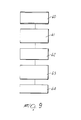
- the means 6A for simulating the average power overload comprise (see figure 9) a synchronization test circuit 60 which checks the synchronization of the device.
- the circuit 60 is connected to a unit 61 for managing the expected inhibition times, which calculates the expected inhibition times Tp, as clarified hereinafter.
- a stage 62 for checking the load disconnection conditions is connected, via the unit 61, to the management unit 60 and checks the conditions, as clarified hereinafter, under which the loads 2 can be disconnected from the power supply line 3; their possible reconnection is instead checked in a load- reconnection checking stage 63 which is arranged downstream of the stage 62.
- an interface 64 transmits the data generated by the stages and circuits 60, 61, 62 and 63 to the disconnection management unit 36 (figure 4), which performs the operations recommended by these data.
- the problem of managing the various users which form the total load is linked to a system of priorities: i.e., the more a load is indispensable during a certain period of the day, the higher is its priority. It is furthermore necessary to set an indispensable-power condition, i.e. the maximum power usable by the loads to which maximum priority is assigned.
- this maximum usable power is chosen equal to 60% of the maximum power, i.e. equal to the power value set in the supply contract.
- the maximum installable power by calculating all the loads it can be set equal to 200% of the power value contracted with the utility company.
- a priority level structure can be preset by selecting an absolute priority, in this case the structure comprising exclusively non-disconnectable, i.e. always-available, loads, an enhanced priority, a high priority, an average priority, and a low priority, i.e. a five-tier structure.
- an absolute priority in this case the structure comprising exclusively non-disconnectable, i.e. always-available, loads, an enhanced priority, a high priority, an average priority, and a low priority, i.e. a five-tier structure.
- this solution can vary, by providing a greater or smaller number of priority levels.
- At each priority level it is furthermore necessary to provide a maximum number of loads which can be managed, in order to avoid overloads.
- An alarm threshold S a for the disconnection of the loads set at the i-th level of priority, a load- reconnection threshold and a hysteresis inhibition time are assigned for each one of the above- mentioned priority levels.
- the overload condition for the disconnection of the loads of a generic level i is equal to:
- the inhibition time Tp is the assumed time period during which the loads of the i-th level of priority must remain disabled following the passing of the associated alarm threshold S a ,; until the average power drops below a reconnection threshold S r,i .
- This time period is a function of the average power P med , of the reconnection threshold Sr,, of the i-th level of priority, of the instantaneous power P ist and of a weighed power Pp eso associated with the i-th level, i.e.:
- the disconnection policy can follow the criterion of low-priority to high-priority, whereas the reconnection policy can follow the opposite direction.
- the broken line designated by the reference letter A represents the real consumption of a group of loads arranged on a power supply line without the device according to the invention
- the broken line designated by the reference letter B represents the real consumption of the same group of loads managed by means of the device according to the invention.
- line B never crosses the surcharge threshold, as instead occurs for line A.
- the present invention in addition to managing the loads according to the preceding description, emulates the operation of the magneto-thermal protection switch, in order to avoid the release of this switch on the watt-hour meter or rather on the meter of the utility company.
- Emulation is performed by selecting, by means of the keyboard 31 and the display 32, a model stored in the memory 33, which takes into account the current and temperature characteristics of various magneto-thermal protection switches, and a parameter, i.e. thermal sensitivity, which allows to delay or advance the response, i.e. the opening, of the switch.
- a model stored in the memory 33, which takes into account the current and temperature characteristics of various magneto-thermal protection switches, and a parameter, i.e. thermal sensitivity, which allows to delay or advance the response, i.e. the opening, of the switch.
- the emulation calculates the thermal state L i,t of the i-th priority level at the instant t according to the instantaneous current It at the instant t, to the regulation current I, for adjusting the magneto-thermal switch, to the characteristic parameters M and to the thermal sensitivity S of the selected thermal model, whereas the alarm threshold S t , i of the i-th priority level is calculated according to the thermal state Li,t and to the alarm threshold S a ,; of the i-th priority level, i.e.:
- the alarm state is verified if the condition Li,t > S a ,; occurs, and the i-th level is disabled, i.e. disconnected, for a period of not less than thirty seconds.
- the device according to the invention allows to optimize the behavior of the magneto-thermal switch by managing the instantaneous power-absorption peaks to limit interventions of the magneto-thermal switch caused by instantaneous overload.
- the device according to the invention optimizes the average power consumptions, distributing power demands in time, thus limiting the power engaged by the user.
- radio link to send connection and disconnection commands, it eliminates the need, well-known in currently marketed devices, to increase the number of wires in the local electric network to provide for a disconnection system.
- the materials employed, as well as the dimensions, may be any according to the requirements.
Applications Claiming Priority (2)
| Application Number | Priority Date | Filing Date | Title |
|---|---|---|---|
| ITMI922599 | 1992-11-12 | ||
| ITMI922599A IT1256105B (it) | 1992-11-12 | 1992-11-12 | Dispositivo di gestione e controllo di consumi particolarmente per impianti elettrici civili |
Publications (2)
| Publication Number | Publication Date |
|---|---|
| EP0597322A2 true EP0597322A2 (fr) | 1994-05-18 |
| EP0597322A3 EP0597322A3 (fr) | 1995-01-18 |
Family
ID=11364285
Family Applications (1)
| Application Number | Title | Priority Date | Filing Date |
|---|---|---|---|
| EP93117411A Withdrawn EP0597322A3 (fr) | 1992-11-12 | 1993-10-27 | Gestion de consommation et appareil de commande en particulier pour réseaux électriques civils. |
Country Status (2)
| Country | Link |
|---|---|
| EP (1) | EP0597322A3 (fr) |
| IT (1) | IT1256105B (fr) |
Cited By (10)
| Publication number | Priority date | Publication date | Assignee | Title |
|---|---|---|---|---|
| WO1995022190A1 (fr) * | 1994-02-15 | 1995-08-17 | Nazir Dosani | Procede et appareil de commande a distance d'une charge electrique |
| WO1995024759A1 (fr) * | 1994-03-11 | 1995-09-14 | Hyung Sik Park | Systeme de commutation |
| EP0688080A1 (fr) * | 1994-06-16 | 1995-12-20 | Schneider Electric Sa | Dispositif de gestion de puissance électrique d'une installation |
| AP456A (en) * | 1992-07-21 | 1996-02-01 | Csir | Load regulation system. |
| FR2790146A1 (fr) * | 1999-02-24 | 2000-08-25 | Sagem | Reseau de distribution d'energie a gestion dynamique de la charge et dispositif associe de controle de la consommation d'energie d'une installation |
| US7010363B2 (en) | 2003-06-13 | 2006-03-07 | Battelle Memorial Institute | Electrical appliance energy consumption control methods and electrical energy consumption systems |
| US7149605B2 (en) | 2003-06-13 | 2006-12-12 | Battelle Memorial Institute | Electrical power distribution control methods, electrical energy demand monitoring methods, and power management devices |
| EP1898292A1 (fr) | 2006-09-08 | 2008-03-12 | Eurosei S.r.l. | Procédé de gestion globale de la puissance électrique dans un réseau |
| US8183826B2 (en) | 2009-05-15 | 2012-05-22 | Battelle Memorial Institute | Battery charging control methods, electric vehicle charging methods, battery charging apparatuses and rechargeable battery systems |
| US9753440B2 (en) | 2010-04-06 | 2017-09-05 | Battelle Memorial Institute | Grid regulation services for energy storage devices based on grid frequency |
Citations (7)
| Publication number | Priority date | Publication date | Assignee | Title |
|---|---|---|---|---|
| EP0015666A1 (fr) * | 1979-02-21 | 1980-09-17 | South Eastern Electricity Board | Appareil pour commander la consommation d'énergie électrique |
| US4360881A (en) * | 1980-07-07 | 1982-11-23 | Martinson John R | Energy consumption control system and method |
| US4510398A (en) * | 1983-12-13 | 1985-04-09 | Honeywell Inc. | Add/shed load control according to multiple add/shed sequences |
| EP0250320A2 (fr) * | 1986-06-20 | 1987-12-23 | Manufacture D'appareillage Electrique De Cahors | Adaptateur de puissance pour installations électriques, notamment domestiques, à commande dite par courants porteurs |
| US4780910A (en) * | 1984-12-12 | 1988-10-25 | Scientific-Atlanta, Inc. | Display for a remote receiver in an electrical utility load management system |
| US4819180A (en) * | 1987-02-13 | 1989-04-04 | Dencor Energy Cost Controls, Inc. | Variable-limit demand controller for metering electrical energy |
| EP0372961A2 (fr) * | 1988-12-08 | 1990-06-13 | Honeywell Inc. | Commande de mise en ou hors service de charges avec méthode d'anticipation |
-
1992
- 1992-11-12 IT ITMI922599A patent/IT1256105B/it active IP Right Grant
-
1993
- 1993-10-27 EP EP93117411A patent/EP0597322A3/fr not_active Withdrawn
Patent Citations (7)
| Publication number | Priority date | Publication date | Assignee | Title |
|---|---|---|---|---|
| EP0015666A1 (fr) * | 1979-02-21 | 1980-09-17 | South Eastern Electricity Board | Appareil pour commander la consommation d'énergie électrique |
| US4360881A (en) * | 1980-07-07 | 1982-11-23 | Martinson John R | Energy consumption control system and method |
| US4510398A (en) * | 1983-12-13 | 1985-04-09 | Honeywell Inc. | Add/shed load control according to multiple add/shed sequences |
| US4780910A (en) * | 1984-12-12 | 1988-10-25 | Scientific-Atlanta, Inc. | Display for a remote receiver in an electrical utility load management system |
| EP0250320A2 (fr) * | 1986-06-20 | 1987-12-23 | Manufacture D'appareillage Electrique De Cahors | Adaptateur de puissance pour installations électriques, notamment domestiques, à commande dite par courants porteurs |
| US4819180A (en) * | 1987-02-13 | 1989-04-04 | Dencor Energy Cost Controls, Inc. | Variable-limit demand controller for metering electrical energy |
| EP0372961A2 (fr) * | 1988-12-08 | 1990-06-13 | Honeywell Inc. | Commande de mise en ou hors service de charges avec méthode d'anticipation |
Cited By (15)
| Publication number | Priority date | Publication date | Assignee | Title |
|---|---|---|---|---|
| AP456A (en) * | 1992-07-21 | 1996-02-01 | Csir | Load regulation system. |
| WO1995022190A1 (fr) * | 1994-02-15 | 1995-08-17 | Nazir Dosani | Procede et appareil de commande a distance d'une charge electrique |
| WO1995024759A1 (fr) * | 1994-03-11 | 1995-09-14 | Hyung Sik Park | Systeme de commutation |
| EP0688080A1 (fr) * | 1994-06-16 | 1995-12-20 | Schneider Electric Sa | Dispositif de gestion de puissance électrique d'une installation |
| FR2721449A1 (fr) * | 1994-06-16 | 1995-12-22 | Schneider Electric Sa | Dispositif de gestion de puissance électrique d'une installation. |
| FR2790146A1 (fr) * | 1999-02-24 | 2000-08-25 | Sagem | Reseau de distribution d'energie a gestion dynamique de la charge et dispositif associe de controle de la consommation d'energie d'une installation |
| US7010363B2 (en) | 2003-06-13 | 2006-03-07 | Battelle Memorial Institute | Electrical appliance energy consumption control methods and electrical energy consumption systems |
| US7149605B2 (en) | 2003-06-13 | 2006-12-12 | Battelle Memorial Institute | Electrical power distribution control methods, electrical energy demand monitoring methods, and power management devices |
| US7420293B2 (en) | 2003-06-13 | 2008-09-02 | Battelle Memorial Institute | Electrical appliance energy consumption control methods and electrical energy consumption systems |
| US8073573B2 (en) | 2003-06-13 | 2011-12-06 | Battelle Memorial Institute | Electrical power distribution control methods, electrical energy demand monitoring methods, and power management devices |
| EP1898292A1 (fr) | 2006-09-08 | 2008-03-12 | Eurosei S.r.l. | Procédé de gestion globale de la puissance électrique dans un réseau |
| EP1898292B1 (fr) * | 2006-09-08 | 2010-11-10 | Eurosei S.r.l. | Procédé de gestion globale de la puissance électrique dans un réseau |
| US8183826B2 (en) | 2009-05-15 | 2012-05-22 | Battelle Memorial Institute | Battery charging control methods, electric vehicle charging methods, battery charging apparatuses and rechargeable battery systems |
| US9753440B2 (en) | 2010-04-06 | 2017-09-05 | Battelle Memorial Institute | Grid regulation services for energy storage devices based on grid frequency |
| US10663932B2 (en) | 2010-04-06 | 2020-05-26 | Battelle Memorial Institute | Grid regulation services for energy storage devices based on grid frequency |
Also Published As
| Publication number | Publication date |
|---|---|
| ITMI922599A1 (it) | 1994-05-12 |
| EP0597322A3 (fr) | 1995-01-18 |
| IT1256105B (it) | 1995-11-28 |
| ITMI922599A0 (it) | 1992-11-12 |
Similar Documents
| Publication | Publication Date | Title |
|---|---|---|
| US5576700A (en) | Apparatus and method for controlling an electrical load and monitoring control operations and the electrical load | |
| US5513061A (en) | Apparatus and method for distributing electrical power | |
| CN101194217B (zh) | 使用固态功率控制器的配电系统 | |
| US4349879A (en) | Apparatus for controlling electrical power consumption | |
| JP4920890B2 (ja) | 電気回路ブレーカ | |
| EP0044181B1 (fr) | Système d'alimentation en puissance électrique à courant alternatif et procédés et appareil de commande de la charge de celui-ci | |
| US6985784B2 (en) | Configuring a centrally controlled circuit breaker protection system | |
| US5581132A (en) | Peak demand limiter and sequencer | |
| US4390876A (en) | Electric utility demand limiting device and method | |
| EP1005133B1 (fr) | Système de distribution d'énergie avec disjoncteurs réarmables à distance par des signaux transmis par les lignes de distribution | |
| US7058482B2 (en) | Data sample and transmission modules for power distribution systems | |
| US7356385B2 (en) | End-user electrical load controller | |
| EP0597322A2 (fr) | Gestion de consommation et appareil de commande en particulier pour réseaux électriques civils | |
| AU2361199A (en) | Dual microprocessor electronic trip unit for a circuit interrupter | |
| AU2006306688A1 (en) | Fault protection system and method for an electrical power distribution system | |
| ES2121560A1 (es) | Avisador programable de consumo electrico. | |
| NZ280922A (en) | Overcurrent protection switch interfaced to remote station and local portable unit | |
| US5272585A (en) | System to prevent electrical shorts by a microprocessor breaker box | |
| JPH0993784A (ja) | 節電及び過負荷回避装置とそれを用いた節電及び過負荷回避方法 | |
| CA2662230A1 (fr) | Methode de reglage d'une fonction de declenchement de fuite a la terre et une unite de declenchement ayant une fonction de declenchement definie pour une protection contre les fuites a la terre | |
| US5390066A (en) | Protection device for electrical appliances, machines and installations | |
| KR20000006898A (ko) | 전력부하 제어기능을 갖는 전자식전력량계 | |
| JP2004153963A (ja) | デマンドコントロール受配電設備 | |
| JPH09200963A (ja) | 負荷選択遮断装置 | |
| EP1448997A2 (fr) | Unite de commande de consommation d'energie |
Legal Events
| Date | Code | Title | Description |
|---|---|---|---|
| PUAI | Public reference made under article 153(3) epc to a published international application that has entered the european phase |
Free format text: ORIGINAL CODE: 0009012 |
|
| AK | Designated contracting states |
Kind code of ref document: A2 Designated state(s): CH DE FR GB IT LI |
|
| PUAL | Search report despatched |
Free format text: ORIGINAL CODE: 0009013 |
|
| AK | Designated contracting states |
Kind code of ref document: A3 Designated state(s): CH DE FR GB IT LI |
|
| 17P | Request for examination filed |
Effective date: 19950408 |
|
| 17Q | First examination report despatched |
Effective date: 19951212 |
|
| GRAG | Despatch of communication of intention to grant |
Free format text: ORIGINAL CODE: EPIDOS AGRA |
|
| GRAG | Despatch of communication of intention to grant |
Free format text: ORIGINAL CODE: EPIDOS AGRA |
|
| GRAH | Despatch of communication of intention to grant a patent |
Free format text: ORIGINAL CODE: EPIDOS IGRA |
|
| STAA | Information on the status of an ep patent application or granted ep patent |
Free format text: STATUS: THE APPLICATION HAS BEEN WITHDRAWN |
|
| 18W | Application withdrawn |
Withdrawal date: 19971110 |