EP0596390A1 - Die plate for the production of carton box blanks - Google Patents
Die plate for the production of carton box blanks Download PDFInfo
- Publication number
- EP0596390A1 EP0596390A1 EP93117339A EP93117339A EP0596390A1 EP 0596390 A1 EP0596390 A1 EP 0596390A1 EP 93117339 A EP93117339 A EP 93117339A EP 93117339 A EP93117339 A EP 93117339A EP 0596390 A1 EP0596390 A1 EP 0596390A1
- Authority
- EP
- European Patent Office
- Prior art keywords
- die
- layer
- carrier film
- plate
- die sheet
- Prior art date
- Legal status (The legal status is an assumption and is not a legal conclusion. Google has not performed a legal analysis and makes no representation as to the accuracy of the status listed.)
- Granted
Links
Images
Classifications
-
- B—PERFORMING OPERATIONS; TRANSPORTING
- B26—HAND CUTTING TOOLS; CUTTING; SEVERING
- B26F—PERFORATING; PUNCHING; CUTTING-OUT; STAMPING-OUT; SEVERING BY MEANS OTHER THAN CUTTING
- B26F1/00—Perforating; Punching; Cutting-out; Stamping-out; Apparatus therefor
- B26F1/38—Cutting-out; Stamping-out
- B26F1/44—Cutters therefor; Dies therefor
-
- B—PERFORMING OPERATIONS; TRANSPORTING
- B26—HAND CUTTING TOOLS; CUTTING; SEVERING
- B26F—PERFORATING; PUNCHING; CUTTING-OUT; STAMPING-OUT; SEVERING BY MEANS OTHER THAN CUTTING
- B26F1/00—Perforating; Punching; Cutting-out; Stamping-out; Apparatus therefor
- B26F1/38—Cutting-out; Stamping-out
- B26F1/40—Cutting-out; Stamping-out using a press, e.g. of the ram type
-
- B—PERFORMING OPERATIONS; TRANSPORTING
- B26—HAND CUTTING TOOLS; CUTTING; SEVERING
- B26F—PERFORATING; PUNCHING; CUTTING-OUT; STAMPING-OUT; SEVERING BY MEANS OTHER THAN CUTTING
- B26F1/00—Perforating; Punching; Cutting-out; Stamping-out; Apparatus therefor
- B26F1/38—Cutting-out; Stamping-out
- B26F1/44—Cutters therefor; Dies therefor
- B26F2001/4445—Matrices, female dies, creasing tools
-
- B—PERFORMING OPERATIONS; TRANSPORTING
- B31—MAKING ARTICLES OF PAPER, CARDBOARD OR MATERIAL WORKED IN A MANNER ANALOGOUS TO PAPER; WORKING PAPER, CARDBOARD OR MATERIAL WORKED IN A MANNER ANALOGOUS TO PAPER
- B31B—MAKING CONTAINERS OF PAPER, CARDBOARD OR MATERIAL WORKED IN A MANNER ANALOGOUS TO PAPER
- B31B50/00—Making rigid or semi-rigid containers, e.g. boxes or cartons
- B31B50/25—Surface scoring
- B31B50/252—Surface scoring using presses or dies
Definitions
- the invention relates to a die sheet for a punching tool for producing cardboard blanks, which can be glued to an essentially rigid tool plate and has a layer facing the male part of the punching tool.
- a punching tool for folding boxes for embossing the folding lines and for punching out box blanks is known.
- the matrix and male are produced by a relatively complex phototechnical process, in which a plate coated with a light-sensitive layer is exposed with the interposition of an embossing line or groove line film and the exposed areas of the plates are then washed out. Elevations from remaining residues of the light-sensitive layer are then arranged on the metal plate in accordance with the male or female profile.
- die sheets for punching tools for producing cardboard blanks which consist of a phenolic hard paper board with fabric inserts. These matrix sheets are glued to the tool plate using a pressure sensitive adhesive. Depending on the size and shape of the punching tool, the die sheet is provided with a counter contour corresponding to the male part by milling tools. In particular, grooved grooves are milled into the die sheet, on which the folding grooves are produced during the production of the cardboard blanks.
- the processing accuracy and material thickness of the matrix sheets depend on the quality of the cardboard to be processed. In the area of the creasing grooves, the sheet material is milled down to a remaining thickness of approx. 0.1 mm. The remaining material at the bottom of the groove essentially consists of the lowest fabric insert. It is not possible to reuse the die sheet applied with the pressure sensitive adhesive, since this will inevitably break when removed from the tool plate. Therefore, the template sheets have to be prepared for each changing order, which leads to increased costs and time.
- the die sheet is designed as a composite plate, in which the layer facing the die is applied to a flexible carrier film releasably attachable to the tool plate, the bottom of the groove being formed by the carrier film from the die sheet, while the lateral groove edges are formed by the layer applied thereon.
- a flexible carrier film By using a flexible carrier film, movable hinges are formed, after the milling of the creasing grooves, distributed over the entire matrix sheet, which gives the entire matrix sheet a very flexible structure.
- This flexible structure makes it possible to remove the die sheet from the tool plate after the completion of an order for the production of a cardboard blank without the layer, which has been milled down into individual parts, being broken. Furthermore, punching tools and the associated die sheet can now be stored together and retrieved as quickly as possible, whereby a new die sheet is not necessary. This saves enormous costs and processing times.
- a die roller is known from EP-A-0312422, in which metal plates which are elastically deformable in segments and with elevations by means of magnetic force are arranged on the outer circumference.
- this is not a composite plate, the layer facing the male part of which is applied to a flexible carrier film which can be releasably attached to the tool plate.
- the carrier film is made of polyester. These foils are particularly inexpensive and accordingly well suited for the application.
- the layer is preferably produced from phenolic hard paper boards which have proven particularly useful for use in corresponding punching machines for producing cardboard blanks.
- Phenol hard paper sheets with fabric inserts are preferably used.
- the carrier film and / or the tool plate can be releasably connected by an adhesive layer that is self-adhesive on both sides.
- This connection method is particularly simple and inexpensive for the intended application.
- the flexible carrier film 1 consists of a carrier film 1 and a layer 2, preferably made of phenol hard paper with a fabric insert.
- the flexible carrier film 1 and the layer 2 are preferably connected to one another by an adhesive layer applied to the carrier film on one side.
- the flexible carrier film 1 is preferably made of polyester.
- the composite plate 3 thus formed is used as a die sheet for a punching tool for producing cardboard blanks. Such a tool is usually a band steel cutting tool, the surface contour of which is occupied by stamping dies and knives. As can be seen in FIGS. 2 and 3, matching counter contours must now be worked out from the composite plate 3 in accordance with the embossing dies or strips and the knives in order to produce a die from the die sheet.
- grooves 4 are milled out of the top of the composite plate 3 in accordance with the impression of the punching tool. These creasing grooves 4 have a depth that extends to the surface of the carrier film 1. While the base of the creasing grooves 4 is formed by the carrier film 1, the side walls are formed by the layer 2 applied thereon. At the points where the knives are later to cut the cardboard sheet to be processed, layer 2 is completely removed.
- the creasing grooves 4, on the other hand, are mainly used to produce folding creases in cooperation with the male dies.
- the die sheet is glued to a tool plate 5 by a self-adhesive layer on both sides.
- the adhesive layer can be located on the back of the carrier film 1 or on the surface of the tool plate.
- the adhesive layer used has the property that the die sheet can be easily detached from the tool plate.
- the carrier film 1 has a hinge effect at the bottom of the creasing grooves 4, which leads to the fact that the entire matrix sheet has a relatively great flexibility.
- the deformation when the matrix sheet is released does not therefore have to be absorbed by the relatively brittle layer 2, but takes place entirely via the carrier film 1.
- a breakage of the layer 2 of hard phenolic paper, as is known from the prior art, is therefore made in the matrix sheet according to the invention the composite panel 3 does not take place.
Landscapes
- Life Sciences & Earth Sciences (AREA)
- Forests & Forestry (AREA)
- Engineering & Computer Science (AREA)
- Mechanical Engineering (AREA)
- Making Paper Articles (AREA)
- Perforating, Stamping-Out Or Severing By Means Other Than Cutting (AREA)
Abstract
Description
Die Efindung bezieht sich auf einen Matrizenbogen für ein Stanzwerkzeug zum Herstellen von Kartonagenzuschnitten, der auf eine im wesentlichen biegesteife Werkzeugplatte aufklebbar ist und eine der Patrize des Stanzwerkzeuges zugewandte Schicht aufweist.The invention relates to a die sheet for a punching tool for producing cardboard blanks, which can be glued to an essentially rigid tool plate and has a layer facing the male part of the punching tool.
Aus der DE-A-2546082 ist ein Stanzwerkzeug für Faltschachteln zum Prägen der Faltlinien und zum Ausstanzen von Schachtelzuschnitten bekannt. Die Matrize und Patrize werden durch ein relativ aufwendiges phototechnisches Verfahren hergestellt, bei dem eine mit einer lichtempfindlichen Schicht beschichtete Platte unter Zwischenschaltung eines Prägelinien- beziehungsweise Nutlinienfilms belichtet und die belichteten Stellen der Platten sodann ausgewaschen werden. Auf der Metallplatte sind dann entsprechend des Patrizen- beziehungsweise Matrizenprofils Erhebungen aus verbleibenden Resten der lichtempfindlichen Schicht angeordnet.From DE-A-2546082 a punching tool for folding boxes for embossing the folding lines and for punching out box blanks is known. The matrix and male are produced by a relatively complex phototechnical process, in which a plate coated with a light-sensitive layer is exposed with the interposition of an embossing line or groove line film and the exposed areas of the plates are then washed out. Elevations from remaining residues of the light-sensitive layer are then arranged on the metal plate in accordance with the male or female profile.
Aus dem Stand der Technik sind weiterhin Matrizenbogen für Stanzwerkzeuge zum Herstellen von Kartonagenzuschnitten bekannt, die aus einer Phenol-Hartpapiertafel mit Gewebeeinlagen bestehen. Diese Matrizenbogen werden mittels eines Haftklebers auf die Werkzeugplatte geklebt. Entsprechend der Größe und Form des Stanzwerkzeugs wird der Matrizenbogen durch Fräswerkzeuge mit einer der Patrize entsprechende Gegenkontur versehen. Insbesondere werden Rillnuten in den Matrizenbogen eingefräst, an denen bei der Herstellung der Kartonagenzuschnitte die Faltrillen erzeugt werden. Die Bearbeitungsgenauigkeit und Materialstärke der Matrizenbogen richtet sich hierbei nach der zu verarbeitenden Kartonqualität. Im Bereich der Rillnuten wird das Tafelmaterial bis auf eine verbleibende Restdicke von ca. 0,1 mm abgefräst. Das verbleibende Restmaterial am Nutgrund besteht im wesentlichen aus der untersten Gewebeeinlage. Ein Wiederverwenden des mit dem Haftkleber aufgebrachten Matrizenbogens ist nicht möglich, da dieser beim Abziehen von der Werkzeugplatte zwangsläufig zerbricht. Deshalb müssen für jeden wechselnden Auftrag die Matrizenbogen neu angefertigt werden, was zu einem erhöhten Kosten- und Zeitaufwand führt.Also known from the prior art are die sheets for punching tools for producing cardboard blanks, which consist of a phenolic hard paper board with fabric inserts. These matrix sheets are glued to the tool plate using a pressure sensitive adhesive. Depending on the size and shape of the punching tool, the die sheet is provided with a counter contour corresponding to the male part by milling tools. In particular, grooved grooves are milled into the die sheet, on which the folding grooves are produced during the production of the cardboard blanks. The processing accuracy and material thickness of the matrix sheets depend on the quality of the cardboard to be processed. In the area of the creasing grooves, the sheet material is milled down to a remaining thickness of approx. 0.1 mm. The remaining material at the bottom of the groove essentially consists of the lowest fabric insert. It is not possible to reuse the die sheet applied with the pressure sensitive adhesive, since this will inevitably break when removed from the tool plate. Therefore, the template sheets have to be prepared for each changing order, which leads to increased costs and time.
Es ist daher die Aufgabe der vorliegenden Erfindung, einen Matrizenbogen zur Verfügung zu stellen, der wiederholt eingesetzt werden kann.It is therefore the object of the present invention to provide a matrix sheet which can be used repeatedly.
Diese Aufgabe wird erfindungsgemäß dadurch gelöst, daß der Matrizenbogen als Verbundplatte ausgebildet ist, bei der die der Matrize zugewandte Schicht auf einer flexiblen auf die Werkzeugplatte lösbar aufklebbaren Trägerfolie aufgebracht ist, wobei der Nutgrund der aus dem Matrizenbogen herausfräsbaren durch die Trägerfolie gebildet ist, während die seitlichen Nutränder durch die darauf aufgebrachte Schicht gebildet sind. Durch das Verwenden einer flexiblen Trägerfolie werden nach dem Einfräsen der Rillnuten über den gesamten Matrizenbogen verteilt bewegliche Scharniere gebildet, durch die der gesamte Matrizenbogen eine sehr flexible Struktur erhält. Diese flexible Struktur ermöglicht es, den Matrizenbogen nach der Beendigung eines Auftrages zur Herstellung eines Kartonagenzuschnitts wieder von der Werkzeugplatte zu entfernen, ohne daß die in lauter Einzelteile zerfräste Schicht brechen würde. Weiterhin können nun Stanzwerkzeuge und dazugehörige Matrizenbogen zusammen auf Lager gelegt und schnellstmöglich wieder abgerufen werden, wobei eine Neuerstellung eines Matrizenbogens nicht notwendig ist. Hierdurch werden enorme Kosten und Bearbeitungszeiten eingespart.This object is achieved in that the die sheet is designed as a composite plate, in which the layer facing the die is applied to a flexible carrier film releasably attachable to the tool plate, the bottom of the groove being formed by the carrier film from the die sheet, while the lateral groove edges are formed by the layer applied thereon. By using a flexible carrier film, movable hinges are formed, after the milling of the creasing grooves, distributed over the entire matrix sheet, which gives the entire matrix sheet a very flexible structure. This flexible structure makes it possible to remove the die sheet from the tool plate after the completion of an order for the production of a cardboard blank without the layer, which has been milled down into individual parts, being broken. Furthermore, punching tools and the associated die sheet can now be stored together and retrieved as quickly as possible, whereby a new die sheet is not necessary. This saves enormous costs and processing times.
Zwar ist aus der EP-A-0312422 eine Matrizenwalze bekannt, bei der segmentweise elastisch verformbare Metallplatten mit Erhöhungen mittels Magnetkraft am Außenumfang angeordnet sind. Jedoch handelt es sich hier nicht um eine Verbundplatte, deren der Patrize zugewandte Schicht auf einer flexiblen auf die Werkzeugplatte lösbar aufklebbaren Trägerfolie aufgebracht ist.A die roller is known from EP-A-0312422, in which metal plates which are elastically deformable in segments and with elevations by means of magnetic force are arranged on the outer circumference. However, this is not a composite plate, the layer facing the male part of which is applied to a flexible carrier film which can be releasably attached to the tool plate.
Weiterhin ist im Stand der Technik nicht bekannt, Rillnuten aus aus einem Matrizenbogen mit einer Trägerfolie als Nutgrund herauszufräsen, wobei die Trägerfolie lösbar aufklebbar auf die Werkzeugplatte ist.Furthermore, it is not known in the prior art to mill creases out of a die sheet with a carrier film as the groove base, the carrier film being releasably stuck onto the tool plate.
Von Vorteil ist es, wenn die Trägerfolie aus Polyester hergestellt ist. Diese Folien sind besonders preiswert und entsprechend für den Einsatzfall gut geeignet.It is advantageous if the carrier film is made of polyester. These foils are particularly inexpensive and accordingly well suited for the application.
Vorzugsweise wird die Schicht aus Phenol- Hartpapiertafeln hergestellt, welche sich für den Einsatz in entsprechenden Stanzmaschinen zur Herstellung von Kartonagenzuschnitten besonders bewährt haben.The layer is preferably produced from phenolic hard paper boards which have proven particularly useful for use in corresponding punching machines for producing cardboard blanks.
Bevorzugt werden hierbei Phenol-Hartpapiertafeln mit Gewebeeinlagen verwendet.Phenol hard paper sheets with fabric inserts are preferably used.
In einer bevorzugten Ausführungsform sind die Trägerfolie und/oder die Werkzeugplatte durch eine beidseitig selbstklebende Klebschicht lösbar verbindbar. Diese Verbindungsmethode ist für den vorgesehenen Einsatzfall besonders einfach und preisgünstig.In a preferred embodiment, the carrier film and / or the tool plate can be releasably connected by an adhesive layer that is self-adhesive on both sides. This connection method is particularly simple and inexpensive for the intended application.
Vorteilhafterweise wird die Trägerfolie einseitig mit einer Klebeschicht versehen, auf der die Schicht aufgebracht ist. Im folgenden wird die Erfindung anhand eines Ausführungsbeispieles des erfindungsgemäßen Matrizenbogens näher erläutert. Es zeigen:
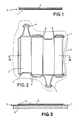
- Fig. 1 einen Querschnitt eines erfindungsgemäßen Matrizenbogens,
- Fig. 2 einen vergrößerten Ausschnitt des bearbeiteten und auf einer Werkzeugplatte aufgebrachten Matrizenbogens in einer Draufsicht, und
- Fig. 3 den Auschnitt des bearbeiteten Matrizenbogens aus Fig. 2 in einer Schnittdarstellung entlang der Linie I-I.
- 1 shows a cross section of a die sheet according to the invention,
- Fig. 2 is an enlarged section of the machined and applied to a tool plate die sheet in a plan view, and
- 3 shows the section of the machined die sheet from FIG. 2 in a sectional view along the line II.
Der Matrizenbogen gemäß Fig. 1 besteht aus einer Trägerfolie 1 und einer bevorzugt aus Phenol-Hartpapier mit Gewebeeinlage bestehenden Schicht 2. Die flexible Trägerfolie 1 und die Schicht 2 sind bevorzugt durch eine einseitig auf die Trägerfolie aufgebrachte Klebeschicht miteinander verbunden. Die flexible Trägerfolie 1 besteht bevorzugt aus Polyester. Die so gebildete Verbundplatte 3 wird als Matrizenbogen für ein Stanzwerkzeug zum Herstellen von Kartonagenzuschnitten verwendet. Bei einem solchen Werkzeug handelt es sich meistens um ein Bandstahlschnitt-Werkzeug, dessen Oberflächenkontur von Prägestempeln und Messern besetzt ist. Wie in den Fig. 2 und 3 zu sehen ist, müssen nun entsprechend den Prägestempeln bzw. -leisten und den Messern, um aus dem Matrizenbogen eine Matrize herzustellen, dazu passende Gegenkonturen aus der Verbundplatte 3 herausgearbeitet werden. Hierzu werden entsprechend dem Abdruck des Stanzwerkzeugs Rillnuten 4 aus der Oberseite der Verbundplatte 3 herausgefräst. Diese Rillnuten 4 weisen eine Tiefe auf, die sich bis zur Oberfläche der Trägerfolie 1 erstreckt. Während der Grund der Rillnuten 4 durch die Trägerfolie 1 gebildet wird, werden die Seitenwände durch die darauf aufgebrachte Schicht 2 gebildet. An den Stellen, wo später die Messer den zu bearbeitenden Kartonagenbogen durchtrennen sollen, wird die Schicht 2 gänzlich abgetragen. Die Rillnuten 4 hingegen dienen hauptsächlich zur Erzeugung von Faltrillen in Zusammenarbeit mit den Prägestempeln der Patrize.1 consists of a carrier film 1 and a
Während des Einsatzes in einer Stanzmaschine ist der Matrizenbogen auf einer Werkzeugplatte 5 durch eine beidseitig selbstklebende Klebeschicht aufgeklebt. Die Klebeschicht kann sich auf der Rückseite der Trägerfolie 1 oder auf der Oberfläche der Werkzeugplatte befinden. Die verwendete Klebeschicht hat die Eigenschaft, daß sich der Matrizenbogen von der Werkzeugplatte wieder leicht lösen läßt. Bei diesem Loslösevorgang weist die Trägerfolie 1 am Grund der Rillnuten 4 eine Scharnierwirkung auf, die dazu führt, daß der gesamte Matrizenbogen eine relativ große Flexibilität erlangt. Die Verformung beim Loslösen des Matrizenbogens muß daher nicht von der relativ spröden Schicht 2 aufgefangen werden, sondern erfolgt gänzlich über die Trägerfolie 1. Ein Zerbrechen der Schicht 2 aus Phenol-Hartpapier, wie aus dem Stand der Technik bekannt, wird daher beim erfindungsgemäßen Matrizenbogen aus der Verbundplatte 3 nicht erfolgen.During use in a punching machine, the die sheet is glued to a
Durch die so gewonnene Wiederverwendbarkeit der Matrizenbogen, die zusammen mit den entsprechenden Stanzwerkzeugen auf Lager gelegt werden können, wird eine große Kosten- und Zeitreduzierung bewirkt. Bei wechselnden Aufträgen müssen nunmehr nicht jeweils neue Matrizenbogen angefertigt werden, da diese für einen wiederkehrenden Auftrag bereits fertiggestellt im Lager vorhanden sind.The reusability of the die sheets, which can be stored together with the corresponding punching tools, results in a great reduction in costs and time. In the case of changing orders, it is no longer necessary to produce new matrix sheets, since these are already available in the warehouse for a recurring order.
Claims (7)
Applications Claiming Priority (3)
| Application Number | Priority Date | Filing Date | Title |
|---|---|---|---|
| DE9214654U | 1992-10-28 | ||
| DE9214654U DE9214654U1 (en) | 1992-10-28 | 1992-10-28 | Die sheet for a punching tool for making cardboard blanks |
| US08/237,112 US5517880A (en) | 1992-10-28 | 1994-05-03 | Bottom die for a stamping tool for producing cardboard blanks |
Publications (2)
| Publication Number | Publication Date |
|---|---|
| EP0596390A1 true EP0596390A1 (en) | 1994-05-11 |
| EP0596390B1 EP0596390B1 (en) | 1997-01-22 |
Family
ID=25960079
Family Applications (1)
| Application Number | Title | Priority Date | Filing Date |
|---|---|---|---|
| EP93117339A Expired - Lifetime EP0596390B1 (en) | 1992-10-28 | 1993-10-26 | Die plate for the production of carton box blanks |
Country Status (3)
| Country | Link |
|---|---|
| US (1) | US5517880A (en) |
| EP (1) | EP0596390B1 (en) |
| DE (1) | DE9214654U1 (en) |
Cited By (3)
| Publication number | Priority date | Publication date | Assignee | Title |
|---|---|---|---|---|
| WO2002038367A1 (en) * | 2000-11-10 | 2002-05-16 | Man Roland Druckmaschinen Ag | Punching device |
| BE1019058A3 (en) * | 2009-12-03 | 2012-02-07 | Rillivo Bvba Bv Met Beperkte Aansprakelijkheid | STANDING PLATE OR CUTTING PLATE. |
| DE102014003294A1 (en) * | 2014-03-07 | 2015-09-10 | Masterwork Machinery Co., Ltd. | Stripping tool for a punching machine |
Families Citing this family (3)
| Publication number | Priority date | Publication date | Assignee | Title |
|---|---|---|---|---|
| GB9601827D0 (en) * | 1996-01-30 | 1996-04-03 | Trimplex Ltd | Creasing machine |
| US20080105396A1 (en) * | 2006-11-02 | 2008-05-08 | Sonoco Development, Inc. | Rotary Die Board |
| EP2036659B1 (en) * | 2007-09-12 | 2010-12-01 | Foppa Fustelle S.r.l. | Process for manufacturing a counter-die for blanking cardboard |
Citations (5)
| Publication number | Priority date | Publication date | Assignee | Title |
|---|---|---|---|---|
| DE2445652A1 (en) * | 1973-10-10 | 1975-04-17 | Centenary Central | METHOD OF MANUFACTURING STAMPING TOOLS |
| DE2546082A1 (en) * | 1975-10-15 | 1977-04-21 | Stanztechnik Gmbh Roeder & Spe | Cutting tool for making cardboard box blanks - uses multi stage photographic reproduction techniques for forming matrix for punch |
| DE2831619A1 (en) * | 1978-07-19 | 1980-02-21 | Marbach Gmbh | PUNCHING AND SCRAPING TOOL |
| EP0312422A1 (en) * | 1987-10-12 | 1989-04-19 | Jean-Jacques Buland | Rotary cutting device |
| FR2639000A1 (en) * | 1988-11-15 | 1990-05-18 | Roy Christian | Device for assembling cutting-out tool elements for materials in sheet form |
Family Cites Families (2)
| Publication number | Priority date | Publication date | Assignee | Title |
|---|---|---|---|---|
| US3884132A (en) * | 1974-01-11 | 1975-05-20 | Channel Creasing Matrix Inc | Magnetically located scoring die matrix |
| US5143768A (en) * | 1991-08-30 | 1992-09-01 | Weyerhaeuser Company | Laminated dieboard structure |
-
1992
- 1992-10-28 DE DE9214654U patent/DE9214654U1/en not_active Expired - Lifetime
-
1993
- 1993-10-26 EP EP93117339A patent/EP0596390B1/en not_active Expired - Lifetime
-
1994
- 1994-05-03 US US08/237,112 patent/US5517880A/en not_active Expired - Lifetime
Patent Citations (5)
| Publication number | Priority date | Publication date | Assignee | Title |
|---|---|---|---|---|
| DE2445652A1 (en) * | 1973-10-10 | 1975-04-17 | Centenary Central | METHOD OF MANUFACTURING STAMPING TOOLS |
| DE2546082A1 (en) * | 1975-10-15 | 1977-04-21 | Stanztechnik Gmbh Roeder & Spe | Cutting tool for making cardboard box blanks - uses multi stage photographic reproduction techniques for forming matrix for punch |
| DE2831619A1 (en) * | 1978-07-19 | 1980-02-21 | Marbach Gmbh | PUNCHING AND SCRAPING TOOL |
| EP0312422A1 (en) * | 1987-10-12 | 1989-04-19 | Jean-Jacques Buland | Rotary cutting device |
| FR2639000A1 (en) * | 1988-11-15 | 1990-05-18 | Roy Christian | Device for assembling cutting-out tool elements for materials in sheet form |
Cited By (4)
| Publication number | Priority date | Publication date | Assignee | Title |
|---|---|---|---|---|
| WO2002038367A1 (en) * | 2000-11-10 | 2002-05-16 | Man Roland Druckmaschinen Ag | Punching device |
| CZ299949B6 (en) * | 2000-11-10 | 2009-01-07 | Manroland Ag | Device for punching, grooving, perforating or embossing |
| BE1019058A3 (en) * | 2009-12-03 | 2012-02-07 | Rillivo Bvba Bv Met Beperkte Aansprakelijkheid | STANDING PLATE OR CUTTING PLATE. |
| DE102014003294A1 (en) * | 2014-03-07 | 2015-09-10 | Masterwork Machinery Co., Ltd. | Stripping tool for a punching machine |
Also Published As
| Publication number | Publication date |
|---|---|
| EP0596390B1 (en) | 1997-01-22 |
| DE9214654U1 (en) | 1994-03-03 |
| US5517880A (en) | 1996-05-21 |
Similar Documents
| Publication | Publication Date | Title |
|---|---|---|
| DE102009056169A1 (en) | Method of trimming tools | |
| EP0108761B1 (en) | Method and device for perforating, punching or grooving paper and cardboard in a rotary press | |
| DE102012017636A1 (en) | Method for determining the need for dressing and method for creating a finishing bow | |
| DE2756691C3 (en) | Multi-layer edge-welded recording medium | |
| WO2006077134A1 (en) | Stamping tool in a printing mechanism with a matrix and punch | |
| DE10110563A1 (en) | Process for the production of hollow embossed packaging and other objects from sheet materials, raw sheets produced therefrom and sheet materials which are used in this process | |
| DE102006003037A1 (en) | Embossment producing method for use by sheet-fed offset printing machine, involves mounting embossing die as part of multipart impression mold on cylinder, where mold is combined with another impression mold forming counter tool | |
| EP0596390B1 (en) | Die plate for the production of carton box blanks | |
| DE102009034437A1 (en) | Contour formation device i.e. individual card punching machine, for formation of contour in body of chip card, has sheet metals and magnet bed that are pressed against each other, where body is grooved between metals and magnet bed | |
| DE60207385T2 (en) | METHOD FOR PRODUCING A NOTEPAD | |
| DE2831619A1 (en) | PUNCHING AND SCRAPING TOOL | |
| DE3718452C2 (en) | ||
| EP1640938B1 (en) | Method and system for cutting and embossing of folded box blanks | |
| EP0790110B1 (en) | Cutting and creasing die for the production of creased and cut shapes | |
| DE202004001738U1 (en) | Device for punching packaging elements or the like. | |
| DE2265153B2 (en) | Tool for punching machines | |
| DE19617688A1 (en) | Method and stripping tool for stripping punch waste in the production of blanks from a sheet | |
| DE3630412C2 (en) | ||
| DE102019104380A1 (en) | Method for producing a value or security document and security document with a security hologram | |
| DE60204002T2 (en) | EXTRACTION TOOL OF PLASTIC FOAM | |
| DE102016206668A1 (en) | Method for setting up a processing station of a printing machine | |
| DE102022116427A1 (en) | Method for processing a surface of a pressing tool | |
| DE102022116424A1 (en) | Pressing tool for pressing material panels in heating presses | |
| DE102022116423A1 (en) | Pressing tool and method for producing a pressing tool | |
| DE3306435C1 (en) | Method of producing a multicolour plate proof for floor design proofs, decorative prints and the like |
Legal Events
| Date | Code | Title | Description |
|---|---|---|---|
| PUAI | Public reference made under article 153(3) epc to a published international application that has entered the european phase |
Free format text: ORIGINAL CODE: 0009012 |
|
| 17P | Request for examination filed |
Effective date: 19931026 |
|
| AK | Designated contracting states |
Kind code of ref document: A1 Designated state(s): AT BE CH DE FR GB IT LI NL |
|
| 17Q | First examination report despatched |
Effective date: 19950201 |
|
| GRAG | Despatch of communication of intention to grant |
Free format text: ORIGINAL CODE: EPIDOS AGRA |
|
| GRAH | Despatch of communication of intention to grant a patent |
Free format text: ORIGINAL CODE: EPIDOS IGRA |
|
| GRAH | Despatch of communication of intention to grant a patent |
Free format text: ORIGINAL CODE: EPIDOS IGRA |
|
| GRAA | (expected) grant |
Free format text: ORIGINAL CODE: 0009210 |
|
| AK | Designated contracting states |
Kind code of ref document: B1 Designated state(s): AT BE CH DE FR GB IT LI NL |
|
| REF | Corresponds to: |
Ref document number: 148029 Country of ref document: AT Date of ref document: 19970215 Kind code of ref document: T |
|
| REG | Reference to a national code |
Ref country code: CH Ref legal event code: NV Representative=s name: PATENTANWALTSBUERO JEAN HUNZIKER Ref country code: CH Ref legal event code: EP |
|
| GBT | Gb: translation of ep patent filed (gb section 77(6)(a)/1977) |
Effective date: 19970122 |
|
| REF | Corresponds to: |
Ref document number: 59305237 Country of ref document: DE Date of ref document: 19970306 |
|
| ITF | It: translation for a ep patent filed |
Owner name: 0508;05TOFJACOBACCI & PERANI S.P.A. |
|
| ET | Fr: translation filed | ||
| REG | Reference to a national code |
Ref country code: CH Ref legal event code: PFA Free format text: PCE PAPER CONVERTING EQUIPMENT GMBH,GAERTNERPLATZ 16,D-93073 NEUTRAUBLING (DE) TRANSFER- PCE PAPER CONVERTING EQUIPMENT GMBH,ORCHIDEENSTRASSE 30,D-90542 ECKENTAL/BRAND (DE) |
|
| RAP2 | Party data changed (patent owner data changed or rights of a patent transferred) |
Owner name: PCE PAPER CONVERTING EQUIPMENT GMBH |
|
| NLT2 | Nl: modifications (of names), taken from the european patent patent bulletin |
Owner name: PCE PAPER CONVERTING EQUIPMENT GMBH |
|
| REG | Reference to a national code |
Ref country code: FR Ref legal event code: CA |
|
| PLBE | No opposition filed within time limit |
Free format text: ORIGINAL CODE: 0009261 |
|
| STAA | Information on the status of an ep patent application or granted ep patent |
Free format text: STATUS: NO OPPOSITION FILED WITHIN TIME LIMIT |
|
| 26N | No opposition filed | ||
| PGFP | Annual fee paid to national office [announced via postgrant information from national office to epo] |
Ref country code: GB Payment date: 20010119 Year of fee payment: 8 Ref country code: CH Payment date: 20010119 Year of fee payment: 8 Ref country code: AT Payment date: 20010119 Year of fee payment: 8 |
|
| PGFP | Annual fee paid to national office [announced via postgrant information from national office to epo] |
Ref country code: NL Payment date: 20010123 Year of fee payment: 8 Ref country code: BE Payment date: 20010123 Year of fee payment: 8 |
|
| PGFP | Annual fee paid to national office [announced via postgrant information from national office to epo] |
Ref country code: DE Payment date: 20010130 Year of fee payment: 8 |
|
| PGFP | Annual fee paid to national office [announced via postgrant information from national office to epo] |
Ref country code: FR Payment date: 20010201 Year of fee payment: 8 |
|
| PG25 | Lapsed in a contracting state [announced via postgrant information from national office to epo] |
Ref country code: GB Free format text: LAPSE BECAUSE OF NON-PAYMENT OF DUE FEES Effective date: 20011026 Ref country code: AT Free format text: LAPSE BECAUSE OF NON-PAYMENT OF DUE FEES Effective date: 20011026 |
|
| PG25 | Lapsed in a contracting state [announced via postgrant information from national office to epo] |
Ref country code: LI Free format text: LAPSE BECAUSE OF NON-PAYMENT OF DUE FEES Effective date: 20011031 Ref country code: CH Free format text: LAPSE BECAUSE OF NON-PAYMENT OF DUE FEES Effective date: 20011031 Ref country code: BE Free format text: LAPSE BECAUSE OF NON-PAYMENT OF DUE FEES Effective date: 20011031 |
|
| REG | Reference to a national code |
Ref country code: GB Ref legal event code: IF02 |
|
| BERE | Be: lapsed |
Owner name: PAPER CONVERTING EQUIPMENT G.M.B.H. PCE Effective date: 20011031 |
|
| PG25 | Lapsed in a contracting state [announced via postgrant information from national office to epo] |
Ref country code: NL Free format text: LAPSE BECAUSE OF NON-PAYMENT OF DUE FEES Effective date: 20020501 |
|
| REG | Reference to a national code |
Ref country code: CH Ref legal event code: PL |
|
| GBPC | Gb: european patent ceased through non-payment of renewal fee |
Effective date: 20011026 |
|
| PG25 | Lapsed in a contracting state [announced via postgrant information from national office to epo] |
Ref country code: FR Free format text: LAPSE BECAUSE OF NON-PAYMENT OF DUE FEES Effective date: 20020628 |
|
| NLV4 | Nl: lapsed or anulled due to non-payment of the annual fee |
Effective date: 20020501 |
|
| PG25 | Lapsed in a contracting state [announced via postgrant information from national office to epo] |
Ref country code: DE Free format text: LAPSE BECAUSE OF NON-PAYMENT OF DUE FEES Effective date: 20020702 |
|
| REG | Reference to a national code |
Ref country code: FR Ref legal event code: ST |
|
| PG25 | Lapsed in a contracting state [announced via postgrant information from national office to epo] |
Ref country code: IT Free format text: LAPSE BECAUSE OF NON-PAYMENT OF DUE FEES Effective date: 20051026 |