EP0594946A1 - Gripping and/or cutting device for endoscopic surgery - Google Patents
Gripping and/or cutting device for endoscopic surgery Download PDFInfo
- Publication number
- EP0594946A1 EP0594946A1 EP93110327A EP93110327A EP0594946A1 EP 0594946 A1 EP0594946 A1 EP 0594946A1 EP 93110327 A EP93110327 A EP 93110327A EP 93110327 A EP93110327 A EP 93110327A EP 0594946 A1 EP0594946 A1 EP 0594946A1
- Authority
- EP
- European Patent Office
- Prior art keywords
- gripping
- instrument according
- leg
- transmission rod
- cutting
- Prior art date
- Legal status (The legal status is an assumption and is not a legal conclusion. Google has not performed a legal analysis and makes no representation as to the accuracy of the status listed.)
- Granted
Links
Images


Classifications
-
- A—HUMAN NECESSITIES
- A61—MEDICAL OR VETERINARY SCIENCE; HYGIENE
- A61B—DIAGNOSIS; SURGERY; IDENTIFICATION
- A61B17/00—Surgical instruments, devices or methods, e.g. tourniquets
- A61B17/28—Surgical forceps
- A61B17/29—Forceps for use in minimally invasive surgery
-
- A—HUMAN NECESSITIES
- A61—MEDICAL OR VETERINARY SCIENCE; HYGIENE
- A61B—DIAGNOSIS; SURGERY; IDENTIFICATION
- A61B17/00—Surgical instruments, devices or methods, e.g. tourniquets
- A61B17/28—Surgical forceps
- A61B17/29—Forceps for use in minimally invasive surgery
- A61B17/2909—Handles
- A61B2017/2912—Handles transmission of forces to actuating rod or piston
- A61B2017/2919—Handles transmission of forces to actuating rod or piston details of linkages or pivot points
- A61B2017/292—Handles transmission of forces to actuating rod or piston details of linkages or pivot points connection of actuating rod to handle, e.g. ball end in recess
-
- A—HUMAN NECESSITIES
- A61—MEDICAL OR VETERINARY SCIENCE; HYGIENE
- A61B—DIAGNOSIS; SURGERY; IDENTIFICATION
- A61B90/00—Instruments, implements or accessories specially adapted for surgery or diagnosis and not covered by any of the groups A61B1/00 - A61B50/00, e.g. for luxation treatment or for protecting wound edges
- A61B90/03—Automatic limiting or abutting means, e.g. for safety
Definitions
- FIG. 1 shows the open position of the legs 12, 14.
- the stop pin 60 lies almost against an edge of the recess 58. This opening position corresponds to the opening position of the cutting edges 22, 24.
- the bearing element 50 with the recess 58 moves counterclockwise until the stop pin 60 strikes the second edge of the recess 58 opposite the first edge .
- a pressure force is exerted on the transmission rod 30, which causes the closing movement of the cutting edges 22, 24, in particular of the movable cutting edge 24.
- the weakest part of the instrument is undoubtedly the pin that forms axis 56. This should be dimensioned as large as possible in order to largely prevent breakage. Overall, however, it is to be expected that, for example, because of the square or rectangular configuration of the cutting edge 22, the flexible transmission rod 30 and the correspondingly designed connections 42, 44, a stable, non-sensitive instrument is present.
- FIG. 10 shows the position of the articulation point 78 on the leg 12.
- a recess 79 with an approximately semi-oval cross section is provided, into which the articulation point 76 is placed.
- FIG. 12 shows the end of the arm 72 with part of the toothing 74.
- the teeth of the toothing have rounded tips and steeply falling flanks on the side facing away from the rounded end of the arm 72, and flatter falling flanks on the facing side.
Abstract
Description
Die Erfindung betrifft ein Greif- und/oder Schneidinstrument für endoskopische Zwecke, mit zwei Schenkein, die um eine Achse gegeneinander veschwenkbar sind und die jeweils ein Auge für Finger eines Benutzers aufweisen, wobei einer der Schenkel an einem proximalen Ende einer Übertragungsstange angelenkt ist, und mit einem Stützansatz für einen Finger des Benutzers am Auge dieses Schenkels.The invention relates to a gripping and / or cutting instrument for endoscopic purposes, with two legs, which can be pivoted relative to one another about an axis and each have an eye for a user's fingers, one of the legs being articulated to a proximal end of a transmission rod, and with a support attachment for a finger of the user on the eye of this leg.
Endoskopische Instrumente, die die operative Behandlung von Gewebe- oder Gefäßverletzungen vereinfachen sollen, sind in vielfältigen Varianten, insbesondere in ihrer Ausgestaltung als Greif- bzw. Schneidinstrument bekannt. So zeigt das US-Geschmacksmuster 274,096 ein arthroskopisches Schneidinstrument, dessen Greifarme mit Hilfe eines über die Schenkel betätigbaren Mechanismus geöffnet und geschlossen werden können.Endoscopic instruments, which are intended to simplify the operative treatment of tissue or vascular injuries, are known in many variants, in particular in their design as gripping or cutting instruments. For example, the US design 274,096 shows an arthroscopic cutting instrument, the gripping arms of which can be opened and closed with the aid of a mechanism which can be actuated via the legs.
Ein weiteres Instrument der eingangs genannten Gattung ist aus der US-A 4,890,615 bekannt. Mit dem dort beschriebenen Instrument sollen insbesondere Nähte innerhalb des menschlichen Körpers gebildet werden. Dazu wird das Gewebe zwischen relativ zueinander bewegbaren Backen eingeklemmt, von denen eine als Hohlnadel ausgebildet ist, durch welche der Nähfaden gezogen wird. Die Backen lassen sich wiederum durch einen über die Schenkel betätigbaren Mechanismus öffnen und schließen, wobei eine Zugkraft auf die Übertragungsstange aufgebracht wird, wenn die Backen geschlossen werden sollen. Der an dem Auge eines der Schenkel vorgesehene Stützansatz dient als Auflage für einen Finger und wirkt somit unterstützend für die Schließbewegung der Backen.Another instrument of the type mentioned is known from US-A 4,890,615. The instrument described there is intended in particular to form seams within the human body. For this purpose, the tissue is clamped between jaws which can be moved relative to one another, one of which is designed as a hollow needle through which the sewing thread is drawn. The jaws can in turn be opened and closed by a mechanism which can be actuated via the legs, a tensile force being applied to the transmission rod when the jaws are to be closed. The support shoulder provided on the eye of one of the legs serves as a support for a finger and thus acts to support the closing movement of the cheeks.
Es ist die Aufgabe der vorliegenden Erfindung, ein Instrument für endoskopische Zwecke zu schaffen, insbesondere ein Greif-und Schneidinstrument, welches präzise führbar ist und mit dem ggfls. extrem saubere Schnitte möglich sind, bei denen das umgebende Gewebe nicht verletzt wird.It is the object of the present invention to create an instrument for endoscopic purposes, in particular a gripping and cutting instrument, which can be precisely guided and which can be used with the. extremely clean cuts are possible in which the surrounding tissue is not injured.
Diese Aufgabe wird von einem Greif- und/oder Schneidinstrument der eingangs genannten Gattung mit den Merkmalen des kennzeichnenden Teiles von Patentanspruch 1 gelöst. Vorteilhafte Ausgestaltungen sind Gegenstand der Unteransprüche.This object is achieved by a gripping and / or cutting instrument of the type mentioned at the outset with the features of the characterizing part of
Erfindungsgemäß sind zwischen einer Öffnungsstellung und einer Schließstellung gegeneinander bewegbare Schneiden vorgesehen, von denen eine an einem distalen Ende der Übertragungsstange so angelenkt ist, daß die Öffnungsstellung bei Aufbringen einer Zugkraft auf die Übertragungsstange erreicht wird, während die Schließstellung bei Aufbringen einer Druckkraft auf die Übertragungsstange erreicht wird, und daß der Stützansatz in Richtung auf den zweiten Schenkel gekrümmt ist. Da die Übertragungsstange auf Druck wirkt, können größere Kräfte als bisher möglich übertragen werden.According to the invention, movable blades are provided between an open position and a closed position, one of which is articulated at a distal end of the transmission rod such that the open position is reached when a tensile force is applied to the transmission rod, while the closed position is reached when a compressive force is applied to the transmission rod is, and that the support projection is curved in the direction of the second leg. Since the transmission rod acts on pressure, greater forces than previously possible can be transmitted.
Mit einem derart wirkenden Mechanismus kann auch eine einfache Überlastsicherung vorgesehen werden, der beispielsweise aus einem Scherstift besteht, welcher bricht, wenn die aufgebrachten bzw. aufzubringenden Kräfte einen Grenzwert überschreiten. Zudem wird der Zusammenbau des erfindungsgemäßen Instrumentes erheblich vereinfacht, da es nicht erforderlich ist, eine präzise Aufhängung für ein Zugorgan vorzusehen. Durch die erfindungsgemäß vorgesehene Ausgestaltung des Stützansatzes wird erreicht, daß die Relativbewegung der Schenkel auch bei ihrer Öffenbewegung kontrollierbar ist. Bisher bekannte Ausgestaltungen von endoskopischen Instrumenten weisen einen Stützansatz auf, der die Schließbewegung der Schenkel erleichtert. Diese Bewegung kann jedoch aus ergonomischen und physiologischen Gründen wegen der für eine schließende Bewegung ausgelegte Muskulatur der Hand immer kontrollierbar durchgeführt werden, wohingegen dieses für die Öffenbewegung der Schenkel nicht ohne weiteres gilt. Nunmehr ist die Möglichkeit gegeben, daß die Muskulatur eines weiteren Fingers des Benutzers an der Öffenbewegung mitwirken kann.With a mechanism acting in this way, a simple overload protection device can also be provided, which, for example, consists of a shear pin which breaks when the applied or applied forces exceed a limit value. In addition, the assembly of the instrument according to the invention is considerably simplified since it is not necessary to provide a precise suspension for a traction element. The configuration of the support attachment provided according to the invention ensures that the relative movement of the legs can also be controlled during their opening movement. Previously known designs of endoscopic instruments have a support attachment that facilitates the closing movement of the legs. However, for ergonomic and physiological reasons, this movement can always be carried out in a controllable manner because of the muscles of the hand designed for a closing movement, whereas this does not apply to the opening movement of the legs. Now there is the possibility that the muscles of another finger of the user can participate in the opening movement.
Vorteilhaft ist die Übertragungsstange an einem fest mit dem entsprechenden Schenkel verbundenen, um die Achse schwenkbaren Lagerelement angelenkt, dessen Schwenkwinkel begrenzt ist. Auf diese Weise können sowohl die Öffenbewegung als auch die Schließbewegung der Schneiden in einem gewünschten Maße eingeschränkt werden.The transmission rod is advantageously articulated on a bearing element which is fixedly connected to the corresponding leg and can be pivoted about the axis, the pivoting angle of which is limited. In this way, both the opening movement and the closing movement of the cutting edges can be restricted to a desired extent.
Die Begrenzung des Schwenkwinkels kann auf einfache Weise erreicht werden, wenn das Lagerelement eine Ausnehmung aufweist, in die Anschlagstift eingreift. Die Ausnehmung kann dabei eine segmentartige Aussparung des Lagerelementes in dessen Kantenbereich sein, was fertigungstechnische Vorteile bietet, sie kann aber auch durch ein gegebenenfalls gekrümmtes Langloch im Inneren des Lagerelementes gebildet sein.The limitation of the pivoting angle can be achieved in a simple manner if the bearing element has a recess into which the stop pin engages. The recess can be a segment-like recess of the bearing element in its edge region, which offers advantages in terms of production technology, but it can also be formed by an optionally curved elongated hole in the interior of the bearing element.
Die Handhabung des Instrumentes wird weiter vereinfacht, wenn das Lagerelement beidseitig mit jeweils einer Scheibe aus reibungsminderndem Material wie Polytetrafluoräthylen versehen ist. Damit ist eine komplette Lagerung auf beiden Seiten der Scheibe in reibungsminderndem Material gewährleistet.The handling of the instrument is further simplified if the bearing element is provided on both sides with a disk made of a friction-reducing material such as polytetrafluoroethylene. This ensures complete storage on both sides of the disc in friction-reducing material.
Nach einer besonders vorteilhaften Ausgestaltung der Erfindung ist vorgesehen, daß wenigstens eine der Schneiden gezahnt ist. Hierdurch ergibt sich die Möglichkeit, wie weiterhin erfindungsgemäß vorgesehen, zwischen den schneidenden Zähnen eine Vielzahl von aneinandergereihten, bogenförmigen schneidenden Teilbereichen auszubilden. Zu bearbeitendes Gewebe kann jetzt zu Schnittbeginn nicht mehr aus dem Bereich zwischen den Schneiden rutschen, und das einmal gefaßte Gewebe wird zuverlässig und mit gleichmäßigem Kraftaufwand geschnitten. Der Nachteil einer einheitlichen Schneide, bei der bei Fortführen des Schnittes infolge des Nachlassens der Hebelwirkung der Schneidwiderstand immer schwerer überwunden werden kann, wird vollständig vermieden.According to a particularly advantageous embodiment of the invention, it is provided that at least one of the cutting edges is toothed. This results in the possibility, as further provided according to the invention, of forming a large number of lined-up, curved cutting sections between the cutting teeth. Tissue to be processed can no longer slip out of the area between the cutting edges at the start of the cut, and the once gripped tissue is cut reliably and with even effort. The disadvantage of a uniform cutting edge, in which the cutting resistance can be overcome more and more difficult when the cut is continued due to the loss of leverage, is completely avoided.
Da das gesamte Instrument zweckmäßigerweise gekapselt ist, sollte auch die Übertragungsstange in einem langgestreckten Rohr untergebracht sein, in welchem eine die Übertragungsstange im wesentlichen umgebende Buchse aus reibungsminderndem Material wie Polytetrafluoräthylen vorgesehen ist. Hierdurch wird die gleichmäßige Bewegung der Übertragungsstange bei ihrer Bewegung längs des Rohres gewährleistet, was wiederum die Handhabbarkeit des Instrumentes erleichtert.Since the entire instrument is expediently encapsulated, the transmission rod should also be accommodated in an elongated tube in which a bushing essentially surrounding the transmission rod and made of friction-reducing material such as polytetrafluoroethylene is provided. This ensures the uniform movement of the transmission rod as it moves along the tube, which in turn makes the instrument easier to handle.
Bei einer weiteren Ausführungsform der Erfindung ist eine Verriegelungseinrichtung vorgesehen, welche den ersten Schenkel und den zweiten Schenkel in einer einstellbaren relativen Winkelposition hält. Damit kann das Instrument als Faßzange verwendet werden, welche, auch abhängig von der Dicke des gegriffenen Gewebes, in der Greifposition verriegelt werden kann, so daß das einmal gegriffene Gewebe vom Instrument selbst fest gehalten wird, ohne daß der Operateur die Greifposition ständig aufrechterhalten muß.In a further embodiment of the invention, a locking device is provided which holds the first leg and the second leg in an adjustable relative angular position. Thus, the instrument can be used as grasping forceps, which, depending on the thickness of the gripped tissue, can be locked in the gripping position so that the gripped tissue is held firmly by the instrument itself without the operator having to maintain the gripping position constantly.
Vorteilhaft weist die Verriegelungseinrichtung einen ersten Arm auf, dessen eines Ende an einem der Schenkel angelenkt ist und dessen anderes Ende eine Klinkenvorrichtung trägt, die mit einer zweiten, kongruent ausgebildeten Klinkenvorrichtung an dem anderen der Schenkel in Eingriff bringbar ist.The locking device advantageously has a first arm, one end of which is articulated on one of the legs and the other end of which carries a latch device which can be brought into engagement with a second, congruently designed latch device on the other of the legs.
Bevorzugt ist die Klinkenvorrichtung an der Verriegelungseinrichtung eine Zahnung; auch kann die zweite Klinkenvorrichtung eine Zahnung aufweisen.The latching device on the locking device is preferably toothing; the second pawl device can also have teeth.
Weiter bevorzugt ist in dem die zweite Klinkenvorrichtung aufweisenden Schenkel eine Durchgangsöffnung ausgebildet, in die die zweite Klinkenvorrichtung eingelassen ist und die so dimensioniert ist, daß zumindest die Klinkenvorrichtung am Arm durch den freibleibenden Teil der Durchgangsöffnung geführt werden kann.Further preferably, a passage opening is formed in the leg having the second latch device, into which the second latch device is inserted and which is dimensioned such that at least the latch device on the arm can be guided through the remaining part of the passage opening.
Vorteilhaft ist vorgesehen, daß die Verriegelungseinrichtung einen Betätigungshebel aufweist, mittels dessen der Arm um seinen Anlenkpunkt verschwenkbar ist.It is advantageously provided that the locking device has an actuating lever by means of which the arm can be pivoted about its articulation point.
Bevorzugt ist, daß der Anlenkpunkt an den ersten Schenkel gelegt ist.It is preferred that the articulation point is placed on the first leg.
Wenn der Betätigungshebel eine Krümmung aufweist, die derjenigen des Stützansatzes entspricht, kann die Verriegelungseinrichtung mit demselben Finger bedient werden, der auch am Stützansatz liegt.If the actuating lever has a curvature that corresponds to that of the support attachment, the locking device can be operated with the same finger that also lies on the support attachment.
Die Spitze des Instrumentes wird vorteilhaft ebenfalls zum Fassen oder Greifen ausgestaltet, indem die Greifeinrichtungen aus Abschnitten mit stumpfer Zahnung aufweisen, wobei diese Abschnitte im wesentlichen kreisförmig ausgebildet sind.The tip of the instrument is also advantageously designed for gripping or gripping, in that the gripping devices have sections with blunt teeth, these sections being essentially circular.
Im folgenden soll die Erfindung lediglich beispielhaft anhand der beigefügten Zeichnungen näher beschrieben werden. Es zeigt
Figur 1- eine schematische Darstellung eines Instrumentes gemäß der vorliegenden Erfindung, teilweise aufgerissen;
- Figur 2
- eine Detaildarstellung des Schenkels des Instrumentes aus
Figur 1, der für den Eingriff des Daumens eines Benutzers gedacht ist ; - Figur 3
- eine Detaildarstellung des zweiten Schenkels des Instrumentes aus
Figur 1; - Figur 4
- eine vergrößerte Darstellung einer gezahnten Schneide;
- Figur 5
- eine Ansicht der Schneide aus Figur 4 von unten;
- Figur 6
- eine vergrößerte Darstellung der zweiten, feststehenden Schneide für ein Instrument gemäß der vorliegenden Erfindung und
Figur 7- eine vergrößerte Darstellung einer Übertragungsstange.
- Figur 8
- eine zweite Ausführungsform des Instrumentes der vorliegenden Erfindung als Faßzange;
- Figur 9
- eine Detaildarstellung des Schenkels aus Figur 8, der mit dem Daumen des Benutzers betätigt wird;
Figur 10- eine Detaildarstellung des zweiten Schenkels aus Figur 8;
- Figur 11
- eine Darstellung der Verriegelungseinrichtung;
Figur 12- eine Darstellung des Endabschnittes des Armes der Verriegelungseinrichtung;
- Figur 13
- eine Klinkenvorrichtung für einen Schenkel;
Figur 14- eine Greifbacke der Greifeinrichtung des Instrumentes nach Figur 8 in Seitenansicht;
- Figur 15
- die
Greifbacke aus Figur 14 in einer Ansicht von unten; Figur 16- die zweite Greifbacke der Greifeinrichtung in einer Ansicht von oben; und
- Figur 17
- die
Greifbacke aus Figur 16 in Seitenansicht.
- Figure 1
- a schematic representation of an instrument according to the present invention, partially torn;
- Figure 2
- a detailed view of the leg of the instrument of Figure 1, which is intended for the engagement of a user's thumb;
- Figure 3
- a detailed view of the second leg of the instrument of Figure 1;
- Figure 4
- an enlarged view of a toothed cutting edge;
- Figure 5
- a view of the cutting edge of Figure 4 from below;
- Figure 6
- an enlarged view of the second fixed blade for an instrument according to the present invention and
- Figure 7
- an enlarged view of a transmission rod.
- Figure 8
- a second embodiment of the instrument of the present invention as grasping forceps;
- Figure 9
- a detailed representation of the leg of Figure 8, which is operated with the thumb of the user;
- Figure 10
- a detailed view of the second leg of Figure 8;
- Figure 11
- a representation of the locking device;
- Figure 12
- a representation of the end portion of the arm of the locking device;
- Figure 13
- a latch device for one leg;
- Figure 14
- a gripping jaw of the gripping device of the instrument of Figure 8 in side view;
- Figure 15
- the gripping jaw of Figure 14 in a view from below;
- Figure 16
- the second gripping jaw of the gripping device in a view from above; and
- Figure 17
- the gripping jaw from Figure 16 in side view.
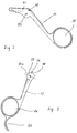
Das in Figur 1 dargestellte Instrument besteht aus einem langgestreckten Rohr 10, an dem die stationären Teile des Instrumentes, nämlich eine feststehende Schneide 22 und ein feststehender Schenkel 14, an einander gegenüberliegenden Enden auf noch näher zu beschreibende Weise befestigt sind. Es ist ein zweiter, bewegbarer Schenkel 12 vorgesehen, der um eine Achse 54 schwenkbar und so gegen den Schenkel 14 bewegbar ist. Beide Schenkel 12, 14 weisen an ihren Enden jeweils ein Auge 16, 18 auf, wobei in das Auge 18 des feststehenden Schenkels 14 üblicherweise der Daumen eines Benutzers eingreift, in das Auge 16 des bewegbaren Schenkels 12 der Zeigefinger, gegebenenfalls auch der Mittelfinger. Am Auge 16 ist ein Stützansatz 20 vorgesehen, der in Richtung auf den Schenkel 14 gekrümmt ist, so daß sich eine Anlagefläche für einen weiteren Finger des Benutzers ergibt. Dieser kann somit die Öffenbewegung der Schenkel 12, 14 gegeneinander unterstützen. An dem dem Auge 16 gegenüberliegenden Ende des Schenkels 12 ist ein Lagerelement 50 vorgesehen, durch das im wesentlichen zentral die Achse 54 geführt ist. Das Lagerelement 50 ist zwischen zwei Scheiben aus reibungsminderndem Material eingebettet, von denen in der Figur lediglich eine Scheibe 52 dargestellt ist. Als Material ist beispielsweise Polytetrafluoräthylen geeignet. Somit sind keine besonderen Reibungskräfte bei der Bewegung der Schenkel 12, 14 gegeneinander zu überwinden und ein Benutzer wird ein besseres Gefühl für die Führung der Schneidbewegung haben. Ferner ist im Kantenbereich des Lagerelementes 50 eine Ausnehmung oder Aussparung 58 vorgesehen, in die ein am Schenkel 14 vorgesehener Anschlagstift 60 eingreift. Durch geeignet gewählte Abmessungen der Ausnehmung 58 kann der Öffnungswinkel bzw. der Schließwinkel der Schenkel 12, 14 eingestellt werden, als Folge davon auch der jeweils entsprechende Winkel zwischen zwei Schneiden 22, 24. Es wird damit einerseits verhindert, daß sich die Schneiden zu weit öffnen, andererseits wird der übermäßigen Belastung eines eine Anlenkachse 56 bildenden Scherstiftes vorgebeugt. Weiterhin ist am Lagerelement 50 eine Übertragungsstange 30 angelenkt, welche in dem langgestreckten Rohr 10 hin- und herbewegbar ist. Die Anlenkung erfolgt über ein im Zusammenhang mit Figur 7 noch genauer zu beschreibendes Anschlußstück 34. Der gesamte Lagerbereich ist von einem Lagergehäuse 40 eingeschlossen, welches hier allerdings teilweise aufgerissen dargestellt ist, wobei die Verbindung des Lagergehäuses 40 zu dem langgestreckten Rohr 10 über eine Schweiß-, Löt- oder Klebverbindung 44 vorgenommen ist. Diese Verbindung kann auch realisiert werden, indem am Innenrohr 10 ein Außengewinde und am Lagergehäuse 40 ein entsprechendes Innengewinde angebracht werden, so daß die beiden Teile miteinander verschraubt werden können. Eine Sicherung der Verbindung erfolgt durch Zugabe eines Spezialklebstoffes.The instrument shown in Figure 1 consists of an
Wie in dem aufgerissenen Abschnitt des langgestreckten Rohres 10 erkennbar ist, ist die Übertragungsstange 30 von einer Buchse 36 aus reibungsmindernden Material, wiederum beispielsweise Polytetrafluoräthylen, umgeben, so daß sie ebenfalls bewegt werden kann, ohne daß ein größerer Reibungswiderstand zu überwinden wäre. Die Übertragungsstange 30 selbst besteht aus rostfreiem Stahl.As can be seen in the torn section of the
Am distalen Ende des langgestreckten Rohres 10, d. h. an dem Ende, das dem Lagerelement 50 gegenüberliegt, ist die feststehende Schneide 22 mittels einer Schweiß- oder Lötverbindung 42 festgelegt. Auch hier ist eine Klebeverbindung möglich. Die Schneide 22 hat eine sehr geringe Profilhöhe von etwa 1 mm, so daß ein einfacheres Positionieren auch bei festem Gewebe möglich ist. Die bewegbare Schneide 24 ist gegenüber der Schneide 22 um eine Achse 26 verschwenkbar. Über ein Ansatzstück 32 ist die Übertragungsstange 30 weiterhin an der bewegbaren Schneide 24 angelenkt, wobei die Anlenkung mittels eines Stiftes 28 erfolgt. Das Ansatzstück 32 begrenzt, wegen seiner Formgebung mit der geraden vorderen Abschlußkante, die über eine Krümmung in eine oberhalb der Achse 26 verlaufende untere Abschlußkante übergeht, das Schließen der Schneiden 22, 24 über die Unterseite der Schneide 22 hinaus.At the distal end of the
Die Figur 1 stellt die Öffnungsstellung der Schenkel 12, 14 dar. Der Anschlagsstift 60 liegt nahezu an einer Kante der Ausnehmung 58 an. Diese Öffnungsstellung entspricht der Öffnungsstellung der Schneiden 22, 24. Wenn jetzt die Schenkel 12, 14 geschlossen werden, bewegt sich das Lagerelement 50 mit der Ausnehmung 58 gegen den Uhrzeigersinn, bis der Anschlagstift 60 an die der ersten Kante gegenüberliegende zweite Kante der Ausnehmung 58 anschlägt. Dabei wird auf die Übertragungsstange 30 eine Druckkraft ausgeübt, welche die Schließbewegung der Schneiden 22, 24 insbesondere der bewegbaren Schneide 24 bewirkt.FIG. 1 shows the open position of the
Die Achse 54 liegt unterhalb der Achse 56 für die Übertragungsstange 30, um dieser eine Vorschubbewegung für das Schneiden aufzuzwingen.The
Figur 2 zeigt eine Detaildarstellung des feststehenden Schenkels 14. An einem seiner Enden ist, einstückig mit dem Schenkel 14 ausgebildet, das im wesentlichen elliptische Auge 18 angeformt. Am anderen Ende des Schenkels 14 ist ein Verbindungsteil 62 vorgesehen, auf dem einerseits der Anschlagsstift 60 angeordnet ist, andererseits der Stift 54, der die Achse für die Schwenkbewegung der beiden Schenkel des Instrumentes gegeneinander bildet. Die gegenseitige Lage der Stifte 54, 60 ist so gewählt, daß insbesondere der Anschlagsstift 60 seine Funktion im Wirkzusammenhang mit dem in Figur 2 nicht dargestellten Lagerelement ausüben kann. Das Verbindungsteil 62 ist weiterhin so ausgeformt, daß das langgestreckte Rohr bzw. ein Lagergehäuse daran festgelegt werden kann.FIG. 2 shows a detailed representation of the
Figur 3 zeigt eine Detaildarstellung des bewegbaren Schenkels 12. Wiederum ist an einem seiner Enden das im wesentlichen elliptische Auge 16 angeformt. Etwa in der Verlängerung des Schenkels 12 ist an dem Auge 16 der Stützansatz 20 ausgebildet, dessen Krümmung so gewählt ist, daß ein Finger des Benutzers in dieser Krümmung an dem Stützanschlag 20 anliegen kann. An dem dem Auge 16 gegenüberliegenden Ende des Schenkels 12 ist das Lagerelement 50 vorgesehen, welches nahezu kreisförmig ausgestaltet ist und zentral eine Öffnung 54a aufweist, welche in bezug auf das Lagerelement 50 die Schwenkachse für die Bewegung der beiden Schenkel gegeneinander definiert. An der von dem Schenkel 12 abgewandten Seite des Lagerelementes 15 ist dieses etwas verlängert ausgebildet und weist eine Ausnehmung 58 mit dem wesentlichen U-förmigen Schnitt auf. Benachbart der Ausnehmung 58 ist der Anlenkpunkt 56 für die Übertragungsstange vorgesehen.FIG. 3 shows a detailed representation of the
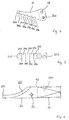
Figur 4 zeigt in Vergrößerung eine Seitenansicht der bewegbaren Schneide 24. Diese ist in ihrem oberen Bereich, also and der Kante, die der feststehenden Schneide abgewandt ist, leicht bogenförmig gekrümmt, der eigentliche Schneidbereich besteht aus fünf Teilbereichen 242, 246, 250, 254, 258, im allgemeinen haben sich vier bis sechs Teilbereiche als günstig erwiesen, die jeweils durch voneinander beabstandete, auch schneidende Zähne 244, 248, 252, 256 voneinander getrennt sind. Auch der Frontbereich der Schneide 24 ist als Zahn 240 ausgebildet. Während sich dieser Zahn 240 allerdings im wesentlichen senkrecht zur Schneidfläche der Schneide 24 erstreckt, sind die Zähne 244, 248, 252, 256 leicht nach hinten, also in Richtung auf die Achse der Schwenkbewegung der Schneiden relativ zueinander, gerichtet. Damit wird erreicht, daß bei der Schneidbewegung die Zähne sukzessiv, beginnend mit dem Zahn 256, das Gewebe in dem zu schneidenden Bereich halten, während der eigentliche Schnitt nacheinander in den Teilbereichen 258, 254, 250, 246, 242 ausgeführt wird. Außerhalb des Bereiches der Einzelschneiden befindet sich eine Öffnung 26a, die für die Schneide 24 die Achse für die Schwenkbewegung definiert, sowie der Anlenkpunkt für die Übertragungsstange, gebildet durch einen durch eine Öffnung geführten Stift 28.FIG. 4 shows an enlarged side view of the
In Figur 5 ist besonders deutlich zu erkennen, welche Maßnahmen für das Festlegen der Übertragungsstange getroffen sind, nämlich eine stufenförmige Ausnehmung 260, auf deren Stufe die Übertragungsstange aufliegen kann. Ebenso ist der gekrümmt verlaufende Frontbereich der Schneide mit dem Zahn 240 deutlich dargestellt. Die Zähne 244, 248, 252, 256 erstrecken sich über die gesamte Breite der Schneide.FIG. 5 shows particularly clearly what measures have been taken to fix the transmission rod, namely a step-shaped
Figur 6 zeigt die feststehende Schneide 22 in vergrößerter Darstellung, welche einen Ansatzkeil 220 aufweist, der so ausgelegt ist, daß er in das langgestreckte Rohr 10 eingeführt werden kann, wobei dieses dann mittels einer Schweiß-, Löt- oder Klebverbindung 42 fest mit der Schneide 22 verbunden wird. Vor der Schweiß-, Löt- oder Klebverbindung 42 befindet sich die Achse 26 für die Schwenkbewegung der Schneiden relativ zueinander. Bei der feststehenden Schneide 22 ist eine einheitliche Schneidfläche 222 vorgesehen, welche einen gekrümmten Verlauf hat und sich über die gesamte Höhe der Schneide 22 erstreckt und in einer abgerundeten Front 224 mündet.FIG. 6 shows the fixed
Im Querschnitt ist die Schneide 22 quadratisch oder rechteckförmig, was die Stabilität begünstigt und auch einen einfacheren Zusammenbau erlaubt.In cross section, the
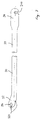
Figur 7 zeigt eine Seitenansicht der Übertragungsstange 30 in teilweise gebrochener Darstellung. Ein im wesentlicher langgestreckter Abschnitt weist an seinen Enden 32, 34 Anschlußstücke auf, die jeweils das distale bzw. proximale Ende der Übertragungsstange 30 bewegen. Am proximalen Ende, also am Anschlußstück 34, ist ein vertikaler Schlitz 340 vorgesehen, der sich vom Kantenbereich des Anschlußstückes 34 her in dessen vorderen Bereich bis etwa zum Zentrum hin erstreckt. Diese Ausnehmung wird nach Art eines Hakens auf einen Stift gehängt, der am Anlenkpunkt der Übertragungsstange 30 am Lagerelement vorgesehen ist, was einen einfachen und schnellen Zusammenbau ermöglicht. Am distalen Ende der Übertragungsstange 30, also am Anschlußstück 32, welches leicht abgewinkelt vom langgestreckten Abschnitt der Übertragungsstange 30 verläuft, ist eine Öffnung 28a ausgebildet, durch die ein Stift für die Anlenkung der Übertragungsstange 30 an der bewegbaren Schneide geführt werden kann. Am unteren Teil befindet sich eine Ausnehmung 320, welche auf die im Zusammenhang mit Figur 5 beschriebenen Stufe der dort dargestellten Ausnehmung gesetzt wird.FIG. 7 shows a side view of the
Der schwächste Teil des Instrumentes ist zweifelsohne der Stift, der die Achse 56 bildet. Dieser sollte so groß wie möglich dimensioniert werden, um Bruch weitgehendst auszuschalten. Insgesamt ist aber zu erwarten, daß beispielsweise wegen der quadratischen bzw. rechteckförmigen Ausgestaltung der Schneide 22, der nachgiebigen Übertragungsstange 30 und den entsprechend ausgelegten Verbindungen 42, 44 ein stabiles, unanfälliges Instrument vorliegt.The weakest part of the instrument is undoubtedly the pin that forms
Das in der Figur 8 dargestellte Instrument entspricht in seiner Schließ- und Öffenmechanik dem der Figur 1, jedoch ist, da es als Faß- oder Greifzange verwendet werden soll, am vorderen Ende der Übertragungsstange 30 eine noch genauer zu beschreibende Greifeinrichtung 80, 82 vorgesehen, ferner weist es eine Verriegelungseinrichtung 70 auf, mittels derer die Schenkel 12, 14 in einer bestimmten Position relativ zueinander gehalten werden können.The instrument shown in FIG. 8 corresponds in its closing and opening mechanism to that of FIG. 1, but since it is to be used as gripping or gripping pliers, a gripping
Die Verriegelungseinrichtung 70 besteht aus einem Arm 72, der kreisbogenförmig gekrümmt und so bemessen ist, daß sein Bogen mindestens den maximalen Öffnungswinkel der Schenkel 12, 14 überstreicht. Der Arm 72 ist an einem seiner Enden an einem Anlenkpunkt 78 am Schenkel 12 schwenkbar angebracht, wobei die Schwenkbewegung mit einem Betätigungshebel 76 durchgeführt wird, der entsprechend der Krümmung des Auges 16 an der an den Schenkel 12 anschließenden Seite und des Stützansatzes 20 geformt ist. Das zweite Ende des Armes 72 ist durch eine Durchgangsöffnung 92 im Schenkel 14 geführt, in der auch eine Klinkenvorrichtung 90 untergebracht ist. Diese weist, dem Arm 72 zugewandt, eine Zahnung auf, die über die Betätigung des Betätigungshebels 76 mit einer Zahnung 74 auf dem Arm 72 in Eingriff bringbar ist. Im Zahnungseingriff ist die Position der Schenkel 12, 14 zueinander fixiert.The locking
Figur 9 zeigt den Schenkel 14 im Detail. Die Durchgangsöffnung 92 ist in der Nähe des Auges 18 vorgesehen. Die Klinkenvorrichtung wird darin durch Stifte oder dergleichen fixiert, die durch Bohrungen 94, 96 in den die Durchgangsöffnung 92 begrenzenden Wänden vorgesehen sind.Figure 9 shows the
Figur 10 zeigt die Lage des Anlenkpunktes 78 am Schenkel 12. In der Nähe des Auges 16, auf der dem zweiten Schenkel 14 zugewandten Seite, ist eine Ausnehmung 79 mit etwa halbovalem Querschnitt vorgesehen, in die der Anlenkpunkt 76 gelegt ist.FIG. 10 shows the position of the
Figur 11 zeigt die Verriegelungseinrichtung 70. Im Übergangsbereich zwischen dem Arm 72 und dem Betätigungshebel 76 ist sie etwa dreieckförmig verbreitert, wobei der Anlenkpunkt 78 an der freien Spitze dieses Dreieckes liegt. Der Arm 72 trägt die Zahnung 74 an einem Endabschnitt, der etwa die Hälfte bis ein Drittel der Länge des Armes 72 beträgt.FIG. 11 shows the
Figur 12 zeigt das Ende des Armes 72 mit einem Teil der Zahnung 74. Die Zähne der Zahnung haben abgerundete Spitzen und steil abfallende Flanken auf der dem abgerundeten Ende des Armes 72 abgewandten Seite, flacher abfallende Flanken auf der zugewandten Seite.FIG. 12 shows the end of the
In der Figur 13 ist die Klinkenvorrichtung 90 im wesentlichen quaderförmig ausgebildet und trägt an einer ihrer kürzeren Seiten eine Zahnung 98, die in ihrer Formgebung an die zahnung des Armes angepaßt ist, so daß sich zwischen den beiden Zahnungen ein formschlüssiger Eingriff ergibt. Bohrungen 94', 96' sind an Stellen vorgesehen, die denen der Bohrungen 94, 96 der Figur 8 entsprechen.In Figure 13, the
Figur 14 zeigt eine Greifbacke 80 der Greifeinrichtung, die am Instrument ebenso befestigt wird wie die obere Schneide der Figur 4. Zum Greifen ist eine "stumpfe" Zahnung 84 an der Unterseite der Greifbacke 80 angebracht, wobei die Zahnung 84, wie Figur 15 zeigt, in hintereinanderliegenden kreisförmigen Abschnitten 85, 85', 85'' mit von der Spitze her zunehmendem Durchmesser ausgebildet ist.FIG. 14 shows a
Entsprechend ausgestaltet ist das Gegenstück 82 der Figuren 16 und 17, das die Zahnung 86 in kreisförmigen Abschnitten 87, 87', 87'' ausgebildet hat, wieder hintereinanderliegend und mit von der Spitze her zunehmenden Durchmessern.The
Die in der vorstehenden Beschreibung, in der Zeichnung sowie in den Ansprüchen offenbarten Merkmale der Erfindung können sowohl einzeln als auch in beliebigen Kombinationen für die Verwirklichung der Erfindung in ihren verschiedenen Ausführungsformen wesentlich sein.


Claims (16)
Applications Claiming Priority (4)
| Application Number | Priority Date | Filing Date | Title |
|---|---|---|---|
| DE4224226 | 1992-07-22 | ||
| DE4224226 | 1992-07-22 | ||
| DE4235023 | 1992-07-22 | ||
| DE4235023A DE4235023A1 (en) | 1992-07-22 | 1992-10-16 | Gripping and / or cutting instrument for endoscopic purposes |
Publications (2)
| Publication Number | Publication Date |
|---|---|
| EP0594946A1 true EP0594946A1 (en) | 1994-05-04 |
| EP0594946B1 EP0594946B1 (en) | 1996-09-11 |
Family
ID=25916851
Family Applications (1)
| Application Number | Title | Priority Date | Filing Date |
|---|---|---|---|
| EP93110327A Expired - Lifetime EP0594946B1 (en) | 1992-07-22 | 1993-06-29 | Gripping and/or cutting device for endoscopic surgery |
Country Status (5)
| Country | Link |
|---|---|
| US (1) | US5613977A (en) |
| EP (1) | EP0594946B1 (en) |
| AT (1) | ATE142456T1 (en) |
| DE (2) | DE4235023A1 (en) |
| ES (1) | ES2091524T3 (en) |
Cited By (3)
| Publication number | Priority date | Publication date | Assignee | Title |
|---|---|---|---|---|
| DE19742112A1 (en) * | 1997-09-24 | 1999-03-25 | Raible Cnc Technik | Surgical slide shaft instrument for cutting |
| AU717023B2 (en) * | 1996-06-21 | 2000-03-16 | Ethicon Endo-Surgery, Inc. | Variable position handle locking mechanism |
| DE10049614A1 (en) * | 2000-10-05 | 2002-04-11 | Weba Medizinmechanik Gmbh & Co | Surgical bone stamp has mounting, slide-bar, two handle parts, and plastic slide layer |
Families Citing this family (33)
| Publication number | Priority date | Publication date | Assignee | Title |
|---|---|---|---|---|
| DE19652821C1 (en) | 1996-12-18 | 1998-04-23 | Gottfried Hipp | Wear and corrosion resistant low friction medical scissors |
| US5921996A (en) * | 1997-05-02 | 1999-07-13 | Cardio Thoracic Systems, Inc. | Surgical clamp applier/remover and detachable clamp |
| DE10207207A1 (en) * | 2002-02-21 | 2003-09-25 | Storz Karl Gmbh & Co Kg | Medical instrument |
| US7879046B2 (en) * | 2001-10-01 | 2011-02-01 | Depuy Mitek, Inc. | Suturing apparatus and method |
| US6991633B2 (en) * | 2001-10-10 | 2006-01-31 | Codman & Shurtleff, Inc. | Rongeur with detachable crossbar |
| US6638280B2 (en) * | 2001-10-10 | 2003-10-28 | Codman & Shurtleff, Inc. | Rongeur with drainage |
| US6685710B2 (en) | 2001-10-10 | 2004-02-03 | Codman & Shurtleff, Inc. | Rongeur with detachable crossbar |
| DE10305584A1 (en) * | 2002-02-04 | 2003-08-07 | Arthrex Inc | Endoscopic instrument, provided with gripping device suitable for gripping surgical thread and precise positioning of knot |
| US7410494B2 (en) | 2003-06-20 | 2008-08-12 | International And Surgical Innovations, Llc | Device for grasping and/or severing |
| US7727256B2 (en) * | 2004-09-24 | 2010-06-01 | Arthrex, Inc. | Grasper assembly |
| US9078650B2 (en) * | 2005-11-23 | 2015-07-14 | Arthrex, Inc. | Handle system for suture driving device |
| US7655004B2 (en) | 2007-02-15 | 2010-02-02 | Ethicon Endo-Surgery, Inc. | Electroporation ablation apparatus, system, and method |
| US20090182332A1 (en) * | 2008-01-15 | 2009-07-16 | Ethicon Endo-Surgery, Inc. | In-line electrosurgical forceps |
| US8398673B2 (en) * | 2008-02-15 | 2013-03-19 | Surgical Innovations V.O.F. | Surgical instrument for grasping and cutting tissue |
| US8888792B2 (en) | 2008-07-14 | 2014-11-18 | Ethicon Endo-Surgery, Inc. | Tissue apposition clip application devices and methods |
| BRPI0804432A2 (en) * | 2008-10-20 | 2010-07-13 | Imbros Administracao E Partici | tweezers for laparoscopic procedures |
| US8157834B2 (en) | 2008-11-25 | 2012-04-17 | Ethicon Endo-Surgery, Inc. | Rotational coupling device for surgical instrument with flexible actuators |
| US8361066B2 (en) | 2009-01-12 | 2013-01-29 | Ethicon Endo-Surgery, Inc. | Electrical ablation devices |
| CA2759297C (en) * | 2009-03-23 | 2015-08-04 | Linvatec Corporation | Suture passing apparatus and method |
| US20110098704A1 (en) | 2009-10-28 | 2011-04-28 | Ethicon Endo-Surgery, Inc. | Electrical ablation devices |
| US9028483B2 (en) | 2009-12-18 | 2015-05-12 | Ethicon Endo-Surgery, Inc. | Surgical instrument comprising an electrode |
| US9254169B2 (en) | 2011-02-28 | 2016-02-09 | Ethicon Endo-Surgery, Inc. | Electrical ablation devices and methods |
| US9233241B2 (en) | 2011-02-28 | 2016-01-12 | Ethicon Endo-Surgery, Inc. | Electrical ablation devices and methods |
| WO2012125785A1 (en) | 2011-03-17 | 2012-09-20 | Ethicon Endo-Surgery, Inc. | Hand held surgical device for manipulating an internal magnet assembly within a patient |
| US9427255B2 (en) | 2012-05-14 | 2016-08-30 | Ethicon Endo-Surgery, Inc. | Apparatus for introducing a steerable camera assembly into a patient |
| US9078662B2 (en) | 2012-07-03 | 2015-07-14 | Ethicon Endo-Surgery, Inc. | Endoscopic cap electrode and method for using the same |
| US9545290B2 (en) | 2012-07-30 | 2017-01-17 | Ethicon Endo-Surgery, Inc. | Needle probe guide |
| US10314649B2 (en) | 2012-08-02 | 2019-06-11 | Ethicon Endo-Surgery, Inc. | Flexible expandable electrode and method of intraluminal delivery of pulsed power |
| US9572623B2 (en) | 2012-08-02 | 2017-02-21 | Ethicon Endo-Surgery, Inc. | Reusable electrode and disposable sheath |
| US9277957B2 (en) | 2012-08-15 | 2016-03-08 | Ethicon Endo-Surgery, Inc. | Electrosurgical devices and methods |
| US10098527B2 (en) | 2013-02-27 | 2018-10-16 | Ethidcon Endo-Surgery, Inc. | System for performing a minimally invasive surgical procedure |
| US10080562B2 (en) | 2015-08-06 | 2018-09-25 | DePuy Synthes Products, Inc. | Methods, systems, and devices for surgical suturing |
| US9439647B1 (en) | 2016-03-02 | 2016-09-13 | Arthrogenx, LLC. | Suture passing instruments and methods |
Citations (5)
| Publication number | Priority date | Publication date | Assignee | Title |
|---|---|---|---|---|
| US4369788A (en) * | 1980-01-31 | 1983-01-25 | Goald Harold J | Reversed forceps for microdisc surgery |
| EP0119405A1 (en) * | 1983-01-26 | 1984-09-26 | Dyonics, Inc. | Surgical instrument for cutting fragments of cartilage and other tissue |
| US4813407A (en) * | 1986-07-30 | 1989-03-21 | Vogen Kenneth W | Sesamoid bone clamp |
| EP0313820A2 (en) * | 1987-10-26 | 1989-05-03 | Richard Wolf GmbH | Forceps, in particular claw-shaped cutters |
| EP0484671A2 (en) * | 1990-10-05 | 1992-05-13 | United States Surgical Corporation | Endoscopic surgical instrument |
Family Cites Families (18)
| Publication number | Priority date | Publication date | Assignee | Title |
|---|---|---|---|---|
| DE356185C (en) * | 1920-12-09 | 1922-07-18 | Ernst Bacher | Surgical instrument |
| DE827927C (en) * | 1945-02-19 | 1952-01-14 | Waldes Kohinoor Inc | Pliers for installing and removing slotted lock washers |
| US3515139A (en) * | 1966-08-29 | 1970-06-02 | Codman & Shurtleff | Atraumatic clamp |
| US3585985A (en) * | 1968-12-16 | 1971-06-22 | Wilbur J Gould | Surgical instrument for biopsy |
| US3814102A (en) * | 1972-10-12 | 1974-06-04 | B Thal | Surgical instrument |
| US4201213A (en) * | 1978-01-30 | 1980-05-06 | Codman & Shurtleff, Inc. | Surgical tool |
| DE3215949A1 (en) * | 1982-04-29 | 1983-11-03 | Storz, Karl, 7200 Tuttlingen | SURGICAL PLIERS |
| US4478532A (en) * | 1982-05-26 | 1984-10-23 | Microdent Industries | Box joint employing screw pivot pin for adjustable tightening |
| DE8316034U1 (en) * | 1983-06-01 | 1983-09-29 | Richard Wolf Gmbh, 7134 Knittlingen | Scissor handle for exchangeable pliers bits |
| US4919152A (en) * | 1987-03-02 | 1990-04-24 | Ralph Ger | Method of closing the opening of a hernial sac |
| DD233302A1 (en) * | 1984-12-28 | 1986-02-26 | Univ Berlin Humboldt | SAFETY BIOPSY FORCEPS |
| US4674501A (en) * | 1986-04-14 | 1987-06-23 | Greenberg I Melbourne | Surgical instrument |
| US4950273A (en) * | 1987-10-26 | 1990-08-21 | Briggs Jeffrey M | Cable action instrument |
| US4890615B1 (en) * | 1987-11-05 | 1993-11-16 | Linvatec Corporation | Arthroscopic suturing instrument |
| US4896661A (en) * | 1988-02-05 | 1990-01-30 | Pfizer, Inc. | Multi purpose orthopedic ratcheting forceps |
| US5219357A (en) * | 1990-05-31 | 1993-06-15 | Tnco, Inc. | Micro-instrument |
| US5489292A (en) * | 1990-10-05 | 1996-02-06 | United States Surgical Corporation | Endoscopic surgical instrument with grip enhancing means |
| US5366477A (en) * | 1991-10-17 | 1994-11-22 | American Cyanamid Company | Actuating forces transmission link and assembly for use in surgical instruments |
-
1992
- 1992-10-16 DE DE4235023A patent/DE4235023A1/en not_active Withdrawn
-
1993
- 1993-06-29 AT AT93110327T patent/ATE142456T1/en not_active IP Right Cessation
- 1993-06-29 ES ES93110327T patent/ES2091524T3/en not_active Expired - Lifetime
- 1993-06-29 DE DE59303738T patent/DE59303738D1/en not_active Expired - Lifetime
- 1993-06-29 EP EP93110327A patent/EP0594946B1/en not_active Expired - Lifetime
-
1995
- 1995-05-17 US US08/442,767 patent/US5613977A/en not_active Expired - Lifetime
Patent Citations (5)
| Publication number | Priority date | Publication date | Assignee | Title |
|---|---|---|---|---|
| US4369788A (en) * | 1980-01-31 | 1983-01-25 | Goald Harold J | Reversed forceps for microdisc surgery |
| EP0119405A1 (en) * | 1983-01-26 | 1984-09-26 | Dyonics, Inc. | Surgical instrument for cutting fragments of cartilage and other tissue |
| US4813407A (en) * | 1986-07-30 | 1989-03-21 | Vogen Kenneth W | Sesamoid bone clamp |
| EP0313820A2 (en) * | 1987-10-26 | 1989-05-03 | Richard Wolf GmbH | Forceps, in particular claw-shaped cutters |
| EP0484671A2 (en) * | 1990-10-05 | 1992-05-13 | United States Surgical Corporation | Endoscopic surgical instrument |
Cited By (3)
| Publication number | Priority date | Publication date | Assignee | Title |
|---|---|---|---|---|
| AU717023B2 (en) * | 1996-06-21 | 2000-03-16 | Ethicon Endo-Surgery, Inc. | Variable position handle locking mechanism |
| DE19742112A1 (en) * | 1997-09-24 | 1999-03-25 | Raible Cnc Technik | Surgical slide shaft instrument for cutting |
| DE10049614A1 (en) * | 2000-10-05 | 2002-04-11 | Weba Medizinmechanik Gmbh & Co | Surgical bone stamp has mounting, slide-bar, two handle parts, and plastic slide layer |
Also Published As
| Publication number | Publication date |
|---|---|
| DE4235023A1 (en) | 1994-01-27 |
| ES2091524T3 (en) | 1996-11-01 |
| US5613977A (en) | 1997-03-25 |
| DE59303738D1 (en) | 1996-10-17 |
| ATE142456T1 (en) | 1996-09-15 |
| EP0594946B1 (en) | 1996-09-11 |
Similar Documents
| Publication | Publication Date | Title |
|---|---|---|
| EP0594946B1 (en) | Gripping and/or cutting device for endoscopic surgery | |
| DE19704580C2 (en) | Surgical thread cutter | |
| EP1784137B1 (en) | Surgical instrument | |
| DE3344213C2 (en) | ||
| DE69530454T2 (en) | Endoscopic vascular suturing device | |
| DE19521257C2 (en) | Surgical forceps | |
| DE10102089C1 (en) | Surgical instrument | |
| DE69630093T2 (en) | Improved locking mechanism for surgical instruments | |
| DE3741879A1 (en) | ENDOSCOPIC INSTRUMENT | |
| EP0513471A2 (en) | Surgical instrument | |
| DE4323809A1 (en) | Surgical instrument with pair of circular grip parts - has pair of relatively movable working elements at distal end, and actuator | |
| DE10110106A1 (en) | Surgical forceps | |
| EP1584293A1 (en) | Laparoscopic instrument | |
| DE102010040667A1 (en) | Instrument for endoscopic surgery | |
| EP1629785B1 (en) | Medical forceps | |
| DE10136964A1 (en) | Surgical instrument | |
| EP2814406B1 (en) | Device for applying a surgical clip | |
| EP2545857B1 (en) | Medical cutting instrument for cutting muscles and tendons | |
| EP3773241A1 (en) | Medical instrument | |
| DE3921935A1 (en) | Surgical instrument | |
| DE102007030874B4 (en) | Surgical instrument | |
| EP1414357B1 (en) | Medical grasping and holding instrument | |
| EP1587434A1 (en) | Medical instrument for dissecting tissue | |
| DE4223162A1 (en) | Gripper for surgical instruments with two clamping jaws - has gripping jaw inner faces shaped in closed position such as to produce milled surface | |
| DE102013005874A1 (en) | Handle for a surgical instrument |
Legal Events
| Date | Code | Title | Description |
|---|---|---|---|
| PUAI | Public reference made under article 153(3) epc to a published international application that has entered the european phase |
Free format text: ORIGINAL CODE: 0009012 |
|
| AK | Designated contracting states |
Kind code of ref document: A1 Designated state(s): AT BE CH DE ES FR GB IT LI NL SE |
|
| 17P | Request for examination filed |
Effective date: 19941006 |
|
| 17Q | First examination report despatched |
Effective date: 19950314 |
|
| GRAH | Despatch of communication of intention to grant a patent |
Free format text: ORIGINAL CODE: EPIDOS IGRA |
|
| GRAH | Despatch of communication of intention to grant a patent |
Free format text: ORIGINAL CODE: EPIDOS IGRA |
|
| GRAA | (expected) grant |
Free format text: ORIGINAL CODE: 0009210 |
|
| AK | Designated contracting states |
Kind code of ref document: B1 Designated state(s): AT BE CH DE ES FR GB IT LI NL SE |
|
| REF | Corresponds to: |
Ref document number: 142456 Country of ref document: AT Date of ref document: 19960915 Kind code of ref document: T |
|
| REG | Reference to a national code |
Ref country code: CH Ref legal event code: NV Representative=s name: BUECHEL & PARTNER AG PATENTBUERO |
|
| ET | Fr: translation filed | ||
| GBT | Gb: translation of ep patent filed (gb section 77(6)(a)/1977) |
Effective date: 19960913 |
|
| ITF | It: translation for a ep patent filed |
Owner name: FUMERO BREVETTI S.N.C. |
|
| REF | Corresponds to: |
Ref document number: 59303738 Country of ref document: DE Date of ref document: 19961017 |
|
| REG | Reference to a national code |
Ref country code: ES Ref legal event code: FG2A Ref document number: 2091524 Country of ref document: ES Kind code of ref document: T3 |
|
| PLBE | No opposition filed within time limit |
Free format text: ORIGINAL CODE: 0009261 |
|
| STAA | Information on the status of an ep patent application or granted ep patent |
Free format text: STATUS: NO OPPOSITION FILED WITHIN TIME LIMIT |
|
| 26N | No opposition filed | ||
| REG | Reference to a national code |
Ref country code: CH Ref legal event code: PUE Owner name: FRIATEC AG TRANSFER- SULZER ORTHOPAEDIE AG Ref country code: CH Ref legal event code: NV Representative=s name: SULZER MANAGEMENT AG |
|
| REG | Reference to a national code |
Ref country code: FR Ref legal event code: TP |
|
| REG | Reference to a national code |
Ref country code: GB Ref legal event code: 732E |
|
| NLS | Nl: assignments of ep-patents |
Owner name: SULZER ORTHOPAEDIE AG |
|
| REG | Reference to a national code |
Ref country code: ES Ref legal event code: PC2A |
|
| REG | Reference to a national code |
Ref country code: GB Ref legal event code: IF02 |
|
| REG | Reference to a national code |
Ref country code: GB Ref legal event code: 732E |
|
| REG | Reference to a national code |
Ref country code: CH Ref legal event code: PUE Owner name: ZIMMER GMBH Free format text: SULZER ORTHOPAEDIE AG#GRABENSTRASSE 25#6341 BAAR (CH) -TRANSFER TO- ZIMMER GMBH#SULZER ALLEE 8#8404 WINTERTHUR (CH) |
|
| NLS | Nl: assignments of ep-patents |
Owner name: ZIMMER GMBH Effective date: 20061010 |
|
| NLT1 | Nl: modifications of names registered in virtue of documents presented to the patent office pursuant to art. 16 a, paragraph 1 |
Owner name: CENTERPULSE ORTHOPEDICS LTD. |
|
| REG | Reference to a national code |
Ref country code: FR Ref legal event code: TP Ref country code: FR Ref legal event code: CD Ref country code: FR Ref legal event code: CA |
|
| BECA | Be: change of holder's address |
Owner name: *ZIMMER G.M.B.H.SULZER ALLEE 8, CH-8404 WINTERTHUR Effective date: 20060802 |
|
| BECN | Be: change of holder's name |
Owner name: *ZIMMER G.M.B.H. Effective date: 20060802 |
|
| PGFP | Annual fee paid to national office [announced via postgrant information from national office to epo] |
Ref country code: AT Payment date: 20080603 Year of fee payment: 16 |
|
| PGFP | Annual fee paid to national office [announced via postgrant information from national office to epo] |
Ref country code: NL Payment date: 20080624 Year of fee payment: 16 |
|
| PGFP | Annual fee paid to national office [announced via postgrant information from national office to epo] |
Ref country code: SE Payment date: 20090629 Year of fee payment: 17 |
|
| PGFP | Annual fee paid to national office [announced via postgrant information from national office to epo] |
Ref country code: BE Payment date: 20090715 Year of fee payment: 17 |
|
| NLV4 | Nl: lapsed or anulled due to non-payment of the annual fee |
Effective date: 20100101 |
|
| PG25 | Lapsed in a contracting state [announced via postgrant information from national office to epo] |
Ref country code: AT Free format text: LAPSE BECAUSE OF NON-PAYMENT OF DUE FEES Effective date: 20090629 |
|
| PG25 | Lapsed in a contracting state [announced via postgrant information from national office to epo] |
Ref country code: NL Free format text: LAPSE BECAUSE OF NON-PAYMENT OF DUE FEES Effective date: 20100101 |
|
| PGFP | Annual fee paid to national office [announced via postgrant information from national office to epo] |
Ref country code: FR Payment date: 20100617 Year of fee payment: 18 Ref country code: ES Payment date: 20100615 Year of fee payment: 18 |
|
| PGFP | Annual fee paid to national office [announced via postgrant information from national office to epo] |
Ref country code: IT Payment date: 20100621 Year of fee payment: 18 |
|
| PGFP | Annual fee paid to national office [announced via postgrant information from national office to epo] |
Ref country code: CH Payment date: 20100430 Year of fee payment: 18 |
|
| PGFP | Annual fee paid to national office [announced via postgrant information from national office to epo] |
Ref country code: GB Payment date: 20100401 Year of fee payment: 18 Ref country code: DE Payment date: 20100630 Year of fee payment: 18 |
|
| BERE | Be: lapsed |
Owner name: *ZIMMER G.M.B.H. Effective date: 20100630 |
|
| EUG | Se: european patent has lapsed | ||
| PG25 | Lapsed in a contracting state [announced via postgrant information from national office to epo] |
Ref country code: BE Free format text: LAPSE BECAUSE OF NON-PAYMENT OF DUE FEES Effective date: 20100630 |
|
| REG | Reference to a national code |
Ref country code: CH Ref legal event code: PL |
|
| GBPC | Gb: european patent ceased through non-payment of renewal fee |
Effective date: 20110629 |
|
| PG25 | Lapsed in a contracting state [announced via postgrant information from national office to epo] |
Ref country code: IT Free format text: LAPSE BECAUSE OF NON-PAYMENT OF DUE FEES Effective date: 20110629 |
|
| REG | Reference to a national code |
Ref country code: FR Ref legal event code: ST Effective date: 20120229 |
|
| REG | Reference to a national code |
Ref country code: DE Ref legal event code: R119 Ref document number: 59303738 Country of ref document: DE Effective date: 20120103 |
|
| PG25 | Lapsed in a contracting state [announced via postgrant information from national office to epo] |
Ref country code: LI Free format text: LAPSE BECAUSE OF NON-PAYMENT OF DUE FEES Effective date: 20110630 Ref country code: CH Free format text: LAPSE BECAUSE OF NON-PAYMENT OF DUE FEES Effective date: 20110630 Ref country code: FR Free format text: LAPSE BECAUSE OF NON-PAYMENT OF DUE FEES Effective date: 20110630 Ref country code: DE Free format text: LAPSE BECAUSE OF NON-PAYMENT OF DUE FEES Effective date: 20120103 |
|
| PG25 | Lapsed in a contracting state [announced via postgrant information from national office to epo] |
Ref country code: GB Free format text: LAPSE BECAUSE OF NON-PAYMENT OF DUE FEES Effective date: 20110629 |
|
| PG25 | Lapsed in a contracting state [announced via postgrant information from national office to epo] |
Ref country code: SE Free format text: LAPSE BECAUSE OF NON-PAYMENT OF DUE FEES Effective date: 20100630 |
|
| REG | Reference to a national code |
Ref country code: ES Ref legal event code: FD2A Effective date: 20121207 |
|
| PG25 | Lapsed in a contracting state [announced via postgrant information from national office to epo] |
Ref country code: ES Free format text: LAPSE BECAUSE OF NON-PAYMENT OF DUE FEES Effective date: 20110630 |