EP0594797B1 - Process for monitoring a zone - Google Patents
Process for monitoring a zone Download PDFInfo
- Publication number
- EP0594797B1 EP0594797B1 EP93902244A EP93902244A EP0594797B1 EP 0594797 B1 EP0594797 B1 EP 0594797B1 EP 93902244 A EP93902244 A EP 93902244A EP 93902244 A EP93902244 A EP 93902244A EP 0594797 B1 EP0594797 B1 EP 0594797B1
- Authority
- EP
- European Patent Office
- Prior art keywords
- area
- radar
- points
- point
- cell
- Prior art date
- Legal status (The legal status is an assumption and is not a legal conclusion. Google has not performed a legal analysis and makes no representation as to the accuracy of the status listed.)
- Expired - Lifetime
Links
Images


Classifications
-
- G—PHYSICS
- G01—MEASURING; TESTING
- G01S—RADIO DIRECTION-FINDING; RADIO NAVIGATION; DETERMINING DISTANCE OR VELOCITY BY USE OF RADIO WAVES; LOCATING OR PRESENCE-DETECTING BY USE OF THE REFLECTION OR RERADIATION OF RADIO WAVES; ANALOGOUS ARRANGEMENTS USING OTHER WAVES
- G01S13/00—Systems using the reflection or reradiation of radio waves, e.g. radar systems; Analogous systems using reflection or reradiation of waves whose nature or wavelength is irrelevant or unspecified
- G01S13/87—Combinations of radar systems, e.g. primary radar and secondary radar
-
- G—PHYSICS
- G01—MEASURING; TESTING
- G01S—RADIO DIRECTION-FINDING; RADIO NAVIGATION; DETERMINING DISTANCE OR VELOCITY BY USE OF RADIO WAVES; LOCATING OR PRESENCE-DETECTING BY USE OF THE REFLECTION OR RERADIATION OF RADIO WAVES; ANALOGOUS ARRANGEMENTS USING OTHER WAVES
- G01S13/00—Systems using the reflection or reradiation of radio waves, e.g. radar systems; Analogous systems using reflection or reradiation of waves whose nature or wavelength is irrelevant or unspecified
- G01S13/02—Systems using reflection of radio waves, e.g. primary radar systems; Analogous systems
- G01S13/04—Systems determining presence of a target
Definitions
- the invention relates to a method for monitoring an area according to the preamble of claim 1. Such a method is known from GB-A-2 165 414.
- the invention particularly relates to the surveillance of an area in which at least one non-cooperative (radar) target is present.
- a destination has no so-called transponder and / or no navigation system, the navigation result of which can be queried by a fixed (radar) transmission / reception system.
- Such an area can be, for example, a so-called regional airfield, which is handled according to visual flight rules.
- the area can e.g. B. also be an apron belonging to a major airport, on the z. B. next to the resting or moving aircraft also stationary or moving vehicles, e.g. B. feeder buses and / or supply vehicles must be monitored.
- the area can e.g. B. also a shipping route, e.g. B. a river and / or a canal or a port facility.
- the invention is therefore based on the object of specifying a generic method which enables complete, low-warpage, accurate and, as far as possible, location-independent location, classification and tracking of stationary and / or moving objects (targets) in the area to be monitored.
- the invention is also based on the object of specifying an inexpensive and reliable method.
- a first advantage of the invention consists in the fact that in an area to be monitored, a uniformly accurate and improved location and classification with a combination of high-resolution, inexpensive and spatially small radar sensors of limited range is possible.
- a second advantage consists in the fact that a positioning of the radar systems and / or radar sensors that is adapted to the area to be monitored is possible and thus a complete and shadow-free monitoring.
- a third advantage is that range-limited semiconductor transmitters, which are inexpensive, can be used for radar systems (radar sensors).
- a fourth advantage is that the area to be monitored is divided into small areas, preferably adjacent triangles. This enables, on the one hand, an inexpensive expansion of the area to be monitored and, on the other hand, sufficient monitoring if one of the radar systems (radar sensors) fails as a result of a defect or maintenance work.
- FIG. 1 shows the area 1 to be monitored in the form of two parallel strips which are underlaid with a gray dot matrix.
- the parallel strips are also connected by an oblique strip.
- Such a representation can e.g. B. correspond to a partial area of an airport, for example a runway section to be monitored and / or runways or taxiways on the so-called apron.
- the display can also correspond to a canal or highway system to be monitored, which is located in a topographically confusing area.
- the representation can correspond to a canal or highway system, between which there is a hilly area and / or a dense development.
- Such an area to be monitored is now covered with a dot matrix (large black dots) in the manner shown.
- these points 2 have a distance which is in a range of preferably 0.3 km to 3 km.
- the points 2 are connected with lines, so that seamlessly adjoining polygonal surfaces 3 are formed, which are also called cells. These surfaces 3 are preferably designed as triangles.
- other areas (cells) are also possible, e.g. B. squares, pentagons or hexagons and / or a mixture of these.
- the points 3 (corner points) belonging to an area 3 (cell) are chosen in accordance with the topographical conditions so that the associated area or areas, e.g. B.
- Points 2 can e.g. B. on a hill, a mast, a building and / or - on flat terrain - z. B. directly next to the runway to be monitored or the canal or highway system.
- a radar system which is also called a radar sensor, is now arranged at each of the points 2.
- a radar system has a short range, which extends to the nearest point, which will be explained in more detail below.
- Such radar systems contain e.g. B. a rapidly rotating, e.g. B. with 60 rpm (revolutions per minute), transmitting / receiving antenna, which is designed as a reflector antenna and has a maximum diameter of approximately 0.5 m.
- Such an antenna is advantageously protected by a radome.
- a CW range continuous wave mode, continuous wave mode
- the radar systems preferably operate in the MMW range (millimeter wave range) and have a transmission power which is preferably in the range from 50 mW to 500 mW.
- Such transmitters can be produced inexpensively using reliable semiconductor technology.
- This large number of radar systems is controlled and / or monitored by a control center that is far away, e.g. B. a few kilometers from the area to be monitored. Such a center can also be used to monitor several such areas at the same time in a cost-effective manner.
- the one between the head office and the individual radar systems Necessary (data) communication takes place via suitable (data) transmission links, e.g. B. electrical cables, optical fibers and / or radio links, which preferably also work in the millimeter wave range. From the head office is z. B. the rotation of the radar antennas and / or the emitted millimeter waves so synchronized that within a surface 3 (cell) a common signal processing of the signals received by the radar antenna can take place.
- an evaluation unit which preferably contains a digitally operating computing system, for the signals received by the radar systems.
- a digitally operating computing system for the signals received by the radar systems.
- These can be evaluated in a variety of ways, depending on the required requirements. For example, it is possible to evaluate the received signals from an individual radar system and / or the radar systems belonging to an area 3 (cell) and / or the radar systems belonging to selected areas and / or all radar systems. In this way, e.g. B. (Radar) images can be displayed with different spatial resolutions.
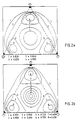
- FIG. 2 to 4 selected advantageous detection properties for a surface 3 (cell), which is designed as a triangular surface, are shown.
- the mushroom-shaped radar systems are located at the corner points of a triangle, which is also called the basic cell.
- FIG. 2a shows curves of constant positional accuracy in the area of the basic cells shown in broken lines for a moving or non-moving target.
- the specified so-called CEP values are standardized to the distance measurement accuracy of the at the corner points located radar systems. It can be seen that the position accuracy is advantageously almost independent of location. The differences resulting from curves 1 to 4 are negligible in practical use.
- FIG. 2b is the representation corresponding to FIG. 2a belonging ellipticity (axis ratio) of the error ellipses is shown. It can be seen that a possibly inaccurate position determination of a target is only present in the immediate vicinity (curves 8) of the radar systems.
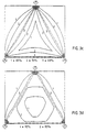
- the probability of resolution P res for a single radar system is shown. This is located on the left corner of the basic cell. The distance between the corner points is approximately 1 km.
- the (single) radar systems each have a range resolution of 2 m and an azimuth resolution of 2 °.
- FIG. 3c shows a representation corresponding to FIG. 3a, but with the difference that a radar system according to FIG. 3a is present.
- FIG. 4a, 4b show the achievable accuracy of determining a speed vector for a target within a basic cell in accordance with the representations of FIG. 3c, 3d.
- FIG. 4a shows curves of constant accuracy of the speed vector in the area of the basic cell.
- the CEP information used is standardized to the Doppler measurement accuracy of the individual radar systems located at the corner points. It can be seen that the velocity vector can be determined with an accuracy which is almost constant within the Magnolia cells.
- FIG. 4b shows the FIG. 4a belonging ellipticity of the error ellipses.
- the invention is not limited to the exemplary embodiments described, but can be applied to others in a variety of ways. For example, reliable monitoring of a national border in the case of difficult topography, e.g. B. in the mountains, possible. Furthermore, reliable monitoring of ports, rivers, bays and / or straits is possible.
Landscapes
- Engineering & Computer Science (AREA)
- Radar, Positioning & Navigation (AREA)
- Remote Sensing (AREA)
- Computer Networks & Wireless Communication (AREA)
- Physics & Mathematics (AREA)
- General Physics & Mathematics (AREA)
- Radar Systems Or Details Thereof (AREA)
- Medicines That Contain Protein Lipid Enzymes And Other Medicines (AREA)
Abstract
Description
Die Erfindung betrifft ein Verfahren zur Überwachung eines Gebietes nach dem Oberbegriff des Patentanspruchs 1. Ein solches Verfahren ist aus der GB-A-2 165 414 bekannt.The invention relates to a method for monitoring an area according to the preamble of
Die Erfindung betrifft insbesondere die Überwachng eines Gebietes, auf dem mindestens ein nichtkooperatives (Radar-)Ziel vorhanden ist. Ei solches Ziel besitzt keinen sogenannten Transponder una/oder keine Navigationsanlage, deren Navigationsergebnis durch eine ortsfeste (Radar-)Sende-/Empfangsanlage abfragbar ist.The invention particularly relates to the surveillance of an area in which at least one non-cooperative (radar) target is present. Such a destination has no so-called transponder and / or no navigation system, the navigation result of which can be queried by a fixed (radar) transmission / reception system.
Ein solches Gebiet kann z.B. ein sogenannter Regionalflugplatz sein, auf dem nach Sichtflugregeln abgefertigt wird. Das Gebiet kann z. B. auch ein zu einem Großflughafen gehörendes Vorfeld sein, auf dem z. B. neben den ruhenden oder bewegten Flugzeugen auch ruhende oder bewegte Fahrzeuge, z. B. Zubringerbusse und/oder Versorgungsfahrzeuge, überwacht werden müssen. Weiterhin kann das Gebiet z. B. auch ein Schiffahrtsweg, z. B. ein Fluß und/oder ein Kanal oder eine Hafenanlage sein.Such an area can be, for example, a so-called regional airfield, which is handled according to visual flight rules. The area can e.g. B. also be an apron belonging to a major airport, on the z. B. next to the resting or moving aircraft also stationary or moving vehicles, e.g. B. feeder buses and / or supply vehicles must be monitored. Furthermore, the area can e.g. B. also a shipping route, e.g. B. a river and / or a canal or a port facility.
Auf solchen Gebieten sind sehr unterschiedliche Arten von (Radar-)Zielen vorhanden, die möglichst genau geortet und klassifiziert werden müssen.There are very different types of (radar) targets in such areas, which must be located and classified as precisely as possible.
Es ist nun naheliegend, ein solches Gebiet mit Hilfe einer einzigen leistungsstarken Radaranlage zu überwachen. Ein solches Verfahren hat insbesondere bei einer ungünstigen Topographie des zu überwachenden Gebietes den Nachteil, daß sogenannte Abschattungen auftreten können, in denen keine zuverlässige Überwachung möglich ist.It is now obvious to monitor such an area with the help of a single powerful radar system. Such a method has the disadvantage, particularly in the case of an unfavorable topography of the area to be monitored, that so-called shadowing can occur in which reliable monitoring is not possible.
Der Erfindung liegt daher die Aufgabe zugrunde, ein gattungsgemäßes Verfahren anzugeben, das eine lückenlose, verzugsarme, genaue und möglichst zielortunabhängige Ortung, Klassifikation und Verfolgung von stationären und/oder bewegten Objekten (Zielen) in dem zu überwachenden Gebiet ermöglicht. Der Erfindung liegt außerdem die Aufgabe zugrunde, ein kostengünstig und zuverlässig arbeitendes Verfahren anzugeben.The invention is therefore based on the object of specifying a generic method which enables complete, low-warpage, accurate and, as far as possible, location-independent location, classification and tracking of stationary and / or moving objects (targets) in the area to be monitored. The invention is also based on the object of specifying an inexpensive and reliable method.
Diese Aufgabe wird gelöst durch die im kennzeichnenden Teil des Patentanspruchs 1 angegebenen Merkmale. Vorteilhafte Ausgestaltungen und/oder Weiterbildungen sind den Unteransprüchen entnehmbar.This object is achieved by the features specified in the characterizing part of
Ein erster Vorteil der Erfindung besteht darin, daß in einem zu überwachenden Gebiet eine gleichförmig genaue und leistungsgesteigerte Ortung und Klassifikation mit einem Verbund hochauflösender, kostengünstiger und räumlich kleiner Radarsensoren beschränkter Reichweite möglich wird.A first advantage of the invention consists in the fact that in an area to be monitored, a uniformly accurate and improved location and classification with a combination of high-resolution, inexpensive and spatially small radar sensors of limited range is possible.
Ein zweiter Vorteil besteht darin, daß eine an das zu überwachende Gebiet (Gelände) angepaßte Aufstellung der Radaranlagen und/oder Radarsensoren möglich wird und damit eine lückenlose und abschattungsfreie Überwachung.A second advantage consists in the fact that a positioning of the radar systems and / or radar sensors that is adapted to the area to be monitored is possible and thus a complete and shadow-free monitoring.
Ein dritter Vorteil besteht darin, daß für Radaranlagen (Radarsensoren) reichweitenbeschränkte Halbleitersender, die kostengünstig sind, verwendet werden können.A third advantage is that range-limited semiconductor transmitters, which are inexpensive, can be used for radar systems (radar sensors).
Ein vierter Vorteil besteht darin, daß das zu überwachende Gebiet in kleine Flächen, vorzugsweise aneinandergrenzende Dreiecke, aufgeteilt wird. Dadurch ist einerseits eine kostengünstige Erweiterung des zu überwachenden Gebietes möglich und andererseits noch eine genügende Überwachung, sofern eine der Radaranlagen (Radarsensoren) infolge eines Defektes oder Wartungsarbeiten ausfällt.A fourth advantage is that the area to be monitored is divided into small areas, preferably adjacent triangles. This enables, on the one hand, an inexpensive expansion of the area to be monitored and, on the other hand, sufficient monitoring if one of the radar systems (radar sensors) fails as a result of a defect or maintenance work.
Weitere Vorteile sind der folgenden Beschreibung entnehmbar.Further advantages can be found in the following description.
Die Erfindung wird im folgenden anhand von Ausführungsbeispielen unter Bezugnahme auf schematisch dargestellte Figuren näher erläutert. Die Figuren 1 bis 4 zeigen schemtisch dargestellte Diagramme zur Erläuterung der Erfindung.The invention is explained in more detail below on the basis of exemplary embodiments with reference to schematically illustrated figures. Figures 1 to 4 show schematically illustrated diagrams to explain the invention.
In FIG. 1 ist das zu überwachende Gebiet 1 in Form zweier parallel verlaufender Streifen, die mit einem grauen Punktraster unterlegt sind, dargestellt. Die parallelen Streifen sind außerdem durch einem schräg verlaufenden Streifen verbunden. Eine solche Darstellung kann z. B. einem Teilbereich eines Flughafens entsprechen, beispielsweise einem zu überwachenden Start- und/oder Landebahnenabschnitt oder Rollbahnen auf dem sogenannten Vorfeld. Die Darstellung kann aber auch einem zu überwachenden Kanal- oder Autostraßensystem entsprechen, das in einem topographisch unübersichtlichen Gelände liegt. Beispielsweise kann die Darstellung einem Kanal- oder Autostraßensystem entsprechen, zwischen dem ein hügeliges Gelände und/oder eine dichte Bebauung liegt.In FIG. 1 shows the
Ein solches zu überwachendes Gebiet wird nun in der dargestellten Weise mit einem Punktraster (große schwarze Punkte) überzogen. Diese Punkte 2 haben in Abhängigkeit von der vorhandenen Topographie einen Abstand, der in einem Bereich von vorzugsweise 0,3 km bis 3 km liegt. Die Punkte 2 sind aus Gründen des besseren Verständnisses mit Linien verbunden, so daß lückenlos aneinandergrenzende vieleckige Flächen 3 entstehen, die auch Zellen genannt werden. Diese Flächen 3 sind vorzugsweise als Dreiecke ausgebildet. Es sind aber auch andere Flächen (Zellen) möglich, z. B. Quadrate, Fünf- oder Sechsecke und/oder eine Mischung aus diesen. Die zu einer Fläche 3 (Zelle) gehörenden Punkte 3 (Eckpunkte) sind entsprechend den topographischen Gegebenheiten so gewählt, daß von jedem Punkt die zugehörige Fläche oder Flächen, z. B. sechs Stück für einen Punkt, der in der Mitte des Punktrasters liegt, nach optischen Sichtbedingungen (bei klarem Wetter) lückenlos und im wesentlichen abschattungsfrei überwacht werden kann. Die Punkte 2 können z. B. auf einem Hügel, einem Trägermast, einem Gebäude und/oder - bei ebenem Gelände - z. B. unmittelbar neben der zu überwachenden Start-/Landebahn oder dem Kanal- oder Autostraßensystem liegen.Such an area to be monitored is now covered with a dot matrix (large black dots) in the manner shown. Depending on the existing topography, these
An jedem der Punkte 2 wird nun eine Radaranlage, die auch Radarsensor genannt wird, angeordnet. Eine solche Radaranlage hat eine geringe Reichweite, die maximal bis zum nächstliegenden Punkt reicht, was nachfolgend noch näher erläutert wird. Solche Radaranlagen enthalten z. B. eine schnell rotierende, z. B. mit 60 Upm (Umdrehungen pro Minute), Sende-/Empfangsantenne, die als Reflektorantenne ausgebildet ist und einen maximalen Durchmesser von ungefähr 0,5 m besitzt. Eine solche Antenne wird vorteilhafterweise durch einen Radom geschützt. Für die Radaranlagen wird vorzugsweise ein CW-Bereich (Continous-Wave-Betrieb, Dauerstrich-Betrieb) mit einer daran angepaßten Modulation, gewählt. Die Radaranlagen arbeiten vorzugsweise im MMW-Bereich (Millimeterwellenbereich) und besitzen eine Sendeleistung, die vorzugsweise im Bereich von 50 mW bis 500 mW liegt. Solche Sendeanlagen sind kostengünstig in zuverlässiger Halbleiter-Technologie herstellbar.A radar system, which is also called a radar sensor, is now arranged at each of the
Diese Vielzahl der Radaranlagen wird gesteuert und/oder überwacht von einer Zentrale, die weit entfernt, z. B. einige Kilometer, von dem zu überwachenden Gebiet liegen kann. Durch eine solche Zentrale können in kostengünstiger Weise auch gleichzeitig mehrere solcher Gebiete überwacht werden. Die zwischen der Zentrale und den einzelnen Radaranlagen nötige (Daten-)Kommunikation erfolgt über dafür geeignete (Daten-)Übertragungsstrecken, z. B. elektrische Kabel, Lichtwellenleiter und/oder Funkstrecken, die vorzugsweise ebenfalls im Millimeterwellen-Bereich arbeiten. Von der Zentrale aus wird z. B. der Umlauf der Radarantennen und/oder die ausgestrahlten Millimeterwellen so synchronisiert, daß innerhalb einer Fläche 3 (Zelle) eine gemeinsame Signalverarbeitung der von der Radarantenne empfangenen Signale erfolgen kann. In der Zentrale befindet sich außerdem eine Auswerteeinheit, die vorzugsweise eine digital arbeitende Rechenanlage enthält, für die von den Radaranlagen empfangenen Signale. Diese können je nach dem erforderlichen Bedarf in vielfältiger Weise ausgewertet werden. Beispielsweise ist die Auswertung der Empfangssignale einer einzelnen Radaranlage und/oder der zu einer Fläche 3 (Zelle) gehörenden Radaranlagen und/oder der zu ausgewählten Flächen gehörenden Radaranlagen und/oder allen Radaranlagen möglich. Auf diese Weise sind z. B. (Radar-)Bilder mit unterschiedlicher räumlicher Auflösung darstellbar.This large number of radar systems is controlled and / or monitored by a control center that is far away, e.g. B. a few kilometers from the area to be monitored. Such a center can also be used to monitor several such areas at the same time in a cost-effective manner. The one between the head office and the individual radar systems Necessary (data) communication takes place via suitable (data) transmission links, e.g. B. electrical cables, optical fibers and / or radio links, which preferably also work in the millimeter wave range. From the head office is z. B. the rotation of the radar antennas and / or the emitted millimeter waves so synchronized that within a surface 3 (cell) a common signal processing of the signals received by the radar antenna can take place. In the center there is also an evaluation unit, which preferably contains a digitally operating computing system, for the signals received by the radar systems. These can be evaluated in a variety of ways, depending on the required requirements. For example, it is possible to evaluate the received signals from an individual radar system and / or the radar systems belonging to an area 3 (cell) and / or the radar systems belonging to selected areas and / or all radar systems. In this way, e.g. B. (Radar) images can be displayed with different spatial resolutions.
In den FIG. 2 bis 4 sind ausgewählte vorteilhafte Detektionseigenschaften für eine Fläche 3 (Zelle), die als dreieckige Fläche ausgebildet ist, dargestellt. Dabei befinden sich die pilzförmig dargestellten Radaranlagen an den Eckpunkten eines Dreiecks, das auch Basiszelle genannt wird.In the FIG. 2 to 4 selected advantageous detection properties for a surface 3 (cell), which is designed as a triangular surface, are shown. The mushroom-shaped radar systems are located at the corner points of a triangle, which is also called the basic cell.
FIG. 2a zeigt für ein bewegtes oder unbewegtes Ziel Kurven konstanter Positionsgenauigkeit im Bereich der gestrichelt dargestellten Basiszellen. Dabei sind die angegebenen sogenannten CEP-Werte (circular error probability) normiert auf die Entfernungsmeßgenauigkeit der an den Eckpunkten befindlichen Radaranlagen. Es ist ersichtlich, daß die Positionsgenauigkeit in vorteilhafter Weise nahezu ortsunabhängig ist. Die sich aus den Kurven 1 bis 4 ergebenden Unterschiede sind in der praktischen Anwendung vernachlässigbar.FIG. 2a shows curves of constant positional accuracy in the area of the basic cells shown in broken lines for a moving or non-moving target. The specified so-called CEP values (circular error probability) are standardized to the distance measurement accuracy of the at the corner points located radar systems. It can be seen that the position accuracy is advantageously almost independent of location. The differences resulting from
In FIG. 2b ist die zu der Darstellung entsprechend FIG. 2a gehörende Elliptizität (Achsenverhältnis) der Fehlerellipsen dargestellt. Es ist ersichtlich, daß lediglich in unmittelbarer Nähe (Kurven 8) der Radaranlagen eine möglicherweise ungenaue Positionsbestimmung eines Zieles vorhanden ist.In FIG. 2b is the representation corresponding to FIG. 2a belonging ellipticity (axis ratio) of the error ellipses is shown. It can be seen that a possibly inaccurate position determination of a target is only present in the immediate vicinity (curves 8) of the radar systems.
In den FIG. 3a, 3b ist die Auflösungswahrscheinlichkeit Pres für eine einzelne Radaranlage dargestellt. Diese befindet sich an dem linken Eckpunkt der Basiszelle. Bei dieser betragen die Abstände der Eckpunkte ungefähr 1 km. Die (Einzel-)Radaranlagen besitzen jeweils eine Entfernungsauflösung von 2 m und eine Azimutauflösung von 2°.In the FIG. 3a, 3b the probability of resolution P res for a single radar system is shown. This is located on the left corner of the basic cell. The distance between the corner points is approximately 1 km. The (single) radar systems each have a range resolution of 2 m and an azimuth resolution of 2 °.
FIG. 3a zeigt, daß ein Doppelziel, bei dem die zugehörigen Einzelziele einen Abstand d von nur 2,125 m besitzen, nahezu in der gesamten Basiszelle mit einer Auflösungswahrscheinlichkeit von Pres = 22 % detektiert werden kann. Lediglich in unmittelbarer Nähe der Radaranlage ist eine höhere Auflösungswahrscheinlichkeit vorhanden. FIG. 3b zeigt eine der FIG. 3a entsprechende Darstellung, jedoch mit dem Unterschied, daß die Einzelziele einen Abstand d = 2,5 m besitzen. Es ist ersichtlich, daß in der Basiszelle die Auflösungswahrscheinlichkeit auf Pres = 41 % gestiegen ist.FIG. 3a shows that a double target, in which the associated individual targets are at a distance d of only 2.125 m, can be detected in almost the entire basic cell with a resolution probability of P res = 22%. A higher resolution probability is only available in the immediate vicinity of the radar system. FIG. 3b shows one of the FIG. 3a corresponding representation, but with the difference that the individual targets have a distance d = 2.5 m. It can be seen that in the basic cell the probability of dissolution has increased to P res = 41%.
FIG. 3c zeigt eine Darstellung entsprechend FIG. 3a, jedoch mit dem Unterschied, daß an jedem Eckpunkt eine Radaranlage entsprechend FIG. 3a vorhanden ist. Bei dem aufzulösenden Doppelziel haben die Einzelziele einen Abstand von d = 2,125 m. Es ist ersichtlich, daß nun - im Gegensatz zu FIG. 3a - nahezu in der gesamten Basiszelle eine Auflösungswahrscheinlichkeit Pres > 50 % vorhanden ist, d. h., das Doppelziel wird aufgelöst in die vorhandenen Einzelziele.FIG. 3c shows a representation corresponding to FIG. 3a, but with the difference that a radar system according to FIG. 3a is present. In the double target to be resolved, the individual targets are at a distance of d = 2.125 m. It can be seen that - in contrast to FIG. 3a - there is a probability of dissolution P res > 50% in almost the entire basic cell, ie the double objective is resolved into the existing individual objectives.
Bei der Darstellung gemäß FIG. 3d besteht das Doppelziel aus zwei Einzelzielen mit einem Abstand d = 2,5 m. Es ist ersichtlich, daß ein solches Ziel - im Gegensatz zu FIG. 3b - nun zuverlässig auflösbar ist (Pres > 80 %).In the representation according to FIG. 3d, the double target consists of two single targets with a distance of d = 2.5 m. It can be seen that such a goal - in contrast to FIG. 3b - is now reliably resolvable (P res > 80%).
Die FIG. 4a, 4b zeigen die erreichbare Genauigkeit der Bestimmung eines Geschwindigkeitsvektors für ein Ziel innerhalb einer Basiszelle entsprechend den Darstellungen der FIG. 3c, 3d. FIG. 4a zeigt Kurven konstanter Genauigkeit des Geschwindigkeitsvektors im Bereich der Basiszelle. Dabei sind die verwendeten CEP-Angaben normiert auf die Dopplermeßgenauigkeit der an den Eckpunkten befindlichen Einzel-Radaranlagen. Es ist ersichtlich, daß der Geschwindigkeitsvektor mit einer Genauigkeit bestimmt werden kann, welche nahezu konstant ist innerhalb der Baiszellen.The FIG. 4a, 4b show the achievable accuracy of determining a speed vector for a target within a basic cell in accordance with the representations of FIG. 3c, 3d. FIG. 4a shows curves of constant accuracy of the speed vector in the area of the basic cell. The CEP information used is standardized to the Doppler measurement accuracy of the individual radar systems located at the corner points. It can be seen that the velocity vector can be determined with an accuracy which is almost constant within the mais cells.
FIG. 4b zeigt die zu FIG. 4a gehörende Elliptizität der Fehlerellipsen.FIG. 4b shows the FIG. 4a belonging ellipticity of the error ellipses.
Die anhand der FIG. 1 beschriebene Aufteilung des zu überwachenden Gebietes in vorzugsweise dreieckförmige Basiszellen, deren Eigenschaften anhand der FIG. 2 bis 4 dargestellt wurden, ermöglicht eine Radarüberwachung mit weiteren vorteilhaften Eigenschaften:
- Eine lückenlose sowie verzugarme, d. h. nahezu verzerrungsfreie Bestimmung der Position und/oder Geschwindigkeit aller in dem Gebiet befindlichen kooperativen und/oder nicht kooperativen (Radar-)Ziele.
- Eine zuverlässige Klassifikation aller Ziele, da diese immer aus mindestens drei unterschiedlichen Richtungen betrachtet werden. Auf diese Weise können beispielsweise Ziele unterschieden werden, die in einer bestimmten Richtung gleiche oder ähnliche Rückstreueigenschaften besitzen.
- Verwendung zirkular polarisierter Millimeterwellen mit polarimetrischer Auswertung orthogonaler Empfangskanäle. Dadurch ist insbesondere störender Clutter, der durch Niederschläge verursacht wird, in zuverlässiger Weise unterdrückbar.
- Es ist eine Radarkarte (Clutter Map) des überwachten Gebiets mit vorgebbarer zeitlicher Erneuerung darstellbar.
- Ermittlung und Auswertung der Zielattribute, z. B. geometrische Strukturmerkmale, Ausdehnung, Polarisationsmerkmale eines Zieles.
- Zentrale Spurbildung eines oder mehrerer bewegter Ziele auf der Basis der Position(en), Geschwindigkeitsvektoren sowie der Zielattribute.
- Zuverlässige Vorhersage eventueller Kollisionskonflikte zwischen mehreren Verkehrsteilnehmern (bewegter Zielen).
- Es ist eine einfache Erweiterung des zu überwachenden Gebietes möglich, z. B. bei einer Verlängerung einer Start- und/oder Landebahn eines Flughafens, ohne daß die erwähnten Genauigkeiten der Positions- und/oder Geschwindigkeitsbestimmungen verringert werden. Bei einer Erweiterung müssen einem bestehenden System von Basiszellen lediglich eine dem neuen zugeführten Gebiet entsprechende Anzahl neuer Basiszellen hinzugefügt werden.
- Es ist eine systeminhärende Redundanz beim Ausfall einzelner Radaranlagen vorhanden. Denn dann wird beispielsweise aus einer dreieckförmigen Basiszelle eine sechseckförmige Fläche, in der auch weiterhin eine Detektion von Zielen möglich ist, aber möglicherweise mit verringerter Detektionswahrscheinlichkeit. Eine solche Eigenschaft wird auch "Graceful Degradation" genannt.
- A complete and low distortion, ie almost distortion-free determination of the position and / or speed of all cooperative and / or non-cooperative (radar) targets located in the area.
- A reliable classification of all goals, since they are always viewed from at least three different directions. In this way, for example, a distinction can be made between targets which have the same or similar backscattering properties in a specific direction.
- Use of circularly polarized millimeter waves with polarimetric evaluation of orthogonal reception channels. As a result, disruptive clutter, which is caused by precipitation, can be suppressed in a reliable manner.
- A radar map (clutter map) of the monitored area can be displayed with predefinable temporal renewal.
- Determination and evaluation of the target attributes, e.g. B. geometric structural features, extent, polarization features of a target.
- Central tracking of one or more moving targets based on the position (s), speed vectors and the target attributes.
- Reliable prediction of possible collision conflicts between several road users (moving destinations).
- A simple expansion of the area to be monitored is possible, e.g. B. with an extension of a runway of an airport without the aforementioned accuracies of the position and / or speed determinations are reduced. In the case of an expansion, only a number of new basic cells corresponding to the new area supplied need to be added to an existing system of basic cells.
- There is inherent redundancy in the event of failure of individual radar systems. Because then, for example, a triangular base cell becomes a hexagonal area in which detection of targets is still possible, but possibly with a reduced detection probability. Such a property is also called "graceful degradation".
Die Erfindung ist nicht auf die beschriebenen Ausführungsbeispiele beschränkt, sondern in vielfältiger Weise auf weitere anwendbar. Beispielsweise ist eine zuverlässige Überwachung einer Landesgrenze bei schwieriger Topographie, z. B. im Gebirge, möglich. Weiterhin ist eine zuverlässige Überwachung von Häfen, Flußläufen, Meeresbuchten und/oder Meerengen möglich.The invention is not limited to the exemplary embodiments described, but can be applied to others in a variety of ways. For example, reliable monitoring of a national border in the case of difficult topography, e.g. B. in the mountains, possible. Furthermore, reliable monitoring of ports, rivers, bays and / or straits is possible.
Claims (8)
- Method of monitoring a region in which at least one non-co-operative target is present, with the aid of a radar installation, in which- a point grating is superimposed on the region to be monitored;- a radar installation which operates in CW mode is arranged at each point of the point grating;- the position of the points is selected in dependence on the topography of the region;characterised thereby- that at least three points are formed as corner points of an associated polygonal area (cell);- that at least the radar installations located at the corner points of the area are networked by way of an evaluating unit and a common signal processing for detection of the signals received by the radar antennae is carried out within an area; and- that the spacing of the points as well as the operating characteristics are selected in dependence on the detection characteristics required of the area.
- Method according to claim 1, characterised thereby that the position of the points is so selected at an area (cell) that an optical sighting connection exists therebetween and that the associated area (cell) can be monitored from each point free of shading.
- Method according to claim 1 or 2, characterised thereby- that at least two areas (cells) are arranged to adjoin gaplessly and possess a common boundary line;- that at least one point is formed as a corner point of two areas, and- that the at least two areas (cells) are monitored by the radar installations arranged at this corner point.
- Method according to one of the preceding claims, characterised thereby that the radar installations located at these points each have a coverage which reaches at most to the respectively adjacent point.
- Method according to one of the preceding claims, characterised thereby that the coverage of a radar installation lies in the region of 0.3 kilometres to 3 kilometres and that the selected coverage is chosen in dependence on the distance of the adjacent points.
- Method according to one of the preceding claims, characterised thereby- that radar installations with CW modulation are arranged at the corner points of at least one area (cell),- that the radar installations emit a circularly polarised radiation in the millimetre wave range, and- that a polarimetric evaluation of orthogonal receiving channels is carried out.
- Method according to one of the preceding claims, characterised thereby that at least at each area (cell) the signals received by radar installations located at the associated corner points are evaluated in a central evaluating unit.
- Method according to one of the preceding claims, characterised thereby that in the evaluating unit at least the position and vectorial velocity of the detected targets are determined and that the targets are classified.
Applications Claiming Priority (3)
| Application Number | Priority Date | Filing Date | Title |
|---|---|---|---|
| DE4216391 | 1992-05-18 | ||
| DE4216391 | 1992-05-18 | ||
| PCT/EP1993/000154 WO1993023768A1 (en) | 1992-05-18 | 1993-01-23 | Process for monitoring a zone |
Publications (2)
| Publication Number | Publication Date |
|---|---|
| EP0594797A1 EP0594797A1 (en) | 1994-05-04 |
| EP0594797B1 true EP0594797B1 (en) | 1996-11-13 |
Family
ID=6459153
Family Applications (1)
| Application Number | Title | Priority Date | Filing Date |
|---|---|---|---|
| EP93902244A Expired - Lifetime EP0594797B1 (en) | 1992-05-18 | 1993-01-23 | Process for monitoring a zone |
Country Status (5)
| Country | Link |
|---|---|
| US (1) | US5461384A (en) |
| EP (1) | EP0594797B1 (en) |
| CA (1) | CA2113454A1 (en) |
| DE (1) | DE59304473D1 (en) |
| WO (1) | WO1993023768A1 (en) |
Families Citing this family (10)
| Publication number | Priority date | Publication date | Assignee | Title |
|---|---|---|---|---|
| US5920318A (en) * | 1997-03-26 | 1999-07-06 | Northrop Grumman Corporation | Method and apparatus for localizing an object within a sector of a physical surface |
| DE102004062023B4 (en) * | 2004-12-23 | 2021-12-23 | Robert Bosch Gmbh | Radar system for monitoring targets in different distance ranges |
| EP1790994A1 (en) * | 2005-11-23 | 2007-05-30 | Ascom (Schweiz) AG | Method for triggering an event in response to a movement, system with a motion sensor and motion sensor |
| US20110221624A1 (en) * | 2007-12-05 | 2011-09-15 | Sensys Networks, Inc | Apparatus and Method Using a Radar in a Wireless and/or Wireline Sensor Node and Operating Radar In the Ground to Detect and Count Vehicles in Roadway, Parking Lot and Airport Applications |
| FR2942884B1 (en) | 2009-03-09 | 2011-04-01 | Onera (Off Nat Aerospatiale) | MULTISTATIC AIRPORT SURVEILLANCE RADAR SYSTEM |
| WO2013058830A1 (en) | 2011-10-19 | 2013-04-25 | Balu Subramanya | Directional speed and distance sensor |
| US8264401B1 (en) | 2011-12-29 | 2012-09-11 | Sensys Networks, Inc. | Micro-radar, micro-radar sensor nodes, networks and systems |
| US11004337B2 (en) | 2012-12-28 | 2021-05-11 | Balu Subramanya | Advanced parking management system |
| RU2596851C1 (en) * | 2015-07-22 | 2016-09-10 | Акционерное общество "НИИ измерительных приборов - Новосибирский завод имени Коминтерна" (АО "НПО НИИИП-НЗиК") | Method for radar scanning of space (versions) |
| WO2018226253A1 (en) * | 2016-12-16 | 2018-12-13 | The Government Of The United States Of America As Represented By The Secretary Of The Navy | Millimeter-wave terrain aided navigation system |
Family Cites Families (3)
| Publication number | Priority date | Publication date | Assignee | Title |
|---|---|---|---|---|
| GB2165414B (en) * | 1984-10-03 | 1988-01-13 | Standard Telephones Cables Plc | Runway occupancy warning system |
| GB2215932A (en) * | 1988-03-26 | 1989-09-27 | Gec Traffic Automation | Radio position finding system |
| NL9001599A (en) * | 1990-07-13 | 1992-02-03 | Frans Herman De Haan | DEVICE FOR LOCATING AND IDENTIFYING ANSWERS. |
-
1993
- 1993-01-23 CA CA002113454A patent/CA2113454A1/en not_active Abandoned
- 1993-01-23 DE DE59304473T patent/DE59304473D1/en not_active Expired - Fee Related
- 1993-01-23 WO PCT/EP1993/000154 patent/WO1993023768A1/en active IP Right Grant
- 1993-01-23 EP EP93902244A patent/EP0594797B1/en not_active Expired - Lifetime
-
1994
- 1994-01-05 US US08/175,345 patent/US5461384A/en not_active Expired - Fee Related
Also Published As
| Publication number | Publication date |
|---|---|
| WO1993023768A1 (en) | 1993-11-25 |
| CA2113454A1 (en) | 1993-11-25 |
| DE59304473D1 (en) | 1996-12-19 |
| EP0594797A1 (en) | 1994-05-04 |
| US5461384A (en) | 1995-10-24 |
Similar Documents
| Publication | Publication Date | Title |
|---|---|---|
| EP0016417B1 (en) | Airport surveillance system utilizing the secondary radar interrogation-response procedure | |
| US5663720A (en) | Method and system for regional traffic monitoring | |
| US5400031A (en) | Airport surface vehicle identification system and method | |
| EP0550073B1 (en) | System for locating multiple objects and obstacles and for detecting and determining the rolling state of moving objects, such as aircraft, ground vehicles, etc. | |
| DE102011010846B4 (en) | Method and system for visual connection-independent data transmission | |
| EP0594797B1 (en) | Process for monitoring a zone | |
| DE102008014330A1 (en) | Obstacle detection system, in particular for an anti-collision system | |
| DE2364086A1 (en) | SECONDARY RADAR PROCEDURE AND DEVICE FOR DETECTION OF A VEHICLE NEARBY | |
| EP3857256B1 (en) | Method for detecting road users | |
| WO2009156337A1 (en) | Method and apparatus for passive determination of target parameters | |
| EP0505827A1 (en) | Secondary radar system | |
| DE102013004463B4 (en) | Device and method for the detection of flying objects in the vicinity of wind turbines | |
| DE19910715C2 (en) | Process for autonomous driving robotic vehicles in halls and radar station for carrying out the process | |
| EP1595237A1 (en) | System for monitoring airport areas | |
| EP1153314B1 (en) | Method and device for determining a position | |
| WO2000043807A1 (en) | Arrangement for the interferometric radar measurement according to the rosar principle | |
| Nohara et al. | Affordable avian radar surveillance systems for natural resource management and BASH applications | |
| DE4315863A1 (en) | Monitoring region contg. non-cooperative target, e.g. regional airport | |
| EP0273326A2 (en) | Landing-aid system for aircraft having its own on-board radar | |
| WO2008040342A1 (en) | Radar system comprising only one sensor for detecting the surroundings of a motor vehicle | |
| DE2461945A1 (en) | GROUND LEVEL ANGLE REFLECTOR FOR NAVIGATION, REMOTE DISPLAY AND THEIR USE | |
| DE19522464A1 (en) | Radar system for monitoring of fixed area with uneven surface | |
| EP3737969A1 (en) | Traffic control method, radar sensor and radar sensor network | |
| EP0738900B1 (en) | Landing aid method for aircrafts | |
| DE977609C (en) | Method for the airspace surveillance of a larger area with the help of several impulse round search radar devices |
Legal Events
| Date | Code | Title | Description |
|---|---|---|---|
| PUAI | Public reference made under article 153(3) epc to a published international application that has entered the european phase |
Free format text: ORIGINAL CODE: 0009012 |
|
| 17P | Request for examination filed |
Effective date: 19931224 |
|
| AK | Designated contracting states |
Kind code of ref document: A1 Designated state(s): DE FR GB IT |
|
| RAP1 | Party data changed (applicant data changed or rights of an application transferred) |
Owner name: DAIMLER-BENZ AEROSPACE AKTIENGESELLSCHAFT |
|
| GRAG | Despatch of communication of intention to grant |
Free format text: ORIGINAL CODE: EPIDOS AGRA |
|
| 17Q | First examination report despatched |
Effective date: 19960305 |
|
| GRAH | Despatch of communication of intention to grant a patent |
Free format text: ORIGINAL CODE: EPIDOS IGRA |
|
| GRAH | Despatch of communication of intention to grant a patent |
Free format text: ORIGINAL CODE: EPIDOS IGRA |
|
| GRAA | (expected) grant |
Free format text: ORIGINAL CODE: 0009210 |
|
| ITF | It: translation for a ep patent filed |
Owner name: BARZANO' E ZANARDO MILANO S.P.A. |
|
| AK | Designated contracting states |
Kind code of ref document: B1 Designated state(s): DE FR GB IT |
|
| REF | Corresponds to: |
Ref document number: 59304473 Country of ref document: DE Date of ref document: 19961219 |
|
| ET | Fr: translation filed | ||
| GBT | Gb: translation of ep patent filed (gb section 77(6)(a)/1977) |
Effective date: 19970123 |
|
| PLBE | No opposition filed within time limit |
Free format text: ORIGINAL CODE: 0009261 |
|
| STAA | Information on the status of an ep patent application or granted ep patent |
Free format text: STATUS: NO OPPOSITION FILED WITHIN TIME LIMIT |
|
| 26N | No opposition filed | ||
| PGFP | Annual fee paid to national office [announced via postgrant information from national office to epo] |
Ref country code: GB Payment date: 20011214 Year of fee payment: 10 |
|
| PGFP | Annual fee paid to national office [announced via postgrant information from national office to epo] |
Ref country code: DE Payment date: 20011217 Year of fee payment: 10 |
|
| PGFP | Annual fee paid to national office [announced via postgrant information from national office to epo] |
Ref country code: FR Payment date: 20011226 Year of fee payment: 10 |
|
| REG | Reference to a national code |
Ref country code: GB Ref legal event code: IF02 |
|
| PG25 | Lapsed in a contracting state [announced via postgrant information from national office to epo] |
Ref country code: GB Free format text: LAPSE BECAUSE OF NON-PAYMENT OF DUE FEES Effective date: 20030123 |
|
| PG25 | Lapsed in a contracting state [announced via postgrant information from national office to epo] |
Ref country code: DE Free format text: LAPSE BECAUSE OF NON-PAYMENT OF DUE FEES Effective date: 20030801 |
|
| GBPC | Gb: european patent ceased through non-payment of renewal fee | ||
| PG25 | Lapsed in a contracting state [announced via postgrant information from national office to epo] |
Ref country code: FR Free format text: LAPSE BECAUSE OF NON-PAYMENT OF DUE FEES Effective date: 20030930 |
|
| REG | Reference to a national code |
Ref country code: FR Ref legal event code: ST |
|
| PG25 | Lapsed in a contracting state [announced via postgrant information from national office to epo] |
Ref country code: IT Free format text: LAPSE BECAUSE OF NON-PAYMENT OF DUE FEES;WARNING: LAPSES OF ITALIAN PATENTS WITH EFFECTIVE DATE BEFORE 2007 MAY HAVE OCCURRED AT ANY TIME BEFORE 2007. THE CORRECT EFFECTIVE DATE MAY BE DIFFERENT FROM THE ONE RECORDED. Effective date: 20050123 |