EP0591485B1 - Banknote reader - Google Patents
Banknote reader Download PDFInfo
- Publication number
- EP0591485B1 EP0591485B1 EP93907739A EP93907739A EP0591485B1 EP 0591485 B1 EP0591485 B1 EP 0591485B1 EP 93907739 A EP93907739 A EP 93907739A EP 93907739 A EP93907739 A EP 93907739A EP 0591485 B1 EP0591485 B1 EP 0591485B1
- Authority
- EP
- European Patent Office
- Prior art keywords
- banknote
- banknotes
- opening
- banknote reader
- reader according
- Prior art date
- Legal status (The legal status is an assumption and is not a legal conclusion. Google has not performed a legal analysis and makes no representation as to the accuracy of the status listed.)
- Expired - Lifetime
Links
- 238000012423 maintenance Methods 0.000 claims abstract description 16
- 238000009434 installation Methods 0.000 claims description 29
- 239000007788 liquid Substances 0.000 claims 1
- 238000012384 transportation and delivery Methods 0.000 abstract 1
- 238000012360 testing method Methods 0.000 description 10
- 238000013461 design Methods 0.000 description 3
- 230000003287 optical effect Effects 0.000 description 3
- 230000004888 barrier function Effects 0.000 description 2
- 210000001061 forehead Anatomy 0.000 description 2
- 238000004519 manufacturing process Methods 0.000 description 2
- 238000000034 method Methods 0.000 description 2
- 238000011160 research Methods 0.000 description 2
- 101001017827 Mus musculus Leucine-rich repeat flightless-interacting protein 1 Proteins 0.000 description 1
- 238000004140 cleaning Methods 0.000 description 1
- 238000010276 construction Methods 0.000 description 1
- 238000005520 cutting process Methods 0.000 description 1
- 230000001419 dependent effect Effects 0.000 description 1
- 238000001514 detection method Methods 0.000 description 1
- 239000000428 dust Substances 0.000 description 1
- 230000002349 favourable effect Effects 0.000 description 1
- 239000011152 fibreglass Substances 0.000 description 1
- 238000003780 insertion Methods 0.000 description 1
- 230000037431 insertion Effects 0.000 description 1
- 230000005285 magnetism related processes and functions Effects 0.000 description 1
- 238000005259 measurement Methods 0.000 description 1
- 230000005226 mechanical processes and functions Effects 0.000 description 1
- 230000009347 mechanical transmission Effects 0.000 description 1
- 239000002184 metal Substances 0.000 description 1
- 238000012544 monitoring process Methods 0.000 description 1
- 238000009420 retrofitting Methods 0.000 description 1
- 230000001960 triggered effect Effects 0.000 description 1
- XLYOFNOQVPJJNP-UHFFFAOYSA-N water Substances O XLYOFNOQVPJJNP-UHFFFAOYSA-N 0.000 description 1
Images
Classifications
-
- G—PHYSICS
- G07—CHECKING-DEVICES
- G07D—HANDLING OF COINS OR VALUABLE PAPERS, e.g. TESTING, SORTING BY DENOMINATIONS, COUNTING, DISPENSING, CHANGING OR DEPOSITING
- G07D7/00—Testing specially adapted to determine the identity or genuineness of valuable papers or for segregating those which are unacceptable, e.g. banknotes that are alien to a currency
- G07D7/06—Testing specially adapted to determine the identity or genuineness of valuable papers or for segregating those which are unacceptable, e.g. banknotes that are alien to a currency using wave or particle radiation
- G07D7/12—Visible light, infrared or ultraviolet radiation
- G07D7/128—Viewing devices
-
- G—PHYSICS
- G07—CHECKING-DEVICES
- G07D—HANDLING OF COINS OR VALUABLE PAPERS, e.g. TESTING, SORTING BY DENOMINATIONS, COUNTING, DISPENSING, CHANGING OR DEPOSITING
- G07D7/00—Testing specially adapted to determine the identity or genuineness of valuable papers or for segregating those which are unacceptable, e.g. banknotes that are alien to a currency
-
- G—PHYSICS
- G07—CHECKING-DEVICES
- G07D—HANDLING OF COINS OR VALUABLE PAPERS, e.g. TESTING, SORTING BY DENOMINATIONS, COUNTING, DISPENSING, CHANGING OR DEPOSITING
- G07D11/00—Devices accepting coins; Devices accepting, dispensing, sorting or counting valuable papers
- G07D11/10—Mechanical details
- G07D11/14—Inlet or outlet ports
-
- G—PHYSICS
- G07—CHECKING-DEVICES
- G07D—HANDLING OF COINS OR VALUABLE PAPERS, e.g. TESTING, SORTING BY DENOMINATIONS, COUNTING, DISPENSING, CHANGING OR DEPOSITING
- G07D11/00—Devices accepting coins; Devices accepting, dispensing, sorting or counting valuable papers
- G07D11/20—Controlling or monitoring the operation of devices; Data handling
- G07D11/22—Means for sensing or detection
-
- G—PHYSICS
- G07—CHECKING-DEVICES
- G07D—HANDLING OF COINS OR VALUABLE PAPERS, e.g. TESTING, SORTING BY DENOMINATIONS, COUNTING, DISPENSING, CHANGING OR DEPOSITING
- G07D11/00—Devices accepting coins; Devices accepting, dispensing, sorting or counting valuable papers
- G07D11/20—Controlling or monitoring the operation of devices; Data handling
- G07D11/26—Servicing, repairing or coping with irregularities, e.g. power failure or vandalism
-
- G—PHYSICS
- G07—CHECKING-DEVICES
- G07D—HANDLING OF COINS OR VALUABLE PAPERS, e.g. TESTING, SORTING BY DENOMINATIONS, COUNTING, DISPENSING, CHANGING OR DEPOSITING
- G07D11/00—Devices accepting coins; Devices accepting, dispensing, sorting or counting valuable papers
- G07D11/40—Device architecture, e.g. modular construction
-
- G—PHYSICS
- G07—CHECKING-DEVICES
- G07F—COIN-FREED OR LIKE APPARATUS
- G07F7/00—Mechanisms actuated by objects other than coins to free or to actuate vending, hiring, coin or paper currency dispensing or refunding apparatus
- G07F7/04—Mechanisms actuated by objects other than coins to free or to actuate vending, hiring, coin or paper currency dispensing or refunding apparatus by paper currency
Definitions
- the invention relates to a banknote reader in Preamble of claim 1 mentioned type.
- banknote readers are suitable, for example, for triggering a service at vending machines using predetermined Denominations of banknotes.
- U.S. Patents 4,807,736 and 4,885,744 describe compact ones Banknote readers for installation in vending machines that work together with a banknote container in the same frame to save space are accommodated.
- test device a buffer for the test device recognized and accepted banknotes. An order can only be triggered with such a banknote reader if the one required for the service, e.g. B. from several Banknotes composed amount already in the cache located.
- CH-PS 661 603 and the patents listed above show the arrangement of test equipment that the banknotes with a scan optical or magnetic methods, as well Facilities for the transportation of banknotes.
- the banknotes are in cash boxes known from CH-PS 658 736, for example stacked, secured against unauthorized theft of banknotes are.
- a stacking device shows the research disclosure, December 1984, RD 24820.
- a banknote reader using magnetic and optical sensors is disclosed in US 3,265,205.
- This Reader includes a transport and a test facility, that along a transport system inside the reader are arranged. If a banknote will be accepted , it becomes a cash box in the back transported by the reader. If the banknote is not to be adopted, it will become the front of the Readers returned where it can be removed.
- the invention is based, an inexpensive task To create banknote readers that do not have these disadvantages, but adapt easily to customer-specific needs leaves and is easy to maintain.
- the invention consists in the features specified in claim 1. Advantageous configurations result from the dependent ones Claims ..
- 1 means one of the two in a predetermined one Spacing arranged in parallel, essentially rectangular Side boards of a rectangular banknote reader, the Front part 2 easily replaceable on one narrow side of the Side boards 1 is attached.
- the side boards 1 are on the rear narrow side delimited by a border 3 or 3 '.
- the front part 2 has at least one acceptance opening 7 for banknotes 8.
- the border of the section 4 covers a base part 2 'of the front part 2, on which the front part 2 is attached to the side boards 1.
- the banknote reader is for protection against dust and mechanical Damage in a z. B. folded from sheet metal, tubular Inserted sleeve 9 of rectangular cross-section on a first narrow side 9 'between the side boards 1 arranged connection opening 10 releasably to the sleeve 9 connected money container 11 to the banknotes 8 after the Collect acceptance decision in the money container 11.
- the sleeve 9 is dimensioned in length so that the banknote reader of the Base section 2 'up to the edge 3 or 3' within the sleeve 9 is. Under the second narrow side 12, that of the first Opposite the narrow side 9, the side boards 1 have one Cutout for a flap 13.
- the flap 13 is anchored in the side boards 1 Axis pivotally mounted as a hinge 13 '. Once the Is pulled out of the sleeve 9, the flap 13th can be opened and allows free access for maintenance work on the Banknote reader in the interior 14 between the side boards 1. For example, in the drawing of Figure 1, the flap 13 Hinge 13 'in the immediate vicinity of the border 3 on, with the dashed lines the flap 13 at Indicate opening.
- the interior 14 of the banknote reader offers space for one System 15 for the transport of banknotes 8, which is a transport route sets on which the banknotes 8 individually by along the Blocks of the banknote reader arranged for transport be transported.
- the easily replaceable building blocks determine the function of the banknote reader and are fixed Allocated places along the transport route. For example, make up
- the transport system is guided by belts that are not shown here 15, with the axes of the rollers perpendicular to the side boards 1 pierce.
- a switch 19 can be located behind the test device 18 connect that into a return channel 20 through the End wall 2 and branches to a stacker 21.
- the stacker 21 installed in the interior 14, wherein the space for the non-installed blocks 19 and 21 for one any retrofitting remains free.
- the Acceptance opening 7 and the return channel 20 are in cross section narrow rectangles that are perpendicular to the side boards 1 are aligned and their width the dimensions of the largest Denomination corresponds to the banknotes 8 predetermined for acceptance. So that the banknote reader in many countries without major changes can be sold, the distance between the side boards 1 preferably according to the dimensions of the largest banknote, where the country-specific front part 2 according to the nominal values is selected.
- a space that is between the input channel 16 and the Stacker 21 leading to the front part 2 transport route is connected to the transport system 15 Drive unit 22 occupied.
- the transport path is folded. After the tester 18, the transport path bends 180 ° after the first narrow side 9 towards the front part 2 and leads between the tester 18 and the space for the stacker 21 through to the entrance of the switch 19, which is immediately behind the Return channel 20 is located.
- the transport route branches into the switch 19.
- One branch leads to the return channel 20, the other branch bends towards the stacker 21 again after the first Narrow side 9 by 180 ° in the direction of the rear edge 3. He opens into a conveyor belt 23 of the truck 21. All mechanical Functions of the stacker 21 are, for example, of the common drive unit 22 can be driven.
- the conveyor belt 23 extends parallel to the first narrow side 9 of the Turnout 19 to the rear edge 3, so that the transport route Z-folded.
- the stacker 21 points Disclosure, December 1984, RD 24820, a motor driven plunger, which from the conveyor belt 23 to the Connection opening 10 aligned banknotes 8 in the money container 11 promoted.
- the side boards 1 have a greater length, the extended part with the border 3 'in the drawing of the Figure 1 is drawn in dashed lines. It is also conceivable that the Intermediate cash register 24 can also be placed so that the Banknote readers have the advantage of being retrofittable with the Box office 24 has.
- the intermediate checkout 24 takes over from the customer individually through the Acceptance opening 7 entered banknotes 8 at the end of the conveyor belt 23 and places it on a by already entered one Banknotes shaped from bundle.
- the intermediate checkout 24 gives that Bundle on command from a control unit 25 back to the Conveyor belt 23, the bundle as a whole in the reverse direction from the conveyor belt 23 in the direction of Turnout 19 is transported.
- the bundle can from the stacker 21 in the Money container 11 pushed or from the conveyor belt 23 by means of a Guide plate 26 through the return channel 20 to the customer be returned.
- a control unit 25 monitors the functions of the banknote reader, evaluates the measurement results of the test device 18 and adds the service fulfills predetermined sales criteria of the vending machine 6 free.
- the control unit 25 is in the flap 13 installed, which is pivotable with this, so that both the control unit 25 and the Input channel 16 and the tester 18 from the second Narrow side 12 are easily accessible.
- the built-in blocks 16, 18, 19, 21, 22 and 24 are connected to the electronic control unit 25 connected to the necessary Manage data exchange or power supply.
- the Control unit 25 recognizes which of the modules 16, 18, 19, 21, 22 and 24 are connected to it, and is designed to be Program for reading banknotes according to the connected ones Modules 16, 18, 19, 21, 22 and 24 to adapt.
- the banknote reader has the advantage that additional functions are required later according to the additionally installed component executed or locked again without being removed Control unit 25 itself can be replaced or reprogrammed got to.
- the bank note 8 inserted through the acceptance opening 7 is in the Input channel 16 exactly aligned to the transport system 15, that detects the banknote 8 at the input 17 to the test device 18 and forwarded.
- the input channel 16 prevents it from being pushed further banknotes 8 until the checking device 18 for the next one Banknote 8 is free again.
- the checking device 18 scans characteristic features of the banknote 8 with an optical and / or magnetic process.
- the one Control device 25 transmitted measured values or derived therefrom Characteristic values are compared with stored target values. At of a match, the control unit 25 assesses the Banknote 8 as acceptable, the z. B. in the buffer 24th can be stored until the customer decides whether to use the Service desires or not. In the former case, the Buffer 24 stores banknotes 8 in stacker 21, which they with the motor-driven pestle in the money container promoted.
- Buffer 24 transfers the banknotes 8 already entered to the Conveyor belt 23 from which the banknotes 8 through the space of the Stacker 21 conveyed through and the guide plate 26 in the switch 19 returns to the customer through the return channel 20.
- the banknote reader is 180 ° around its longitudinal axis rotated in the cutout 4 arranged so that the money container 11 is located above the side boards 1 and advantageous new installation options are accessible.
- the stacker 21 is necessary to Banknotes 8 (FIG. 1) upward into the money container 11 Plug. Only adjustment of the banknote reader for one Installation in this position is the replacement of the front part 2 ( Figure 1) against a front part 27, the acceptance opening 7 and Return channel 20 for more convenient insertion of banknotes 8 are designed differently, whereby from the customer's point of view Acceptance opening 7 is arranged below the return channel 20. Also at the front part 27 are the acceptance opening 7 and the return channel 20 towards the customer too inclined slightly downwards.
- the front part 2 and the front part 27 can be made entirely glass fiber reinforced plastic. This technique allowed good ergonomic forms of the acceptance opening 7 and of the return channel 20 inexpensive to manufacture. In the field of Acceptance opening 7 can be plugged into the control unit 25 connected signal display 7 'arranged, for example the Prompts the user to insert further banknotes 8.
- the transport system 15 formed transport route shown as an example in a U-shape. After the test device 18 bends the transport path 180 ° directly to the Stacker 21 and passes the banknote 8 directly to the Conveyor belt 23.
- the shorter transport path has the advantage that the banknote 8 reaches the stacker 21 faster.
- an intermediate checkout 24 (FIG. 1) is present, this includes Transport system 15 according to the tester 18 at the stacker entrance arranged switch 19, one branch of the transport route to Trunk route of the switch leads to in this trunk route at a turn of 180 °.
- the main route of switch 19 forms the conveyor belt 23.
- the switch 19 has pivotably arranged baffle 26, which by means of a Spring 26 'is held in the rest position, the Trunk route of the switch 19 forth the banknotes 8 into a branch 23 ' of the conveyor belt 23 z. B. steerable to the checkout 24 ( Figure 1) because the branch to the transport route is covered.
- Passive control of the switch 19 has the advantage the simplicity and a relief of the power supply and the Control unit 25 ( Figure 1), since only by reversing the Drive unit 22 ( Figure 1), i. H. by changing the transport direction, the transport route in the switch 19 is determined.
- the banknote reader has the advantage that after the simple Replacing the front part 2 against the front part 27 of the Application area of the banknote reader is expanded and that both simple and comfortable versions with the same building blocks can be manufactured and the simple ones Executions at any time, even under difficult conditions in the field can be retrofitted.
- the blocks with the same functions can be different Executions, wherein they meet the requirement regarding Space requirements and the transport route of the banknotes 8 meet have to.
- the test device 18 is an example at this point mentioned that, depending on the design, optically and / or magnetically Features of banknote 8 scans.
- the money container 11 has a lever 28 which is on a Slider to open and close its inlet opening works.
- An advantageously arranged on the money container 11 mechanical sensor 29 is for sensing the relative position of the Cash container 11 to the sleeve 9 or to the connection opening 10 set up.
- the sensor 29 prevents the cash container from opening 11 as long as the sensor 29 is not predetermined in the Sleeve 9 is engaged. Conversely, the money container 11 cannot be removed from the sleeve 9 when the connection opening 10 is still open and the sensor 29 is engaged. This increases the Security against unauthorized manipulation by unauthorized persons.
- the simplest version of the banknote reader described above without switch 19, stacker 21 and cash register 24 has one Transport path according to Figure 2 and is only in the installed position usable according to FIG. 1.
- the control unit 25 Accepted banknotes 8 are from the transport system 15 to the connection opening 10 out and fall loosely into the money container 11, which is an open container, for example a simple sack that can be. Unapproved banknotes will be 8 returned by the transport system 15.
- the banknote 8 is reversed by the transport system 15 the direction of transport again through the acceptance opening 7 User returned as soon as the controller 25 for the Return has decided.
- the control unit 25 is advantageous for Detection of a coding in connection with the plug contact of the Signal display 7 'set up, for. B. by means of a short circuit bridge in the connector part.
- the control unit 25 reads the connector coding and is informed about the existence of the Return channel 20 so that the program of the control unit 25th adapts to the design of the banknote reader.
- banknote 8 To also secure the banknotes 8 with different widths To be able to recognize the banknotes 8 in the checking device 18 Align reading and recognizing. For this purpose, banknote 8 enter left-aligned into the acceptance opening 7 because this orientation is easiest for the customer. This requires however, an asymmetrical arrangement of the modules in the scaffolding the banknote reader and the inlet opening of the money container 11, to securely stack even narrow banknotes 8.
- the asymmetrical The arrangement requires a perpendicular to the side boards 1 Slidable arrangement of the building blocks to in all installation positions the banknote reader to the left-aligned input of banknotes 8 guarantee. Control over the predetermined location of the Banknote 8 can be in the acceptance opening 7 of the forehead or Front parts 2 and 27 take place.
- the locking of the sensor 29 is on one of the two permissible versions A and B of the Vote container 11.
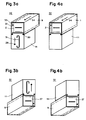
- FIGS. 3 and 4 show four possible combinations of Arrangement of the banknote reader and the money container 11 as they can be used for installation in the vending machine 6 ( Figure 1).
- the money container 11A is for the arrangement according to FIGS. 3a and 4b provided, while in Figures 3b and 4a the for Version A serves as a mirror image of the money container 11B is.
- the money container 11A is below the sleeve 9 arranged.
- the banknote reader is with the front part 2 equipped.
- the cash box 11A is replaceable cuboid cassette formed, the inlet opening on the Connection opening 10 ( Figure 1) aligned and when actuated the lever 28 can be closed by means of closing plates.
- Parallel to the longitudinal edges, the money container 11 has on both Side surfaces each have a groove 30, for example in the vicinity of Connection opening 10.
- the sleeve 9 is towards the money container 11 extended on both sides with profiles, so that when Insert the money container 11, the two grooves 30 in the Intervene profiles.
- the banknote reader and the money container 11 together form an installation unit 32.
- the money container 11 in The Swiss mentioned at the beginning shows a massive version Patent No. 658 736.
- the cash container 11 has a handle 31 on its front side and the lever 28.
- the handle 31 On the handle 31 is the money container 11, the with the grooves 30 slides in the profiles of the sleeve 9, convenient so far insertable until the sensor 29 ( Figure 2) in the predetermined position of the money container 11 engages and the Lever 28 for opening the inlet opening of the cash container 11 releases so that the installation unit 32 is ready for operation.
- the banknote reader is an advantage for easy maintenance within the sleeve 9 on at least one telescopic rail 33 arranged.
- the telescopic rails 33 are in this way on the side boards 1 ( Figure 1) attached that the flap 13 ( Figure 1) is concealed laterally, but outside the envelope 9 is freely pivotable.
- the banknote reader is therefore slightly out of the sleeve 9 with the front part 2 in the direction an arrow 34 can be pulled out for maintenance when the wall 5 ( Figure 1) of the vending machine 6 is removed.
- In its predetermined working position is by means of a second rotary lock lockable with key of the banknote reader.
- Below the telescopic rail 33 is still on the side board 1 a room 35 for further electronic circuits, mechanical Transmission means or a power supply for the banknote reader available.
- the installation unit 32 can be installed 3b may be required.
- the installation unit 32 is 180 ° about an axis perpendicular to the face 2 opposite the Arrangement rotated in Figure 3a and the front part 2 (Figure 3a) replaced with the ergonomically more favorable front part 27; this requires the use of the 11B cash container.
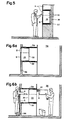
- FIG. 5 shows the vending machine 6 with the in the Operating position arranged installation unit 32, the for example in a building wall 36 in a niche 37 is installed.
- the niche 37 can be pulled out or the money container 11 interchangeable.
- the Money container 11B or 11A and the banknote reader opposed oriented to each other that is, the lever 28 ( Figure 3a) and the Front or front part 2 or 27 are on the two each other opposite sides of the installation unit 32 are arranged.
- the 11B and 11A version of the money container is from the wall 5 ( Figure 1) facing away from the installation unit 32 forth, and the banknote reader is opposite to the direction of arrow 34 extendable from the sleeve 9.
- the handle 31 (FIG. 3a) and the lever 28 (FIG. 3a) are not visible, as this on the front or front part 2 or 27 facing away from the installation unit 32 are arranged.
- FIG. 6a and 6b show the installation of the banknote reader in a security room 38 is shown, the one being the return / acceptance part trained end or front part 2 or 27 ( Figure 4b) and the wall 5 together with the building wall 36 the security room 38 demarcate from the audience.
- Both the money container 11 is interchangeable and the necessary maintenance can be carried out.
- the installation unit 32 is with Advantage arranged on roller bearings 39, 39 ', so that the installation unit 32 for maintenance without additional help from one Installer can be moved into the security room 38.
- the installation unit 32 can extend as far into the Security room 38 that the cash container 11 is pulled through the section 4 is no longer accessible through; this prevents an unauthorized person from cutting out 4 through to create money container 11. After completion the maintenance work is the installation unit 32 with little effort can be pushed back onto the wall 5 (FIG. 6a).
- the U-shaped transport path ( Figure 2) has another advantage easier accessibility.
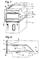
- the example is Installation unit in the arrangement according to FIG. 3a in FIG. 7 shown, the two side boards 1 of the scaffolding along a substantially diagonal dividing line 40 into one Upper part 41 and a lower part 42 are divided. The two parts of the scaffolding are together by means of a common Axis 43 at the level of the return channel 20 on the front or.
- Front part 2 or 27 ( Figure 2) opposite side articulated connected.
- the front or front part 2 or 27 is on the Lower part 42 arranged with a U-shaped Intermediate piece 44 for the connection to the money container 11 is equipped.
- the U-shaped intermediate piece 44 engages in the Grooves 30 of the cash box.
- the two side boards 1 of the Lower part 42 can advantageously each have three pins 45 in an identical manner
- Have arrangement with which the banknote reader in each Installation position is arranged on a mounting plate 46, wherein the space 35 between the side board 1 and the Mounting plate 46 remains free.
- Upper part 41 and the lower part 42 locked together.
- the Mounting plate 46 can be directly or through the Telescopic rail 33 ( Figure 6b) connected to the vending machine be.
- the hood 1 (FIG. 1) can also be omitted.
- the flap 13 with the control device 25 ( Figure 1) is advantageous with the hinge 13 'on the upper edge of one side board 1 of the upper part 41 articulated so that connector 47 for the signal and Supply lines can be led away to the rear and without interrupting this, the flap 13 around the hinge 13 ' remains easily pivotable. Unfolding the upper part 41 and / or pivoting of the flap 1 is therefore also in the Installation position possible.
- the Transport route in the area of the input channel 16 ( Figure 1) and the Tester 18 ( Figure 1) to be completely exposed, especially To maintain or adjust sensors of the test device 18.
- the banknotes 8 are shown schematically in FIG drawn, U-shaped transport path through the acceptance opening 7 entered in the front part 2, the banknote 8 in the direction of Arrows 48 is transported.
- the banknote reader is a instead of the stacker 21 ( Figure 2) the switch 19 ( Figure 1) controlled by the tester 18 ( Figure 1) Deflector 49 arranged.
- the deflector 49 can be in the transport route be pivoted in so that the banknote 8 ( Figure 1) deflected from the transport route into the money container 11 and falls into it. Is the acceptance of banknote 8 too refuse, the deflector 49 has pivoted out of the transport route, so that the banknote 8 is returned via the return channel 20 becomes.
Abstract
Description
Die Erfindung bezieht sich auf einen Banknotenleser der im
Oberbegriff des Anspruchs 1 genannten Art.The invention relates to a banknote reader in
Preamble of
Solche Banknotenleser eignen sich beispielsweise zum Auslösen einer Dienstleistung bei Verkaufsautomaten mittels vorbestimmten Nennwerten von Banknoten.Such banknote readers are suitable, for example, for triggering a service at vending machines using predetermined Denominations of banknotes.
Es ist ein Banknotenleser dieser Art aus der FR-A 2'453'811 bekannt, bei dem eine Eingangssperre vor einem Banknoten-Prüfgerät ein zu rasches Nachschieben weiterer Banknoten verhindert, bis das Prüfgerät die Echtheit der Banknote überprüft bzw, die Banknote zurückgewiesen oder gestapelt hat.It is a banknote reader of this type from FR-A 2'453'811 known, in which an input barrier in front of a banknote tester too fast feeding of further banknotes prevents the tester from checking the authenticity of the banknote or has rejected or stacked the banknote.
Die US-PS 4'807'736 und US-PS 4'858'744 beschreiben kompakte Banknotenlesegeräte zum Einbau in Verkaufgeräte, die zusammen mit einem Banknotenbehälter im gleichen Rahmen platzsparend untergebracht sind.U.S. Patents 4,807,736 and 4,885,744 describe compact ones Banknote readers for installation in vending machines that work together with a banknote container in the same frame to save space are accommodated.
Es ist auch bekannt (DE-OS 20 28 649 und DE-PS 26 19 620) nach dem Prüfgerät einen Zwischenspeicher für die vom Prüfgerät erkannten und akzeptierten Banknoten einzurichten. Ein Auftrag kann bei einem solchen Banknotenleser erst ausgelöst werden, wenn sich der für die Dienstleistung benötigte, z. B. aus mehreren Banknoten zusammengesetzte Betrag bereits im Zwischenspeicher befindet.It is also known (DE-OS 20 28 649 and DE-PS 26 19 620) the test device, a buffer for the test device recognized and accepted banknotes. An order can only be triggered with such a banknote reader if the one required for the service, e.g. B. from several Banknotes composed amount already in the cache located.
Die CH-PS 661 603 und die oben aufgeführten Patentschriften zeigen die Anordnung von Prüfgeräten, die die Banknoten mit einem optischen oder magnetischen Verfahren abtasten, sowie Einrichtungen zum Transport der Banknoten. Die Banknoten werden in bespielsweise aus der CH-PS 658 736 bekannten Geldkassetten gestapelt, die gegen unbefugtes Entwenden von Banknoten gesichert sind. Eine Stapelvorrichtung zeigt die Research Disclosure, December 1984, RD 24820. CH-PS 661 603 and the patents listed above show the arrangement of test equipment that the banknotes with a scan optical or magnetic methods, as well Facilities for the transportation of banknotes. The banknotes are in cash boxes known from CH-PS 658 736, for example stacked, secured against unauthorized theft of banknotes are. A stacking device shows the research disclosure, December 1984, RD 24820.
Ein Banknotenleser unter Verwendung magnetischer und optischer Sensoren ist in US 3 265 205 offenbart. Dieser Leser umfaßt eine Transport- und eine Prüfeinrichtung, die entlang eines Transportsystems im Inneren des Lesers angeordnet sind. Wenn eine Banknote angenommen werden soll, wird sie zu einer Geldkassette im hinteren Bereich des Lesers transportiert. Wenn die Banknote jedoch nicht angenommen werden soll, wird sie zur Vorderseite des Lesers zurückgegeben, wo sie entnommen werden kann.A banknote reader using magnetic and optical sensors is disclosed in US 3,265,205. This Reader includes a transport and a test facility, that along a transport system inside the reader are arranged. If a banknote will be accepted , it becomes a cash box in the back transported by the reader. If the banknote is not to be adopted, it will become the front of the Readers returned where it can be removed.
Die in diesen Patentschriften beschriebenen Einrichtungen weisen den Nachteil auf, dass jede der beschriebenen Ausführungen für die Bedürfnisse eines bestimmten Kundenkreises zugeschnitten ist, relativ viel Platz beansprucht und keine einfachen Aenderungen der Konstruktion zulässt.Those described in these patents Show facilities the disadvantage that each of the designs described for is tailored to the needs of a specific group of customers, takes up a lot of space and no simple changes the construction allows.
Der Erfindung liegt die Aufgabe zugrunde, einen kostengünstigen Banknotenleser zu schaffen, der diese Nachteile nicht aufweist, sondern sich leicht an kundenspezifische Bedürfnisse anpassen lässt und wartungsfreundlich ist.The invention is based, an inexpensive task To create banknote readers that do not have these disadvantages, but adapt easily to customer-specific needs leaves and is easy to maintain.
Die Erfindung besteht in den im Anspruch 1 angegebenen Merkmalen.
Vorteilhafte Ausgestaltungen ergeben sich aus den abhängigen
Ansprüchen..The invention consists in the features specified in
Nachfolgend werden Ausführungsbeispiele der Erfindung anhand der Zeichnungen näher erläutert.Exemplary embodiments of the invention are described below with reference to Drawings explained in more detail.
Es zeigt:
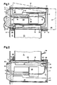
Figur 1- einen quaderförmigen Banknotenleser mit einem darunter angeordneten Geldbehälter,
Figur 2- einen Banknotenleser mit oberhalb des Gehäuses angeordnetem Geldbehälter,
- Figur 3 a und b
- eine Einbaueinheit für Wartungsarbeiten von vorne,
- Figur 4 a und b
- die Einbaueinheit für rückwärtige Wartungsarbeiten,
Figur 5- einen Verkaufsautomaten,
- Figur 6 a und b
- einen Verkaufsautomaten mit einem Sicherheitsraum für die Wartung,
Figur 7- die Einbaueinheit mit einer Befestigungsplatte und
- Figur 8
- einen Banknotenleser mit einem Ablenker.
- Figure 1
- a cuboid banknote reader with a money container arranged underneath,
- Figure 2
- a banknote reader with a money container arranged above the housing,
- Figure 3 a and b
- an installation unit for maintenance work from the front,
- Figure 4 a and b
- the installation unit for rear maintenance work,
- Figure 5
- a vending machine,
- Figure 6 a and b
- a vending machine with a security room for maintenance,
- Figure 7
- the installation unit with a mounting plate and
- Figure 8
- a banknote reader with a deflector.
In der Figur 1 bedeutet 1 eine der beiden in einem vorbestimmten
Abstand parallel angeordneten, im wesentlichen rechteckigen
Seitenplatinen eines quaderförmigen Banknotenlesers, dessen
Stirnteil 2 leicht austauschbar an der einen Schmalseite der
Seitenplatinen 1 befestigt ist. Die Seitenplatinen 1 sind an der
hinteren Schmalseite durch eine Berandung 3 bzw. 3' begrenzt. In
der Arbeitsstellung des Banknotenlesers ragt das Stirnteil 2
durch einen Ausschnitt 4 in einer Wand 5 hindurch, z. B. aus
einem Verkaufsautomaten 6 heraus. Das Stirnteil 2 besitzt
wenigstens eine Annahmeöffnung 7 für Banknoten 8. Die Berandung
des Ausschnitts 4 verdeckt eine Sockelpartie 2' des Stirnteils 2,
auf der das Stirnteil 2 an den Seitenplatinen 1 befestigt ist.
Die gemeinsamen Berührungsflächen der Berandung des Ausschnitts 4
mit der Sockelpartie 2' sind so gewählt, dass sie einen Zugang
zum Innern des Verkaufsautomaten 6 verhindern.In FIG. 1, 1 means one of the two in a predetermined one
Spacing arranged in parallel, essentially rectangular
Side boards of a rectangular banknote reader, the
Der Banknotenleser ist zum Schutz vor Staub und mechanischen
Beschädigungen in eine z. B. aus Blech gefaltetete, rohrförmige
Hülse 9 von rechteckigem Querschnitt eingeschoben, die auf einer
ersten Schmalseite 9' eine zwischen den Seitenplatinen 1
angeordnete Verbindungsöffnung 10 zu einem mit der Hülse 9 lösbar
verbundenen Geldbehälter 11 aufweist, um die Banknoten 8 nach der
Annahmeentscheidung im Geldbehälter 11 zu sammeln. Die Hülse 9
ist in ihrer Länge so bemessen, dass der Banknotenleser von der
Sockelpartie 2' bis zur Berandung 3 bzw. 3' innerhalb der Hülse 9
ist. Unter der zweiten Schmalseite 12, die der ersten
Schmalseite 9 gegenüberliegt, weisen die Seitenplatinen 1 einen
Ausschnitt für eine Klappe 13 auf.The banknote reader is for protection against dust and mechanical
Damage in a z. B. folded from sheet metal, tubular
Die Klappe 13 ist um eine in den Seitenplatinen 1 verankerte
Achse als Scharnier 13' verschwenkbar gelagert. Sobald der
Banknotenleser aus der Hülse 9 gezogen ist, ist die Klappe 13
aufklappbar und ermöglicht freien Zugang für Wartungsarbeiten am
Banknotenleser im Innenraum 14 zwischen den Seitenplatinen 1.
Beispielhaft weist in der Zeichnung der Figur 1 die Klappe 13 das
Scharnier 13' in der unmittelbaren Nachbarschaft zur Berandung 3
auf, wobei die gestrichelt gezeichneten Linien die Klappe 13 beim
Oeffnen andeuten.The
Der Innenraum 14 des Banknotenlesers bietet Platz für ein
System 15 zur Beförderung der Banknoten 8, das einen Transportweg
festlegt, auf dem die Banknoten 8 einzeln durch längs des
Transportwegs angeordnete Bausteine des Banknotenlesers hindurch
transportiert werden. Die leicht auswechselbaren Bausteine
bestimmen die Funktion des Banknotenlesers und sind festen
Plätzen längs des Transportwegs zugeordnet. Beispielsweise bilden
über Rollen geführte, hier nicht gezeigte Bänder das Transportsystem
15, wobei die Achsen der Rollen senkrecht die Seitenplatinen
1 durchstossen.The interior 14 of the banknote reader offers space for one
Unmittelbar hinter der Annahmeöffnung 7 schliesst sich ein
Eingangskanal 16 an, der sich bis zu einem Eingang 17 eines
Prüfgeräts 18 zum Erkennen der Echtheit der Banknoten 8
erstreckt. Hinter dem Prüfgerät 18 kann sicn eine Weiche 19
anschliessen, die sich in einen Rückgabekanal 20 durch die
Stirnwand 2 hindurch und zu einem Stapler 21 verzweigt. In der
einfachsten Ausführung des Banknotenlesers sind weder die
Weiche 19 noch der Stapler 21 im Innenraum 14 eingebaut, wobei
der Platz für die nicht eingebauten Bausteine 19 und 21 für eine
allfällige Nachrüstung freibleibt. Die Seitenplatinen 1 bilden
daher ein Einbaugerüst des Banknotenlesers.Immediately behind the
Sowohl die Annahmeöffnung 7 als auch der Rückgabekanal 20 - falls
vorhanden - durchdringen das Stirnteil 2 vom Innenraum 14 zum
Benutzer mit einer leichten Neigung nach unten, damit allfälliges
Spritzwasser nicht in den Innenraum 14 eindringen kann. Die
Annahmeöffnung 7 und der Rückgabekanal 20 sind im Querschnitt
schmale Rechtecke, die senkrecht zu den Seitenplatinen 1
ausgerichtet sind und deren Breite den Abmessungen des grössten
Nennwertes der zur Annahme vorbestimmten Banknoten 8 entspricht.
Damit der Banknotenleser in vielen Ländern ohne grosse Aenderung
verkaufbar ist, richtet sich der Abstand der Seitenplatinen 1
vorzugsweise nach den Abmessungen der grössten Banknote, wobei
das länderspezifische Stirnteil 2 entsprechend den Nennwerten
ausgewählt wird. Both the
Ein Raum, der sich zwischen dem Eingangskanal 16 und dem über den
Stapler 21 hinweg zum Stirnteil 2 führenden Transportweg
befindet, ist mit einer mit dem Transportsystem 15 gekoppelten
Antriebseinheit 22 belegt.A space that is between the
Um die Länge des Banknotenlesers zu beschränken und den
Innenraum 14 optimal auszunutzen, ist der Transportweg gefaltet.
Nach dem Prüfgerät 18 biegt der Transportweg um 180° nach der
ersten Schmalseite 9 hin gegen den Stirnteil 2 ab und führt
zwischen dem Prüfgerät 18 und dem Raum für den Stapler 21
hindurch zum Eingang der Weiche 19, die unmittelbar hinter dem
Rückgabekanal 20 gelegen ist.To limit the length of the banknote reader and the
To make optimum use of interior space 14, the transport path is folded.
After the
Ist die Weiche 19 eingebaut, verzweigt sich der Transportweg in
der Weiche 19. Der eine Zweig führt zum Rückgabekanal 20, der
andere Zweig biegt zum Stapler 21 hin wieder nach der ersten
Schmalseite 9 um 180° in Richtung zur hinteren Berandung 3 ab. Er
mündet in ein Transportband 23 des Staplers 21. Alle mechanischen
Funktionen des Staplers 21 sind beispielsweise von der
gemeinsamen Antriebseinheit 22 antreibbar. Das Transportband 23
erstreckt sich parallel zur ersten Schmalseite 9 von der
Weiche 19 bis zur hinteren Berandung 3, so dass der Transportweg
Z-artig gefaltet ist.If the
Der Stapler 21 weist gemäss der eingangs erwähnten Research
Disclosure, December 1984, RD 24820, einen motorisch
angetriebenen Stössel auf, der die vom Transportband 23 auf die
Verbindungsöffnung 10 ausgerichteten Banknoten 8 in den Geldbehälter
11 befördert.According to the research mentioned at the outset, the
Falls eine Zwischenkasse 24 für Banknoten 8 vorgesehen ist,
weisen die Seitenplatinen 1 eine grössere Länge auf, wobei die
verlängerte Partie mit der Berandung 3' in der Zeichnung der
Figur 1 gestrichelt gezeichnet ist. Es ist auch denkbar, dass die
Zwischenkasse 24 zusätzlich aufgesetzt werden kann, so dass der
Banknotenleser den Vorteil der Nachrüstbarkeit mit der
Zwischenkasse 24 hat. If an
Die Zwischenkasse 24 übernimmt die vom Kunden einzeln durch die
Annahmeöffnung 7 eingegebenen Banknoten 8 am Ende des Transportbandes
23 und legt sie auf ein durch bereits eingegebene
Banknoten geformtes Bündel ab. Die Zwischenkasse 24 gibt das
Bündel auf einen Befehl eines Steuergeräts 25 wieder an das
Transportband 23 ab, wobei das Bündel als ganzes in der
umgegekehrten Richtung vom Transportband 23 in der Richtung zur
Weiche 19 befördert wird. Das Bündel kann vom Stapler 21 in den
Geldbehälter 11 gestossen oder vom Transportband 23 mittels eines
Leitblechs 26 durch den Rückgabekanal 20 hindurch dem Kunden
zurückgegeben werden.The
Ein Steuergerät 25 überwacht die Funktionen des Banknotenlesers,
wertet die Messergebnisse des Prüfgeräts 18 aus und gibt bei
einer Erfüllung vorbestimmter Verkaufskriterien die Dienstleistung
des Verkaufsautomaten 6 frei. Das Steuergerät 25 ist in
der Klappe 13 eingebaut, der mit dieser verschwenkbar ist, so
dass bei Wartungsarbeiten sowohl das Steuergerät 25 als auch der
Eingangskanal 16 und das Prüfgerät 18 von der zweiten
Schmalseite 12 leicht zugänglich sind. Die eingebauten Bausteine
16, 18, 19, 21, 22 und 24 sind über Leitungen mit dem
elektronischen Steuergerät 25 verbunden, die den notwendigen
Datenaustausch oder die Energieversorgung bewerkstelligen. Das
Steuergerät 25 erkennt, welche der Bausteine 16, 18, 19, 21, 22
und 24 mit ihm verbunden sind, und ist dazu eingerichtet, sein
Programm zum Banknotenlesen entsprechend den angeschlossenen
Bausteinen 16, 18, 19, 21, 22 und 24 anzupassen. Der Banknotenleser
weist den Vorteil auf, dass nachträglich gewünschte Zusatzfunktionen
entsprechend des zusätzlich eingebauten Bauteils
ausgeführt oder wieder ausgebaute gesperrt werden, ohne dass das
Steuergerät 25 selbst ausgewechselt oder umprogrammiert werden
muss.A
Hier nicht gezeigt sind die für die Ueberwachung der Beförderung
der Banknoten 8 notwendigen Sensoren, wie z. B. Lichtschranken,
und ihre Verbindungen zum Steuergerät 25. Not shown here are those for monitoring the transport
the banknotes 8 necessary sensors, such as. B. light barriers,
and their connections to the
Die durch die Annahmeöffnung 7 eingeschobene Banknote 8 wird im
Eingangskanal 16 genau auf das Transportsystem 15 ausgerichtet,
das die Banknote 8 am Eingang 17 zum Prüfgerät 18 erfasst und
weiterbefördert. Der Eingangskanal 16 verhindert ein Nachschieben
weiterer Banknoten 8, bis das Prüfgerät 18 für die nächste
Banknote 8 wieder frei ist.The bank note 8 inserted through the
Das Prüfgerät 18 tastet kennzeichnende Merkmale der Banknote 8
mit einem optischen und/oder magnetischen Verfahren ab. Die dem
Steuergerät 25 übermittelten Messwerte oder daraus abgeleitete
Kennwerte werden mit gespeicherten Sollwerten verglichen. Bei
einer Uebereinstimmung beurteilt das Steuergerät 25 die
Banknote 8 als akzeptierbar, die z. B. im Zwischenspeicher 24
eingelagert werden kann, bis der Kunde entscheidet, ob er die
Dienstleistung wünscht oder nicht. Im ersteren Fall befördert der
Zwischenspeicher 24 die Banknoten 8 in den Stapler 21, der sie
mit dem motorisch angetriebenen Stössel in den Geldbehälter
befördert. Bricht der Benutzer die Noteneingabe ab, gibt der
Zwischenspeicher 24 die bereits eingegebenen Banknoten 8 an das
Transportband 23 ab, das die Banknoten 8 durch den Raum des
Staplers 21 hindurch befördert und sie über das Leitblech 26 in
der Weiche 19 dem Kunden durch den Rückgabekanal 20 zurückgibt.The checking
In der Figur 2 ist der Banknotenleser um 180° um seine Längsachse
gedreht im Ausschnitt 4 angeordnet, so dass sich der Geldbehälter
11 oberhalb der Seitenplatinen 1 befindet und
vorteilhaft neue Einbaumöglichkeiten erschliessbar sind. In
dieser Ausführung ist der Stapler 21 notwendig, um die
Banknoten 8 (Figur 1) nach oben in den Geldbehälter 11 zu
stopfen. Einzige Anpassung des Banknotenlesers für einen
Einbau in dieser Lage ist der Austausch des Stirnteils 2
(Figur 1) gegen ein Frontteil 27, dessen Annahmeöffnung 7 und
Rückgabekanal 20 zum bequemeren Einführen der Banknoten 8
verschieden gestaltet sind, wobei vom Kunden her gesehen die
Annahmeöffnung 7 unterhalb des Rückgabekanals 20 angeordnet ist.
Auch beim Fronteil 27 sind die Annahmeöffnung 7 und der Rückgabekanal
20 gegen den Kunden zu ebenfalls leicht nach unten geneigt. In Figure 2, the banknote reader is 180 ° around its longitudinal axis
rotated in the
Das Stirnteil 2 und das Frontteil 27 können ganz aus
glasfaserverstärktem Kunststoff geformt sein. Diese Technik
gestattet, gute ergonometrische Formen der Annahmeöffnung 7 und
des Rückgabekanals 20 kostengünstig herzustellen. Im Bereich der
Annahmeöffnung 7 ist eine mit dem Steuergerät 25 steckbar
verbundene Signalanzeige 7' angeordnet, die beispielsweise den
Benutzer zum Einführen weiterer Banknoten 8 auffordert.The
In der Zeichnung der Figur 2 ist der vom Transportsystem 15
gebildete Transportweg beispielhaft U-förmig dargestellt. Nach
dem Prüfgerät 18 biegt der Transportweg um 180° direkt zum
Stapler 21 ab und übergibt die Banknote 8 direkt an das
Transportband 23. Der kürzere Transportweg weist den Vorteil auf,
dass die Banknote 8 schneller den Stapler 21 erreicht.2 is that of the
Falls eine Zwischenkasse 24 (Figur 1) vorhanden ist, umfasst das
Transportsystem 15 die nach dem Prüfgerät 18 am Staplereingang
angeordnete Weiche 19, deren einen Zweig den Transportweg zur
Stammstrecke der Weiche leitet, um in diese Stammstrecke nach
einer Wende von 180° einzumünden. Die Stammstrecke der Weiche 19
bildet das Transportband 23. Die Weiche 19 weist ein
verschwenkbar angeordetes Leitblech 26 auf, das mittels einer
Feder 26' in der Ruhestellung gehalten wird, wobei von der
Stammstrecke der Weiche 19 her die Banknoten 8 in einen Zweig 23'
des Transportbands 23 z. B. zur Zwischenkasse 24 (Figur 1) lenkbar
sind, da der Zweig zum Transportweg abgedeckt ist. Eine vom
Transportweg zugeführte Banknote 8 verschwenkt das Leitblech 26
gegen die Kraft der Feder 26' vor den Zweig 23' und wird vom
Leitblech 26 zum Transportband 23 abgelenkt und in den Stapler 21
befördert. Die passive Steuerung der Weiche 19 weist den Vorteil
der Einfachheit und einer Entlastung der Stromversorgung und des
Steuergeräts 25 (Figur 1) auf, da nur durch Umsteuern der
Antriebseinheit 22 (Figur 1), d. h. durch Aendern der Transportrichtung,
der Transportweg in der Weiche 19 bestimmt wird.If an intermediate checkout 24 (FIG. 1) is present, this includes
Der Banknotenleser weist den Vorteil auf, dass nach dem einfachen
Auswechseln des Stirnteils 2 gegen den Frontteil 27 der
Anwendungsbereich des Banknotenlesers erweitert wird und dass
sowohl einfache als auch komfortable Ausführungen mit den
gleichen Bausteinen herstellbar sind und die einfachen
Ausführungen auch unter erschwerten Bedingungen im Feld jederzeit
nachgerüstet werden können.The banknote reader has the advantage that after the simple
Replacing the
Die Bausteine mit den gleichen Funktionen können verschiedene
Ausführungen aufweisen, wobei sie die Anforderung bezüglich des
Raumbedarfs und an den Transportweg der Banknoten 8 erfüllen
müssen. Beispielhaft ist an dieser Stelle das Prüfgerät 18
erwähnt, das je nach Ausführung optisch und/oder magnetisch die
Merkmale der Banknote 8 abtastet.The blocks with the same functions can be different
Executions, wherein they meet the requirement regarding
Space requirements and the transport route of the banknotes 8 meet
have to. The
Der Geldbehälter 11 besitzt einen Hebel 28, der auf einen
Schieber zum Oeffnen und Verschliessen seiner Einlassöffnung
wirkt. Ein mit Vorteil am Geldbehälter 11 angeordneter
mechanischer Fühler 29 ist zum Abtasten der relativen Lage des
Geldbehälters 11 zur Hülse 9 bzw. zur Verbindungsöffnung 10
eingerichtet. Der Fühler 29 verhindert ein Oeffnen des Geldbehälters
11, solange der Fühler 29 nicht vorbestimmt in die
Hülse 9 eingerastet ist. Umgekehrt kann der Geldbehälter 11 nicht
von der Hülse 9 entfernt werden, wenn die Verbindungsöffnung 10
noch offen ist und der Fühler 29 eingerastet ist. Dies erhöht die
Sicherheit gegen unerlaubte Manipulationen durch Unberechtigte.The
Die oben beschriebene einfachste Ausführung des Banknotenlesers
ohne Weiche 19, Stapler 21 und Zwischenkasse 24 weist einen
Transportweg gemäss der Figur 2 auf und ist nur in der Einbaulage
gemäss der Figur 1 verwendbar. Die vom Steuergerät 25
akzeptierten Banknoten 8 werden vom Transportsystem 15 bis über
die Verbindungsöffnung 10 geführt und fallen lose in den Geldbehälter
11, der ein offenes Behältnis, beispielsweise ein
einfacher Sack, sein kann. Nicht akzeptierte Banknoten 8 werden
vom Transportsystem 15 zurückgegeben.The simplest version of the banknote reader described above
without
Weist der Stirnteil 2 bzw. Frontteil 27 keinen Rückgabekanal 20
auf, wird die Banknote 8 vom Transportsystem 15 durch Umsteuern
der Transportrichtung wieder durch die Annahmeöffnung 7 dem
Benutzer zurückgegeben, sobald sich das Steuergerät 25 für die
Rückgabe entschieden hat. Das Steuergerät 25 ist mit Vorteil zum
Erkennen einer Kodierung in Verbindung mit dem Steckkontakt der
Signalanzeige 7' eingerichtet, z. B. mittels einer Kurzschlussbrücke
im Steckerteil. Das Steuergerät 25 liest die Steckerkodierung
aus und informiert sich über das Vorhandensein des
Rückgabekanals 20, damit sich das Programm des Steuergeräts 25
der Ausführung des Banknotenlesers anpasst.If the
Weisen die anzunehmenden Banknoten 8 keine oder nur geringfügige
Unterschiede in ihrer Breite auf, reicht eine symmetrische
Ausführung des Geldbehälters 11 und des Banknotenlesers mit einem
Stirn- bzw. Frontteils 2 bzw. 27 aus, um alle in den Figuren 3
und 4 gezeigten Ausführungen zusammenzustellen, so dass sich
Vorteile in der Teilebewirtschaftung für die Herstellung und den
Service ergeben.If the banknotes 8 to be accepted have no or only minor ones
Differences in width, a symmetrical is enough
Execution of the
Um auch die Banknoten 8 mit unterschiedlicher Breite sicher
erkennen zu können, sind die Banknoten 8 im Prüfgerät 18 zum
Ablesen und Erkennen auszurichten. Dazu ist die Banknote 8
linksbündig ausgerichtet in die Annahmeöffnung 7 einzugeben, da
diese Ausrichtung dem Kunden am leichtesten fällt. Dies bedingt
jedoch eine asymmetrische Anordnung der Bausteine im Einbaugerüst
des Banknotenlesers und der Einlassöffnung des Geldbehälters 11,
um auch schmale Banknoten 8 sicher zu stapeln. Die asymmetrische
Anordnung bedingt eine senkrecht zur Seitenplatinen 1
verschiebbare Anordnung der Bausteine, um in allen Einbaulagen
des Banknotenlesers die linksbündige Eingabe der Banknoten 8 zu
gewährleisten. Die Kontrolle über die vorbestimmte Lage der
Banknote 8 kann in der Annahmeöffnung 7 des Stirn- bzw.
Frontteils 2 bzw. 27 erfolgen. Die Verriegelung des Fühlers 29
ist auf eine der beiden zulässige Ausführungen A bzw. B des
Geldbehälters 11 abzustimmen.To also secure the banknotes 8 with different widths
To be able to recognize the banknotes 8 in the
Die Figuren 3 und 4 zeigen vier mögliche Kombinationen der
Anordnung des Banknotenlesers und des Geldbehälters 11, wie sie
zum Einbau in den Verkaufsautomaten 6 (Figur 1) verwendbar sind.
Der Geldbehälter 11A ist für die Anordnung gemäss den Figuren 3a
und 4b vorgesehen, während in den Figuren 3b und 4a der zur
Ausführung A spiegelbildlich aufgebaute Geldbehälter 11B dienlich
ist.Figures 3 and 4 show four possible combinations of
Arrangement of the banknote reader and the
Diese vier Anordnungen weisen den Vorteil auf, dass ein einziger
Banknotenleser mit einem Stirn- bzw. Frontteils 2 bzw. 27 und
zwei Geldbehälter 11 der Ausführung A und B genügen, um alle
bekannten Einbaubedingungen zu erfüllen.These four arrangements have the advantage of being one
Banknote reader with a front or
In der Figur 3a ist der Geldbehälter 11A unterhalb der Hülse 9
angeordnet. Der Banknotenleser ist mit dem Stirnteil 2
ausgerüstet. Der Geldbehälter 11A ist als austauschbare
quaderförmige Kassette ausgebildet, deren Einlassöffnung auf die
Verbindungsöffnung 10 (Figur 1) ausgerichtet und bei Betätigung
des Hebels 28 mittels Verschlussplatten verschliessbar ist.
Parallel zu den Längskanten weist der Geldbehälter 11 auf beiden
Seitenflächen je eine Nut 30 auf, beispielsweise in der Nähe zur
Verbindungsöffnung 10. Die Hülse 9 ist in Richtung zum Geldbehälter
11 beidseitig mit Profilen verlängert, so dass beim
Einschieben des Geldbehälters 11 die beiden Nuten 30 in die
Profile eingreifen. Der Banknotenleser und der Geldbehälter 11
bilden zusammen eine Einbaueinheit 32. Der Geldbehälter 11 in
einer massiven Ausführung zeigt die eingangs erwähnte Schweizer
Patentschrift No. 658 736.In FIG. 3a, the money container 11A is below the
Auf seiner Frontseite weist der Geldbehälter 11 einen Griff 31
und den Hebel 28 auf. Am Griff 31 ist der Geldbehälter 11, der
mit den Nuten 30 in den Profilen der Hülse 9 gleitet, bequem
soweit einschiebbar, bis der Fühler 29 (Figur 2) in der
vorbestimmten Position des Geldbehälters 11 einrastet und den
Hebel 28 zum Oeffnen der Einlassöffnung des Geldbehälters 11
freigibt, so dass die Einbaueinheit 32 betriebsbereit wird.The
Soll der mit den Banknoten 8 (Figur 1) gefüllte Geldbehälter 11
zu einer Automatenzentrale transportiert werden, ist mit dem
Hebel 28 zuerst die Einlassöffnung des Geldbehälters 11 zu
verschliessen, wobei der Geldbehälter 11 zum Herausziehen
freigegeben wird. Anschliessend ist der verschlossene Geldbehälter
11 am Griff 31 aus der Hülse 9 ziehbar. Der Hebel 28 ist
nur beispielhaft genannt, da das Verschliessen der Einlassöffnung
und die Verriegelung zwischen dem Geldbehälter 11 und dem
Banknotenleser in der vorbestimmten Position auch mit einem
Drehverschluss, wie z. B. Drehschloss mit Schlüssel, erfolgen
kann.Should the
Für eine leichte Wartbarkeit ist der Banknotenleser mit Vorteil
innerhalb der Hülse 9 auf wenigstens einer Teleskopschiene 33
angeordnet. Die Teleskopschienen 33 sind derart auf den Seitenplatinen
1 (Figur 1) angebracht, dass die Klappe 13 (Figur 1)
zwar seitlich verdeckt ist, jedoch ausserhalb der Hülle 9
ungehindert verschwenkbar ist. Der Banknotenleser ist daher
leicht aus der Hülse 9 mit dem Stirnteil 2 voraus in Richtung
eines Pfeils 34 zur Wartung herausziehbar, wenn die Wand 5
(Figur 1) des Verkaufsautomaten 6 entfernt ist. In seiner
vorbestimmten Arbeitsstellung ist mittels eines zweiten Drehschlosses
mit Schlüssel der Banknotenleser verriegelbar.
Unterhalb der Teleskopschiene 33 ist auf der Seitenplatine 1 noch
ein Raum 35 für weitere elektronische Schaltungen, mechanische
Transmissionsmittel oder eine Stromversorgung des Banknotenlesers
verfügbar. Da die Bausteine des Banknotenlesers zwischen den
Seitenplatinen 1 angeordnet sind und die Klappe 13 (Figur 1)
leicht verschwenkbar ist, sind die Wartungsarbeiten, wie
Reinigung, Entfernen von Blockaden nach Betrugsversuchen,
Unterhalt des Transportsystems 15 (Figur 1) usw., schnell und
praktisch ohne Demontageaufwand durchführbar.The banknote reader is an advantage for easy maintenance
within the
Aus Platzgründen kann eine Aufstellung der Einbaueinheit 32
gemäss der Figur 3b erforderlich sein. Die Einbaueinheit 32 ist
180° um eine Achse senkrecht zur Stirnseite 2 gegenüber der
Anordnung in der Figur 3a gedreht und der Stirnteil 2 (Figur 3a)
gegen den ergonometrisch günstigeren Frontteil 27 ausgewechselt;
dies bedingt die Verwendung des Geldbehälters der Ausführung 11B.For reasons of space, the
Die Figur 5 zeigt den Verkaufsautomaten 6 mit der in der
Betriebsstellung angeordneten Einbaueinheit 32, die
beispielsweise in einer Gebäudewand 36 in einer Nische 37
eingebaut ist. Sobald die dem Publikum zugewandte Wand 5 entfernt
ist, ist für die Wartung der Banknotenleser aus der Hülse 9 aus
der Nische 37 herausziehbar oder der Geldbehälter 11
austauschbar.5 shows the
In der Figur 4a bzw. 4b sind in der Einbaueinheit 32 der
Geldbehälter 11B bw. 11A und der Banknotenleser entgegengesetzt
zueinander orientiert, das heisst der Hebel 28 (Figur 3a) und der
Stirn- bzw. Frontteil 2 bzw. 27 sind auf den beiden einander
entgegengesetzten Seiten der Einbaueinheit 32 angeordnet. Der
Geldbehälter der Ausführung 11B bzw. 11A ist von der der Wand 5
(Figur 1) abgewandten Seite der Einbaueinheit 32 her bedienbar,
und der Banknotenleser ist entgegen der Richtung des Pfeils 34
aus der Hülse 9 ausziehbar. In den Zeichnungen der Figuren 4a und
b sind der Griff 31 (Figur 3a) und der Hebel 28 (Figur 3a) nicht
sichtbar, da diese auf der vom Stirn- bzw. Frontteil 2 bzw. 27
abgewandten Seite der Einbaueinheit 32 angeordnet sind.4a and 4b in the
In den Figuren 6a und 6b ist der Einbau des Banknotenlesers in
einen Sicherheitsraum 38 gezeigt, wobei der als Annahme-Rückgabeteil
ausgebildete Stirn- bzw. Frontteil 2 bzw. 27 (Figur 4b) und
die Wand 5 zusammen mit der Gebäudewand 36 den Sicherheitsraum 38
gegen das Publikum abgrenzen. Im Schutz des Sicherheitsraumes 38
ist sowohl der Geldbehälter 11 austauschbar als auch die
notwendige Wartung ausführbar. Die Einbaueinheit 32 ist mit
Vorteil auf Rollenlagern 39, 39' angeordnet, damit die Einbaueinheit
32 für die Wartung ohne zusätzliche Hilfe von einem
Monteur in den Sicherheitsraum 38 verschiebbar ist.6a and 6b show the installation of the banknote reader in
a
In der Figur 6b kann die Einbaueinheit 32 so weit in den
Sicherheitsraum 38 gezogen werden, dass der Geldbehälter 11 durch
den Ausschnitt 4 hindurch nicht mehr erreichbar ist; dies
verhindert, dass sich ein Unberechtigter durch den Ausschnitt 4
hindurch am Geldbehälter 11 zu schaffen macht. Nach Beendigung
der Wartungsarbeiten ist die Einbaueinheit 32 mit wenig Aufwand
wieder an die Wand 5 schiebbar (Figur 6a).In FIG. 6b, the
Der U-förmige Transportweg (Figur 2) weist als weiteren Vorteil
eine einfachere Zugänglichkeit auf. Beispielhaft ist die
Einbaueinheit in der Anordnung gemäss der Figur 3a in der Figur 7
gezeigt, wobei die beiden Seitenplatinen 1 des Einbaugerüsts
längs einer im wesentlichen diagonalen Trennlinie 40 in einen
Oberteil 41 und einen Unterteil 42 geteilt sind. Die beiden Teile
des Einbaugerüsts sind miteinander mittels einer gemeinsamen
Achse 43 auf der Höhe des Rückgabekanals 20 an der dem Stirn-bzw.
Frontteil 2 bzw. 27 (Figur 2) abgewandten Seite gelenkig
verbunden. Der Stirn- bzw. Frontteil 2 bzw. 27 ist auf dem
Unterteil 42 angeordnet, der mit einem U-förmigen
Zwischenstück 44 für die Verbindung zum Geldbehälter 11
ausgerüstet ist. Das U-förmige Zwischenstück 44 greift in die
Nuten 30 des Geldbehälters ein. Die beiden Seitenplatinen 1 des
Unterteils 42 können mit Vorteil je drei Zapfen 45 in identischer
Anordnung aufweisen, mit denen der Banknotenleser in jeder
Einbaulage auf einer Befestigungsplatte 46 angeordnet ist, wobei
der Raum 35 zwischen der Seitenplatine 1 und der
Befestigungsplatte 46 frei bleibt. Im Betrieb sind der
Oberteil 41 und der Unterteil 42 miteinander verriegelt. Die
Befestigungsplatte 46 kann direkt oder über die
Teleskopschiene 33 (Figur 6b) mit dem Verkaufsautomaten verbunden
sein.The U-shaped transport path (Figure 2) has another advantage
easier accessibility. The example is
Installation unit in the arrangement according to FIG. 3a in FIG. 7
shown, the two
Beispielhaft kann die Haube 1 (Figur 1) auch weggelassen werden.
Die Klappe 13 mit dem Steuergerät 25 (Figur 1) ist mit Vorteil
mit dem Scharnier 13' an der Oberkante der einen Seitenplatinen 1
des Oberteils 41 angelenkt, damit Stecker 47 für die Signal- und
Versorgungsleitungen nach hinten weggeführt werden können und
ohne diese zu unterbrechen, die Klappe 13 um das Scharnier 13'
leicht verschwenkbar bleibt. Ein Aufklappen des Oberteils 41
und/oder ein Verschwenken der Klappe 1 ist daher auch in der
Einbaulage möglich. Beim Aufklappen des Einbaugerüsts kann der
Transportweg im Bereich des Eingangkanals 16 (Figur 1) und des
Prüfgeräts 18 (Figur 1) völlig freigelegt werden, um vorallem
Sensoren des Prüfgeräts 18 zu warten oder zu justieren.For example, the hood 1 (FIG. 1) can also be omitted.
The
Die Banknoten 8 (Figur 1) werden in der Figur 8 dem schematisch
gezeichneten, U-förmigen Transportweg durch die Annahmeöffnung 7
im Stirnteil 2 eingegeben, wobei die Banknote 8 in Richtung der
Pfeile 48 transportiert wird. In der einfachsten Ausführung des
Banknotenlesers ist anstelle des Staplers 21 (Figur 2) ein wie
die Weiche 19 (Figur 1) vom Prüfgerät 18 (Figur 1) gesteuerter
Ablenker 49 angeordnet. Der Ablenker 49 kann in den Transportweg
eingeschwenkt werden, so dass die zu kassierende Banknote 8
(Figur 1) aus dem Transportweg in den Geldbehälter 11 abgelenkt
wird und in diesen hineinfällt. Ist die Annahme der Banknote 8 zu
verweigern, ist der Ablenker 49 aus dem Transportweg geschwenkt,
so dass die Banknote 8 über den Rückgabekanal 20 zurückgegeben
wird. Längs der gestrichelt gezeichneten Trennlinie 40 kann zur
Wartung der Banknotenleser aufgeklappt werden. Das
Zwischenstück 44 (Figur 7) entfällt, wenn anstelle des schweren
Geldbehälters 11 ein leichter offener Behälter für die Banknoten
verwendet wird. In diesem Fall ist der Banknotenleser leicht
genug, so dass er im Ausschnitt 4 direkt an die Wand 5 (Figur 1)
befestigt werden kann, wobei die beiden beim Stirnteil 2
angeordneten Zapfen 45, die in der Zeichnung der Figur 8 mit
Kreuzen angedeutet sind, mittels Winkel zur Wand 5 verbunden
werden.The banknotes 8 (FIG. 1) are shown schematically in FIG
drawn, U-shaped transport path through the
Claims (8)
- Banknote reader, comprising:characterised in thatan installation frame of two parallel side plates (1) joined to each other which defines an interior space (14) containing drive and checking devices (15, 16, 18, 22) arranged for transporting and checking banknotes (8) at predetermined locations along a transport system (15), and a control device (25) which can be electrically connected to the said means and which is designed to decide upon the acceptance or rejection of the banknotes (8) and upon the clearance of, for example, a vending machine (6) for operation and also to operate and control the said means;a banknote aperture plate (2, 27) fastened to the installation frame and having at least one receiving opening (7), which is inclined to the horizontal axis, for introduction of the banknotes (8) into an entry channel (16), and a return opening (20) for banknotes (8) supplied from a return channel (23);one narrow side (9') between the side plates (1) being designed to have the accepted banknotes (8) pushed through it into a money container (11);the banknote reader can be used in a first and a second orientation which differ from each other by an angle of 180° about its longitudinal axis, both the receiving opening (7) and the return opening (20) being inclined in use to prevent the ingress of liquids, anda first aforementioned banknote aperture plate (2, 27) is so arranged that the receiving opening (7) is in communication with the banknote entry channel (16) and the return opening (20) is in alignment with the banknote return channel (23) when the system is in the first orientation, and the first banknote aperture plate is provided in the form of an exchangeable module in order to be removable and allow the installation of a second banknote aperture plate (2, 27) when the system is used in the second orientation.
- Banknote reader according to claim 1, characterised in that a flap (13) which can be pivoted about a hinge (13') for maintenance work and which contains the control device (25) is arranged on a narrow side lying opposite a connecting opening (10).
- Banknote reader according to claim 2, characterised in that pivoting of the flap (13) exposes the transport system (15), the entry channel (16), the checking device (18) and the control device (25) for maintenance work.
- Banknote reader according to claim 1, characterised in that a stacker (21) for stacking the banknotes (8) is arranged at the end of the transport system (15) in the said interior space (14).
- Banknote reader according to claim 4, characterised by a transport belt (23) for aligning banknotes (8) over a connecting opening (10), the stacker (21) having a ram for conveying the banknotes (8) into the money container (11).
- Banknote reader according to claim 1, characterised by a temporary cash-box (24), connected to the control device (25), for collecting banknotes (8) taken individually from a transport belt (23, 23').
- Banknote reader according to claim 6, characterised in that the temporary cash-box (24) is designed to deliver the temporarily stored banknotes in the form of a bundle to the stacker (21) or, through the return opening (20), to a user.
- Banknote reader according to any one of the preceding claims, characterised in that the return opening (20) is the same opening as the receiving opening (7).
Priority Applications (1)
| Application Number | Priority Date | Filing Date | Title |
|---|---|---|---|
| EP98113778A EP0883093B1 (en) | 1992-04-16 | 1993-04-14 | Banknotes reader |
Applications Claiming Priority (4)
| Application Number | Priority Date | Filing Date | Title |
|---|---|---|---|
| CH127192 | 1992-04-16 | ||
| CH127192 | 1992-04-16 | ||
| CH1271/92 | 1992-04-16 | ||
| PCT/CH1993/000095 WO1993021609A1 (en) | 1992-04-16 | 1993-04-14 | Banknote reader |
Related Child Applications (1)
| Application Number | Title | Priority Date | Filing Date |
|---|---|---|---|
| EP98113778.9 Division-Into | 1998-07-23 |
Publications (2)
| Publication Number | Publication Date |
|---|---|
| EP0591485A1 EP0591485A1 (en) | 1994-04-13 |
| EP0591485B1 true EP0591485B1 (en) | 1999-06-16 |
Family
ID=4206506
Family Applications (2)
| Application Number | Title | Priority Date | Filing Date |
|---|---|---|---|
| EP93907739A Expired - Lifetime EP0591485B1 (en) | 1992-04-16 | 1993-04-14 | Banknote reader |
| EP98113778A Revoked EP0883093B1 (en) | 1992-04-16 | 1993-04-14 | Banknotes reader |
Family Applications After (1)
| Application Number | Title | Priority Date | Filing Date |
|---|---|---|---|
| EP98113778A Revoked EP0883093B1 (en) | 1992-04-16 | 1993-04-14 | Banknotes reader |
Country Status (8)
| Country | Link |
|---|---|
| US (1) | US5909792A (en) |
| EP (2) | EP0591485B1 (en) |
| JP (1) | JP3710137B2 (en) |
| KR (1) | KR940701570A (en) |
| CA (1) | CA2111585A1 (en) |
| DE (2) | DE59310381D1 (en) |
| ES (2) | ES2132226T3 (en) |
| WO (1) | WO1993021609A1 (en) |
Families Citing this family (29)
| Publication number | Priority date | Publication date | Assignee | Title |
|---|---|---|---|---|
| US5735516A (en) * | 1992-05-27 | 1998-04-07 | Mars Incorporated | Apparatus for handling sheets |
| US6736251B2 (en) | 1992-09-04 | 2004-05-18 | Coinstar, Inc. | Coin counter and voucher dispensing machine and method |
| US7028827B1 (en) | 1992-09-04 | 2006-04-18 | Coinstar, Inc. | Coin counter/sorter and coupon/voucher dispensing machine and method |
| US5544728A (en) * | 1994-05-24 | 1996-08-13 | Dabrowski; Stanley P. | Retrofit bill validator assembly |
| US6047886A (en) * | 1998-01-06 | 2000-04-11 | Cash Code Company Inc. | Validator with replaceable sensor module |
| DE10012367A1 (en) * | 2000-03-14 | 2001-09-27 | Leicher Gmbh & Co | Banknote handling machine incorporates banknote checking device controlling switching point for directing genuine and forged banknotes to different collection containers |
| US7430520B1 (en) * | 2000-08-11 | 2008-09-30 | Affinion Net Patents, Inc. | System and method for determining the level of a authentication required for redeeming a customer's award credits |
| US6602125B2 (en) | 2001-05-04 | 2003-08-05 | Coinstar, Inc. | Automatic coin input tray for a self-service coin-counting machine |
| GB0118531D0 (en) * | 2001-07-30 | 2001-09-19 | Innovative Technology Ltd | Handling banknotes and the like |
| US8033375B2 (en) | 2002-02-15 | 2011-10-11 | Coinstar, Inc. | Methods and systems for exchanging and/or transferring various forms of value |
| US7865432B2 (en) | 2002-02-15 | 2011-01-04 | Coinstar, Inc. | Methods and systems for exchanging and/or transferring various forms of value |
| EP1481374A4 (en) | 2002-02-15 | 2010-04-28 | Coinstar Inc | Methods and systems for exchanging and/or transferring various forms of value |
| DE10336389A1 (en) * | 2003-08-06 | 2005-03-17 | Wincor Nixdorf International Gmbh | Self-service device with monitoring device |
| US20060113162A1 (en) * | 2004-11-29 | 2006-06-01 | Kenneth Ottesen | Validator guide |
| DE102006028632A1 (en) | 2006-06-22 | 2007-12-27 | Giesecke & Devrient Gmbh | Processing device for value documents |
| GB0712374D0 (en) | 2007-06-26 | 2007-08-01 | Innovative Technology Ltd | Bills and/or card validator and storage apparatus |
| DE102008038801A1 (en) * | 2008-08-13 | 2010-02-18 | Wincor Nixdorf International Gmbh | Roll storage arrangement |
| CN102132327B (en) * | 2008-09-22 | 2014-04-09 | 富士通先端科技株式会社 | Banknote acceptance processing unit and insertion/return unit attachable to and detachable from banknote acceptance processing unit |
| JP5434538B2 (en) * | 2009-12-03 | 2014-03-05 | 沖電気工業株式会社 | Media processing device |
| US9064268B2 (en) | 2010-11-01 | 2015-06-23 | Outerwall Inc. | Gift card exchange kiosks and associated methods of use |
| US8874467B2 (en) | 2011-11-23 | 2014-10-28 | Outerwall Inc | Mobile commerce platforms and associated systems and methods for converting consumer coins, cash, and/or other forms of value for use with same |
| US9129294B2 (en) | 2012-02-06 | 2015-09-08 | Outerwall Inc. | Coin counting machines having coupon capabilities, loyalty program capabilities, advertising capabilities, and the like |
| US9036890B2 (en) | 2012-06-05 | 2015-05-19 | Outerwall Inc. | Optical coin discrimination systems and methods for use with consumer-operated kiosks and the like |
| US8967361B2 (en) | 2013-02-27 | 2015-03-03 | Outerwall Inc. | Coin counting and sorting machines |
| US9022841B2 (en) | 2013-05-08 | 2015-05-05 | Outerwall Inc. | Coin counting and/or sorting machines and associated systems and methods |
| US9443367B2 (en) | 2014-01-17 | 2016-09-13 | Outerwall Inc. | Digital image coin discrimination for use with consumer-operated kiosks and the like |
| US9235945B2 (en) | 2014-02-10 | 2016-01-12 | Outerwall Inc. | Coin input apparatuses and associated methods and systems |
| US10346819B2 (en) | 2015-11-19 | 2019-07-09 | Coinstar Asset Holdings, Llc | Mobile device applications, other applications and associated kiosk-based systems and methods for facilitating coin saving |
| GB2570706B (en) * | 2018-02-05 | 2020-10-14 | Innovative Tech Ltd | A banknote validator |
Family Cites Families (64)
| Publication number | Priority date | Publication date | Assignee | Title |
|---|---|---|---|---|
| US3064785A (en) * | 1962-11-20 | weingart | ||
| US3026023A (en) * | 1962-03-20 | Bank for paper money | ||
| US2278188A (en) * | 1940-08-03 | 1942-03-31 | Interchem Corp | Method of and apparatus for delivering sheets |
| US3108694A (en) * | 1959-09-14 | 1963-10-29 | Gen Electric | System for collating documents in response to indicia apparing thereon |
| US3083012A (en) * | 1960-06-29 | 1963-03-26 | Sperry Rand Corp | Delay device for document feeding apparatus |
| FR1271264A (en) * | 1960-07-30 | 1961-09-08 | Cie Crouzet | Multi-speed lockable stepper drive mechanism |
| US3222057A (en) * | 1961-11-29 | 1965-12-07 | Joseph M Couri | Apparatus and method for controlling and receiving and/or dispensing paper money |
| CH407178A (en) * | 1961-12-23 | 1966-02-15 | Hepp Rudolf | Method for spreading apart folded sheets |
| US3162439A (en) * | 1962-09-24 | 1964-12-22 | Sperry Rand Corp | Document stacking device |
| US3272044A (en) * | 1962-10-09 | 1966-09-13 | West Virginia Pulp & Paper Co | Single web sheet cutting mechanism |
| US3265205A (en) * | 1963-09-05 | 1966-08-09 | Nat Rejectors Gmbh | Paper currency detector having magnetic and optical sensing means |
| US3426879A (en) * | 1967-05-19 | 1969-02-11 | Docutel Inc | Counterfeit document security system |
| US3481464A (en) * | 1967-08-03 | 1969-12-02 | Francis E Townsend | Bill validating apparatus |
| US3447655A (en) * | 1967-09-22 | 1969-06-03 | Micro Magnetic Ind Inc | Bill validator with escrow device |
| NL6812166A (en) * | 1968-08-27 | 1970-03-03 | ||
| FR2049484A5 (en) | 1969-06-11 | 1971-03-26 | Safaa | |
| US3614087A (en) * | 1969-10-22 | 1971-10-19 | Zerand Corp | Carton blank handling apparatus |
| DE2064724A1 (en) * | 1970-12-31 | 1972-07-20 | Brockfeld & Meyer, 4981 Spradow | Device for sorting and stacking tobacco leaves of different lengths |
| DE2157379A1 (en) * | 1971-11-19 | 1973-05-24 | Guenter Twiefel | DEVICE FOR STACKING LOTS OF PAPER SHEETS |
| CH558575A (en) * | 1973-05-24 | 1975-01-31 | Sodeco Compteurs De Geneve | MEMORY DEVICE FOR SHORT-TERM STORAGE OF PAPER SHEETS, IN PARTICULAR BANKNOTES. |
| JPS5026600A (en) * | 1973-07-05 | 1975-03-19 | ||
| US3917260A (en) * | 1973-12-06 | 1975-11-04 | Rowe International Inc | Bill stacking mechanism |
| DE2408584A1 (en) * | 1974-02-22 | 1975-08-28 | Licentia Gmbh | Ticket vending machine accepting banknotes - stored on intermediate roller for return to purchaser or to cash box on completion of sale |
| CH596617A5 (en) * | 1975-07-24 | 1978-03-15 | Landis & Gyr Gmbh | |
| DE2760165C2 (en) * | 1977-07-01 | 1988-06-01 | Gao Gesellschaft Fuer Automation Und Organisation Mbh, 8000 Muenchen, De | |
| US4168058A (en) * | 1977-11-30 | 1979-09-18 | Ncr Corporation | Record member feeding device |
| US4193685A (en) * | 1979-03-30 | 1980-03-18 | Terminal Data Corporation | Fixed message carrier |
| FR2453811A1 (en) | 1979-04-12 | 1980-11-07 | Crouzet Sa | Banknote acceptor for automatic dispensing machine - optically checks notes for validity before storage or rejection, with identical belts located on cylinder |
| DE2926387C2 (en) * | 1979-06-29 | 1981-10-01 | Windmöller & Hölscher, 4540 Lengerich | Collecting cylinder for forming stacks from flat workpieces |
| GB2059391B (en) * | 1979-09-25 | 1983-06-22 | Laurel Bank Machine Co | Stacking paper sheets bank notes in dispensers |
| US4585144A (en) * | 1980-06-26 | 1986-04-29 | Ncr Corporation | Record member dispensing system |
| US4479049A (en) * | 1981-01-22 | 1984-10-23 | Tokyo Shibaura Denki Kabushiki Kaisha | Automatic bank note transaction apparatus |
| JPS5836852A (en) * | 1981-08-24 | 1983-03-03 | Nippon Coinco:Kk | Paper money retaining equipment |
| EP0075057B1 (en) * | 1981-09-18 | 1986-01-29 | Maschinenfabrik GOEBEL GmbH | Mechanism for driving a sheet delivering device |
| NL8104325A (en) * | 1981-09-21 | 1983-04-18 | Estel Hoogovens Bv | DEVICE FOR CONDUCTING A SUBLANCE. |
| US4482057A (en) * | 1981-12-30 | 1984-11-13 | Ncr Corporation | Record media dispensing apparatus |
| JPS5916094A (en) * | 1982-07-20 | 1984-01-27 | 株式会社日本コンラックス | Paper money receiver |
| US4462509A (en) * | 1982-12-09 | 1984-07-31 | Ncr Corporation | Currency stacker and presenter |
| CH658736A5 (en) | 1983-02-11 | 1986-11-28 | Sodeco Compteurs De Geneve | BANKNOTE CASSETTE. |
| FR2545462B1 (en) * | 1983-05-02 | 1986-02-07 | Crouzet Sa | COIL DRIVE DEVICE |
| JPS59205693A (en) * | 1983-05-06 | 1984-11-21 | オムロン株式会社 | Paper money processor |
| JPS59223650A (en) * | 1983-05-31 | 1984-12-15 | Toshiba Corp | Sheet accumulating device |
| IT1162910B (en) * | 1983-07-15 | 1987-04-01 | Urmet Spa Costruzioni Elettrot | READING AND OBLITERATION DEVICE FOR CARDS ENHANCED PARTICULARLY MAGNETIC CARDS FOR THE ENABLING OF PUBLIC TELEPHONE DEVICES |
| US4557352A (en) * | 1983-11-07 | 1985-12-10 | United Banks Of Colorado, Inc. | Apparatus and method for drive-up banking |
| US4578009A (en) * | 1984-03-28 | 1986-03-25 | Ncr Corporation | Collector and carriage mechanism for use in a sheet dispenser |
| US4552350A (en) * | 1984-03-28 | 1985-11-12 | Ncr Corporation | Transport for diverted and purged sheets in a sheet dispenser |
| JPS6149736U (en) * | 1984-09-03 | 1986-04-03 | ||
| US4624359A (en) * | 1984-12-20 | 1986-11-25 | Ncr Corporation | Flexible drive system |
| CH661603A5 (en) | 1985-01-11 | 1987-07-31 | Sodeco Compteurs De Geneve | Apparatus for authenticating and identifying valuable documents, especially bank notes |
| GB8505759D0 (en) * | 1985-03-06 | 1985-04-11 | De La Rue Syst | Assembling sheets into stack |
| US4871085A (en) * | 1985-06-27 | 1989-10-03 | Diebold Incorporated | Apparatus for identifying and indicating the content of document canisters |
| JPS62159296A (en) | 1986-01-07 | 1987-07-15 | アイエム電子株式会社 | Paper money identifier/stacker |
| KR910009308B1 (en) * | 1986-03-18 | 1991-11-09 | 가부시기가이샤 닛본곤락스 | Bill validator |
| GB2193488B (en) * | 1986-08-05 | 1989-12-20 | Ncr Co | Sheet feeding apparatus |
| JPH0766460B2 (en) * | 1986-10-30 | 1995-07-19 | ロ−レルバンクマシン株式会社 | Banknote deposit and withdrawal machine |
| GB2197279B (en) * | 1986-11-06 | 1990-01-17 | Ncr Co | Sheet feeding apparatus |
| GB2209518B (en) * | 1987-09-10 | 1991-09-04 | Ncr Co | Sheet handling apparatus. |
| JPH0721832B2 (en) * | 1987-11-20 | 1995-03-08 | インタ−ナシヨナル・ビジネス・マシ−ンズ・コ−ポレ−シヨン | Banknote processor |
| US4858744A (en) | 1988-02-16 | 1989-08-22 | Ardac, Inc. | Currency validator |
| CH690471A5 (en) * | 1988-04-18 | 2000-09-15 | Mars Inc | Means for detecting the authenticity of documents. |
| DE3914178A1 (en) * | 1989-04-28 | 1990-10-31 | Nixdorf Computer Ag | METHOD FOR ACCEPTING AND DISTRIBUTING SHEET MATERIAL TO AN OUTPUT STATION AND DEVICE FOR CARRYING OUT THIS METHOD |
| SE463283B (en) * | 1989-07-20 | 1990-10-29 | Inter Innovation Ab | DEVICE FOR INPUT OF SECURITIES, SUCH AS banknotes, CHECK ETC |
| US5222584A (en) * | 1991-04-18 | 1993-06-29 | Mars Incorporated | Currency validator |
| US5156250A (en) * | 1991-09-26 | 1992-10-20 | Mid-South Enterprises | Liquid diverter for currency receiver |
-
1993
- 1993-04-14 ES ES93907739T patent/ES2132226T3/en not_active Expired - Lifetime
- 1993-04-14 KR KR1019930703896A patent/KR940701570A/en not_active Application Discontinuation
- 1993-04-14 EP EP93907739A patent/EP0591485B1/en not_active Expired - Lifetime
- 1993-04-14 DE DE59310381T patent/DE59310381D1/en not_active Revoked
- 1993-04-14 ES ES98113778T patent/ES2248864T3/en not_active Expired - Lifetime
- 1993-04-14 JP JP51781593A patent/JP3710137B2/en not_active Expired - Fee Related
- 1993-04-14 WO PCT/CH1993/000095 patent/WO1993021609A1/en active IP Right Grant
- 1993-04-14 CA CA002111585A patent/CA2111585A1/en not_active Abandoned
- 1993-04-14 EP EP98113778A patent/EP0883093B1/en not_active Revoked
- 1993-04-14 DE DE59309650T patent/DE59309650D1/en not_active Expired - Lifetime
-
1997
- 1997-07-10 US US08/891,147 patent/US5909792A/en not_active Expired - Fee Related
Also Published As
| Publication number | Publication date |
|---|---|
| WO1993021609A1 (en) | 1993-10-28 |
| US5909792A (en) | 1999-06-08 |
| EP0883093B1 (en) | 2005-11-02 |
| KR940701570A (en) | 1994-05-28 |
| CA2111585A1 (en) | 1993-10-28 |
| ES2132226T3 (en) | 1999-08-16 |
| EP0883093A2 (en) | 1998-12-09 |
| DE59309650D1 (en) | 1999-07-22 |
| DE59310381D1 (en) | 2005-12-08 |
| EP0591485A1 (en) | 1994-04-13 |
| ES2248864T3 (en) | 2006-03-16 |
| JPH07500204A (en) | 1995-01-05 |
| JP3710137B2 (en) | 2005-10-26 |
| EP0883093A3 (en) | 1999-07-14 |
Similar Documents
| Publication | Publication Date | Title |
|---|---|---|
| EP0591485B1 (en) | Banknote reader | |
| DE60130861T2 (en) | Banknote processing device | |
| DE2437994C3 (en) | Device for depositing deposits, such as bills, checks or the like | |
| DE69725011T2 (en) | SAFETY AUTHORIZATION CERTIFICATE FOR ELECTRONIC LOCKING DEVICE IN SALES MACHINES | |
| DE3635965A1 (en) | SELF-SERVICE BANKING SYSTEM | |
| DE3127167C2 (en) | Device for rejecting banknotes for an automatic cash dispenser bank counter | |
| DE60203513T2 (en) | APPARATUS FOR ACCEPTING ARC AND REUSING SYSTEM | |
| EP2036051B1 (en) | Processing device for value documents | |
| DE3513635C2 (en) | ||
| DE60025252T2 (en) | APPARATUS FOR PROCESSING BANKNOTES | |
| DE3806723C2 (en) | Cash register for self-sellers | |
| EP0645742B1 (en) | Cash desk, the safe of which is selectively operable by two cashiers | |
| DE3203213A1 (en) | BANKNOTE PAYOUT MACHINE | |
| DE3834062A1 (en) | MONEY OUTPUT DEVICE WITH A MULTIPLE SAFE | |
| EP2215608A1 (en) | Device for receiving and/or issuing payment means and/or for processing value documents | |
| DE69934634T2 (en) | Sheet dispenser in an ATM | |
| DE4008558C2 (en) | System for delivering cash-receiving containers to a bank | |
| DE3712475C3 (en) | Process for billing and cashing coin-operated machines and system for carrying out the process | |
| DE3620615C2 (en) | ||
| WO2011015545A1 (en) | Device for depositing or withdrawing banknotes | |
| EP1563468A1 (en) | Warehouse for providing transfer cars | |
| EP3739555B1 (en) | Cassette for voucher | |
| DE3304549A1 (en) | Self-filling remaining-money unit | |
| EP2362360A1 (en) | Coin storage apparatus with storing chain | |
| DE4201674C2 (en) | Facility for crediting, cashing and dispensing coins |
Legal Events
| Date | Code | Title | Description |
|---|---|---|---|
| PUAI | Public reference made under article 153(3) epc to a published international application that has entered the european phase |
Free format text: ORIGINAL CODE: 0009012 |
|
| AK | Designated contracting states |
Kind code of ref document: A1 Designated state(s): CH DE ES FR GB IT LI SE |
|
| 17P | Request for examination filed |
Effective date: 19940422 |
|
| 17Q | First examination report despatched |
Effective date: 19951201 |
|
| GRAG | Despatch of communication of intention to grant |
Free format text: ORIGINAL CODE: EPIDOS AGRA |
|
| GRAG | Despatch of communication of intention to grant |
Free format text: ORIGINAL CODE: EPIDOS AGRA |
|
| GRAG | Despatch of communication of intention to grant |
Free format text: ORIGINAL CODE: EPIDOS AGRA |
|
| GRAH | Despatch of communication of intention to grant a patent |
Free format text: ORIGINAL CODE: EPIDOS IGRA |
|
| GRAH | Despatch of communication of intention to grant a patent |
Free format text: ORIGINAL CODE: EPIDOS IGRA |
|
| GRAA | (expected) grant |
Free format text: ORIGINAL CODE: 0009210 |
|
| AK | Designated contracting states |
Kind code of ref document: B1 Designated state(s): CH DE ES FR GB IT LI SE |
|
| REG | Reference to a national code |
Ref country code: CH Ref legal event code: NV Representative=s name: KIRKER & CIE SA Ref country code: CH Ref legal event code: EP |
|
| REF | Corresponds to: |
Ref document number: 59309650 Country of ref document: DE Date of ref document: 19990722 |
|
| ET | Fr: translation filed | ||
| REG | Reference to a national code |
Ref country code: ES Ref legal event code: FG2A Ref document number: 2132226 Country of ref document: ES Kind code of ref document: T3 |
|
| ITF | It: translation for a ep patent filed |
Owner name: FUMERO BREVETTI S.N.C. |
|
| GBT | Gb: translation of ep patent filed (gb section 77(6)(a)/1977) |
Effective date: 19990916 |
|
| PLBE | No opposition filed within time limit |
Free format text: ORIGINAL CODE: 0009261 |
|
| STAA | Information on the status of an ep patent application or granted ep patent |
Free format text: STATUS: NO OPPOSITION FILED WITHIN TIME LIMIT |
|
| 26N | No opposition filed | ||
| PGFP | Annual fee paid to national office [announced via postgrant information from national office to epo] |
Ref country code: SE Payment date: 20010404 Year of fee payment: 9 |
|
| PGFP | Annual fee paid to national office [announced via postgrant information from national office to epo] |
Ref country code: FR Payment date: 20010409 Year of fee payment: 9 |
|
| PGFP | Annual fee paid to national office [announced via postgrant information from national office to epo] |
Ref country code: CH Payment date: 20010412 Year of fee payment: 9 |
|
| REG | Reference to a national code |
Ref country code: GB Ref legal event code: IF02 |
|
| PG25 | Lapsed in a contracting state [announced via postgrant information from national office to epo] |
Ref country code: SE Free format text: LAPSE BECAUSE OF NON-PAYMENT OF DUE FEES Effective date: 20020415 |
|
| PG25 | Lapsed in a contracting state [announced via postgrant information from national office to epo] |
Ref country code: LI Free format text: LAPSE BECAUSE OF NON-PAYMENT OF DUE FEES Effective date: 20020430 Ref country code: CH Free format text: LAPSE BECAUSE OF NON-PAYMENT OF DUE FEES Effective date: 20020430 |
|
| EUG | Se: european patent has lapsed |
Ref document number: 93907739.2 |
|
| REG | Reference to a national code |
Ref country code: CH Ref legal event code: PL |
|
| PG25 | Lapsed in a contracting state [announced via postgrant information from national office to epo] |
Ref country code: FR Free format text: LAPSE BECAUSE OF NON-PAYMENT OF DUE FEES Effective date: 20021231 |
|
| REG | Reference to a national code |
Ref country code: FR Ref legal event code: ST |
|
| REG | Reference to a national code |
Ref country code: HK Ref legal event code: WD Ref document number: 1013710 Country of ref document: HK |
|
| REG | Reference to a national code |
Ref country code: GB Ref legal event code: 732E |
|
| REG | Reference to a national code |
Ref country code: GB Ref legal event code: 732E |
|
| PGFP | Annual fee paid to national office [announced via postgrant information from national office to epo] |
Ref country code: GB Payment date: 20100325 Year of fee payment: 18 |
|
| PGFP | Annual fee paid to national office [announced via postgrant information from national office to epo] |
Ref country code: ES Payment date: 20100505 Year of fee payment: 18 |
|
| PGFP | Annual fee paid to national office [announced via postgrant information from national office to epo] |
Ref country code: IT Payment date: 20100417 Year of fee payment: 18 Ref country code: DE Payment date: 20100430 Year of fee payment: 18 |
|
| REG | Reference to a national code |
Ref country code: DE Ref legal event code: R119 Ref document number: 59309650 Country of ref document: DE |
|
| REG | Reference to a national code |
Ref country code: DE Ref legal event code: R119 Ref document number: 59309650 Country of ref document: DE |
|
| GBPC | Gb: european patent ceased through non-payment of renewal fee |
Effective date: 20110414 |
|
| PG25 | Lapsed in a contracting state [announced via postgrant information from national office to epo] |
Ref country code: IT Free format text: LAPSE BECAUSE OF NON-PAYMENT OF DUE FEES Effective date: 20110414 Ref country code: GB Free format text: LAPSE BECAUSE OF NON-PAYMENT OF DUE FEES Effective date: 20110414 |
|
| REG | Reference to a national code |
Ref country code: ES Ref legal event code: FD2A Effective date: 20120524 |
|
| PG25 | Lapsed in a contracting state [announced via postgrant information from national office to epo] |
Ref country code: ES Free format text: LAPSE BECAUSE OF NON-PAYMENT OF DUE FEES Effective date: 20110415 |
|
| PG25 | Lapsed in a contracting state [announced via postgrant information from national office to epo] |
Ref country code: DE Free format text: LAPSE BECAUSE OF NON-PAYMENT OF DUE FEES Effective date: 20111031 |