EP0590179B1 - Magnet position detector - Google Patents
Magnet position detector Download PDFInfo
- Publication number
- EP0590179B1 EP0590179B1 EP92116650A EP92116650A EP0590179B1 EP 0590179 B1 EP0590179 B1 EP 0590179B1 EP 92116650 A EP92116650 A EP 92116650A EP 92116650 A EP92116650 A EP 92116650A EP 0590179 B1 EP0590179 B1 EP 0590179B1
- Authority
- EP
- European Patent Office
- Prior art keywords
- coil
- detector according
- current
- detecting device
- movement
- Prior art date
- Legal status (The legal status is an assumption and is not a legal conclusion. Google has not performed a legal analysis and makes no representation as to the accuracy of the status listed.)
- Expired - Lifetime
Links
Images


Classifications
-
- G—PHYSICS
- G01—MEASURING; TESTING
- G01D—MEASURING NOT SPECIALLY ADAPTED FOR A SPECIFIC VARIABLE; ARRANGEMENTS FOR MEASURING TWO OR MORE VARIABLES NOT COVERED IN A SINGLE OTHER SUBCLASS; TARIFF METERING APPARATUS; MEASURING OR TESTING NOT OTHERWISE PROVIDED FOR
- G01D5/00—Mechanical means for transferring the output of a sensing member; Means for converting the output of a sensing member to another variable where the form or nature of the sensing member does not constrain the means for converting; Transducers not specially adapted for a specific variable
- G01D5/12—Mechanical means for transferring the output of a sensing member; Means for converting the output of a sensing member to another variable where the form or nature of the sensing member does not constrain the means for converting; Transducers not specially adapted for a specific variable using electric or magnetic means
- G01D5/14—Mechanical means for transferring the output of a sensing member; Means for converting the output of a sensing member to another variable where the form or nature of the sensing member does not constrain the means for converting; Transducers not specially adapted for a specific variable using electric or magnetic means influencing the magnitude of a current or voltage
-
- G—PHYSICS
- G01—MEASURING; TESTING
- G01R—MEASURING ELECTRIC VARIABLES; MEASURING MAGNETIC VARIABLES
- G01R33/00—Arrangements or instruments for measuring magnetic variables
- G01R33/02—Measuring direction or magnitude of magnetic fields or magnetic flux
- G01R33/038—Measuring direction or magnitude of magnetic fields or magnetic flux using permanent magnets, e.g. balances, torsion devices
-
- Y—GENERAL TAGGING OF NEW TECHNOLOGICAL DEVELOPMENTS; GENERAL TAGGING OF CROSS-SECTIONAL TECHNOLOGIES SPANNING OVER SEVERAL SECTIONS OF THE IPC; TECHNICAL SUBJECTS COVERED BY FORMER USPC CROSS-REFERENCE ART COLLECTIONS [XRACs] AND DIGESTS
- Y10—TECHNICAL SUBJECTS COVERED BY FORMER USPC
- Y10S—TECHNICAL SUBJECTS COVERED BY FORMER USPC CROSS-REFERENCE ART COLLECTIONS [XRACs] AND DIGESTS
- Y10S73/00—Measuring and testing
- Y10S73/04—Piezoelectric
Definitions
- the present invention relates to a magnet position detector, particularly for implantable medical apparatuses, comprising a resiliently supported coil, a current source delivering a current to said coil, and a detecting device for detecting the movement of the coil in a magnetic field when fed with an electric current from the current source.
- US-A-4,887,032 discloses a sensor for measurement of position or sense the passage of an object past a point which sensor comprises a flexible bar member provided with a piezoelectric element which bar at its free end supports a coil and is fixed at the opposite end. If the coil is located in a magnetic field it will move if a current is passed through the coil and this movement of the coil will cause the piezoelectric bar to flex and a corresponding voltage will be produced by the associated piezoelectric element.
- This sensor is used for measuring the distance from an object to a reference point or the rate at which an object passes a reference point to which object a magnet is attached or the object is formed of a material of magnetic permeability and is moving in a permanent magnetic field.
- the purpose of the present invention is to provide a magnet position detector for determining and controlling the position of a magnet.
- oscillations of the mechanical system carrying the coil are generated at the positive and the negative flanks of the pulse and these oscillations are similar but of opposite phase. If the coil is placed on the axis of the magnet the oscillation amplitudes are equal but if the coil is offset the amplitude is larger on one flank than on the other as a result of the non-linear B-H curve of the core of the coil. If the magnet is turned 180° the larger and smaller amplitudes will change place.
- the detector according to the invention can be used to detect displacements from the axis of the magnet, and thus used for e.g. control of the position of a magnet, and also for identification of magnet poles.
- the coil has preferably a ferrite core.
- the coil is supported by a resilient bar member which is piezoelectric or is provided with a piezoelectric element delivering an electric signal representative of the bending of the member and thus of the movement of the coil.
- the resilient member supporting the coil is bent to form at least two shanks interconnected at one end a mechanically more flexible construction is obtained.
- the improved flexibility results in a lower mechanical resonance frequency for the same dimensions of the device, which is an advantage, and a larger bending of the supporting member is obtained when the coil is tilted.
- a piezoelectric element is applied to the resilient member over the bend to give an electric signal representative of the bending of the member this construction gives a higher sensitivity.
- the resilient member supporting the coil is bent into a U-shape with the coil mounted inside the U-shaped member.
- the resilient member comprises two bending knees which still further improves the sensitivity of the detector.
- the detecting device comprises a light source directing a light beam towards a reflector fixed to the coil and means for recording the movement of the reflected light beam. If the recording means is situated at a long distance from the reflector of the coil, the coil movement will be translated into large readings at the recording means. Thus a detecting device with a high sensitivity is realized.
- the detecting device can comprise means for recording the interference pattern produced by incoming and reflected light to determine the movement of the coil from this pattern or the detecting device can comprise a variable capacitance device of the kind used in e.g. capacitive microphones.
- the capacitor is selected such that the electrical resonance frequency obtained with the inductance of the coil agrees with the mechanical resonance frequency of the system carrying the coil. An efficient transfer of energy will then be possible, that is, a maximum efficiency is obtained. This is of particular importance when using the detector according to the invention in for instance a pacemaker where no circuit is allowed to have a current consumption exceeding 1 ⁇ A.
- the current source is supplying an adjustable DC current to the coil in addition to the current pulses.
- This DC current results in a new working point and in this way the electrical resonance frequency can be adjusted.
- Fig. 1 shows an elevation view
- Fig. 2 a side view of a first embodiment of a magnet position detector according to the invention based on the principle of a moving coil
- Fig. 3 shows equivalent electrical circuits of the detector together with electric signals used in its operation
- Figs. 4 and 5 show another coil assembly of the detector according to the invention
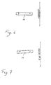
- Figs. 6 and 7 illustrate schematically two different locations of the detector coil in relation to a magnet
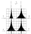
- Fig. 8 shows signals from the detector according to the invention for illustration of its function
- Fig. 9 shows the detector signal with an expanded time scale
- Figs. 10 - 12 show schematically three different types of detecting devices for determining the movement of the coil of the detector according to the invention.
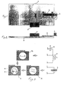
- Figs. 1 - 3 illustrate the construction and function of a magnet position detector according to the invention.
- the detector is provided with a coil 2 mounted at the free end of a piezoelectric bar 4 which is attached to a base 6 at its opposite end.
- the electronic circuitry of the detector is contained in the box 8 also mounted on the base 6.
- the coil is provided with a core having a non-linear B-H curve, preferably a ferrite core which will also give the coil a high inductance.
- the electronic circuitry 8 comprises a current source which through the pins 1 and 2 of the electronic circuitry 8 is connected to the coil 2.
- This current source can supply an adjustable DC current to the coil to adjust the working point of the electrical equipment of the detector.
- This current source can also be operated as a pulse generator delivering electric pulses directly to the coil 2.
- Square pulses are preferably delivered from the electronic circuitry 8 to the coil 2 through a capacitor 10, connected between the pins 2 and 3 of the electronic circuitry 8.
- the capacitor 10 is connected in series with the coil 2 and the value of the capacitor 10 is selected such that the electrical resonance frequency of the electrical circuit will be close to the resonance frequency of the oscillating mechanical system. In this way a maximum coupling is obtained with an efficient energy transfer as a result.
- Pulses delivered by the electronic circuitry 8 are differentiated in the capacitor 10 and the pulse flanks will pass the capacitor and reach the coil 2. If the coil is located in a magnetic field the current passing the coil will excite an oscillation in the piezoelectric bar 4. This oscillation is observed as an electric signal across the piezoelectric bar 4 and supplied to the pins 5 and 6 of the electronic circuitry 8.
- the square pulse will generate a strongly damped electric pulse in the coil 2 with the same polarity as the flanks of the square pulse.
- the oscillations generated by the positive and negative flanks of the square pulse are similar but of opposite directions.
- the coil 2 is preferably provided with a ferrite core as mentioned above.
- Fig. 3 shows the electrical equivalent to the components connected to the electronic circuitry in Figs. 1 and 2 as well as the signals appearing in the circuit.
- Square 12 in figure 3 illustrates pulses generated by a pulse generator in the electronic circuitry 8 and fed to the coil 2 through the capacitor 10.
- the pulse train is also fed to an oscilloscope 16 which on channel 1 (Ch 1) shows a pulse with an expanded time scale as compared to the pulses shown in square 12.
- the pulses supplied to the coil 2 produce an oscillation of the piezoelectric bar 4 in the presence of a magnetic field.
- the oscillations of the piezoelectric element give rise to a corresponding electric signal delivered to the pins 5 and 6 of the electronic circuitry 8.
- the signal from the piezoelectric bar 4 is high pass filtered, square 14, and supplied to channel 2 (Ch 2) of the oscilloscope, square 16.
- channel 2 (Ch 2) of the oscilloscope, square 16 As appears from the oscillogram a damped oscillation of the piezoelectric bar is produced by the two flanks of the pulse, the oscillations at the positive and negative pulse flanks being in opposite phase.
- Figs. 4 and 5 show an advantageous construction of the mounting of the coil 2 on the resilient member.
- the resilient member is formed of a U-shaped sheet 18, the coil 2 being mounted inside the U-shape at the free end portion of the upper shank in the figures of the U-shaped member.
- the resilient member is attached to a base or carrier (not shown in Figs. 4 and 5) at the end portion of the lower shank in Figs. 4 and 5.
- the sheet 18 is formed of a resilient metallic material, like stainless steel, bronze, titanium, or a plastic material.
- a piezoelectric sheet 20 is fixed over the bends 22, 24 and the web of the U-member.
- the embodiment shown in Figs. 4 and 5 is more flexible than the construction with a straight bar shown in Figs. 1 and 2 and results in a lower resonance frequency for essentially the same dimensions of the mechanical system. Further a larger bending, essentially in the bends 22, 24, is obtained in this embodiment when the coil is tilting.
- the piezoelectric element 20 delivers a corresponding electric signal to the electronic circuitry 8 and in this way a more sensitive detector is obtained.
- a permanent magnet 26 is shown with its south pole directed towards the coil.
- the coil 2 is centered on the symmetry axis illustrated with the arrow 28.
- the coil 2 is fed with current such that it has a north pole at its upper end and its south pole at the lower end and in Fig. 5 the current and consequently the poles of the coil 2 are reversed.
- the arrows 30 and 32 above and below the coil 2 respectively illustrate forces which are acting on the coil because of the magnet 26.
- the coil 2 is affected by oppositely directed forces in Figs. 4 and 5 which will tilt the coil 2 in different directions.
- Correspondingly different electric signals are then delivered by the piezoelectric element 20.
- the polarity of the magnet can be determined.
- the coil When determining the position of a magnet 34 in figures 6 and 7 the coil shall preferably be perpendicular to the magnet 34. A maximum signal is obtained from the detector when the coil is centered on the symmetry axis of the magnet 34. This position is schematically shown in Fig. 6.
- FIG. 7 the coil is displaced a distance from the axis and in this position of the coil the oscillations excited by the positive and negative flanks of the current pulse will be different and signals of different strength will be delivered by the detector because of the non-linear B-H curve of the coil core.
- Channel 1 (Ch 1) of the oscillogram in Fig. 8 shows the signal with the coil displaced in relation to the symmetry axis of the magnet 34 as the signals generated by the two flanks of the excitation pulse are of different strength.
- the signals generated by the two pulse flanks are marked by the arrows 36 and 38.
- the signals on channel 2 (Ch 2) of the oscillogram illustrates a situation where the coil 2 is centered on the symmetry axis of the magnet 34. As appears from the oscillogram the signals produced by the two pulse flanks are equal in this case.
- the detector according to the invention it is possible to detect small displacements from the magnet symmetry axis, and consequently to control and localize the position of a magnet.
- Fig. 9 shows the signal of channel 2 in Fig. 8 with an expanded time scale.
- This oscillogram shows that the oscillation frequency is of the order of 400 Hz in this particular case.
- Fig. 10 illustrates alternative means for detecting the oscillations of the coil 2.
- the outer surface 40 of the shank of the flexible member 18 on which the coil 2 is mounted is provided with a reflector or formed as a reflecting surface.
- a light source 42 preferably a laser, is directing a light beam towards the reflecting surface 40 and the reflected beam is recorded by suitable recording means or recording medium 46.
- the reflected beam will create a luminous point 44 on the recording medium 46 which point will describe the oscillation of the coil 2 and the shank on which it is mounted.
- Fig. 11 illustrates an embodiment in which the oscillation of the coil 2 and the flexible member 18 is detected by interference technique.
- the outer side of the shank on which the coil 2 is mounted is provided with a reflector or a reflecting surface 40.
- a monochromatic light source 48 is directing a light beam towards the reflecting surface 40 and the interference pattern 50 produced by the direct incoming light and the reflected light will reproduce the oscillation of the coil 2 and the flexible member 18.
- the interference pattern 50 is recorded on a suitable recording medium 52. The appearance of the interference pattern 50 will be determined by the tilting of the coil 2 and consequently be used as a measure of the tilting and thus the magnetic field strength.
- Fig. 12 illustrates a further alternative means for detecting the movement of the coil 2 and the flexible member 18 comprising a variable capacitance device.
- the capacitance device comprises one essentially stationary condenser plate 54 (the fixation of the plate 54 not shown in the figure) and one condenser plate 56 mounted on the shank of the U-shaped member 18 which is carrying the coil 2.
- the condenser plate 56 will move together with the coil 2 and the resulting variation in the distance d between the two condenser plates 54 and 56 will result in a capacitance which is varying in response to the movement of the coil 2.
- This capacitance will consequently be a measure of the magnetic field measured by the detector.
- the lower shank of the U-shaped member 18 can form the fixed plate 58 of the variable capacitance device, cf figure 12.
- the detector according to the invention can be used to detect both position and polarity of a magnet it has several applications.
- the detector can be used to detect the presence of a magnet and its position.
- a magnet is often used for testing purposes.
- the battery status can for instance be detected by application of a magnet.
- the exact location of the implanted device can often be difficult to determine and therefore also the correct location of the magnet in relation to e.g. the reed switch of an implanted pacemaker. This problem can be solved by the detector according to the invention which makes it possible to determine the best position of the magnet.
- the detector according to the invention can, however, be used as a more general position indicator and the detector can be used to guide an object along a predetermined path, e.g. towards a target.
Landscapes
- Physics & Mathematics (AREA)
- General Physics & Mathematics (AREA)
- Condensed Matter Physics & Semiconductors (AREA)
- Measurement Of Length, Angles, Or The Like Using Electric Or Magnetic Means (AREA)
- Measuring Magnetic Variables (AREA)
- Geophysics And Detection Of Objects (AREA)
- Electrotherapy Devices (AREA)
Description
- The present invention relates to a magnet position detector, particularly for implantable medical apparatuses, comprising a resiliently supported coil, a current source delivering a current to said coil, and a detecting device for detecting the movement of the coil in a magnetic field when fed with an electric current from the current source.
- US-A-4,887,032 discloses a sensor for measurement of position or sense the passage of an object past a point which sensor comprises a flexible bar member provided with a piezoelectric element which bar at its free end supports a coil and is fixed at the opposite end. If the coil is located in a magnetic field it will move if a current is passed through the coil and this movement of the coil will cause the piezoelectric bar to flex and a corresponding voltage will be produced by the associated piezoelectric element. This sensor is used for measuring the distance from an object to a reference point or the rate at which an object passes a reference point to which object a magnet is attached or the object is formed of a material of magnetic permeability and is moving in a permanent magnetic field.
- The purpose of the present invention is to provide a magnet position detector for determining and controlling the position of a magnet.
- This purpose is obtained with a magnet position detector of the kind defined in the introduction of the description and with the characterizing features of
claim 1. - As current pulses are fed to the coil of the detector according to the invention oscillations of the mechanical system carrying the coil are generated at the positive and the negative flanks of the pulse and these oscillations are similar but of opposite phase. If the coil is placed on the axis of the magnet the oscillation amplitudes are equal but if the coil is offset the amplitude is larger on one flank than on the other as a result of the non-linear B-H curve of the core of the coil. If the magnet is turned 180° the larger and smaller amplitudes will change place. Thus the detector according to the invention can be used to detect displacements from the axis of the magnet, and thus used for e.g. control of the position of a magnet, and also for identification of magnet poles. The coil has preferably a ferrite core.
- According to one advantageous embodiment of the detector according to the invention the coil is supported by a resilient bar member which is piezoelectric or is provided with a piezoelectric element delivering an electric signal representative of the bending of the member and thus of the movement of the coil.
- If the resilient member supporting the coil is bent to form at least two shanks interconnected at one end a mechanically more flexible construction is obtained. The improved flexibility results in a lower mechanical resonance frequency for the same dimensions of the device, which is an advantage, and a larger bending of the supporting member is obtained when the coil is tilted. If e.g. a piezoelectric element is applied to the resilient member over the bend to give an electric signal representative of the bending of the member this construction gives a higher sensitivity.
- According to an advantageous further development of the detector according to the invention the resilient member supporting the coil is bent into a U-shape with the coil mounted inside the U-shaped member. Thus in this embodiment the resilient member comprises two bending knees which still further improves the sensitivity of the detector.
- According to another advantageous embodiment of the detector according to the invention the detecting device comprises a light source directing a light beam towards a reflector fixed to the coil and means for recording the movement of the reflected light beam. If the recording means is situated at a long distance from the reflector of the coil, the coil movement will be translated into large readings at the recording means. Thus a detecting device with a high sensitivity is realized.
- According to further embodiments of the detector according to the invention the detecting device can comprise means for recording the interference pattern produced by incoming and reflected light to determine the movement of the coil from this pattern or the detecting device can comprise a variable capacitance device of the kind used in e.g. capacitive microphones.
- According to still another advantageous embodiment of the detector according to the invention the capacitor is selected such that the electrical resonance frequency obtained with the inductance of the coil agrees with the mechanical resonance frequency of the system carrying the coil. An efficient transfer of energy will then be possible, that is, a maximum efficiency is obtained. This is of particular importance when using the detector according to the invention in for instance a pacemaker where no circuit is allowed to have a current consumption exceeding 1 µA.
- According to another advantageous further development of the detector according to the invention the current source is supplying an adjustable DC current to the coil in addition to the current pulses. This DC current results in a new working point and in this way the electrical resonance frequency can be adjusted.
- As examples chosen embodiments of the detector according to the invention will now be described more in detail with reference to the enclosed drawings, on which Fig. 1 shows an elevation view and Fig. 2 a side view of a first embodiment of a magnet position detector according to the invention based on the principle of a moving coil, Fig. 3 shows equivalent electrical circuits of the detector together with electric signals used in its operation, Figs. 4 and 5 show another coil assembly of the detector according to the invention, Figs. 6 and 7 illustrate schematically two different locations of the detector coil in relation to a magnet, Fig. 8 shows signals from the detector according to the invention for illustration of its function, Fig. 9 shows the detector signal with an expanded time scale and Figs. 10 - 12 show schematically three different types of detecting devices for determining the movement of the coil of the detector according to the invention.
- Figs. 1 - 3 illustrate the construction and function of a magnet position detector according to the invention. The detector is provided with a
coil 2 mounted at the free end of a piezoelectric bar 4 which is attached to abase 6 at its opposite end. The electronic circuitry of the detector is contained in the box 8 also mounted on thebase 6. The coil is provided with a core having a non-linear B-H curve, preferably a ferrite core which will also give the coil a high inductance. - The electronic circuitry 8 comprises a current source which through the
pins coil 2. This current source can supply an adjustable DC current to the coil to adjust the working point of the electrical equipment of the detector. This current source can also be operated as a pulse generator delivering electric pulses directly to thecoil 2. - Square pulses are preferably delivered from the electronic circuitry 8 to the
coil 2 through acapacitor 10, connected between thepins 2 and 3 of the electronic circuitry 8. - The
capacitor 10 is connected in series with thecoil 2 and the value of thecapacitor 10 is selected such that the electrical resonance frequency of the electrical circuit will be close to the resonance frequency of the oscillating mechanical system. In this way a maximum coupling is obtained with an efficient energy transfer as a result. - Pulses delivered by the electronic circuitry 8 are differentiated in the
capacitor 10 and the pulse flanks will pass the capacitor and reach thecoil 2. If the coil is located in a magnetic field the current passing the coil will excite an oscillation in the piezoelectric bar 4. This oscillation is observed as an electric signal across the piezoelectric bar 4 and supplied to thepins - Because of the above mentioned resonance the square pulse will generate a strongly damped electric pulse in the
coil 2 with the same polarity as the flanks of the square pulse. Thus the oscillations generated by the positive and negative flanks of the square pulse are similar but of opposite directions. - To get a sufficiently high inductance the
coil 2 is preferably provided with a ferrite core as mentioned above. Typical figures of the components are inductance L = 350 mH, resistance R = 1 kohm, capacitance C = 150 nF and square pulses are delivered with a frequency of the order of 1 - 10 Hz. - Fig. 3 shows the electrical equivalent to the components connected to the electronic circuitry in Figs. 1 and 2 as well as the signals appearing in the circuit.
-
Square 12 in figure 3 illustrates pulses generated by a pulse generator in the electronic circuitry 8 and fed to thecoil 2 through thecapacitor 10. - The pulse train is also fed to an
oscilloscope 16 which on channel 1 (Ch 1) shows a pulse with an expanded time scale as compared to the pulses shown insquare 12. - The pulses supplied to the
coil 2 produce an oscillation of the piezoelectric bar 4 in the presence of a magnetic field. The oscillations of the piezoelectric element give rise to a corresponding electric signal delivered to thepins square 14, and supplied to channel 2 (Ch 2) of the oscilloscope,square 16. As appears from the oscillogram a damped oscillation of the piezoelectric bar is produced by the two flanks of the pulse, the oscillations at the positive and negative pulse flanks being in opposite phase. - Figs. 4 and 5 show an advantageous construction of the mounting of the
coil 2 on the resilient member. In this embodiment the resilient member is formed of a U-shapedsheet 18, thecoil 2 being mounted inside the U-shape at the free end portion of the upper shank in the figures of the U-shaped member. The resilient member is attached to a base or carrier (not shown in Figs. 4 and 5) at the end portion of the lower shank in Figs. 4 and 5. - The
sheet 18 is formed of a resilient metallic material, like stainless steel, bronze, titanium, or a plastic material. - On the outer side of the U-shaped member a
piezoelectric sheet 20 is fixed over thebends - The embodiment shown in Figs. 4 and 5 is more flexible than the construction with a straight bar shown in Figs. 1 and 2 and results in a lower resonance frequency for essentially the same dimensions of the mechanical system. Further a larger bending, essentially in the
bends piezoelectric element 20 delivers a corresponding electric signal to the electronic circuitry 8 and in this way a more sensitive detector is obtained. - To the left in Figs. 4 and 5 a permanent magnet 26 is shown with its south pole directed towards the coil. The
coil 2 is centered on the symmetry axis illustrated with thearrow 28. In Fig. 4 thecoil 2 is fed with current such that it has a north pole at its upper end and its south pole at the lower end and in Fig. 5 the current and consequently the poles of thecoil 2 are reversed. Thearrows coil 2 respectively illustrate forces which are acting on the coil because of the magnet 26. As appears thecoil 2 is affected by oppositely directed forces in Figs. 4 and 5 which will tilt thecoil 2 in different directions. Correspondingly different electric signals are then delivered by thepiezoelectric element 20. Thus with the detector according to the invention the polarity of the magnet can be determined. - When determining the position of a
magnet 34 in figures 6 and 7 the coil shall preferably be perpendicular to themagnet 34. A maximum signal is obtained from the detector when the coil is centered on the symmetry axis of themagnet 34. This position is schematically shown in Fig. 6. - In Fig. 7 the coil is displaced a distance from the axis and in this position of the coil the oscillations excited by the positive and negative flanks of the current pulse will be different and signals of different strength will be delivered by the detector because of the non-linear B-H curve of the coil core. This is illustrated in Fig. 8. Channel 1 (Ch 1) of the oscillogram in Fig. 8 shows the signal with the coil displaced in relation to the symmetry axis of the
magnet 34 as the signals generated by the two flanks of the excitation pulse are of different strength. The signals generated by the two pulse flanks are marked by thearrows coil 2 is centered on the symmetry axis of themagnet 34. As appears from the oscillogram the signals produced by the two pulse flanks are equal in this case. - Thus with the detector according to the invention it is possible to detect small displacements from the magnet symmetry axis, and consequently to control and localize the position of a magnet.
- Fig. 9 shows the signal of
channel 2 in Fig. 8 with an expanded time scale. This oscillogram shows that the oscillation frequency is of the order of 400 Hz in this particular case. - Fig. 10 illustrates alternative means for detecting the oscillations of the
coil 2. Theouter surface 40 of the shank of theflexible member 18 on which thecoil 2 is mounted is provided with a reflector or formed as a reflecting surface. Alight source 42, preferably a laser, is directing a light beam towards the reflectingsurface 40 and the reflected beam is recorded by suitable recording means orrecording medium 46. Thus the reflected beam will create aluminous point 44 on therecording medium 46 which point will describe the oscillation of thecoil 2 and the shank on which it is mounted. - Fig. 11 illustrates an embodiment in which the oscillation of the
coil 2 and theflexible member 18 is detected by interference technique. Also in this case the outer side of the shank on which thecoil 2 is mounted is provided with a reflector or a reflectingsurface 40. A monochromaticlight source 48 is directing a light beam towards the reflectingsurface 40 and theinterference pattern 50 produced by the direct incoming light and the reflected light will reproduce the oscillation of thecoil 2 and theflexible member 18. Theinterference pattern 50 is recorded on asuitable recording medium 52. The appearance of theinterference pattern 50 will be determined by the tilting of thecoil 2 and consequently be used as a measure of the tilting and thus the magnetic field strength. - Fig. 12 illustrates a further alternative means for detecting the movement of the
coil 2 and theflexible member 18 comprising a variable capacitance device. The capacitance device comprises one essentially stationary condenser plate 54 (the fixation of theplate 54 not shown in the figure) and onecondenser plate 56 mounted on the shank of theU-shaped member 18 which is carrying thecoil 2. Thus when thecoil 2 is moving thecondenser plate 56 will move together with thecoil 2 and the resulting variation in the distance d between the twocondenser plates coil 2. This capacitance will consequently be a measure of the magnetic field measured by the detector. - Instead of using a separate
fix condenser plate 54 the lower shank of theU-shaped member 18 can form the fixedplate 58 of the variable capacitance device, cf figure 12. - As the detector according to the invention can be used to detect both position and polarity of a magnet it has several applications.
- In the medical field the detector can be used to detect the presence of a magnet and its position. For implanted medical devices, like pacemakers, a magnet is often used for testing purposes. Thus the battery status can for instance be detected by application of a magnet. The exact location of the implanted device can often be difficult to determine and therefore also the correct location of the magnet in relation to e.g. the reed switch of an implanted pacemaker. This problem can be solved by the detector according to the invention which makes it possible to determine the best position of the magnet.
- The detector according to the invention can, however, be used as a more general position indicator and the detector can be used to guide an object along a predetermined path, e.g. towards a target.
Claims (14)
- A magnet position detector, particularly for implantable medical apparatuses, comprising a resiliently supported coil (2), a current source (8) delivering a current to said coil, and a detecting device (20; 40, 42, 44, 46; 48, 50, 52; 54, 56) for detecting the movement of the coil in a magnetic field when fed with an electric current from the current source, characterized in that the coil (2) has a core with a non-linear B-H curve and in that the current source is a pulse source (8) arranged to deliver current pulses with at least one positive and one negative flank, said detecting device (20; 40, 42, 44, 46; 48, 50, 52; 54, 56) being arranged to detect the movements of the coil (2) excited by positive and negative flanks respectively of delivered current pulses and to compare the magnitudes of the movements.
- The detector according to claim 1, characterized in that the coil (2) has a ferrite core.
- The detector according to claim 1 or 2, characterized in that the coil (2) is supported by a resilient bar member (4; 18) which is piezoelectric or is provided with a piezoelectric element (20) for delivering an electric signal representative of a bending of the member and thus of a movement of the coil.
- The detector according to claim 3, characterized in that said resilient member (18) is bent to form at least two shanks interconnected at one end, said coil (2) being mounted at the free end of one of the shanks and said resilient member being fixed at the free end portion of the other shank.
- The detector according to claim 4, characterized in that the piezoelectric element (20) is applied to the resilient member (18) over the bend (22, 24) to give an electric signal representative of a bending of the member and thus of a movement of the coil (2).
- The detector according to claim 5, characterized in that said resilient member (18) is bent into a U-shape and in that said coil (2) is mounted inside the U-shaped member at the free end of one of the shanks of the U-shape, said U-shaped member being fixed at the free end portion of its other shank.
- The detector according to claim 5 and 6, characterized in that said piezoelectric element is formed as a sheet (20) of piezoelectric material applied to the outer side of the U-shaped member (18) over its bends (22, 24) and its web.
- The detector according to any one of the claims 1 - 7, characterized in that said detecting device comprises a light source (42) directing a light beam towards a reflector (40) fixed to the coil (2) and means (46) for recording the movement of the reflected light beam.
- The detector according to any one of the claims 1 - 7, characterized in that said detecting device comprises a monochromatic light source (48) directing a light beam towards a reflector (40) fixed to the coil (2) and means (52) for recording the interference pattern (50) produced by incoming and reflected light to determine a movement of the coil from the interference pattern.
- The detector according to any one of the claims 1 - 7, characterized in that said detecting device comprises a variable capacitance device having one stationary condenser plate (54, 58) and one condenser plate (56) coupled to the coil (2) for moving together with it.
- The detector according to any one of the claims 1 - 10, characterized in that the current pulses are square pulses supplied by the current source to the coil (2) through a capacitor (10).
- The detector according to claim 11, characterized in that said detecting device comprises indicator means (16) for indicating the oscillations of the coil (2) excited by the positive and negative flanks respectively of the square pulse for comparison of the amplitudes of the oscillations excited by the two flanks.
- The detector according to claim 11 or 12, characterized in that the capacitance value of the capacitor (10) is selected such that the electrical resonance frequency obtained together with the inductance of the coil (2) agrees with the mechanical resonance frequency for the mounted coil.
- The detector according to any one of the claims 1 - 13, characterized in that the current source (8) is arranged to supply an adjustable DC current to the coil (2) in addition to the current pulses.
Priority Applications (4)
| Application Number | Priority Date | Filing Date | Title |
|---|---|---|---|
| DE69216830T DE69216830T2 (en) | 1992-09-29 | 1992-09-29 | Magnetic position detector |
| EP92116650A EP0590179B1 (en) | 1992-09-29 | 1992-09-29 | Magnet position detector |
| US08/124,450 US5541507A (en) | 1992-09-29 | 1993-09-22 | Device for detecting the position of a magnet by analyzing movement of a current-fed coil disposed in the magnetic field of the magnet |
| JP24254593A JPH06213984A (en) | 1992-09-29 | 1993-09-29 | Position detector of magnet |
Applications Claiming Priority (1)
| Application Number | Priority Date | Filing Date | Title |
|---|---|---|---|
| EP92116650A EP0590179B1 (en) | 1992-09-29 | 1992-09-29 | Magnet position detector |
Publications (2)
| Publication Number | Publication Date |
|---|---|
| EP0590179A1 EP0590179A1 (en) | 1994-04-06 |
| EP0590179B1 true EP0590179B1 (en) | 1997-01-15 |
Family
ID=8210071
Family Applications (1)
| Application Number | Title | Priority Date | Filing Date |
|---|---|---|---|
| EP92116650A Expired - Lifetime EP0590179B1 (en) | 1992-09-29 | 1992-09-29 | Magnet position detector |
Country Status (4)
| Country | Link |
|---|---|
| US (1) | US5541507A (en) |
| EP (1) | EP0590179B1 (en) |
| JP (1) | JPH06213984A (en) |
| DE (1) | DE69216830T2 (en) |
Families Citing this family (6)
| Publication number | Priority date | Publication date | Assignee | Title |
|---|---|---|---|---|
| FR2806808B1 (en) * | 2000-03-24 | 2002-05-24 | Ela Medical Sa | CIRCUIT FOR DETECTING THE PRESENCE OF A PERMANENT MAGNET IN THE VICINITY OF AN ACTIVE MEDICAL DEVICE, IN PARTICULAR A CARDIAC PACEMAKER, DEFIBRILLATOR, CARDIOVERTER AND/OR MULTI-SITE DEVICE |
| DE102004062399B4 (en) * | 2004-12-23 | 2009-02-05 | Siemens Ag | Implantable pacemaker |
| US7971487B2 (en) * | 2008-05-02 | 2011-07-05 | Carlen Controls, Inc. | Linear position transducer with wireless read head |
| US9404556B2 (en) | 2013-03-12 | 2016-08-02 | Waukesha Bearings Corporation | Damper |
| CN115050536B (en) * | 2022-07-19 | 2023-10-27 | 南京航空航天大学 | Bistable electromagnet |
| CN117398118A (en) * | 2023-12-11 | 2024-01-16 | 上海奕瑞光电子科技股份有限公司 | Wireless positioning method, device, electronic product and medium of mobile DR |
Family Cites Families (15)
| Publication number | Priority date | Publication date | Assignee | Title |
|---|---|---|---|---|
| US2452156A (en) * | 1945-09-24 | 1948-10-26 | Donald S Schover | Float position indicator |
| US3898555A (en) * | 1973-12-19 | 1975-08-05 | Tempo Instr Inc | Linear distance measuring device using a moveable magnet interacting with a sonic waveguide |
| US4344068A (en) * | 1979-05-29 | 1982-08-10 | International Business Machines Corporation | Coding schemes for acoustic delay line data collection system |
| US4721902A (en) * | 1985-07-08 | 1988-01-26 | Mts Systems Corporation | Noise rejection in a sonic transducer |
| GB8623435D0 (en) * | 1986-09-30 | 1986-11-05 | Squire P T | Magnetic field sensor |
| DE3734128A1 (en) * | 1987-10-09 | 1989-04-27 | Fraunhofer Ges Forschung | MAGNETOMETER |
| US4931729A (en) * | 1987-12-22 | 1990-06-05 | Allied-Signal Inc. | Method and apparatus for measuring strain or fatigue |
| US4887032A (en) * | 1988-05-02 | 1989-12-12 | Ford Motor Company | Resonant vibrating structure with electrically driven wire coil and vibration sensor |
| US5036286A (en) * | 1988-06-03 | 1991-07-30 | The Research Corporation Of The University Of Hawaii | Magnetic and electric force sensing method and apparatus |
| WO1990000030A1 (en) * | 1988-07-01 | 1990-01-11 | Koch Elektronik + Apparatebau Ag | Measurement probe for locating metallic objects in the human or animal body |
| US4931732A (en) * | 1988-07-25 | 1990-06-05 | Cornell Research Foundation, Inc. | Magnetic flexure system for determining superconductive properties of a sample |
| US5142227A (en) * | 1990-06-04 | 1992-08-25 | Allied-Signal Inc. | Method and apparatus for measuring strain within a ferromagnetic material by sensing change in coercive field |
| US5146165A (en) * | 1991-01-09 | 1992-09-08 | Brown Rork S | Pressure measuring device responsible to a magnetic flux field |
| US5136884A (en) * | 1991-04-17 | 1992-08-11 | Mts Systems Corporation | Magnetic sight gage sensor |
| EP0529122B1 (en) * | 1991-08-26 | 1995-11-08 | Pacesetter AB | Magnetic-field sensor |
-
1992
- 1992-09-29 DE DE69216830T patent/DE69216830T2/en not_active Expired - Fee Related
- 1992-09-29 EP EP92116650A patent/EP0590179B1/en not_active Expired - Lifetime
-
1993
- 1993-09-22 US US08/124,450 patent/US5541507A/en not_active Expired - Lifetime
- 1993-09-29 JP JP24254593A patent/JPH06213984A/en active Pending
Also Published As
| Publication number | Publication date |
|---|---|
| US5541507A (en) | 1996-07-30 |
| EP0590179A1 (en) | 1994-04-06 |
| JPH06213984A (en) | 1994-08-05 |
| DE69216830D1 (en) | 1997-02-27 |
| DE69216830T2 (en) | 1997-09-04 |
Similar Documents
| Publication | Publication Date | Title |
|---|---|---|
| JP3246727B2 (en) | Inductive electronic caliper | |
| US5424642A (en) | Magnetic field detector with a resiliently mounted electrical coil | |
| KR100830853B1 (en) | Metal immune system | |
| US4602639A (en) | Method and apparatus for contactless measurement of charge concentrations and potential differences in biological organisms | |
| CN114269237A (en) | Tracking system and marking device to be tracked by the tracking system | |
| US4887032A (en) | Resonant vibrating structure with electrically driven wire coil and vibration sensor | |
| EP0560513A2 (en) | Single balanced beam electrostatic voltmeter modulator | |
| JPH10318781A (en) | Guide type position detector | |
| US4314202A (en) | Flexural vibration sensor with magnetic field generating and sensing | |
| US5391001A (en) | Thermometer for remote temperature measurements | |
| US6049204A (en) | Electronic linear scale using a reduced offset high accuracy induced current position transducer | |
| EP0590179B1 (en) | Magnet position detector | |
| EP1298457B1 (en) | Inductive sensor arrangement and method for detecting of ferrous metal objects | |
| US4383535A (en) | Method for preventing remanence phenomena from interfering with magnetic field sensing systems and a device for implementation of the method | |
| US5841275A (en) | Magnetic measuring system having a particularly oriented auxiliary field | |
| WO1999050690A2 (en) | Position sensing | |
| CN113804284B (en) | Vibration displacement measuring method of vibration type viscoelastic sensor | |
| US5243292A (en) | Electrostatic measuring tuning fork and means for limiting mechanical amplitude thereof | |
| US6639403B2 (en) | System and method for sensing magnetic fields based on movement | |
| EP0274450A2 (en) | A device for measuring the proximity of a metal object | |
| EP4014856A1 (en) | Passive wireless coil-based markers and sensor compatible with a medical readout system for tracking magneto-mechanical oscillators | |
| SU881628A1 (en) | Electrostatic field pickup | |
| JP3272232B2 (en) | Vibration displacement detector | |
| JP3346429B2 (en) | Magnetostriction measuring device | |
| US4471303A (en) | Flexural vibration transducer with magnetic field generating |
Legal Events
| Date | Code | Title | Description |
|---|---|---|---|
| PUAI | Public reference made under article 153(3) epc to a published international application that has entered the european phase |
Free format text: ORIGINAL CODE: 0009012 |
|
| AK | Designated contracting states |
Kind code of ref document: A1 Designated state(s): DE FR GB IT NL SE |
|
| 17P | Request for examination filed |
Effective date: 19940504 |
|
| RAP1 | Party data changed (applicant data changed or rights of an application transferred) |
Owner name: PACESETTER AB |
|
| GRAG | Despatch of communication of intention to grant |
Free format text: ORIGINAL CODE: EPIDOS AGRA |
|
| 17Q | First examination report despatched |
Effective date: 19960311 |
|
| GRAH | Despatch of communication of intention to grant a patent |
Free format text: ORIGINAL CODE: EPIDOS IGRA |
|
| GRAH | Despatch of communication of intention to grant a patent |
Free format text: ORIGINAL CODE: EPIDOS IGRA |
|
| GRAA | (expected) grant |
Free format text: ORIGINAL CODE: 0009210 |
|
| AK | Designated contracting states |
Kind code of ref document: B1 Designated state(s): DE FR GB IT NL SE |
|
| REF | Corresponds to: |
Ref document number: 69216830 Country of ref document: DE Date of ref document: 19970227 |
|
| ITF | It: translation for a ep patent filed |
Owner name: 0414;07MIFSTUDIO JAUMANN |
|
| PG25 | Lapsed in a contracting state [announced via postgrant information from national office to epo] |
Ref country code: SE Effective date: 19970415 |
|
| ET | Fr: translation filed | ||
| PLBE | No opposition filed within time limit |
Free format text: ORIGINAL CODE: 0009261 |
|
| STAA | Information on the status of an ep patent application or granted ep patent |
Free format text: STATUS: NO OPPOSITION FILED WITHIN TIME LIMIT |
|
| 26N | No opposition filed | ||
| PGFP | Annual fee paid to national office [announced via postgrant information from national office to epo] |
Ref country code: GB Payment date: 19980903 Year of fee payment: 7 |
|
| PG25 | Lapsed in a contracting state [announced via postgrant information from national office to epo] |
Ref country code: GB Free format text: LAPSE BECAUSE OF NON-PAYMENT OF DUE FEES Effective date: 19990929 |
|
| PGFP | Annual fee paid to national office [announced via postgrant information from national office to epo] |
Ref country code: NL Payment date: 19990930 Year of fee payment: 8 |
|
| GBPC | Gb: european patent ceased through non-payment of renewal fee |
Effective date: 19990929 |
|
| PG25 | Lapsed in a contracting state [announced via postgrant information from national office to epo] |
Ref country code: NL Free format text: LAPSE BECAUSE OF NON-PAYMENT OF DUE FEES Effective date: 20010401 |
|
| NLV4 | Nl: lapsed or anulled due to non-payment of the annual fee |
Effective date: 20010401 |
|
| PGFP | Annual fee paid to national office [announced via postgrant information from national office to epo] |
Ref country code: FR Payment date: 20050831 Year of fee payment: 14 |
|
| PGFP | Annual fee paid to national office [announced via postgrant information from national office to epo] |
Ref country code: DE Payment date: 20050927 Year of fee payment: 14 |
|
| PG25 | Lapsed in a contracting state [announced via postgrant information from national office to epo] |
Ref country code: DE Free format text: LAPSE BECAUSE OF NON-PAYMENT OF DUE FEES Effective date: 20070403 |
|
| REG | Reference to a national code |
Ref country code: FR Ref legal event code: ST Effective date: 20070531 |
|
| PG25 | Lapsed in a contracting state [announced via postgrant information from national office to epo] |
Ref country code: FR Free format text: LAPSE BECAUSE OF NON-PAYMENT OF DUE FEES Effective date: 20061002 |
|
| PGFP | Annual fee paid to national office [announced via postgrant information from national office to epo] |
Ref country code: IT Payment date: 20090919 Year of fee payment: 18 |
|
| PG25 | Lapsed in a contracting state [announced via postgrant information from national office to epo] |
Ref country code: IT Free format text: LAPSE BECAUSE OF NON-PAYMENT OF DUE FEES Effective date: 20100929 |