EP0588687B1 - System for determining at least one control parameter for vehicular traffic - Google Patents
System for determining at least one control parameter for vehicular traffic Download PDFInfo
- Publication number
- EP0588687B1 EP0588687B1 EP93402175A EP93402175A EP0588687B1 EP 0588687 B1 EP0588687 B1 EP 0588687B1 EP 93402175 A EP93402175 A EP 93402175A EP 93402175 A EP93402175 A EP 93402175A EP 0588687 B1 EP0588687 B1 EP 0588687B1
- Authority
- EP
- European Patent Office
- Prior art keywords
- vehicle
- radar
- speed
- elevation
- calculating
- Prior art date
- Legal status (The legal status is an assumption and is not a legal conclusion. Google has not performed a legal analysis and makes no representation as to the accuracy of the status listed.)
- Expired - Lifetime
Links
Images


Classifications
-
- G—PHYSICS
- G08—SIGNALLING
- G08G—TRAFFIC CONTROL SYSTEMS
- G08G1/00—Traffic control systems for road vehicles
- G08G1/01—Detecting movement of traffic to be counted or controlled
-
- G—PHYSICS
- G01—MEASURING; TESTING
- G01S—RADIO DIRECTION-FINDING; RADIO NAVIGATION; DETERMINING DISTANCE OR VELOCITY BY USE OF RADIO WAVES; LOCATING OR PRESENCE-DETECTING BY USE OF THE REFLECTION OR RERADIATION OF RADIO WAVES; ANALOGOUS ARRANGEMENTS USING OTHER WAVES
- G01S13/00—Systems using the reflection or reradiation of radio waves, e.g. radar systems; Analogous systems using reflection or reradiation of waves whose nature or wavelength is irrelevant or unspecified
- G01S13/02—Systems using reflection of radio waves, e.g. primary radar systems; Analogous systems
- G01S13/50—Systems of measurement based on relative movement of target
- G01S13/58—Velocity or trajectory determination systems; Sense-of-movement determination systems
- G01S13/64—Velocity measuring systems using range gates
-
- G—PHYSICS
- G01—MEASURING; TESTING
- G01S—RADIO DIRECTION-FINDING; RADIO NAVIGATION; DETERMINING DISTANCE OR VELOCITY BY USE OF RADIO WAVES; LOCATING OR PRESENCE-DETECTING BY USE OF THE REFLECTION OR RERADIATION OF RADIO WAVES; ANALOGOUS ARRANGEMENTS USING OTHER WAVES
- G01S13/00—Systems using the reflection or reradiation of radio waves, e.g. radar systems; Analogous systems using reflection or reradiation of waves whose nature or wavelength is irrelevant or unspecified
- G01S13/88—Radar or analogous systems specially adapted for specific applications
- G01S13/91—Radar or analogous systems specially adapted for specific applications for traffic control
- G01S13/92—Radar or analogous systems specially adapted for specific applications for traffic control for velocity measurement
-
- G—PHYSICS
- G08—SIGNALLING
- G08G—TRAFFIC CONTROL SYSTEMS
- G08G1/00—Traffic control systems for road vehicles
- G08G1/01—Detecting movement of traffic to be counted or controlled
- G08G1/015—Detecting movement of traffic to be counted or controlled with provision for distinguishing between two or more types of vehicles, e.g. between motor-cars and cycles
Definitions
- the present invention consists of a system for calculating at least minus a vehicle traffic control setting.
- the field more particularly targeted by the invention relates to motor vehicles (cars, trucks ...) circulating on all kinds of roads (highways, national, departmental ).
- motor vehicles cars, trucks
- system which is the subject of the invention can also control river or sea traffic, or objects circulating on a robotic chain. So the term vehicle covers just as well cars, trucks, motorcycles, boats, objects ...
- a first widely used technique consists of place induction loops under the road.
- the variation of the field induced in such loops allows to know if a vehicle has passed or no.
- induction loops work regardless of conditions climatic conditions, day and night.
- establishment of these induction loops is cumbersome and expensive to implement, and it is difficult, if not impossible, to conduct interviews.
- a second technique still at the prototype stage consists in use video cameras associated with processing of the captured images.
- the installation on masts of these cameras is very easy here, but the performances are inconclusive: video cameras do not present the advantage of operating whatever the climatic conditions, and are, moreover, very dependent on the light conditions.
- the algorithms used in image processing are complex and require significant computing power.
- a third known technique consists in positioning a radar, for example on a bridge infrastructure, and detect vehicles as well as their speed by the Doppler effect.
- US Patent US-A-4,985,705 describes a way usual to implement this third traffic analysis technique road using a continuous wave radar. This consists of choosing a continuous wave millimeter radar with antenna having a brush end (3 ° opening horizontally and 13 ° vertical), place it in the above a traffic lane, tilted downward, so that the beam of its antenna only intercepts a portion of this traffic lane and extract the different parameters concerning the traffic of detections of vehicle presences on this lane and speeds of these vehicles deduced from the Doppler effect.
- the disadvantage of this implementation is that it allows you to control only one lane of traffic. On a roadway with several traffic lanes, it is necessary to have as many speed cameras and traffic lanes which can be costly as well in switchgear than in installation.
- the object of the present invention is to overcome the drawbacks and respond to a recent request that increasingly more requirements on the control of a localized area which may present several two-way traffic lanes, for example a motorway.
- the present invention relates to a system calculation of at least one vehicle traffic control parameter which can travel on at least two traffic lanes, as described in claim 1.
- processing module of the radar reception signal is provided with an interleaved smoothing filter between the Fourier transform calculation means and the means of detection.
- Figure 1 is an exemplary embodiment of a control according to the invention:
- a first essential characteristic of the system according to the invention is the use of a pulse radar 1.
- a pulse radar 1 generates indeed the distance information of the detected vehicles. This information can be used for the observation of several ways traffic thanks to a single pulse radar, positioned particular way as we will see later.
- the pulse radar 1 can conventionally comprise a pulse generator 10 of carrier frequency f 0 , transmitting the pulses generated to a transmitter 11, the latter delivering pulses of carrier frequency f 0 to an antenna 13 at the frequency of recurrence F R.
- the radar preferably operates in millimeter waves, the frequency f o possibly belonging to the interval [30 GHz; 100 GHz].
- f o close to either 35 GHz or 94 GHz, values for which the atmospheric absorption is the lowest.
- the same antenna 13 receives echo signals which it transmits, via a circulator 14, to a conventional receiver 15.
- Synchronization 16 allows the transmission-reception unit to function properly, i.e. to receive echo signals only when the radar is not pulsing.
- the appearance of the radiation from antenna 13 and its relative position with respect to the channels that you want to control are those shown on the Figures 2a and 2b which are the top and side views respectively radar coverage in the specific but non-limiting application traffic control on a highway 5 comprising for example six taxiways 5a and a central reservation 5b.
- the system 4 is positioned on a side not common to the traffic lanes 5a.
- the system 4 is positioned in height, for example on a mast, so that the antenna 13 of the radar can overhang the tracks 5a of a given height h.
- this height h greater than the maximum possible height of a motorway vehicle, so that there is no possible masking between two vehicles which should be detected at the same time by the radar, in case the one of the two vehicles closest to the radar has a height superior to the other vehicle.
- the radiation pattern 6 must be narrow in bearing ( Figure 2a) and wide enough in site to cover all the tracks ( Figure 2b).
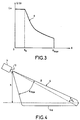
- the radiation diagram in elevation an appearance as shown in FIGS. 2b and 4, for which the diagram 6 has a gain zone 6a dependent on the distance and substantially parallel to the route 5 so that the same vehicle detected at different distances is received with almost the same amplitude by the radar.
- G ( ⁇ ) of gain as a function of the angle in elevation represented by the curve 8 of FIG. 3 has the preceding property.
- the diagram is identical to that of a conventional antenna, that is to say that it has a substantially constant gain G o .
- the echo signals from the receiver 15 of radar 1 are then transmitted to a signal processing module 2 allowing the detection of vehicles by traffic.
- the time samples are then delivered to calculation means 21 of the Fourier transform of these samples, and the samples of frequency from the calculation means 21 are, in accordance with the invention, filtered in amplitude by a smoothing filter 22.
- FIGS. 5a and 5b representing an example of the amplitude of the frequency signal according to the time respectively before filtering 22 and after this filtering, show the need for this filtering.
- Curve 9 in Figure 5a is a example of what is obtained with the system of the invention when only vehicle cuts the diagram, at the output of the calculation means 21 of the Fourier transform.
- This curve 9 presents rapid and significant variations amplitude so that a simple thresholding with respect to a value of given threshold would lead to detecting several vehicles instead of one.
- the amplitude fluctuation illustrated by curve 9 is due to the fluctuation of the radar equivalent surface of the vehicle in waves millimeters to the movement of the vehicle and the change of angle view of this vehicle during its passage through the beam.
- the system according to the invention therefore comprises a smoothing filter 22 of the amplitude of the frequency signal after Fourier transform.
- This filter can for example be a medium filter whose application to a given frequency sample makes it possible to replace the amplitude of this sample by the mean of this amplitude with the amplitudes of an even number of samples taken on either side of said sample given.
- the filtering result is illustrated by the curve 9 ′ in the figure 5b. It is now possible to compare the amplitude of the frequency samples with a given threshold s, thanks to means of comparison 23 illustrated in Figure 1. Each positive comparison is detection of a vehicle on a lane.
- the threshold is either set at advance, be adaptive.
- the system Following the detection of vehicles on each lane from a single radar 1, the system according to the invention provides for calculating one or several traffic parameters. It is equipped for this with a module parameter extraction 3.
- a first example of a parameter to extract is the total number of vehicles per lane or overall detected during a measurement time T TOT . This number can be extracted by means of incrementation 30, connected for example to comparison means 23, and increasing by one unit each time a vehicle is detected.
- the system according to the invention can also extract the length L v of a detected vehicle.
- FIG. 6 shows that it is necessary to make a correction on the length measured by the radar 1. Indeed, the diagram 6 of the radar 1 detects the front of the vehicle A when the latter intercepts the start of the distance box 7 , and detection is carried out until the vehicle leaves this distance box completely. If L cd is the length of the distance box 7, account must be taken of the error it causes.
- n v is the number of vehicles detected over the total duration T TOT , supplied for example by the incrementing means 30, and V i is the speed of a detected vehicle, supplied by the first means 31.
- the signal processing 2 and extraction modules parameters 3 are advantageously implemented in the form of programs IT. Calculations can be done in real time, or in time deferred if the system of storage means is provided 24.
- the performance of the system of the invention is independent of climatic conditions. We can also consider to install several systems on different points of a road or highway, and correlate the results from each system with an information collection station, so as to have a follow-up of traffic development.
- the system can be positioned at points nerve centers of a motorway network (entry or exit ramp, approaching a toll, entering or leaving a rest area ).
Landscapes
- Engineering & Computer Science (AREA)
- Radar, Positioning & Navigation (AREA)
- Remote Sensing (AREA)
- Physics & Mathematics (AREA)
- General Physics & Mathematics (AREA)
- Computer Networks & Wireless Communication (AREA)
- Electromagnetism (AREA)
- Radar Systems Or Details Thereof (AREA)
- Traffic Control Systems (AREA)
Description
La présente invention consiste en un système de calcul d'au moins un paramètre de contrôle de trafic de véhicules.The present invention consists of a system for calculating at least minus a vehicle traffic control setting.
Le domaine plus particulièrement visé par l'invention concerne les véhicules automobiles (voitures, poids lourds...) circulant sur toutes sortes de voies (autoroutes, nationales, départementales...). Nous verrons cependant que le système objet de l'invention peut également contrôler le trafic fluvial ou maritime, ou encore des objets circulant sur une chaíne robotisée. Ainsi, le terme véhicule couvre tout aussi bien les voitures, camions, motocyclettes, bateaux, objets...The field more particularly targeted by the invention relates to motor vehicles (cars, trucks ...) circulating on all kinds of roads (highways, national, departmental ...). We however, we will see that the system which is the subject of the invention can also control river or sea traffic, or objects circulating on a robotic chain. So the term vehicle covers just as well cars, trucks, motorcycles, boats, objects ...
Dans le domaine particulier des véhicules automobiles, on cherche à faire une analyse du trafic en un point précis permettant de déduire un certain nombre de paramètres. Les paramètres auxquels on s'intéresse sont notamment :
- le nombre de véhicules passant sur chaque voie durant un intervalle de temps prédéfini ;
- la vitesse de ces véhicules ;
- la vitesse moyenne et harmonique d'un ensemble de véhicules ;
- le pourcentage de poids lourds ;
- le taux d'occupation sur chacune des voies...
- the number of vehicles passing through each lane during a predefined time interval;
- the speed of these vehicles;
- the average and harmonic speed of a set of vehicles;
- the percentage of heavy goods vehicles;
- the occupancy rate on each channel ...
A l'heure actuelle, l'analyse du trafic routier ou autoroutier est réalisée principalement par trois techniques :At present, the analysis of road or motorway traffic is mainly performed by three techniques:
Une première technique très largement utilisée consiste à placer sous la route des boucles à induction. La variation du champ induit dans de telles boucles permet de savoir si un véhicule est passé ou non.A first widely used technique consists of place induction loops under the road. The variation of the field induced in such loops allows to know if a vehicle has passed or no.
L'avantage principal de cette technique réside dans le fait que les boucles à induction fonctionnent quelles que soient les conditions climatiques, de jour comme de nuit. Cependant, l'implantation de ces boucles à induction est lourde et coûteuse à mettre en oeuvre, et il est difficile, voire impossible de procéder à des entretiens. De plus, on ne peut guère faire mieux que du comptage de voitures.The main advantage of this technique is that induction loops work regardless of conditions climatic conditions, day and night. However, the establishment of these induction loops is cumbersome and expensive to implement, and it is difficult, if not impossible, to conduct interviews. Furthermore, we cannot hardly do better than counting cars.
Une seconde technique encore au stade du prototype, consiste à utiliser des caméras vidéo associées à un traitement des images captées. L'implantation sur mâts de ces caméras est ici très facile, mais les performances sont peu concluantes : les caméras vidéo ne présentent pas l'avantage de fonctionner quelles que soient les conditions climatiques, et sont, de surcroít, très dépendantes des conditions de luminosité. En outre, les algorithmes utilisés dans le traitement des images sont complexes et nécessitent une puissance de calcul importante.A second technique still at the prototype stage, consists in use video cameras associated with processing of the captured images. The installation on masts of these cameras is very easy here, but the performances are inconclusive: video cameras do not present the advantage of operating whatever the climatic conditions, and are, moreover, very dependent on the light conditions. In addition, the algorithms used in image processing are complex and require significant computing power.
Enfin, une troisième technique connue consiste à positionner un radar, par exemple sur l'infrastructure d'un pont, et de détecter les véhicules ainsi que leur vitesse par l'effet Doppler.Finally, a third known technique consists in positioning a radar, for example on a bridge infrastructure, and detect vehicles as well as their speed by the Doppler effect.
Le brevet américain US-A-4 985 705 décrit une manière habituelle de mettre en oeuvre cette troisième technique d'analyse de trafic routier au moyen d'un radar à onde continue. Celle-ci consiste à choisir un radar millimétrique à onde continue pourvu d'une antenne ayant un pinceau fin (3° d'ouverture à l'horizontal et 13° à la verticale), à le disposer au dessus d'une voie de circulation, incliné vers le bas, pour que le faisceau de son antenne n'intercepte qu'une portion de cette voie de circulation et à extraire les différents paramètres concernant le trafic des détections des présences de véhicule sur cette voie et des vitesses de ces véhicules déduites de l'effet Doppler. L'inconvénient de cette mise en oeuvre, est qu'elle ne permet de contrôler qu'une seule voie de circulation. Sur une chaussée présentant plusieurs voies de circulations, il faut disposer d'autant de radars que de voies de circulation ce qui peut s'avérer coûteux aussi bien en appareillage qu'en installation.US Patent US-A-4,985,705 describes a way usual to implement this third traffic analysis technique road using a continuous wave radar. This consists of choosing a continuous wave millimeter radar with antenna having a brush end (3 ° opening horizontally and 13 ° vertical), place it in the above a traffic lane, tilted downward, so that the beam of its antenna only intercepts a portion of this traffic lane and extract the different parameters concerning the traffic of detections of vehicle presences on this lane and speeds of these vehicles deduced from the Doppler effect. The disadvantage of this implementation is that it allows you to control only one lane of traffic. On a roadway with several traffic lanes, it is necessary to have as many speed cameras and traffic lanes which can be costly as well in switchgear than in installation.
Il est également connu, par le brevet britannique GB-A-1 315 533, de disposer un radar à faisceau relativement large (25° d'ouverture à l'horizontal) sur le côté d'une chaussée à plusieurs voies, orienté à 45° de la chaussée, ce radar étant pourvu de moyens d'inhibition le rendant insensible aux véhicules en dehors d'une plage de distance correspondant à une voie sélectionnée. Le radar muni de ses moyens d'inhibition en distance engendre des couples d'impulsions (twin pulses) dont la première dite impulsion de signal (signal pulse) provoque un écho en retour et dont la deuxième dite impulsion de rythme (timing pulse) sert à la démodulation de l'écho en retour. Cette technique d'analyse de trafic routier à l'aide d'un radar fonctionnant par couples d'impulsions permet d'analyser le trafic routier de l'une des voies au choix d'une chaussée à plusieurs voies de circulation mais elle ne permet pas l'analyse simultanée des trafics de plusieurs voies de circulation d'une même chaussée à l'aide d'un unique radar.It is also known, by the British patent GB-A-1 315 533, to have a relatively wide beam radar (25 ° horizontal) on the side of a multi-lane carriageway, oriented at 45 ° from the roadway, this radar being provided with means of inhibition the making it insensitive to vehicles outside a range of distance corresponding to a selected channel. Radar equipped with its means distance inhibition generates pairs of pulses (twin pulses) whose first so-called signal pulse causes an echo in return and whose second so-called timing pulse is used for demodulation of the return echo. This road traffic analysis technique using a radar operating in pairs of pulses makes it possible to analyze road traffic from one of the lanes to choose from a multi-lane carriageway traffic but it does not allow the simultaneous analysis of traffic several lanes of the same carriageway using a single radar.
La présente invention a pour but de pallier les inconvénients précédents et de répondre à une demande récente comportant de plus en plus d'exigences sur le contrôle d'une zone localisée pouvant présenter plusieurs voies de circulation à double sens, par exemple une autoroute.The object of the present invention is to overcome the drawbacks and respond to a recent request that increasingly more requirements on the control of a localized area which may present several two-way traffic lanes, for example a motorway.
Plus précisément, la présente invention a pour objet un système
de calcul d'au moins un paramètre de contrôle de trafic de véhicules pouvant
circuler sur au moins deux voies de circulation, tel que décrit dans la revendication 1.More specifically, the present invention relates to a system
calculation of at least one vehicle traffic control parameter which can
travel on at least two traffic lanes, as described in
Il est également remarquable en ce que le module de traitement du signal de réception du radar est pourvu d'un filtre de lissage intercalé entre les moyens de calcul de transformée de Fourier et les moyens de détection.It is also remarkable in that the processing module of the radar reception signal is provided with an interleaved smoothing filter between the Fourier transform calculation means and the means of detection.
L'invention, ainsi que ses avantages, seront mieux compris au vu de la description suivante, faite en référence aux figures annexées :
- La figure 1 est un exemple de réalisation possible et non limitatif du système selon l'invention ;
- Les figures 2a et 2b sont respectivement des vues de dessus et de côté de l'allure du diagramme de rayonnement du système selon l'invention ;
- La figure 3 donne un diagramme préférentiel en site du système, entre deux angles 0 et max définis grâce à la figure 4 qui est une nouvelle fois une vue de côté du diagramme ;
- Les figures 5a et 5b montrent l'allure des signaux issus de la transformée de Fourier respectivement avant le filtre de lissage prévu par l'invention, et après ce même filtre ;
- La figure 6 montre la correction à apporter selon l'invention sur la longueur mesurée d'un véhicule pour obtenir sa véritable longueur Lv.
- Figure 1 is a possible and non-limiting embodiment of the system according to the invention;
- FIGS. 2a and 2b are respectively top and side views of the shape of the radiation diagram of the system according to the invention;
- FIG. 3 gives a preferential diagram in site of the system, between two angles 0 and max defined thanks to FIG. 4 which is once again a side view of the diagram;
- FIGS. 5a and 5b show the shape of the signals from the Fourier transform respectively before the smoothing filter provided by the invention, and after this same filter;
- FIG. 6 shows the correction to be made according to the invention on the measured length of a vehicle to obtain its true length L v .
La figure 1 est un exemple de réalisation d'un système de contrôle selon l'invention :Figure 1 is an exemplary embodiment of a control according to the invention:
Une première caractéristique essentielle du système selon
l'invention est l'utilisation d'un radar à impulsions 1. Un tel radar génère
en effet l'information de distance des véhicules détectés. Cette
information peut être mise à profit pour l'observation de plusieurs voies
de circulation grâce à un unique radar à impulsions, positionné d'une
façon particulière comme nous allons le voir par la suite.A first essential characteristic of the system according to
the invention is the use of a
Nous décrivons ici succinctement la composition d'un tel radar bien connu de l'homme de l'art, et qui ne fait pas partie, en tant que telle, de l'invention.Here we briefly describe the composition of such a radar well known to those skilled in the art, and who is not, as such, of the invention.
Comme le montre la figure 1, le radar à impulsions 1 peut
comporter classiquement un générateur d'impulsions 10 de fréquence
porteuse f0, transmettant les impulsions générées à un émetteur 11, ce
dernier délivrant à une antenne 13 des impulsions de fréquence porteuse
f0 à la fréquence de récurrence FR. Pour l'utilisation d'un système selon
l'invention dans le contrôle du trafic de véhicules automobiles, le radar
fonctionne préférentiellement en ondes millimétriques, la fréquence fo
pouvant appartenir à l'intervalle [30 GHz ; 100 GHz]. Avantageusement,
on choisit fo proche soit de 35 GHz, soit de 94 GHz, valeurs pour
lesquelles l'absorption atmosphérique est la plus faible. Dans l'exemple
de la figure 1, la même antenne 13 reçoit des signaux échos qu'elle
transmet, via un circulateur 14, à un récepteur classique 15.As shown in FIG. 1, the
Une synchronisation 16 permet à l'ensemble émission-réception de fonctionner correctement, c'est-à-dire de recevoir des signaux échos seulement lorsque le radar n'émet pas d'impulsions.Synchronization 16 allows the transmission-reception unit to function properly, i.e. to receive echo signals only when the radar is not pulsing.
Conformément à l'invention, l'allure du diagramme de
rayonnement de l'antenne 13 et sa position relative par rapport aux voies
de circulation que l'on désire contrôler sont celles représentées sur les
figures 2a et 2b qui sont les vues respectivement de dessus et de côté
de la couverture radar dans l'application particulière mais non limitative
du contrôle de trafic sur une autoroute 5 comportant par exemple six
voies de circulation 5a et un terre-plein central 5b.In accordance with the invention, the appearance of the
radiation from
Sur ces figures, le système 4 selon l'invention est positionné
sur un côté non commun aux voies 5a de circulation. Comme le montre
la figure 2b, le système 4, est positionné en hauteur, par exemple sur un
mât, de façon à ce que l'antenne 13 du radar puisse surplomber les voies
5a d'une hauteur h donnée. On choisit de préférence cette hauteur h
supérieure à la hauteur maximale possible d'un véhicule autoroutier, de
façon à ce qu'il n'y ait pas de masquage possible entre deux véhicules
qui devraient être détectés en même temps par le radar, dans le cas où
celui des deux véhicules le plus proche du radar possède une hauteur
supérieure à l'autre véhicule.In these figures, the
Le diagramme de rayonnement 6 doit être étroit en gisement
(figure 2a) et suffisamment large en site pour couvrir toutes les voies
(figure 2b).The
Il est en outre incliné d'un angle de site αs et d'un angle de
gisement αg, les valeurs de la largeur d'impulsion τ, de αs et de αg étant
ajustées de telle façon qu'au moins une case-distance 7 du radar soit
incluse dans une voie 5a.It is further inclined by a site angle α s and a bearing angle α g , the values of the pulse width τ, of α s and of α g being adjusted so that at least one
On peut avantageusement donner au diagramme de
rayonnement en site une allure telle que représentée sur les figures 2b et
4, pour laquelle le diagramme 6 possède une zone 6a de gain dépendant
de la distance et sensiblement parallèle à la route 5 de façon à ce qu'un
même véhicule détecté à différentes distances soit reçu avec quasiment
la même amplitude par le radar. On peut montrer que la loi G() de gain
en fonction de l'angle en site représentée par la courbe 8 de la figure 3
possède la propriété précédente. Pour un angle en site inférieur à un
angle prédéterminé, le diagramme est identique à celui d'une antenne
classique, c'est-à-dire qu'il possède un gain sensiblement constant Go.It is advantageous to give the radiation diagram in elevation an appearance as shown in FIGS. 2b and 4, for which the diagram 6 has a gain zone 6a dependent on the distance and substantially parallel to the
Pour un angle en site compris dans l'intervalle [ 0, max],
max étant l'angle en site permettant la couverture totale des voies, le
gain varie en cosécante carrée de selon la relation :
En revenant à la figure 1, les signaux échos issus du récepteur
15 du radar 1 sont ensuite transmis à un module de traitement de signal
2 permettant la détection de véhicules par voie de circulation.Returning to Figure 1, the echo signals from the
Ce module de traitement de signal 2 comporte tout d'abord un
échantillonneur-codeur 20 délivrant, pour chaque case-distance 7
correspondant à une voie 5a, un nombre entier N d'échantillons
temporels de signaux échos reçus, par exemple N = 128. Les
échantillons temporels sont alors délivrés à des moyens de calcul 21 de
la transformée de Fourier de ces échantillons, et les échantillons de
fréquence issus des moyens de calcul 21 sont, conformément à
l'invention, filtrés en amplitude par un filtre de lissage 22. Les figures 5a
et 5b, représentant un exemple de l'amplitude du signal fréquentiel selon
le temps respectivement avant le filtrage 22 et après ce filtrage,
montrent la nécessité de ce filtrage. La courbe 9 sur la figure 5a est un
exemple de ce que l'on obtient avec le système de l'invention lorsqu'un
seul véhicule coupe le diagramme, à la sortie des moyens de calcul 21 de
la transformée de Fourier.This signal processing module 2 firstly comprises a
sampler-
Cette courbe 9 présente des variations rapides et importantes
d'amplitude de sorte qu'un simple seuillage par rapport à une valeur de
seuil s donnée conduirait à détecter plusieurs véhicules au lieu d'un. La
fluctuation d'amplitude illustrée par la courbe 9 est due à la fluctuation
naturelle de la surface équivalente radar du véhicule en ondes
millimétriques au mouvement du véhicule et au changement d'angle de
vue de ce véhicule pendant son temps de passage dans le faisceau. Pour
remédier à ces fluctuations, et éviter par là-même des fausses alarmes, le
système selon l'invention comporte donc un filtre de lissage 22 de
l'amplitude du signal fréquentiel après transformée de Fourier.This
Ce filtre peut être par exemple un filtre moyen dont l'application à un échantillon de fréquence donné permet de remplacer l'amplitude de cet échantillon par la moyenne de cette amplitude avec les amplitudes d'un nombre pair d'échantillons pris de part et d'autre dudit échantillon donné. This filter can for example be a medium filter whose application to a given frequency sample makes it possible to replace the amplitude of this sample by the mean of this amplitude with the amplitudes of an even number of samples taken on either side of said sample given.
Le résultat du filtrage est illustré par la courbe 9' de la figure
5b. Il est possible à présent de faire une comparaison de l'amplitude des
échantillons de fréquence avec un seuil s donné, grâce à des moyens de
comparaison 23 illustrés sur la figure 1. Chaque comparaison positive est
une détection d'un véhicule sur une voie. Le seuil s est soit fixé à
l'avance, soit adaptatif.The filtering result is illustrated by the
Suite à la détection de véhicules sur chaque voie à partir d'un
seul radar 1, le système selon l'invention prévoit de calculer un ou
plusieurs paramètres de trafic. Il est doté pour cela d'un module
d'extraction 3 de paramètres.Following the detection of vehicles on each lane from a
Un premier exemple de paramètre à extraire est le nombre de
véhicules total par voie ou global détectés pendant une durée de mesure
TTOT. Ce nombre peut être extrait grâce à des moyens d'incrémentation
30, reliés par exemple aux moyens de comparaison 23, et augmentant
d'une unité à chaque fois qu'un véhicule est détecté.A first example of a parameter to extract is the total number of vehicles per lane or overall detected during a measurement time T TOT . This number can be extracted by means of
Il est également possible de calculer la vitesse V de chaque
véhicule détecté. Pour ce faire, le module d'extraction 3 comporte des
premiers moyens 31 de calcul de cette vitesse qui recherchent l'ordre f
de l'échantillon de fréquence non nulle correspondant à l'amplitude
maximale des échantillons issus du filtre 22, et qui calculent la vitesse V
par application des relations suivantes :
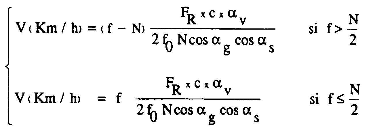
- FR,
- fréquence de récurrence du radar
- c,
- la vitesse de la lumière
et - αv,
- le facteur de conversion de m/s en km/h égal à 3,6.
- F R ,
- radar recurrence frequency
- vs,
- the speed of light
and - α v ,
- the conversion factor from m / s to km / h equal to 3.6.
Doté de seconds moyens de calcul 32, le système selon
l'invention peut également extraire la longueur Lv d'un véhicule détecté.
La figure 6 montre qu'il est nécessaire de faire une correction sur la
longueur mesurée par le radar 1. En effet, le diagramme 6 du radar 1
détecte l'avant du véhicule A lorsque ce dernier intercepte le début de la
case-distance 7, et la détection est réalisée jusqu'à ce que le véhicule
sorte totalement de cette case-distance. Si Lcd est la longueur de la case-distance
7, il faut tenir compte de l'erreur qu'elle provoque. Ainsi les
seconds moyens 32 de calcul de la longueur Lv d'un véhicule détecté
calculent cette longueur à partir de la vitesse V calculée par les premiers
moyens 31 en appliquant la relation :
A partir du nombre de véhicules détectés, de leur vitesse et de leur longueur, le système peut faire un bon nombre de statistiques intéressantes :From the number of vehicles detected, their speed and their length, the system can do lots of statistics interesting:
Il peut par exemple, en fixant une longueur de véhicule seuil,
calculer la densité de poids lourds présents dans la zone pendant une
durée de mesure. Il peut également extraire, par des troisièmes moyens
33, la vitesse moyenne Vmoy et la vitesse harmonique Vharm globales du
trafic pendant une durée totale de mesure TTOT. Les troisièmes moyens
33 calculent pour cela les relations :
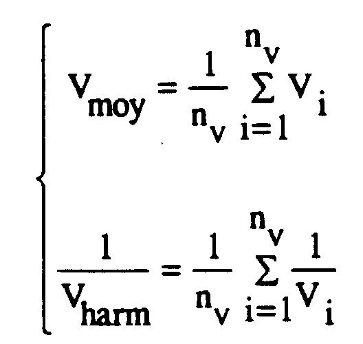
et Vi est la vitesse d'un véhicule détecté, fournie par les premiers
moyens 31.It can for example, by setting a threshold vehicle length, calculate the density of heavy goods vehicles present in the area during a measurement period. It can also be extracted, by
and V i is the speed of a detected vehicle, supplied by the
Le système de l'invention tel qu'il vient d'être décrit présente de nombreux avantages par rapport aux systèmes connus :The system of the invention as just described presents many advantages compared to known systems:
Il permet de contrôler, avec un radar unique, et sans balayage de faisceau, une pluralité de voies de circulation en même temps, et ceci, quel que soit le sens de circulation.It allows to control, with a single radar, and without scanning beam, a plurality of traffic lanes at the same time, and this, whatever the direction of traffic.
Les modules de traitement de signal 2 et d'extraction de
paramètres 3 sont avantageusement réalisés sous forme de programmes
informatiques. Les calculs peuvent être faits en temps réel, ou en temps
différé si l'on dote le système de moyens de mémorisation 24.The signal processing 2 and
La mise en place, par exemple sur mât, le réglage et l'entretien du système sont aisés, et l'encombrement modéré.Installation, for example on a mast, adjustment and maintenance of the system are easy, and the congestion moderate.
En outre, les performances du système de l'invention sont indépendantes des conditions climatiques. On peut envisager également d'implanter plusieurs systèmes sur différents points d'une route ou autoroute, et de corréler les résultats issus de chaque système grâce à une station de recueil des informations, de manière à avoir un suivi de l'évolution du trafic.In addition, the performance of the system of the invention is independent of climatic conditions. We can also consider to install several systems on different points of a road or highway, and correlate the results from each system with an information collection station, so as to have a follow-up of traffic development.
Enfin, le système peut être positionné en des points névralgiques d'un réseau autoroutier (bretelle d'entrée ou de sortie, abord d'un péage, entrée ou sortie d'une aire de repos...).Finally, the system can be positioned at points nerve centers of a motorway network (entry or exit ramp, approaching a toll, entering or leaving a rest area ...).
Claims (9)
- System for travelling calculating at least one parameter for checking vehicular traffic travelling on at least two traffic lanes including a radar (1), a module for processing the reception signal from the radar (2) provided with a sampler/coder (20), with Fourier transform calculation means (21) and with detection means (23), and a module (3) for extracting the said parameter operating on the basis of the output signals of the detection means (23) and the Fourier transform calculation means (21), characterized in that the said radar (1) is a pulse radar with a transmitter (11) transmitting pulses of given carrier frequency f0 and of duration τ, with a receiver (15) operating outside the pulse transmission periods and with a radiation diagram which is narrow in terms of bearing, sufficiently wide in terms of elevation as to cover the said lanes and allow simultaneous checking of the said lanes, and inclined by an angle of elevation αs and by an angle of bearing αg, the values of the pulse duration τ, of the angle of elevation αs and of the angle of bearing αg being chosen such that at least one range bin of the radar is included within a lane, and in that the said Fourier transform calculation means operate on an integer Number N of time samples output by the sampler/coder for each range bin corresponding to each traffic lane and that the said module for processing the reception signal from the radar (2) is provided with a filter (22) for smoothing the amplitude of the frequency samples output by the calculation means and which is interposed between the Fourier transform calculation means (21) and the detection means (23) which are means for comparing the amplitude of the samples output by the smoothing filter with a given threshold so as to detect the passage of a vehicle over each lane.
- Calculation system according to Claim 1, characterized in that the radiation diagram (6) has an elevation gain G () that is a function of the elevation angle and varies with the square of the cosecant according to the following relation:G0 = the practically constant gain of the radiation diagram for elevation angles less than 00 and max are two predetermined elevation angles.
- Calculation system according to any one of the preceding claims, characterized in that the said parameter is the number n of vehicles travelling in each lane, and in that the extraction module (3) contains incrementation means (30) increasing by one unit each time that a vehicle is detected.
- Calculation system according to any one of Claims 1 to 3, characterized in that the said parameter is the speed V of a vehicle detected within a speed range Dv, and in that the extraction module (3) contains first means (31) for calculating this speed searching for the order f of the non-zero frequency sample corresponding to the maximum amplitude of the samples output by the filter (22), and calculating the vehicle speed V by application of the following relations:FR = radar recurrence frequencyc = the speed of light =
andαv is the conversion factor from m/s to km/h, equal to 3.6. - Calculation system according to Claim 4, characterized in that it also calculates the length Lv of a detected vehicle, and in that the extraction module (3) contains second means (32) for calculating this length by application of the following relation:
- Calculation system according to any one of Claims 4 or 5, characterized in that it also calculates the average speed Vave and the harmonic speed Vharm of all vehicles detected during a total measurement period TTOT, and characterized in that the extraction module (3) contains third means (33) for calculating these speeds by application of the following relations:
 where
where nv = the number of vehicles detected during the total periodVi = the speed of a detected vehicle.
 - Calculation system according to any one of the preceding claims, characterized in that the smoothing filter (22) is a low-pass type filter replacing the amplitude of each sample output by the means (21) for calculating the Fourier transform, by the average of the said amplitude with those of an even number of samples taken on either side of the said sample.
- Calculation system according to any one of the preceding claims, characterized in that the processing module (2) and extraction module (3) run off-line by virtue of storage means (24).
- Calculation system according to any one of the preceding claims, characterized in that the height h is greater than the maximum possible height of a vehicle.
Applications Claiming Priority (2)
| Application Number | Priority Date | Filing Date | Title |
|---|---|---|---|
| FR9210965A FR2695742B1 (en) | 1992-09-15 | 1992-09-15 | System for calculating at least one vehicle traffic control parameter. |
| FR9210965 | 1992-09-15 |
Publications (2)
| Publication Number | Publication Date |
|---|---|
| EP0588687A1 EP0588687A1 (en) | 1994-03-23 |
| EP0588687B1 true EP0588687B1 (en) | 1998-03-04 |
Family
ID=9433502
Family Applications (1)
| Application Number | Title | Priority Date | Filing Date |
|---|---|---|---|
| EP93402175A Expired - Lifetime EP0588687B1 (en) | 1992-09-15 | 1993-09-07 | System for determining at least one control parameter for vehicular traffic |
Country Status (6)
| Country | Link |
|---|---|
| US (1) | US5402346A (en) |
| EP (1) | EP0588687B1 (en) |
| JP (1) | JPH06194443A (en) |
| CA (1) | CA2106115A1 (en) |
| DE (1) | DE69317186T2 (en) |
| FR (1) | FR2695742B1 (en) |
Families Citing this family (54)
| Publication number | Priority date | Publication date | Assignee | Title |
|---|---|---|---|---|
| JP3110095B2 (en) * | 1991-09-20 | 2000-11-20 | 富士通株式会社 | Distance measuring method and distance measuring device |
| US5586063A (en) * | 1993-09-01 | 1996-12-17 | Hardin; Larry C. | Optical range and speed detection system |
| FR2718874B1 (en) * | 1994-04-15 | 1996-05-15 | Thomson Csf | Traffic monitoring method for automatic detection of vehicle incidents. |
| GB2329293B (en) * | 1994-10-03 | 1999-04-28 | Seiko Precision Kk | Distance measuring apparatus |
| JPH08105742A (en) * | 1994-10-03 | 1996-04-23 | Seikosha Co Ltd | Distance measuring apparatus |
| US5570093A (en) * | 1995-02-10 | 1996-10-29 | Applied Concepts, Inc. | Police traffic radar using absolute signal strength information to improve target signal processing accuracy |
| US5663720A (en) * | 1995-06-02 | 1997-09-02 | Weissman; Isaac | Method and system for regional traffic monitoring |
| ES2195127T3 (en) * | 1996-04-01 | 2003-12-01 | Gatsometer Bv | METHOD AND APPLIANCE TO DETERMINE THE SPEED AND SITUATION OF A VEHICLE. |
| US6011515A (en) * | 1996-10-08 | 2000-01-04 | The Johns Hopkins University | System for measuring average speed and traffic volume on a roadway |
| US6531982B1 (en) | 1997-09-30 | 2003-03-11 | Sirf Technology, Inc. | Field unit for use in a GPS system |
| US6327471B1 (en) | 1998-02-19 | 2001-12-04 | Conexant Systems, Inc. | Method and an apparatus for positioning system assisted cellular radiotelephone handoff and dropoff |
| US6348744B1 (en) | 1998-04-14 | 2002-02-19 | Conexant Systems, Inc. | Integrated power management module |
| EP1099203B1 (en) * | 1998-07-17 | 2003-09-17 | Siemens Aktiengesellschaft | Method for detecting a vehicle traffic status and system for detecting said traffic status |
| US7711038B1 (en) | 1998-09-01 | 2010-05-04 | Sirf Technology, Inc. | System and method for despreading in a spread spectrum matched filter |
| US7545854B1 (en) * | 1998-09-01 | 2009-06-09 | Sirf Technology, Inc. | Doppler corrected spread spectrum matched filter |
| US6693953B2 (en) | 1998-09-30 | 2004-02-17 | Skyworks Solutions, Inc. | Adaptive wireless communication receiver |
| US6606349B1 (en) | 1999-02-04 | 2003-08-12 | Sirf Technology, Inc. | Spread spectrum receiver performance improvement |
| US6448925B1 (en) | 1999-02-04 | 2002-09-10 | Conexant Systems, Inc. | Jamming detection and blanking for GPS receivers |
| US6304216B1 (en) | 1999-03-30 | 2001-10-16 | Conexant Systems, Inc. | Signal detector employing correlation analysis of non-uniform and disjoint sample segments |
| US6577271B1 (en) | 1999-03-30 | 2003-06-10 | Sirf Technology, Inc | Signal detector employing coherent integration |
| US6351486B1 (en) | 1999-05-25 | 2002-02-26 | Conexant Systems, Inc. | Accelerated selection of a base station in a wireless communication system |
| US6931055B1 (en) | 2000-04-18 | 2005-08-16 | Sirf Technology, Inc. | Signal detector employing a doppler phase correction system |
| US6788655B1 (en) | 2000-04-18 | 2004-09-07 | Sirf Technology, Inc. | Personal communications device with ratio counter |
| US6952440B1 (en) | 2000-04-18 | 2005-10-04 | Sirf Technology, Inc. | Signal detector employing a Doppler phase correction system |
| US6714158B1 (en) * | 2000-04-18 | 2004-03-30 | Sirf Technology, Inc. | Method and system for data detection in a global positioning system satellite receiver |
| US7885314B1 (en) | 2000-05-02 | 2011-02-08 | Kenneth Scott Walley | Cancellation system and method for a wireless positioning system |
| US6778136B2 (en) * | 2001-12-13 | 2004-08-17 | Sirf Technology, Inc. | Fast acquisition of GPS signal |
| AUPR631801A0 (en) * | 2001-07-12 | 2001-08-02 | Luscombe, Andrew | Roadside sensor system |
| US6693557B2 (en) | 2001-09-27 | 2004-02-17 | Wavetronix Llc | Vehicular traffic sensor |
| US6943727B2 (en) * | 2002-10-29 | 2005-09-13 | Volkswagen Ag | Length measurement with radar |
| DE10260434A1 (en) * | 2002-12-21 | 2004-07-08 | Volkswagen Ag | Length measurement with radar |
| US7426450B2 (en) * | 2003-01-10 | 2008-09-16 | Wavetronix, Llc | Systems and methods for monitoring speed |
| US20050209762A1 (en) * | 2004-03-18 | 2005-09-22 | Ford Global Technologies, Llc | Method and apparatus for controlling a vehicle using an object detection system and brake-steer |
| US7558695B2 (en) * | 2004-08-10 | 2009-07-07 | Speedinfo, Llc | Self-powered vehicle speed sensor |
| US8370054B2 (en) * | 2005-03-24 | 2013-02-05 | Google Inc. | User location driven identification of service vehicles |
| US7558536B2 (en) * | 2005-07-18 | 2009-07-07 | EIS Electronic Integrated Systems, Inc. | Antenna/transceiver configuration in a traffic sensor |
| US7454287B2 (en) * | 2005-07-18 | 2008-11-18 | Image Sensing Systems, Inc. | Method and apparatus for providing automatic lane calibration in a traffic sensor |
| US7768427B2 (en) * | 2005-08-05 | 2010-08-03 | Image Sensign Systems, Inc. | Processor architecture for traffic sensor and method for obtaining and processing traffic data using same |
| US7474259B2 (en) * | 2005-09-13 | 2009-01-06 | Eis Electronic Integrated Systems Inc. | Traffic sensor and method for providing a stabilized signal |
| US8248272B2 (en) * | 2005-10-31 | 2012-08-21 | Wavetronix | Detecting targets in roadway intersections |
| US8665113B2 (en) | 2005-10-31 | 2014-03-04 | Wavetronix Llc | Detecting roadway targets across beams including filtering computed positions |
| US7541943B2 (en) * | 2006-05-05 | 2009-06-02 | Eis Electronic Integrated Systems Inc. | Traffic sensor incorporating a video camera and method of operating same |
| US7990313B2 (en) * | 2006-07-13 | 2011-08-02 | Siemens Aktiengesellschaft | Radar arrangement |
| DE102007022372A1 (en) | 2007-05-07 | 2008-11-13 | Robot Visual Systems Gmbh | Method and device for determining the vehicle class of vehicles |
| DE102007022373A1 (en) * | 2007-05-07 | 2008-11-13 | Robot Visual Systems Gmbh | Method for conclusively detecting the speed of a vehicle |
| TW201133412A (en) * | 2010-03-19 | 2011-10-01 | Cct Co Ltd | Method of using radar vehicle detector to determine vehicle type, speed, and radar detection zone width |
| DE102010024152B4 (en) * | 2010-06-17 | 2014-09-18 | Rtb Gmbh & Co. Kg | Arrangement for measuring the height of a vehicle |
| US9507014B2 (en) * | 2011-06-21 | 2016-11-29 | Kapsch Trafficcom Ag | Method and device for detecting a rotating wheel |
| US9412271B2 (en) | 2013-01-30 | 2016-08-09 | Wavetronix Llc | Traffic flow through an intersection by reducing platoon interference |
| DE102013002994B4 (en) * | 2013-02-22 | 2017-04-27 | S.M.S Smart Microwave Sensors Gmbh | Method and device for determining a coverage area of a traffic route |
| DK2804014T3 (en) * | 2013-05-13 | 2015-08-10 | Kapsch Trafficcom Ag | DEVICES AND METHOD FOR ESTABLISHING A characteristic feature of A VEHICLE |
| HUE026013T2 (en) * | 2013-05-13 | 2016-05-30 | Kapsch Trafficcom Ag | Device for measuring the position of a vehicle or a surface thereof |
| JP2015087120A (en) * | 2013-10-28 | 2015-05-07 | 住友電気工業株式会社 | Radio wave sensor and detection method |
| FR3050279B1 (en) | 2016-04-19 | 2018-05-11 | Thales | AUTOMATIC CALCULATION OF A DIMENSION OF A MOBILE PLATFORM |
Family Cites Families (9)
| Publication number | Priority date | Publication date | Assignee | Title |
|---|---|---|---|---|
| US3408648A (en) * | 1966-12-02 | 1968-10-29 | Lab For Electronics Inc | Speed sensor |
| GB1315533A (en) * | 1970-06-24 | 1973-05-02 | Pye Ltd | Vehicle monitoring radar apparatus |
| US3876946A (en) * | 1973-10-31 | 1975-04-08 | Singer Co | Radio frequency digital fourier analyzer |
| US4317117A (en) * | 1979-07-20 | 1982-02-23 | Chasek Norman E | Cross correlated doppler radar/infra red velocity and presence sensor |
| FR2517069A1 (en) * | 1981-11-24 | 1983-05-27 | Lmt Radio Professionelle | LAND SURVEILLANCE DOPPLER RADAR |
| FR2622021B1 (en) * | 1987-10-16 | 1990-05-04 | Trt Telecom Radio Electr | DEVICE FOR MEASURING THE DISTANCE "H" WHICH SEPARATES IT FROM AN OBJECT |
| DE3810357A1 (en) * | 1988-03-26 | 1989-10-05 | Licentia Gmbh | METHOD FOR LOCAL TRAFFIC DATA ACQUISITION AND EVALUATION AND DEVICE FOR CARRYING OUT THE METHOD |
| JP2712844B2 (en) * | 1990-04-27 | 1998-02-16 | 株式会社日立製作所 | Traffic flow measurement device and traffic flow measurement control device |
| US5161107A (en) * | 1990-10-25 | 1992-11-03 | Mestech Creation Corporation | Traffic surveillance system |
-
1992
- 1992-09-15 FR FR9210965A patent/FR2695742B1/en not_active Expired - Fee Related
-
1993
- 1993-08-25 US US08/112,842 patent/US5402346A/en not_active Expired - Fee Related
- 1993-08-30 JP JP5214238A patent/JPH06194443A/en active Pending
- 1993-09-07 EP EP93402175A patent/EP0588687B1/en not_active Expired - Lifetime
- 1993-09-07 DE DE69317186T patent/DE69317186T2/en not_active Expired - Fee Related
- 1993-09-14 CA CA002106115A patent/CA2106115A1/en not_active Abandoned
Also Published As
| Publication number | Publication date |
|---|---|
| JPH06194443A (en) | 1994-07-15 |
| DE69317186D1 (en) | 1998-04-09 |
| FR2695742B1 (en) | 1994-10-21 |
| FR2695742A1 (en) | 1994-03-18 |
| US5402346A (en) | 1995-03-28 |
| DE69317186T2 (en) | 1998-06-25 |
| EP0588687A1 (en) | 1994-03-23 |
| CA2106115A1 (en) | 1994-03-16 |
Similar Documents
| Publication | Publication Date | Title |
|---|---|---|
| EP0588687B1 (en) | System for determining at least one control parameter for vehicular traffic | |
| FR2718874A1 (en) | Traffic monitoring method for automatic vehicle incident detection. | |
| EP0568427B1 (en) | Method and system for detecting one or more objects in an angular sector, with applications | |
| EP3282283A1 (en) | Fmcw radar detection method with multiple resolution and radar using such a method | |
| WO1993021540A1 (en) | Method and system for determining the position and direction of a moving object and applications thereof | |
| EP0658775B1 (en) | Anticollision device for automotive vehicle | |
| EP0389325B1 (en) | Method and apparatus for assisting land vehicle traffic | |
| EP2096611A1 (en) | Device and method for multi-technology detection of a vehicle | |
| FR2905765A1 (en) | DEVICE AND METHOD FOR ESTIMATING THE DIMENSIONS OF A PARKING PLACE, MOTOR VEHICLE COMPRISING SUCH A DEVICE. | |
| EP3074786A1 (en) | Anticollision radar, especially for an aircraft when taxiing, and anticollision system | |
| EP3945345A1 (en) | Method for controlling a vehicle by a plurality of sensors | |
| FR2752983A1 (en) | VEHICLE POSITION MEASUREMENT SYSTEM | |
| FR2880133A1 (en) | RADAR SYSTEM FOR MONITORING TARGETS IN DIFFERENT BEACHES OF DISTANCE | |
| FR2618543A1 (en) | Device for analysing the surface condition of the ground for a moving object which can come into contact with this ground | |
| EP2948790B1 (en) | Driver assistance system | |
| WO2020188158A1 (en) | Cooperative communications device for transport systems combining on-board radars and v2v inter-vehicle communications | |
| FR2941077A1 (en) | IDENTIFICATION SYSTEM FOR COLLECTING DATA FROM AT LEAST ONE VEHICLE | |
| FR2675610A1 (en) | METHOD AND INSTALLATION FOR EVALUATING A TRAFFIC FLOW OF ROAD VEHICLES. | |
| EP1012625A1 (en) | Anticollision method for vehicle | |
| FR2487985A1 (en) | DEVICE AND METHOD FOR ATTACKING ANTENNAS FOR A VERY HIGH FREQUENCY OMNIDIRECTIONAL NAVIGATION SYSTEM | |
| EP0058596B1 (en) | Selective transmission system for traffic information | |
| EP3712657B1 (en) | Improved viewing system for an aircraft, associated aircraft and viewing method | |
| FR2769978A1 (en) | VEHICLE SPEED LOCATION AND / OR MEASUREMENT METHOD, AND IMPLEMENTATION DEVICE | |
| FR2617315A1 (en) | Method and device for discerning the type of a motor vehicle while moving | |
| FR2887635A1 (en) | VEHICLE LOCATION DEVICE BY RADIO FREQUENCY TRANSMISSION |
Legal Events
| Date | Code | Title | Description |
|---|---|---|---|
| PUAI | Public reference made under article 153(3) epc to a published international application that has entered the european phase |
Free format text: ORIGINAL CODE: 0009012 |
|
| AK | Designated contracting states |
Kind code of ref document: A1 Designated state(s): DE FR GB IT SE |
|
| 17P | Request for examination filed |
Effective date: 19940901 |
|
| 17Q | First examination report despatched |
Effective date: 19960611 |
|
| GRAG | Despatch of communication of intention to grant |
Free format text: ORIGINAL CODE: EPIDOS AGRA |
|
| GRAG | Despatch of communication of intention to grant |
Free format text: ORIGINAL CODE: EPIDOS AGRA |
|
| GRAH | Despatch of communication of intention to grant a patent |
Free format text: ORIGINAL CODE: EPIDOS IGRA |
|
| GRAH | Despatch of communication of intention to grant a patent |
Free format text: ORIGINAL CODE: EPIDOS IGRA |
|
| GRAA | (expected) grant |
Free format text: ORIGINAL CODE: 0009210 |
|
| AK | Designated contracting states |
Kind code of ref document: B1 Designated state(s): DE FR GB IT SE |
|
| ITF | It: translation for a ep patent filed |
Owner name: JACOBACCI & PERANI S.P.A. |
|
| REF | Corresponds to: |
Ref document number: 69317186 Country of ref document: DE Date of ref document: 19980409 |
|
| GBT | Gb: translation of ep patent filed (gb section 77(6)(a)/1977) |
Effective date: 19980507 |
|
| PLBE | No opposition filed within time limit |
Free format text: ORIGINAL CODE: 0009261 |
|
| STAA | Information on the status of an ep patent application or granted ep patent |
Free format text: STATUS: NO OPPOSITION FILED WITHIN TIME LIMIT |
|
| 26N | No opposition filed | ||
| PGFP | Annual fee paid to national office [announced via postgrant information from national office to epo] |
Ref country code: SE Payment date: 20000815 Year of fee payment: 8 |
|
| PGFP | Annual fee paid to national office [announced via postgrant information from national office to epo] |
Ref country code: DE Payment date: 20010821 Year of fee payment: 9 |
|
| PGFP | Annual fee paid to national office [announced via postgrant information from national office to epo] |
Ref country code: GB Payment date: 20010822 Year of fee payment: 9 |
|
| PG25 | Lapsed in a contracting state [announced via postgrant information from national office to epo] |
Ref country code: SE Free format text: LAPSE BECAUSE OF NON-PAYMENT OF DUE FEES Effective date: 20010908 |
|
| PGFP | Annual fee paid to national office [announced via postgrant information from national office to epo] |
Ref country code: FR Payment date: 20010925 Year of fee payment: 9 |
|
| REG | Reference to a national code |
Ref country code: GB Ref legal event code: IF02 |
|
| EUG | Se: european patent has lapsed |
Ref document number: 93402175.9 |
|
| PG25 | Lapsed in a contracting state [announced via postgrant information from national office to epo] |
Ref country code: GB Free format text: LAPSE BECAUSE OF NON-PAYMENT OF DUE FEES Effective date: 20020907 |
|
| REG | Reference to a national code |
Ref country code: FR Ref legal event code: CD |
|
| PG25 | Lapsed in a contracting state [announced via postgrant information from national office to epo] |
Ref country code: DE Free format text: LAPSE BECAUSE OF NON-PAYMENT OF DUE FEES Effective date: 20030401 |
|
| GBPC | Gb: european patent ceased through non-payment of renewal fee |
Effective date: 20020907 |
|
| PG25 | Lapsed in a contracting state [announced via postgrant information from national office to epo] |
Ref country code: FR Free format text: LAPSE BECAUSE OF NON-PAYMENT OF DUE FEES Effective date: 20030603 |
|
| REG | Reference to a national code |
Ref country code: FR Ref legal event code: ST |
|
| PG25 | Lapsed in a contracting state [announced via postgrant information from national office to epo] |
Ref country code: IT Free format text: LAPSE BECAUSE OF NON-PAYMENT OF DUE FEES Effective date: 20050907 |