EP0587702B1 - Disc-type coin sorter with multiple-path queuing - Google Patents
Disc-type coin sorter with multiple-path queuing Download PDFInfo
- Publication number
- EP0587702B1 EP0587702B1 EP92912074A EP92912074A EP0587702B1 EP 0587702 B1 EP0587702 B1 EP 0587702B1 EP 92912074 A EP92912074 A EP 92912074A EP 92912074 A EP92912074 A EP 92912074A EP 0587702 B1 EP0587702 B1 EP 0587702B1
- Authority
- EP
- European Patent Office
- Prior art keywords
- coins
- wall
- disc
- channel
- sorting head
- Prior art date
- Legal status (The legal status is an assumption and is not a legal conclusion. Google has not performed a legal analysis and makes no representation as to the accuracy of the status listed.)
- Expired - Lifetime
Links
Images


Classifications
-
- G—PHYSICS
- G07—CHECKING-DEVICES
- G07D—HANDLING OF COINS OR VALUABLE PAPERS, e.g. TESTING, SORTING BY DENOMINATIONS, COUNTING, DISPENSING, CHANGING OR DEPOSITING
- G07D9/00—Counting coins; Handling of coins not provided for in the other groups of this subclass
- G07D9/008—Feeding coins from bulk
-
- G—PHYSICS
- G07—CHECKING-DEVICES
- G07D—HANDLING OF COINS OR VALUABLE PAPERS, e.g. TESTING, SORTING BY DENOMINATIONS, COUNTING, DISPENSING, CHANGING OR DEPOSITING
- G07D3/00—Sorting a mixed bulk of coins into denominations
- G07D3/12—Sorting coins by means of stepped deflectors
- G07D3/128—Rotary devices
Definitions
- the present invention relates generally to coin sorting devices, and more particularly, to coin sorters of the type which use a resilient disc rotating beneath a stationary sorting head sorting coins of mixed denominations.
- US-A-4 731 043 discloses a coin sorter with a disc rotatable by a motor and a stationary sorting head having a lower surface parallel to an upper surface of the rotatable disc and spaced slightly therefrom.
- a channel or recess is formed in the lower surface of the sorting head for receiving coins passing beneath an inner edge of the sorting head and guiding those coins as they are carried along the lower surface of the sorting head by the rotating disc.
- the channel has an outer wall and an inner wall, whereby both walls comprise different sections.
- the outer wall comprises a section with a spiralling edge whereby this section is interrupted by a recessed area with an inner wall.
- This inner wall smoothly connects the spiralling edge.
- a circular edge is arranged at the end of spiralling edge.
- the inner wall also comprises a number of different sections.
- a tapered portion extends outwardly from a centre of rotation of the sorting head.
- an outward projection is arranged opposite to recessed area.
- an outer edge region has generally fixed radial configuration and in the fourth section a further outer edge region extends outwardly.
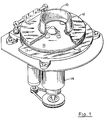
- a hopper 10 receives coins of mixed denominations and feeds them through a central feed aperture in an annular sorting head or guide plate 12. As the coins pass through the feed aperture, they are deposited on the top surface of a rotatable disc 13. This disc 13 is mounted for rotation on a stub shaft (not shown) and driven by an electric motor 14 attached to a mounting plate 15.
- the disc 13 comprises a resilient pad 16, preferably made of a resilient rubber or polymeric material, bonded to the top surface of a solid metal disc 17.
- the coins deposited on the top surface thereof tend to slide outwardly over the surface of the pad 16 due to centrifugal force.
- those coins which are lying flat on the pad 16 enter the gap between the pad surface and the sorting head 12 because the underside of the inner periphery of the sorting head is spaced above the pad 16 by a distance which is approximately as great as the thickness of the thickest coin.
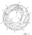
- the coins are sorted into their respective denominations, and the coins for each denomination issue from a respective exit slot, such as the slots 20, 21, 22, 23, 24 and 25.
- the particular embodiment illustrated in FIG. 2 was specifically designed for handling six Australian coins, i.e., all the Australian coins except the one-cent and two-cent coins.
- the outwardly moving coins initially enter the entry region 30 formed in the underside of the sorting head 12 and extending around a major portion of the inner periphery of the sorting head.
- the outer wall 31 of the entry region 30 extends downwardly to the lowermost surface 32 of the sorting head, which is preferably spaced from the top surface of the pad 16 by a distance, e.g., 0.254 mm (0.010 inch), which is slightly less than the thickness of the thinnest coins. Consequently, the initial radial movement of the coins is terminated when they engage the wall 31 of the region 30, though the coins continue to move circumferentially along the wall 31 by the rotational movement of the pad 16.
- the only portion of the central opening of the guide plate 12 which does not open directly into the recess 30 is that sector of the periphery which is occupied by a land 33 whose lower surface is at a slightly higher elevation than the lowermost surface 32 of the sorting head.
- the upstream end of the land 33 forms a ramp 33a (FIG. 2).
- a coin When only partially entered the entry region 30, it engages the ramp 33a on the leading edge of the land 33.
- the ramp 33a presses the coin downwardly into the resilient pad 16, which causes the coin to be recirculated.
- a recycling channel 50 is provided at the outlet of the channel 41 for recycling coins which do not have their outer edges close to the outer wall of the channel 41.
- the spiral channel 41 causes coins of different thicknesses and/or diameters to follow different paths which facilitate the queuing of the coins and increase the coin throughput rate. Though following different paths, the coins of all denominations exit the spiral channel 41 with a common edge (the outer edges of all coins) aligned at the same or approximately the same radial position so that the opposite (inner) edges of the coins can be used for sorting.
- the spiral channel 41 is deeper than the thinner coins, such as the 5-cent and 10-cent coins in the Australian coin set, but shallow enough to press the thicker coins into the resilient pad 16.
- a deeper channel would not provide the desired queuing of coins within the spiral channel, such as the stripping action to be described below, and would allow the thin coins to bounce around within the channel.
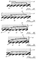
- Coins of different thicknesses and/or diameters follow different paths within the spiral channel 30, and these different paths have been separately illustrated in FIGS. 3-8, 9-14, 15-20, 21-26 and 27-32.
- FIGS. 3-8 illustrate the path followed by small, thin coins in a single layer.
- These are coins having a diameter smaller than the width of the channel between the inner wall 42 and the outer wall 43 at the exit end of the channel, and thin enough to avoid being pressed into the resilient pad.
- These coins are normally already against the wall 31 when they enter the spiral channel 41, and are guided through the entire length of the channel by the outer wall 43, exiting with their outer edges at the desired gaging radius R g .
- the illustrative spiral channel 41 strips apart stacked or shingled coins, as illustrated in FIGS. 9-14.
- the combined thickness of a pair of stacked or shingled coin is great enough to cause the lower coin in that pair to be pressed into the resilient pad. Consequently, that pair of coins will be rotated concentrically with the disc, as illustrated by the coin pairs C10 and C11 in FIGS. 9-11.
- the inner wall 42 spirals outwardly, the upper coin will eventually engage the tapered inner wall 42, as illustrated in FIG. 11, and the lower coin, as also illustrated in FIG. 11, will pass under that wall 42 (see FIG. 12).
- the latter coin will be recirculated back to the entry region of the sorting head and will later re-enter the spiral channel.
- the preferred taper of the wall 42 is about 35°.
- the convergence of the inner and outer walls 42 and 43 is effected by progressively reducing the radius of the outer wall 43 near the outlet of the spiral channel 41, but it will be appreciated that an alternative would be to continue increasing the radius of the inner wall 42 while maintaining the radius of the outer wall 43 constant after it reaches its maximum radius.
- the inner and outer walls 42 and 43 must converge enough to bring the outer edges of the small-diameter, thick coins into engagement with the outer wall 43 so as to position the outer edges of such coins at the desired gaging radius R g .
- the minimum distance between the inner and outer walls 42 and 43, i.e., at the location of coin C20 in FIG. 20, is about the same as the diameter of the smallest coin that is thick enough to be pressed into the resilient pad in the channel region between the inner and middle walls. Consequently, when such a coin reaches the point where that distance is a minimum, the outer edge of the coin is adjacent the outer wall 43, as shown in FIGS. 19 and 20. Thus the small, thick coins exit the channel 41 with the outer edges of the coins at the gaging radius R g .
- Thick coins which have a diameter greater that the minimum distance between the inner and outer walls 42 and 43 follow the path shown in FIGS. 27-32. Because these coins are pressed into the resilient pad, they are rotated concentrically with the disc until the inner edges of the coins engage the inner wall 42 (see FIG. 28). These coins are then guided by the inner wall 42 until the outer edges of the coins engage the outer wall 43 (coin C30a). At that point the inner portions of such coins pass beneath the inner wall 42 and ride along the relieved region 44 (coin C30).
- the sorting head 12 forms the series of exit channels 20, 21, 22, 23, 24 and 25 which function as selecting means to discharge coins of different denominations at different circumferential locations around the periphery of the sorting head.
- the channels 20-25 are spaced circumferentially around the outer periphery of the sorting head 12, with the innermost edges of successive channels located progressively farther away from the common radial location of the outer edges of all coins for receiving and ejecting coins in order of increasing diameter.
- the six channels 20-25 are positioned and dimensioned to eject successively the 5-cent Australian coin (channel 20), the 2-dollar Australian coin (channel 21), the 10-cent Australian (channel 22), the 1-dollar Australian coin (channel 23), the 20-cent Australian coin (channel 24) and the 50-cent Australian coin (channel 25).
- the innermost edges of the exit channels 20-25 are positioned so that the inner edge of a coin of only one particular denomination can enter each channel; the coins of all other denominations reaching a given exit channel extend inwardly beyond the innermost edge of that particular channel so that those coins cannot enter the channel and, therefore, continue on to the next exit channel.
- the first exit channel 20 is intended to discharge only the 5-cent Australian coin, and thus the innermost edges 20a of this channel is located at a radius that is spaced inwardly from the radius of the gaging wall 61 by a distance that is only slightly greater than the diameter of that coin. Consequently, only the 5-cent coins can enter the channel 20. Because the outer edges of all denominations of coins are located at the same radial position when they leave the gaging channel 60, the inner edges of all denominations other than the 5-cent coins extend inwardly beyond the innermost edge 20a of the channel 20, thereby preventing those coins from entering that particular channel.
- the inner edges of only the 2-dollar Australian coins are located close enough to the periphery of the sorting head 12 to enter that exit channel.
- the inner edges of all other denominations extend inwardly beyond the innermost edge 21a of the channel 21 so that they remain gripped between the sorting head and the resilient pad. Consequently, such coins are rotated past the channel 21 and continue on to the next exit channel.
Landscapes
- Physics & Mathematics (AREA)
- General Physics & Mathematics (AREA)
- Testing Of Coins (AREA)
- Slot Machines And Peripheral Devices (AREA)
- Combined Means For Separation Of Solids (AREA)
Abstract
Description
- The present invention relates generally to coin sorting devices, and more particularly, to coin sorters of the type which use a resilient disc rotating beneath a stationary sorting head sorting coins of mixed denominations.
- US-A-4 731 043 discloses a coin sorter with a disc rotatable by a motor and a stationary sorting head having a lower surface parallel to an upper surface of the rotatable disc and spaced slightly therefrom. A channel or recess is formed in the lower surface of the sorting head for receiving coins passing beneath an inner edge of the sorting head and guiding those coins as they are carried along the lower surface of the sorting head by the rotating disc. The channel has an outer wall and an inner wall, whereby both walls comprise different sections.
- The outer wall comprises a section with a spiralling edge whereby this section is interrupted by a recessed area with an inner wall. This inner wall smoothly connects the spiralling edge. At the end of spiralling edge a circular edge is arranged.
- The inner wall also comprises a number of different sections. In a first section a tapered portion extends outwardly from a centre of rotation of the sorting head. In the second section an outward projection is arranged opposite to recessed area. In a third section an outer edge region has generally fixed radial configuration and in the fourth section a further outer edge region extends outwardly.
- By the different sections of the inner wall different passages of the channel are formed through which coins of different denominations can pass more or less easily, whereby said recessed area is used for inserting coins of greater diameter to circumvent said outward projection of the inner wall.
- With respect to US-A-4 731 043 it is an object of the present invention to provide an improved coin sorter which is capable of processing a wide variety of different coin sizes, i.e. the coin sets of different countries, without any significant changes in accuracy or throughput rate.
- In accordance with the present invention, the foregoing object is realised by the coin sorters as outlined in
claims 1 or 5. - Advantageous embodiments of the coin sorters are disclosed by the subclaims.
- Other objects and advantages of the invention will be apparent from the following detailed description and the accompanying drawings.
-
- FIG. 1 is perspective view of a coin sorter embodying the present invention, with portions thereof broken away to show the internal structure;
- FIG. 2 is an enlarged bottom plan view of the sorting head or guide plate in the coin sorter of FIG. 1;
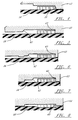
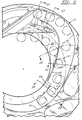
- FIG. 3 is an enlarged view of the right-hand portion of FIG. 2, with various coins superimposed thereon;
- FIG. 4 is an enlarged section taken generally along line 4-4 in FIG. 3, showing the coins in full elevation;
- FIG. 5 is an enlarged section taken generally along line 5-5 in FIG. 3, showing the coins in full elevation;
- FIG. 6 is an enlarged section taken generally along line 6-6 in FIG. 3, showing the coins in full elevation;
- FIG. 7 is an enlarged section taken generally along line 7-7 in FIG. 3, showing the coins in full elevation;
- FIG. 8 is an enlarged section taken generally along line 8-8 in FIG. 3, showing the coins in full elevation;
- FIG. 9 is an enlarged view of the right-hand portion of FIG. 2, with various coins superimposed thereon;
- FIG. 10 is an enlarged section taken generally along line 10-10 in FIG. 9, showing the coins in full elevation;
- FIG. 11 is an enlarged section taken generally along line 11-11 in FIG. 9, showing the coins in full elevation;
- FIG. 12 is an enlarged section taken generally along line 12-12 in FIG. 9, showing the coins in full elevation;
- FIG. 13 is an enlarged section taken generally along line 13-13 in FIG. 9, showing the coins in full elevation;
- FIG. 14 is an enlarged section taken generally along line 14-14 in FIG. 9, showing the coins in full elevation;
- FIG. 15 is an enlarged view of the right-hand portion of FIG. 2, with various coins superimposed thereon;
- FIG. 16 is an enlarged section taken generally along line 16-16 in FIG. 15, showing the coins in full elevation;
- FIG. 17 is an enlarged section taken generally along line 17-17 in FIG. 15, showing the coins in full elevation;
- FIG. 18 is an enlarged section taken generally along line 18-18 in FIG. 15, showing the coins in full elevation;
- FIG. 19 is an enlarged section taken generally along line 19-19 in FIG. 15, showing the coins in full elevation;
- FIG. 20 is an enlarged section taken generally along line 20-20 in FIG. 15, showing the coins in full elevation;
- FIG. 21 is an enlarged view of the right-hand portion of FIG. 2, with various coins superimposed thereon;
- FIG. 22 is an enlarged section taken generally along line 22-22 in FIG. 21, showing the coins in full elevation;
- FIG. 23 is an enlarged section taken generally along line 23-23 in FIG. 21, showing the coins in full elevation;
- FIG. 24 is an enlarged section taken generally along line 24-24 in FIG. 21, showing the coins in full elevation;
- FIG. 25 is an enlarged section taken generally along line 25-25 in FIG. 21, showing the coins in full elevation;
- FIG. 26 is an enlarged section taken generally along line 26-26 in FIG. 21, showing the coins in full elevation;
- FIG. 27 is an enlarged view of the right-hand portion of FIG. 2, with various coins superimposed thereon;
- FIG. 28 is an enlarged section taken generally along line 28-28 in FIG. 27, showing the coins in full elevation;
- FIG. 29 is an enlarged section taken generally along line 29-29 in FIG. 27, showing the coins in full elevation;
- FIG. 30 is an enlarged section taken generally along line 30-30 in FIG. 27, showing the coins in full elevation;
- FIG. 31 is an enlarged section taken generally along line 31-31 in FIG. 27, showing the coins in full elevation; and
- FIG. 32 is an enlarged section taken generally along line 32-32 in FIG. 27, showing the coins in full elevation.
- While the invention is susceptible to various modifications and alternative forms, a specific embodiment thereof has been shown by way of example in the drawings and will be described in detail. It should be understood, however, that it is not intended to limit the invention to the particular form described, but, on the contrary, the intention is to cover all modifications, equivalents, and alternatives falling within the spirit and scope of the invention as defined by the appended claims.
- Turning now to the drawings and referring first to FIG. 1, a
hopper 10 receives coins of mixed denominations and feeds them through a central feed aperture in an annular sorting head orguide plate 12. As the coins pass through the feed aperture, they are deposited on the top surface of arotatable disc 13. Thisdisc 13 is mounted for rotation on a stub shaft (not shown) and driven by anelectric motor 14 attached to a mounting plate 15. Thedisc 13 comprises aresilient pad 16, preferably made of a resilient rubber or polymeric material, bonded to the top surface of asolid metal disc 17. - As the
disc 13 is rotated, the coins deposited on the top surface thereof tend to slide outwardly over the surface of thepad 16 due to centrifugal force. As the coins move outwardly, those coins which are lying flat on thepad 16 enter the gap between the pad surface and thesorting head 12 because the underside of the inner periphery of the sorting head is spaced above thepad 16 by a distance which is approximately as great as the thickness of the thickest coin. As further described below, the coins are sorted into their respective denominations, and the coins for each denomination issue from a respective exit slot, such as theslots - As can be seen most clearly in FIG. 2, the outwardly moving coins initially enter the
entry region 30 formed in the underside of thesorting head 12 and extending around a major portion of the inner periphery of the sorting head. Theouter wall 31 of theentry region 30 extends downwardly to thelowermost surface 32 of the sorting head, which is preferably spaced from the top surface of thepad 16 by a distance, e.g., 0.254 mm (0.010 inch), which is slightly less than the thickness of the thinnest coins. Consequently, the initial radial movement of the coins is terminated when they engage thewall 31 of theregion 30, though the coins continue to move circumferentially along thewall 31 by the rotational movement of thepad 16. - As the
disc 13 rotates, thick coins in therecess 30 that are next to thewall 31 engage aramp 31a which presses the coins into thepad 16; thereafter their radial position is fixed by pressure between thepad 16 and asurface 31b. Thick coins which fail to initially engage theramp 31a, engage a wall along the inner edge of theramp 31a and thesurface 31b and are recirculated back into the feed opening of the sorting head. This prevents misaligned thick coins from hindering the flow of coins to thespiral channel 41. - The only portion of the central opening of the
guide plate 12 which does not open directly into therecess 30 is that sector of the periphery which is occupied by aland 33 whose lower surface is at a slightly higher elevation than thelowermost surface 32 of the sorting head. The upstream end of theland 33 forms aramp 33a (FIG. 2). When a coin has only partially entered theentry region 30, it engages theramp 33a on the leading edge of theland 33. Theramp 33a presses the coin downwardly into theresilient pad 16, which causes the coin to be recirculated. - Coins which clear the
ramp 33a enter thespiral channel 41 which guides the coins to thegaging channel 60. Arecycling channel 50 is provided at the outlet of thechannel 41 for recycling coins which do not have their outer edges close to the outer wall of thechannel 41. - The
spiral channel 41 causes coins of different thicknesses and/or diameters to follow different paths which facilitate the queuing of the coins and increase the coin throughput rate. Though following different paths, the coins of all denominations exit thespiral channel 41 with a common edge (the outer edges of all coins) aligned at the same or approximately the same radial position so that the opposite (inner) edges of the coins can be used for sorting. - The
spiral channel 41 is deeper than the thinner coins, such as the 5-cent and 10-cent coins in the Australian coin set, but shallow enough to press the thicker coins into theresilient pad 16. A deeper channel would not provide the desired queuing of coins within the spiral channel, such as the stripping action to be described below, and would allow the thin coins to bounce around within the channel. Coins of different thicknesses and/or diameters follow different paths within thespiral channel 30, and these different paths have been separately illustrated in FIGS. 3-8, 9-14, 15-20, 21-26 and 27-32. - Referring first to FIGS. 3-8, these figures illustrate the path followed by small, thin coins in a single layer. These are coins having a diameter smaller than the width of the channel between the
inner wall 42 and theouter wall 43 at the exit end of the channel, and thin enough to avoid being pressed into the resilient pad. These coins are normally already against thewall 31 when they enter thespiral channel 41, and are guided through the entire length of the channel by theouter wall 43, exiting with their outer edges at the desired gaging radius Rg. - The
illustrative spiral channel 41 strips apart stacked or shingled coins, as illustrated in FIGS. 9-14. In general, the combined thickness of a pair of stacked or shingled coin is great enough to cause the lower coin in that pair to be pressed into the resilient pad. Consequently, that pair of coins will be rotated concentrically with the disc, as illustrated by the coin pairs C10 and C11 in FIGS. 9-11. Because theinner wall 42 spirals outwardly, the upper coin will eventually engage the taperedinner wall 42, as illustrated in FIG. 11, and the lower coin, as also illustrated in FIG. 11, will pass under that wall 42 (see FIG. 12). As shown in FIG. 9, the latter coin will be recirculated back to the entry region of the sorting head and will later re-enter the spiral channel. The preferred taper of thewall 42 is about 35°. - Small, thick coins follow the path illustrated in FIGS. 15-20. The thickness of these coins is greater than the distance between the channel ceiling and the resilient pad, as a result of which the coins are pressed into the resilient pad (see FIG. 16). Consequently, these coins are not free to follow the
outer wall 43 as it spirals outwardly, but rather move concentrically with the disc until they engage the inner wall 42 (see FIGS. 16 and 17). They are then guided by theinner wall 42 which guides the coins outwardly until their outer edges engage theouter wall 43 as it converges with theinner wall 42. In the illustrative embodiment, the convergence of the inner andouter walls outer wall 43 near the outlet of thespiral channel 41, but it will be appreciated that an alternative would be to continue increasing the radius of theinner wall 42 while maintaining the radius of theouter wall 43 constant after it reaches its maximum radius. Whichever technique is used, the inner andouter walls outer wall 43 so as to position the outer edges of such coins at the desired gaging radius Rg. - The minimum distance between the inner and
outer walls outer wall 43, as shown in FIGS. 19 and 20. Thus the small, thick coins exit thechannel 41 with the outer edges of the coins at the gaging radius Rg. - Larger-diameter thin coins follow the
outer wall 43 of thespiral channel 41, as illustrated in FIGS. 21-26, in the same manner as the small-diameter thin coins. At the outlet end of thespiral channel 41, however, the radial distance between the inner andouter walls spiral channel 41 with their outer edges at the desired gaging radius Rg, theregion 44 inboard of theinner wall 42 is relieved so that the inner portions of such coins can pass under thewall 42. The outer edges of those coins then continue to follow theouter wall 43. - Thick coins which have a diameter greater that the minimum distance between the inner and
outer walls inner wall 42 until the outer edges of the coins engage the outer wall 43 (coin C30a). At that point the inner portions of such coins pass beneath theinner wall 42 and ride along the relieved region 44 (coin C30). - It can occur that correctly aligned coins passing under the
recycling channel 50 can be slightly shifted in their radial position. To correct this, coins which pass therecycling channel 50 enter thegaging channel 60 which allows the coins to be realigned against the radiallyouter wall 61. Thechannel 60 andwall 61 allow the coins in the sorting path an opportunity to realign their outer edges at the radial position required for correct sorting. To ensure that every coin engages thewall 61, the radius of thewall 61 from the center of the disc is gradually decreased along the length of thechannel 60. - Beyond the
gaging channel 60, the sortinghead 12 forms the series ofexit channels head 12, with the innermost edges of successive channels located progressively farther away from the common radial location of the outer edges of all coins for receiving and ejecting coins in order of increasing diameter. In the particular embodiment illustrated, the six channels 20-25 are positioned and dimensioned to eject successively the 5-cent Australian coin (channel 20), the 2-dollar Australian coin (channel 21), the 10-cent Australian (channel 22), the 1-dollar Australian coin (channel 23), the 20-cent Australian coin (channel 24) and the 50-cent Australian coin (channel 25). The innermost edges of the exit channels 20-25 are positioned so that the inner edge of a coin of only one particular denomination can enter each channel; the coins of all other denominations reaching a given exit channel extend inwardly beyond the innermost edge of that particular channel so that those coins cannot enter the channel and, therefore, continue on to the next exit channel. - For example, the
first exit channel 20 is intended to discharge only the 5-cent Australian coin, and thus theinnermost edges 20a of this channel is located at a radius that is spaced inwardly from the radius of thegaging wall 61 by a distance that is only slightly greater than the diameter of that coin. Consequently, only the 5-cent coins can enter thechannel 20. Because the outer edges of all denominations of coins are located at the same radial position when they leave thegaging channel 60, the inner edges of all denominations other than the 5-cent coins extend inwardly beyond theinnermost edge 20a of thechannel 20, thereby preventing those coins from entering that particular channel. - Of the coins that reach
channel 21, the inner edges of only the 2-dollar Australian coins are located close enough to the periphery of the sortinghead 12 to enter that exit channel. The inner edges of all other denominations extend inwardly beyond theinnermost edge 21a of thechannel 21 so that they remain gripped between the sorting head and the resilient pad. Consequently, such coins are rotated past thechannel 21 and continue on to the next exit channel. - Similarly, only the 10-cent Australian coins can enter the
channel 22, only the 1-dollar Australian coins can enter thechannel 23, only the 20-cent Australian coins can enter thechannel 24, and only the 50-cent Australian coins can enter thechannel 25.
Claims (5)
- A coin sorter comprising:a rotatable disc (13);means (14) for rotating said disc;a stationary sorting head (12) having a lower surface parallel to the upper surface of said rotatable disc and spaced slightly therefrom;the lower surface of said sorting head (12) forming a channel (41) with an outer and an inner wall (43, 42) for receiving coins passing beneath the inner edge of the sorting head (12) and guiding those coins as the coins are carried along the lower surface of the sorting head by the rotating disc (13),characterised in thatsaid outer wall (43) extends outwardly away from the centre of rotation of said disc (13), and then returns inwardly toward said centre of rotation for a short distance before terminating at a predetermined gauging radius for the outer edges of the coins to be sorted, andsaid inner wall (42) converges toward said outer wall (43) in the region where said outer wall returns toward said centre of rotation and prior to the termination of said outer wall at said predetermined gauging radius.
- The coin sorter of claim 1, characterised in that the radius of said inner wall (42) from said centre of rotation increases in the direction of coin movement and then remains constant to converge towards the returning portion of said outer wall (43).
- The coin sorter of claim 1, characterised in that said inner wall (42) is bevelled to allow coins to be forced under that wall.
- The coin sorter of claim 1, characterised in that said inner and outer walls (42, 43) converge to a minimum radial spacing that is substantially equal to the diameter of the smallest-diameter coin having a thickness greater than the vertical distance between said disc (13) and the sealing of said channel (41).
- A coin sorter comprising:a rotatable disc (13);means (14) for rotating said disc;a stationary sorting head (12) having a lower surface parallel to the upper surface of said rotatable disc and spaced slightly therefrom; andthe lower surface of said sorting head (12) forming a channel (41) with an outer and an inner wall (43, 42) for receiving coins passing beneath the inner edge of the sorting head and guiding those coins as the coins are carried along the lower surface of the sorting head by the rotating disc (13),characterised in thatsaid outer wall (43) extends outwardly away from the centre of rotation of said disc (13) and then returns inwardly toward said centre of rotation for a short distance before terminating, andsaid inner wall (42) converges toward said outer wall (43) in the region where said outer wall returns toward said centre of rotation, the region adjacent said inner wall (42) in the region where said inner and outer walls (42, 43) converge being relieved to receive the inner portions of coins having a diameter greater than the distance between said inner and outer walls.
Applications Claiming Priority (3)
| Application Number | Priority Date | Filing Date | Title |
|---|---|---|---|
| US07/700,454 US5163867A (en) | 1991-05-15 | 1991-05-15 | Disc-type coin sorter with multiple-path queuing |
| US700454 | 1991-05-15 | ||
| PCT/US1992/003250 WO1992021108A1 (en) | 1991-05-15 | 1992-04-21 | Disc-type coin sorter with multiple-path queuing |
Publications (3)
| Publication Number | Publication Date |
|---|---|
| EP0587702A1 EP0587702A1 (en) | 1994-03-23 |
| EP0587702A4 EP0587702A4 (en) | 1994-04-27 |
| EP0587702B1 true EP0587702B1 (en) | 1996-07-17 |
Family
ID=24813559
Family Applications (1)
| Application Number | Title | Priority Date | Filing Date |
|---|---|---|---|
| EP92912074A Expired - Lifetime EP0587702B1 (en) | 1991-05-15 | 1992-04-21 | Disc-type coin sorter with multiple-path queuing |
Country Status (5)
| Country | Link |
|---|---|
| US (1) | US5163867A (en) |
| EP (1) | EP0587702B1 (en) |
| AU (1) | AU653611B2 (en) |
| CA (1) | CA2103155C (en) |
| WO (1) | WO1992021108A1 (en) |
Families Citing this family (35)
| Publication number | Priority date | Publication date | Assignee | Title |
|---|---|---|---|---|
| US5425669A (en) * | 1994-01-07 | 1995-06-20 | Cummins-Allison Corp. | Coin queuing and sorting arrangement |
| US5542881A (en) * | 1995-04-28 | 1996-08-06 | Cummins-Allison Corp. | Coin sorting mechanism having dual recycle channels |
| US6748101B1 (en) | 1995-05-02 | 2004-06-08 | Cummins-Allison Corp. | Automatic currency processing system |
| US6363164B1 (en) | 1996-05-13 | 2002-03-26 | Cummins-Allison Corp. | Automated document processing system using full image scanning |
| US5865673A (en) * | 1996-01-11 | 1999-02-02 | Cummins-Allison Corp. | Coin sorter |
| US8950566B2 (en) | 1996-05-13 | 2015-02-10 | Cummins Allison Corp. | Apparatus, system and method for coin exchange |
| JPH11120401A (en) * | 1997-10-16 | 1999-04-30 | Universal Hanbai Kk | Coin sending device |
| US5997395A (en) * | 1998-03-17 | 1999-12-07 | Cummins-Allison Corp. | High speed coin sorter having a reduced size |
| US8701857B2 (en) | 2000-02-11 | 2014-04-22 | Cummins-Allison Corp. | System and method for processing currency bills and tickets |
| EP2261866A3 (en) * | 2000-09-18 | 2012-06-27 | Glory Kogyo Kabushiki Kaisha | Coin sorting apparatus and coin receiving system |
| US6896118B2 (en) | 2002-01-10 | 2005-05-24 | Cummins-Allison Corp. | Coin redemption system |
| US7743902B2 (en) | 2002-03-11 | 2010-06-29 | Cummins-Allison Corp. | Optical coin discrimination sensor and coin processing system using the same |
| WO2003107280A2 (en) | 2002-06-14 | 2003-12-24 | Cummins-Allison Corp. | Coin redemption machine having gravity feed coin input tray and foreign object detection system |
| US8171567B1 (en) | 2002-09-04 | 2012-05-01 | Tracer Detection Technology Corp. | Authentication method and system |
| US20040092222A1 (en) * | 2002-11-07 | 2004-05-13 | Bogdan Kowalczyk | Stationary head for a disc-type coin processing device having a solid lubricant disposed thereon |
| US8393455B2 (en) | 2003-03-12 | 2013-03-12 | Cummins-Allison Corp. | Coin processing device having a moveable coin receptacle station |
| US8523641B2 (en) | 2004-09-15 | 2013-09-03 | Cummins-Allison Corp. | System, method and apparatus for automatically filling a coin cassette |
| US9934640B2 (en) | 2004-09-15 | 2018-04-03 | Cummins-Allison Corp. | System, method and apparatus for repurposing currency |
| US8602200B2 (en) | 2005-02-10 | 2013-12-10 | Cummins-Allison Corp. | Method and apparatus for varying coin-processing machine receptacle limits |
| WO2007044570A2 (en) | 2005-10-05 | 2007-04-19 | Cummins-Allison Corp. | Currency processing system with fitness detection |
| US7980378B2 (en) | 2006-03-23 | 2011-07-19 | Cummins-Allison Corporation | Systems, apparatus, and methods for currency processing control and redemption |
| US8042732B2 (en) | 2008-03-25 | 2011-10-25 | Cummins-Allison Corp. | Self service coin redemption card printer-dispenser |
| US8545295B2 (en) | 2010-12-17 | 2013-10-01 | Cummins-Allison Corp. | Coin processing systems, methods and devices |
| US9092924B1 (en) | 2012-08-31 | 2015-07-28 | Cummins-Allison Corp. | Disk-type coin processing unit with angled sorting head |
| US9508208B1 (en) | 2014-07-25 | 2016-11-29 | Cummins Allison Corp. | Systems, methods and devices for processing coins with linear array of coin imaging sensors |
| US9916713B1 (en) | 2014-07-09 | 2018-03-13 | Cummins-Allison Corp. | Systems, methods and devices for processing coins utilizing normal or near-normal and/or high-angle of incidence lighting |
| US9501885B1 (en) | 2014-07-09 | 2016-11-22 | Cummins-Allison Corp. | Systems, methods and devices for processing coins utilizing near-normal and high-angle of incidence lighting |
| US10685523B1 (en) | 2014-07-09 | 2020-06-16 | Cummins-Allison Corp. | Systems, methods and devices for processing batches of coins utilizing coin imaging sensor assemblies |
| US9430893B1 (en) | 2014-08-06 | 2016-08-30 | Cummins-Allison Corp. | Systems, methods and devices for managing rejected coins during coin processing |
| US10089812B1 (en) | 2014-11-11 | 2018-10-02 | Cummins-Allison Corp. | Systems, methods and devices for processing coins utilizing a multi-material coin sorting disk |
| US9875593B1 (en) | 2015-08-07 | 2018-01-23 | Cummins-Allison Corp. | Systems, methods and devices for coin processing and coin recycling |
| US10181234B2 (en) | 2016-10-18 | 2019-01-15 | Cummins-Allison Corp. | Coin sorting head and coin processing system using the same |
| US10679449B2 (en) | 2016-10-18 | 2020-06-09 | Cummins-Allison Corp. | Coin sorting head and coin processing system using the same |
| US11443581B2 (en) | 2019-01-04 | 2022-09-13 | Cummins-Allison Corp. | Coin pad for coin processing system |
| US11847879B2 (en) | 2020-07-31 | 2023-12-19 | Cummins-Allison Corp. | Coin sorting disc with coin flow management features |
Family Cites Families (23)
| Publication number | Priority date | Publication date | Assignee | Title |
|---|---|---|---|---|
| US4086928A (en) * | 1976-08-06 | 1978-05-02 | Ristvedt Victor G | Coin sorting machine |
| US4098280A (en) * | 1976-10-22 | 1978-07-04 | Ristvedt Victor G | Coin handling machine |
| US4506685A (en) * | 1982-04-19 | 1985-03-26 | Childers Roger K | High-speed coin sorting and counting apparatus |
| US4543969A (en) * | 1983-05-06 | 1985-10-01 | Cummins-Allison Corporation | Coin sorter apparatus and method utilizing coin thickness as a discriminating parameter |
| US4549561A (en) * | 1983-06-13 | 1985-10-29 | Ristvedt-Johnson, Inc. | Coin handling machine |
| US4557282A (en) * | 1983-08-25 | 1985-12-10 | Childers Corporation | Coin-sorting wheel and counter for high-speed coin-sorting and counting apparatus |
| US4564037A (en) * | 1983-08-25 | 1986-01-14 | Childers Corporation | Coin-queueing head for high-speed coin-sorting and counting apparatus |
| US4564036A (en) * | 1983-09-15 | 1986-01-14 | Ristvedt-Johnson, Inc. | Coin sorting system with controllable stop |
| US4570655A (en) * | 1983-09-28 | 1986-02-18 | Raterman Donald E | Apparatus and method for terminating coin sorting |
| US4731043A (en) * | 1983-12-14 | 1988-03-15 | Ristvedt-Johnson, Inc. | Coin sorter |
| US4607649A (en) * | 1983-12-21 | 1986-08-26 | Brandt, Inc. | Coin sorter |
| US4775353A (en) * | 1985-10-17 | 1988-10-04 | Childers Corporation | Spiral coin-queueing head for high-speed coin-sorting and counting apparatus |
| US4681128A (en) * | 1986-06-23 | 1987-07-21 | Ristvedt Victor G | Coin sorter |
| US4863414A (en) * | 1986-06-23 | 1989-09-05 | Ristvedt Victor G | Coin sorter |
| US4753624A (en) * | 1987-03-27 | 1988-06-28 | Brandt, Inc. | Resilient disc coin sorter having recesses converging in the direction of coin travel |
| US4775354A (en) * | 1987-06-29 | 1988-10-04 | Cummins-Allison Corp. | Coin sorting apparatus with rotating disc stationary guide plate for sorting coins by their different diameters |
| US4966570A (en) * | 1987-07-30 | 1990-10-30 | Ristvedt Victor G | Coin sorting apparatus for sorting coins of selected denominations |
| US4921463A (en) * | 1987-10-27 | 1990-05-01 | Cummins-Allison Corporation | Coin sorter with counter and brake mechanism |
| US5009627A (en) * | 1989-03-14 | 1991-04-23 | Cummins-Allison Corp. | Coin sorting mechanism |
| US5106338A (en) * | 1989-03-14 | 1992-04-21 | Cummins-Allison Corp. | Coin sorting mechanism |
| US5026320A (en) * | 1989-11-06 | 1991-06-25 | Cummins-Allison Corporation | Disc-type coin sorter with retractable guide surfaces |
| US5011455A (en) * | 1990-02-12 | 1991-04-30 | Cummins-Allison Corporation | Coin sorter with automatic bag-switching |
| US5163866A (en) * | 1991-04-29 | 1992-11-17 | Cummins-Allison Corp. | Disc-type coin sorter with multiple-path queuing |
-
1991
- 1991-05-15 US US07/700,454 patent/US5163867A/en not_active Expired - Lifetime
-
1992
- 1992-04-21 CA CA002103155A patent/CA2103155C/en not_active Expired - Fee Related
- 1992-04-21 EP EP92912074A patent/EP0587702B1/en not_active Expired - Lifetime
- 1992-04-21 WO PCT/US1992/003250 patent/WO1992021108A1/en active IP Right Grant
- 1992-04-21 AU AU19895/92A patent/AU653611B2/en not_active Ceased
Also Published As
| Publication number | Publication date |
|---|---|
| EP0587702A1 (en) | 1994-03-23 |
| CA2103155C (en) | 1997-01-21 |
| AU653611B2 (en) | 1994-10-06 |
| WO1992021108A1 (en) | 1992-11-26 |
| CA2103155A1 (en) | 1992-11-16 |
| AU1989592A (en) | 1992-12-30 |
| US5163867A (en) | 1992-11-17 |
| EP0587702A4 (en) | 1994-04-27 |
Similar Documents
| Publication | Publication Date | Title |
|---|---|---|
| EP0587702B1 (en) | Disc-type coin sorter with multiple-path queuing | |
| EP0602045B1 (en) | Disc-type coin sorter with multiple-path queuing | |
| US5286226A (en) | Disc-type coin sorter | |
| US5205780A (en) | Disc-type coin sorter with eccentric feed | |
| US5401211A (en) | Disc coin sorter with positive guide wall between exit channels | |
| US5542881A (en) | Coin sorting mechanism having dual recycle channels | |
| US5197919A (en) | Disc-type coin sorter with movable bearing surface | |
| US5489237A (en) | Coin queuing and sorting arrangement | |
| US5372542A (en) | Disc coin sorter with improved exit channel | |
| EP0691015B1 (en) | Coin queuing device and power rail sorter | |
| EP0387795A2 (en) | Coin sorting mechanism |
Legal Events
| Date | Code | Title | Description |
|---|---|---|---|
| PUAI | Public reference made under article 153(3) epc to a published international application that has entered the european phase |
Free format text: ORIGINAL CODE: 0009012 |
|
| 17P | Request for examination filed |
Effective date: 19931108 |
|
| AK | Designated contracting states |
Kind code of ref document: A1 Designated state(s): BE FR GB IT NL |
|
| A4 | Supplementary search report drawn up and despatched |
Effective date: 19940309 |
|
| AK | Designated contracting states |
Kind code of ref document: A4 Designated state(s): BE FR GB IT NL |
|
| 17Q | First examination report despatched |
Effective date: 19950127 |
|
| GRAH | Despatch of communication of intention to grant a patent |
Free format text: ORIGINAL CODE: EPIDOS IGRA |
|
| GRAA | (expected) grant |
Free format text: ORIGINAL CODE: 0009210 |
|
| AK | Designated contracting states |
Kind code of ref document: B1 Designated state(s): BE FR GB IT NL |
|
| PG25 | Lapsed in a contracting state [announced via postgrant information from national office to epo] |
Ref country code: IT Free format text: LAPSE BECAUSE OF FAILURE TO SUBMIT A TRANSLATION OF THE DESCRIPTION OR TO PAY THE FEE WITHIN THE PRE;WARNING: LAPSES OF ITALIAN PATENTS WITH EFFECTIVE DATE BEFORE 2007 MAY HAVE OCCURRED AT ANY TIME BEFORE 2007. THE CORRECT EFFECTIVE DATE MAY BE DIFFERENT FROM THE ONE RECORDED.SCRIBED TIME-LIMIT Effective date: 19960717 Ref country code: BE Effective date: 19960717 |
|
| ET | Fr: translation filed | ||
| PLBE | No opposition filed within time limit |
Free format text: ORIGINAL CODE: 0009261 |
|
| STAA | Information on the status of an ep patent application or granted ep patent |
Free format text: STATUS: NO OPPOSITION FILED WITHIN TIME LIMIT |
|
| 26N | No opposition filed | ||
| REG | Reference to a national code |
Ref country code: GB Ref legal event code: IF02 |
|
| PGFP | Annual fee paid to national office [announced via postgrant information from national office to epo] |
Ref country code: NL Payment date: 20030429 Year of fee payment: 12 |
|
| PG25 | Lapsed in a contracting state [announced via postgrant information from national office to epo] |
Ref country code: NL Free format text: LAPSE BECAUSE OF NON-PAYMENT OF DUE FEES Effective date: 20041101 |
|
| NLV4 | Nl: lapsed or anulled due to non-payment of the annual fee |
Effective date: 20041101 |
|
| PGFP | Annual fee paid to national office [announced via postgrant information from national office to epo] |
Ref country code: FR Payment date: 20080414 Year of fee payment: 17 |
|
| PGFP | Annual fee paid to national office [announced via postgrant information from national office to epo] |
Ref country code: GB Payment date: 20080423 Year of fee payment: 17 |
|
| GBPC | Gb: european patent ceased through non-payment of renewal fee |
Effective date: 20090421 |
|
| REG | Reference to a national code |
Ref country code: FR Ref legal event code: ST Effective date: 20091231 |
|
| PG25 | Lapsed in a contracting state [announced via postgrant information from national office to epo] |
Ref country code: GB Free format text: LAPSE BECAUSE OF NON-PAYMENT OF DUE FEES Effective date: 20090421 Ref country code: FR Free format text: LAPSE BECAUSE OF NON-PAYMENT OF DUE FEES Effective date: 20091222 |