EP0585541B1 - Electric switch for speed control of motors - Google Patents
Electric switch for speed control of motors Download PDFInfo
- Publication number
- EP0585541B1 EP0585541B1 EP93108632A EP93108632A EP0585541B1 EP 0585541 B1 EP0585541 B1 EP 0585541B1 EP 93108632 A EP93108632 A EP 93108632A EP 93108632 A EP93108632 A EP 93108632A EP 0585541 B1 EP0585541 B1 EP 0585541B1
- Authority
- EP
- European Patent Office
- Prior art keywords
- lever
- speed
- electric switch
- switch according
- switch
- Prior art date
- Legal status (The legal status is an assumption and is not a legal conclusion. Google has not performed a legal analysis and makes no representation as to the accuracy of the status listed.)
- Expired - Lifetime
Links
Images


Classifications
-
- H—ELECTRICITY
- H01—ELECTRIC ELEMENTS
- H01H—ELECTRIC SWITCHES; RELAYS; SELECTORS; EMERGENCY PROTECTIVE DEVICES
- H01H9/00—Details of switching devices, not covered by groups H01H1/00 - H01H7/00
- H01H9/02—Bases, casings, or covers
- H01H9/06—Casing of switch constituted by a handle serving a purpose other than the actuation of the switch, e.g. by the handle of a vacuum cleaner
- H01H9/061—Casing of switch constituted by a handle serving a purpose other than the actuation of the switch, e.g. by the handle of a vacuum cleaner enclosing a continuously variable impedance
-
- H—ELECTRICITY
- H01—ELECTRIC ELEMENTS
- H01H—ELECTRIC SWITCHES; RELAYS; SELECTORS; EMERGENCY PROTECTIVE DEVICES
- H01H9/00—Details of switching devices, not covered by groups H01H1/00 - H01H7/00
- H01H9/02—Bases, casings, or covers
- H01H9/06—Casing of switch constituted by a handle serving a purpose other than the actuation of the switch, e.g. by the handle of a vacuum cleaner
- H01H9/063—Casing of switch constituted by a handle serving a purpose other than the actuation of the switch, e.g. by the handle of a vacuum cleaner enclosing a reversing switch
Definitions
- the invention relates to an electrical switch for regulating the speed of motors, in particular electric motors on electric hand tools, according to the preamble of patent claim 1.
- Switches are often arranged on electric hand tools, such as drills, screwdrivers, and the like, which allow the speed to be adjusted between zero and a maximum speed.
- the actuating member can be adjusted to different extents, the speed of the electric motor corresponding to the respective position of the actuating member being set and kept largely constant by means of an electronic circuit.
- Such a switch is shown in DE-OS 41 21 264.
- the speed can only be adjusted up to a preselectable maximum speed, which, on the one hand, is less than or equal to the maximum speed of the electric hand tool and, on the other hand, greater than or equal to one of the switch design dependent minimum speed of the electric hand tool.
- these switches have devices for presetting a maximum speed, the limit the adjustment path of the actuator to a distance that is less than or equal to the maximum possible adjustment path.
- such switches additionally have a mechanical locking device with which the actuating member can be locked in approximately the position corresponding to the preselected highest speed. Then the user does not need to hold the actuator of the switch in continuous operation of the electric hand tool.
- a locking device is known from DE-OS 24 10 871.
- the user when drilling, the user can first preset the highest speed that is adapted to the material to be drilled at the switch.
- the actuator can then be gently tapped and the drill speed increased up to this preselected maximum speed. In the position of the preselected highest speed, the actuator can then be locked so that the user no longer has to hold the actuator when drilling further.
- Electric hand tools can often be operated in two opposite directions, i.e. they have clockwise and anti-clockwise rotation.
- screws can be screwed in and out of a material.
- an additional switch is arranged on the switch, which is preferably actuated by means of an actuating lever arranged in the vicinity of the actuating member.
- a power tool according to the preamble of claim 1 with a switch having an adjustable actuating member and a locking device, which is additionally provided with a switch for right and left rotation, is known from DE-A-27 55 960 known.
- a pin is fastened to the actuating lever of the switch, which engages in the left-hand rotation under the locking bar of the locking device, so that actuation of the locking bar is prevented. This is to prevent the risk of accidents due to an incorrect direction of rotation when using an attachment on the power tool.
- This publication does not indicate any other problems in connection with the locking latch.
- So-called universal motors are generally used for electric hand tools.
- the brushes that supply the anchor with the current via the collector are adjusted at a certain angle from the neutral position in order to increase the torque and thus the power in clockwise rotation.
- this brush position is extremely unfavorable and can lead to so-called brush fire when the power is fully consumed, which can ultimately destroy the brushes and the collector and consequently lead to the premature failure of the entire motor.
- clockwise rotation is the standard operation for an electric hand tool, one generally does not want to do without the increase in performance achieved by adjusting the brushes.
- the locking device has a user-operated spring-loaded latch, which can then engage in a recess in the device for presetting a maximum speed when the actuator is brought into the position corresponding to this maximum speed.
- the bolt When the locking device is actuated, the bolt then holds the actuating member in this position.
- the invention has for its object to improve the electrical switch for speed control of motors so that an indissoluble hooking of the locking device in counterclockwise rotation with speed limitation can no longer occur.
- the non-detachable interlocking which occurs in conventional switches in the counterclockwise rotation in certain positions of the actuating member and when the locking device is actuated is due to the fact that, due to the effective stop in the actuating member which is located in the device for limiting the speed in the counterclockwise rotation, the game between the bolt of the locking device and the recess on the device for presetting a maximum speed is eliminated or at least becomes so small that the bolt can no longer be released from the recess.
- the invention is based on the idea that the locking of the actuating member in the counterclockwise direction is prevented.
- the advantages achieved by the invention are, in particular, that an otherwise possible uselessness of the switch can no longer occur due to the prevention of jamming of the locking device in counterclockwise rotation with speed limitation and the associated accident risks are effectively eliminated.
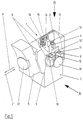
- An electrical switch 1 for regulating the speed of electric motors which is used in particular in electric hand tools with clockwise and anti-clockwise rotation, such as drills, rotary hammers, and the like. the like, is used, is shown schematically in Fig. 1.
- the switch 1 has a switch housing 2, in which a circuit board 3 is arranged.
- the electrical and electronic components 4 of a circuit arrangement for the speed control of the electric motor are located on the printed circuit board 3.
- This circuit arrangement can be a phase control which is known per se, as described, for example, in DE-OS 3219476.
- the switch 1 shown in FIG. 1 also has an actuating element designed as a pusher 5, which is adjustably mounted on the switch housing 2, and an actuating plunger 6 attached to it and leading into the interior of the switch 1.
- the pusher 5 can be moved manually in the direction of the arrow 7 'are moved against a compression spring, not shown, so that it returns to the starting position according to arrow 7 after release.
- the switch 1 there is a contact rocker 8, by means of which an electrical contact is made when the push button 5 is actuated.
- a switching cam 9 located on the actuating plunger 6 acts on one end 10 of the contact rocker 8, so that the contact connection between the other end 10 'of the contact rocker 8 and the connection contact 11 is opened.
- the switching cam 9 releases the end 10 of the contact rocker 8 and a tension spring 12 pulls the other end 10 'of the contact rocker 8 to the connection contact 11, so that the electrical connection is now closed.
- an extension 13 with a grinder 14 attached to it is arranged on the actuating plunger 6.
- One end of this grinder 14 slides on a resistance track 15 located on the printed circuit board 3, with which the grinder 14 and the resistance track 15 form a potentiometer 16.
- the electrical resistance corresponding to the respective position of the potentiometer 16, which is thus correlated to the respective position of the push button 5, is used for speed adjustment and control of the electric motor by means of the circuit arrangement located on the printed circuit board 3.
- the respective speed of the electric motor is dependent on the position of the pusher 5 and can be set up to a maximum speed, which corresponds to the maximum possible displacement of the pusher 5 in the direction 7 'and at which the full voltage is applied to the electric motor.
- a preselectable maximum speed which is on the one hand less than or equal to the maximum speed and on the other hand greater than or equal to a minimum speed depending on the switch design.
- This can be the case with drilling machines, for example in screwdriver operation, where the speed when screwing on is increased from zero to a preselected greatest speed, the preselected greatest speed depending on the material of the workpiece, the size of the screw and the like.
- the electrical switch 1 has a device for presetting a maximum speed, which is between the minimum and maximum speed.
- This device for presetting a maximum speed has an adjusting wheel 21 which is rotatably mounted on the front of the pusher 5 and which allows the maximum speed to be preselected by means of a rotary setting.
- the adjusting wheel 21 can be used to linearly adjust a slide 22 provided with a stop cam 23, which is guided in a recess 26 on a lateral surface of the switch housing 2.
- a threaded screw 24 projecting into the inside of the pusher 5 is connected to the adjusting wheel 21 and engages in a threaded counterpart 25 of the pusher 22 located on the end of the pusher 22 facing the pusher 5.
- the slide 22 and thus also the stop cam 23 can then be adjusted in the direction of the arrows 7 and 7 'by rotating the adjusting wheel 21.
- the slide 22, which is connected to the pusher 5 via the threaded screw 24 and the threaded counterpart 25, is also moved in the direction of the arrow 28 in the recess 26.
- the pusher 5 can then be moved until the stop cam 23 comes to rest against the front surface 44 of the switch housing 2. In this position, the electric motor runs at the highest speed selected by the setting wheel 21.
- the trigger 5 can run through the full adjustment path when actuated until the stop cam 23 comes to rest comes to the front surface 44 of the switch housing 2.
- the preselected highest speed is thus the maximum speed.
- the stop cam 23 is set with the help of the adjusting wheel 21 away from the inner surface of the pusher 5 in the direction of the switch housing 2, then the pusher 5 can only part of its full adjustment path until the stop cam 23 abuts the front surface 44 of the switch housing Run through 2 so that the preselected highest speed is less than the maximum speed.
- the minimum speed that can be set with the setting wheel 21 is consequently determined by the extent to which the stop cam 23 can be set in the direction of the switch housing 2 by means of the setting wheel 21.
- the electrical switch 1 also has a locking device for mechanically locking the actuating member in the position which corresponds to the preselected highest speed.
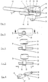
- the locking device consists of a locking lever 30 shown in greater detail in FIGS. 2 and 3, which cooperates with the slide 22, and a guide sleeve 29.
- the guide sleeve 29 is arranged on the side surface 45 of the switch housing 2 in the region of the end of the recess 26 facing the pusher 5 such that it engages over the recess 26, as a result of which the slide 22 can be moved freely in the recess 26 by the guide sleeve 29.
- the locking pusher 30 is movably mounted in the guide sleeve 29 against the force of a compression spring, not shown, in the direction perpendicular to the side surface 45 of the switch housing 2 and has a mandrel 32 facing the recess 26, which ends in a thickened end 33, as shown in FIGS 6 and 7 can be seen.
- the slide 22 is in turn provided with a recess 31, which is located in the region of the guide sleeve 29 when the pusher 5 is moved up to the maximum speed preselected by means of the adjusting wheel 21.
- the mandrel 32 can engage in the recess 31 by pressing in the locking lever 30, which is shown in FIGS. 5 and 6. If the pusher 5 is now released, it tries to move back with the slide 22 due to the spring pressure in the direction of the arrow 7, but the thickened end 33 hooks into the recess 31, as can be seen in more detail in FIG. 7, and so the further movement of the push button 5 ends. In this position, the pusher 5 then remains locked and the electric motor runs at the preselected highest speed without the pusher 5 having to be held manually.
- the pusher 5 is pressed again in the direction of the arrow 7 ', the slide 22 likewise moving in the direction of the arrow 7' according to FIG. 7, which is possible because the recess 31 is dimensioned larger than the size of the mandrel 32 by an appropriate overtravel 35. Due to the spring pressure exerted on the locking lever 30, the thickened end 33 jumps out of the recess 31, whereby the locking is released so that the lever 5 can be freely moved back in the direction of the arrow 7 (see FIG. 1 or 2).
- a changeover switch 18 for the right-left running of the electric motor is also latched, as can be seen in more detail in FIG. 2.
- This switch 18 has a switch lever 19 which protrudes slightly above the pusher 5.
- the switch lever 19 can be moved in two positions, namely in a first for clockwise rotation and in a second for counterclockwise rotation.
- the circuit to the electric motor is connected via leads which are connected to the plug contacts 20 so that the electric motor runs on the right or left.
- the brushes of the electric motors which are used in particular in electric hand tools, are generally set for the clockwise rotation from the neutral position in a preferred direction, which increases the torque in the clockwise rotation. However, this reduces the power that can be achieved in counterclockwise rotation without overloading the electric motor.
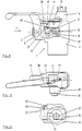
- the electrical switch 1 also has a device for limiting the speed in the counterclockwise rotation to a speed that is less than the maximum speed is, namely usually to a speed that is approximately half of the maximum speed. This device has a stroke limit stop 36 which is fastened inside the pusher 5.
- the device for preventing locking in counterclockwise rotation Integrated in this device for limiting the speed in counterclockwise rotation is the device for preventing locking in counterclockwise rotation.
- the stroke limit stop 36 and the stop cam 23 in counterclockwise rotation cooperate with the corresponding stops on the device for preventing locking in the counterclockwise rotation, which consist of a protruding projection 42 and a stop pin 43, as will be explained in more detail below, so that the The largest possible adjustment path of the pusher 5 in the counterclockwise rotation is preferably limited to approximately half the maximum possible adjustment path in the clockwise rotation. Consequently, a reduction in the maximum speed in counterclockwise rotation is achieved.
- the device for preventing locking in the counterclockwise rotation consists of a lever 37 which is rotatably mounted in a recess 40 on the top 17 of the switch housing 2 by means of a pin 38 engaging in a hole in the switch housing 2.
- a pin can of course also be attached to the top 17 of the switch housing 2 and this pin can engage in a hole in the lever 37.
- the lever 37 has two lever arms running parallel to the upper side 17 of the switch housing 2 in the recess 40, the first lever arm 34 in the direction facing away from the handle 5 and the second lever arm 34 'in the direction facing towards the handle 5 is arranged (see also Fig. 8).
- the second lever arm 34 ′ of the lever 37 ends on the side opposite the pin 38 approximately at the front edge of the switch housing 2. At this end an arm 41 extends approximately 90 degrees and runs parallel to the front surface 44 of the switch housing 2 (see also also Fig. 2).
- This arm 41 has a protruding projection 42, which is located approximately at the same height as the stroke limitation stop 36 and extends essentially parallel to the second lever arm 34 ′ of the lever 37.
- the approximately rectangular cross section of the angled arm 41 forms an angle ⁇ with the second lever arm 34 'of the lever 37, as can be seen in FIG. 8. This is preferably located Angle ⁇ at approximately 120 to 150 degrees. This has the advantage that the angled arm 41 in the counterclockwise position with its surface facing the switch housing 2 lies against the entire front surface of the switch housing 2 and can be supported there (compare FIGS. 2 and 3).
- the changeover switch 18 is in the counterclockwise direction and the adjusting wheel 21 is preset to one extreme position, namely maximum speed, as a result of which the stop cam 23 on the slide 22 is in its position closest to the pusher 5. If the pusher 5 is now moved according to the direction arrow 7 ', the stroke limit stop 36 comes into contact with the protruding shoulder 42 of the lever 37. As a result, the pusher 5 can no longer be moved and the greatest speed that can be set by actuating the pusher 5 becomes Counterclockwise rotation is limited to a lower speed than the maximum speed.
- the size of the stroke limit stop 36 and the protruding shoulder 42 is selected so that this maximum adjustable speed in the left-hand rotation is approximately half the maximum speed.
- the size of the stop pin 43 will preferably be selected so that on the one hand the minimum speed is only slightly reduced in the counterclockwise rotation and on the other hand one Engagement of the thickened end 33 in the recess 31 is just not possible. In this way, even with a pre-selected minimum speed, an effective prevention of locking in the left-hand rotation is achieved.
- the thickened end 33 of the mandrel 32 of the locking lever 30 can engage in the recess 31 on the slide 22 in none of these positions, so that the locking device engages in all presettable positions of the adjusting wheel 21 in the counterclockwise rotation is prevented.
- the locking device engages in all presettable positions of the adjusting wheel 21 in the counterclockwise rotation is prevented.
- the size of the stroke limit stop 36 is coordinated with the protruding shoulder 42 for counterclockwise rotation so that the stroke limit stop 36 does not yet touch the front surface of the switch housing 2 or at most just touches it when the trigger 5 is set for maximum speed in clockwise rotation. A reduction in the speed due to the stroke limit stop 36 can therefore not occur in clockwise rotation and the maximum adjustment path of the pusher 5 is only determined by the abutment cam 23 resting on the front surface 44 of the switch housing 2, as already described above.
Description
Die Erfindung betrifft einen elektrischen Schalter zur Drehzahlregulierung von Motoren, insbesondere von Elektromotoren an Elektrohandwerkzeugen nach dem Oberbegriff des Patentanspruchs 1.The invention relates to an electrical switch for regulating the speed of motors, in particular electric motors on electric hand tools, according to the preamble of
An Elektrohandwerkzeugen, wie Bohrmaschinen, Schrauber, u.dgl., sind häufig Schalter angeordnet, die eine Verstellung der Drehzahl zwischen Null und einer maximalen Drehzahl gestatten. Für diesen Zweck kann das Betätigungsorgan unterschiedlich weit verstellt werden, wobei mittels einer elektronischen Schaltung die der jeweiligen Stellung des Betätigungsorgans entsprechende Drehzahl am Elektromotor eingestellt und weitgehend konstant gehalten wird. Ein solcher Schalter ist in der DE-OS 41 21 264 gezeigt.Switches are often arranged on electric hand tools, such as drills, screwdrivers, and the like, which allow the speed to be adjusted between zero and a maximum speed. For this purpose, the actuating member can be adjusted to different extents, the speed of the electric motor corresponding to the respective position of the actuating member being set and kept largely constant by means of an electronic circuit. Such a switch is shown in DE-OS 41 21 264.
In manchen Fällen, beispielsweise dem Bohr- oder Schrauberbetrieb, ist es wünschenswert, daß die Drehzahl lediglich bis zu einer vorwählbaren größten Drehzahl verstellbar ist, die jedoch einerseits kleiner oder auch gleich der maximalen Drehzahl des Elektrohandwerkzeugs und andererseits größer oder auch gleich einer von der Schalterauslegung abhängigen minimalen Drehzahl des Elektrohandwerkzeugs ist. Dazu besitzen diese Schalter Einrichtungen zur Voreinstellung einer größten Drehzahl, die den Verstellweg des Betätigungsorgans auf eine Strecke begrenzen, die kleiner oder auch gleich dem maximal möglichen Verstellweg ist. In den meisten Fälen besitzen solche Schalter zusätzlich eine mechanische Arretiereinrichtung, mit der das Betätigungsorgan in ungefähr der der vorgewählten größten Drehzahl entsprechenden Stellung festgestellt werden kann. Dann braucht der Benutzer das Betätigungsorgan des Schalters im Dauerbetrieb des Elektrohandwerkzeuges nicht festzuhalten. Eine derartige Arretiereinrichtung ist aus der DE-OS 24 10 871 bekannt.In some cases, for example drilling or screwdriver operation, it is desirable that the speed can only be adjusted up to a preselectable maximum speed, which, on the one hand, is less than or equal to the maximum speed of the electric hand tool and, on the other hand, greater than or equal to one of the switch design dependent minimum speed of the electric hand tool. For this purpose, these switches have devices for presetting a maximum speed, the limit the adjustment path of the actuator to a distance that is less than or equal to the maximum possible adjustment path. In most cases, such switches additionally have a mechanical locking device with which the actuating member can be locked in approximately the position corresponding to the preselected highest speed. Then the user does not need to hold the actuator of the switch in continuous operation of the electric hand tool. Such a locking device is known from DE-OS 24 10 871.
Beispielsweise kann der Benutzer beim Bohren die größte Drehzahl, die dem zu bohrenden Material angepaßt ist, zunächst am Schalter voreinstellen. Durch Bewegung des Betätigungsorgans kann dann sanft angebohrt und die Bohrerdrehzahl bis zu dieser vorgewählten größten Drehzahl gesteigert werden. In der Stellung der vorgewählten größten Drehzahl kann anschließend das Betätigungsorgan arretiert werden, so daß der Benutzer das Betätigungsorgan beim weiteren Bohren nicht mehr länger festhalten muß.For example, when drilling, the user can first preset the highest speed that is adapted to the material to be drilled at the switch. The actuator can then be gently tapped and the drill speed increased up to this preselected maximum speed. In the position of the preselected highest speed, the actuator can then be locked so that the user no longer has to hold the actuator when drilling further.
Häufig können Elektrohandwerkzeuge in zwei entgegengesetzte Drehrichtungen betrieben werden, d.h. sie besitzen einen Rechts- und Linkslauf. Beispielsweise lassen sich im Schrauberbetrieb dann Schrauben in ein Material sowohl ein- als auch ausdrehen. Zur Umstellung zwischen dem Rechts- und Linkslauf ist am Schalter ein zusätzlicher Umschalter angeordnet, der vorzugsweise mittels eines in der Nähe des Betätigungsorgans angeordneten Betätigungshebels betätigt wird.Electric hand tools can often be operated in two opposite directions, i.e. they have clockwise and anti-clockwise rotation. For example, in screwdriver operation, screws can be screwed in and out of a material. To switch between clockwise and counterclockwise rotation, an additional switch is arranged on the switch, which is preferably actuated by means of an actuating lever arranged in the vicinity of the actuating member.
Ein Elektrowerkzeug gemäß Oberbegriff von Patentanspruch 1 mit einem ein verstellbares Betätigungsorgan sowie eine Arretiereinrichtung besitzenden Schalter, der zusätzlich mit einem Umschalter für den Rechts- und Links-Lauf versehen ist, ist aus der DE-A-27 55 960 bekannt. Am Betätigungshebel des Umschalters ist ein Stift befestigt, der im Linkslauf unter den Arretierriegel der Arretiereinrichtung greift, so daß eine Betätigung des Arretierriegels verhindert ist. Dadurch soll die Unfallgefahr durch eine falsche Drehrichtung bei Verwendung eines Vorsatzgerätes am Elektrowerkzeug ausgeschaltet werden. Auf sonstige Probleme im Zusammenhang mit dem Arretierriegel gibt diese Offenlegungsschrift keinen Hinweis.A power tool according to the preamble of
Bei Elektrohandwerkzeugen werden in der Regel sogenannte Universalmotoren verwendet. Bei diesen Universalmotoren sind die Bürsten, die dem Ankter den Strom über den Kollektor zuführen, mit einem gewissen Winkel aus der neutralen Lage verstellt, um im Rechtslauf eine Erhöhung des Drehmoments und damit der Leistung zu erzielen. Wird ein solcher Elektromotor jedoch im Linkslauf betrieben, so ist diese Bürstenstellung äußerst ungünstig und kann bei voller Leistungsaufnahme zum sogenannten Bürstenfeuer führen, was letztendlich zur Zerstörung der Bürsten und des Kollektors und folglich zum frühzeitigen Ausfall des gesamten Motors führen kann. Da jedoch der Rechtslauf der Regelbetrieb bei einem Elektrohandwerkzeug ist, will man auf die durch Verstellung der Bürsten erzielte Leistungssteigerung im allgemeinen nicht verzichten.So-called universal motors are generally used for electric hand tools. With these universal motors, the brushes that supply the anchor with the current via the collector are adjusted at a certain angle from the neutral position in order to increase the torque and thus the power in clockwise rotation. However, if such an electric motor is operated in counterclockwise rotation, this brush position is extremely unfavorable and can lead to so-called brush fire when the power is fully consumed, which can ultimately destroy the brushes and the collector and consequently lead to the premature failure of the entire motor. However, since clockwise rotation is the standard operation for an electric hand tool, one generally does not want to do without the increase in performance achieved by adjusting the brushes.
Zur Vermeidung des ungünstigen Bürstenfeuers ist es an sich bekannt, den Elektromotor im Linkslauf nicht mit voller Leistung zu betreiben, sondern dort die Leistungsaufnahme auf eine unschädliche Größe zu reduzieren. Dies wird mit einer Einrichtung zur Begrenzung der Drehzahl im Linkslauf erreicht, mit deren Hilfe die größte einstellbare Drehzahl im Linkslauf so begrenzt wird, daß sie kleiner als die maximale Drezahl im Rechtslauf ist. Eine derartige Einrichtung zur Begrenzung der Drehzahl im Linkslauf ist in der DE-OS 33 42 412 gezeigt und besteht aus einem im Linkslauf wirksamen Anschlag am Betätigungsorgan, wobei mittels des Anschlags die Größe des Verstellweges des Betätigungsorgans im Linkslauf entsprechend verringert wird. In der Regel wird die Größe des Verstellweges so gewählt, daß im Linkslauf eine Begrenzung auf ungefähr die halbe maximale Drehzahl des Rechtslaufes vorliegt.In order to avoid the unfavorable brush fire, it is known per se not to operate the electric motor counterclockwise at full power, but to reduce the power consumption to a harmless size there. This is achieved with a device for limiting the speed in counterclockwise rotation, with the aid of which the largest adjustable speed in counterclockwise rotation is limited so that it is less than the maximum speed in clockwise rotation. Such a device for limiting the speed in counterclockwise rotation is in the DE-OS 33 42 412 shown and consists of an effective counterclockwise stop on the actuating member, the size of the adjustment path of the actuating member in counterclockwise rotation is correspondingly reduced by means of the stop. As a rule, the size of the adjustment path is selected so that there is a limitation in the counterclockwise rotation to approximately half the maximum speed of the clockwise rotation.
Wie aus der DE-OS 24 10 871 hervorgeht, besitzt die Arretiereinrichtung einen vom Benutzer betätigbaren federbelasteten Riegel, der dann in eine Aussparung an der Einrichtung zur Voreinstellung einer größten Drehzahl eingreifen kann, wenn das Betätigungsorgan in die dieser größten Drehzahl entsprechende Stellung gebracht ist. Bei betätigter Arretiereinrichtung hält der Riegel dann das Betätigungsorgan in dieser Stellung fest. Es hat sich nun gezeigt, daß für den Fall, daß die an der Einrichtung zur Voreinstellung einer größten Drehzahl vorgewählte Drehzahl kleiner als die maximale Drehzahl ist, beim Linkslauf mit Drehzahlbegrenzung in der betätigten Arretiereinrichtung eine unlösbare Verhakung auftreten kann. In einem solchen Fall ist dann weder eine Lösung der Arretierung noch ein Ausschalten des Schalters möglich, womit der Schalter letztendlich unbrauchbar wird. Es ist weiter unmittelbar ersichtlich, daß dann auch beträchtliche Unfallgefahren von dem mittels des Schalters nicht mehr ausschaltbaren Elektrohandwerkzeug ausgehen.As is apparent from DE-OS 24 10 871, the locking device has a user-operated spring-loaded latch, which can then engage in a recess in the device for presetting a maximum speed when the actuator is brought into the position corresponding to this maximum speed. When the locking device is actuated, the bolt then holds the actuating member in this position. It has now been shown that in the event that the speed selected on the device for presetting a maximum speed is less than the maximum speed, an unreleasable hooking can occur in the actuated locking device when rotating counterclockwise. In such a case, it is then neither possible to release the lock nor to switch the switch off, which ultimately makes the switch unusable. It can also be seen immediately that considerable accident hazards then also emanate from the electrical hand tool which can no longer be switched off by means of the switch.
Ausgehend von diesem Stand der Technik liegt der Erfindung die Aufgabe zugrunde, den elektrischen Schalter zur Drehzahlregulierung von Motoren so zu verbessern, daß eine unlösbare Verhakung der Arretiereinrichtung im Linkslauf mit Drehzahlbegrenzung nicht mehr auftreten kann.Based on this prior art, the invention has for its object to improve the electrical switch for speed control of motors so that an indissoluble hooking of the locking device in counterclockwise rotation with speed limitation can no longer occur.
Diese Aufgabe wird bei einem gattungsgemäßen elektrischen Schalter durch die kennzeichnenden Merkmale des Anspruchs 1 gelöst.This object is achieved in a generic electrical switch by the characterizing features of
Weitere Ausgestaltungen der Erfindung sind Gegenstand der Unteransprüche.Further embodiments of the invention are the subject of the dependent claims.
Es wurde gefunden, daß die bei herkömmlichen Schaltern im Linkslauf in bestimmten Stellungen des Betätigungsorgans und bei betätigter Arretiereinrichtung auftretenden unlösbaren Verhakungen darauf zurückzuführen sind, daß aufgrund des wirksamen Anschlags im Betätigungsorgan, der sich in der Einrichtung zur Begrenzung der Drehzahl im Linkslauf befindet, das Spiel zwischen dem Riegel der Arretiereinrichtung und der Aussparung an der Einrichtung zur Voreinstellung einer größten Drehzahl entfällt oder zumindestens so klein wird, daß sich der Riegel nicht mehr aus der Aussparung lösen kann. Der Erfindung liegt davon ausgehend der Gedanke zugrunde, daß die Arretierung des Betätigungsorgans im Linkslauf verhindert wird. Damit bestehen die mit der Erfindung erzielten Vorteile insbesondere darin, daß aufgrund der erzielten Verhinderung von Verhakungen der Arretiereinrichtung im Linkslauf mit Drehzahlbegrenzung ein ansonsten mögliches Unbrauchbarwerden des Schalters nicht mehr vorkommen kann und die damit verbundenen Unfallgefahren wirksam gebannt sind.It has been found that the non-detachable interlocking which occurs in conventional switches in the counterclockwise rotation in certain positions of the actuating member and when the locking device is actuated is due to the fact that, due to the effective stop in the actuating member which is located in the device for limiting the speed in the counterclockwise rotation, the game between the bolt of the locking device and the recess on the device for presetting a maximum speed is eliminated or at least becomes so small that the bolt can no longer be released from the recess. On the basis of this, the invention is based on the idea that the locking of the actuating member in the counterclockwise direction is prevented. Thus, the advantages achieved by the invention are, in particular, that an otherwise possible uselessness of the switch can no longer occur due to the prevention of jamming of the locking device in counterclockwise rotation with speed limitation and the associated accident risks are effectively eliminated.
Herkömmliche Schalter zur Drehzahlregulierung mit einem im Linkslauf wirksamen, am Betätigungsorgan befindlichen Anschlag zur Drehzahlbegrenzung neigen zum Kippen des Betätigungsorgans bei Anliegen an diesem Anschlag, womit ein unerwünschtes Schwanken der Drehzahl einhergeht. Diese Kippwirkung wird beim erfindungsgemäßen Schalter weitgehend reduziert. Weiter wirken sich bei einem herkömmlichen Schalter auch Toleranzen in der Anordnung des Umschalters für den Rechts-Links-Lauf sowie dessen Betätigungshebels auf die Drehzahlbegrenzung aus. Derartige Toleranzen werden bei der Erfindung weitgehend eliminiert.Conventional switches for speed regulation with an anti-clockwise stop on the actuating member for speed limitation tend to tilt the actuating member when this stop is present, which is accompanied by an undesirable fluctuation in the rotational speed. This tilting effect is largely reduced in the switch according to the invention. In a conventional switch, tolerances in the arrangement of the switch for right-left rotation and its actuating lever also have an effect on the speed limitation. Such tolerances are largely eliminated in the invention.
Da in einer weiteren Ausgestaltung der Erfindung nur ein einziges zusätzliches Teil gegenüber herkömmlichen Schaltern verwendet wird, das zudem einfach ausgestaltet ist, handelt es sich um eine kostengünstige Lösung. Dieses zusätzliche Teil ist so ausgebildet, daß es sich in der die Drehzahl im Linkslauf begrenzenden Stellung des Betätigungsorgans an einer Fläche des Schaltergehäuses abstützt, so daß auch große vom Benutzer auf das Betätigungsorgan ausgeübte Kräfte nicht zur vorzeitigen Zerstörung dieses Teils führen können.Since in a further embodiment of the invention only a single additional part is used compared to conventional switches, which is also simple, it is an inexpensive solution. This additional part is designed so that it is supported on the surface of the switch housing in the position of the actuating member which limits the counterclockwise rotation, so that even large forces exerted by the user on the actuating member cannot lead to the premature destruction of this part.
Ein Ausführungsbeispiel der Erfindung ist in den Zeichnungen dargestellt und wird im folgenden näher beschrieben.An embodiment of the invention is shown in the drawings and will be described in more detail below.
Es zeigen
- Fig. 1
- eine schematische Darstellung eines erfindungsgemäßen Schalters in perspektivischer und teilweise aufgeschnittener Ansicht, wobei der Umschalter für den Rechts-Links-Lauf der Übersichtlichkeit halber weggelassen ist,
- Fig. 2
- den Schalter zusätzlich mit Umschalter für den Rechts-Links-Lauf in Seitenansicht entsprechend der Richtung A in Fig. 1, teilweise aufgeschnitten,
- Fig. 3
- eine Draufsicht auf den Schalter in Linkslauf-Stellung entsprechend der Richtung B in Fig. 1,
- Fig. 4
- eine Draufsicht auf den Schalter wie in Fig. 3, jedoch in Rechtslauf-Stellung,
- Fig. 5
- einen Ausschnitt aus der Arretiereinrichtung in Seitenansicht,
- Fig. 6
- einen Schnitt entsprechend der Linie 6-6 aus Fig. 5 in noch nicht arretierter Stellung
- Fig. 7
- einen Schnitt wie in Fig. 6, jedoch in arretierter Stellung,
- Fig. 8
- eine Draufsicht auf den in der Einrichtung zur Verhinderung der Arretierung im Linkslauf befindlichen Hebel in vergrößerter Darstellung,
- Fig. 9
- den in Linkslauf-Stellung befindlichen Schalter in Seitenansicht entsprechend der Richtung A aus Fig. 1 und teilweise aufgeschnitten, wobei die Einrichtung zur Voreinstellung einer größten Drehzahl auf maximale Drehzahl eingestellt ist,
- Fig. 10
- eine Draufsicht entsprechend der Richtung B aus Fig. 1 auf den Schalter in der Stellung nach Fig. 9,
- Fig. 11
- eine vergrößerte Seitenansicht auf die die Arretiereinrichtung in der Stellung des Schalters nach Fig. 9 und
- Fig. 12
bis 14 - den in Linkslauf-Stellung befindlichen Schalter in den den Fig. 9
bis 11 entsprechenden Ansichten, wobei die Einrichtung zur Voreinstellung einer größten Drehzahl auf minimale Drehzahl eingestellt ist.
- Fig. 1
- 2 shows a schematic illustration of a switch according to the invention in a perspective and partially cutaway view, the switch for the right-left running being omitted for the sake of clarity,
- Fig. 2
- the switch additionally with switch for the right-left run in side view corresponding to the direction A in Fig. 1, partially cut away,
- Fig. 3
- 2 shows a plan view of the switch in the counterclockwise rotation position in the direction B in FIG. 1,
- Fig. 4
- a plan view of the switch as in Fig. 3, but in the clockwise position,
- Fig. 5
- a section of the locking device in side view,
- Fig. 6
- a section along the line 6-6 of FIG. 5 in the not yet locked position
- Fig. 7
- 6 shows a section as in FIG. 6, but in the locked position,
- Fig. 8
- a plan view of the lever located in the device for preventing the locking in the left rotation in enlarged view,
- Fig. 9
- the switch in the counterclockwise position in side view corresponding to the direction A of Fig. 1 and partially cut away, the device for presetting a maximum speed is set to maximum speed,
- Fig. 10
- 2 shows a plan view in the direction B from FIG. 1 of the switch in the position according to FIG. 9,
- Fig. 11
- an enlarged side view of the locking device in the position of the switch according to FIGS. 9 and
- 12 to 14
- the switch in the counterclockwise position in the views corresponding to FIGS. 9 to 11, wherein the device for presetting a maximum speed is set to minimum speed.
Dabei ist aus darstellerischen Gründen der in den Fig. 3, 4, 10 und 13 an sich nicht sichtbare Hebel der Einrichtung zur Verhinderung der Arretierung im Linkslauf mit durchgezogenen Linien eingezeichnet.For illustrative reasons, the lever of the device for preventing the locking in the left-hand rotation, which is not visible in FIGS. 3, 4, 10 and 13, is shown with solid lines.
Ein elektrischer Schalter 1 zur Drehzahlregulierung von Elektromotoren, der insbesondere in Elektrohandwerkzeugen mit Rechts- und Linkslauf, wie beispielsweise Bohrmaschinen, Bohrhämmer, u. dgl., eingesetzt wird, ist in Fig. 1 schematisch dargestellt. Der Schalter 1 besitzt ein Schaltergehäuse 2, in welchem eine Leiterplatte 3 angeordnet ist. Auf der Leiterplatte 3 befinden sich die elektrischen und elektronischen Bauelemente 4 einer Schaltungsanordnung für die Drehzahlregelung des Elektromotors. Bei dieser Schaltungsanordnung kann es sich um eine an sich bekannte Phasenanschnittssteuerung handeln, wie sie beispielsweise in der DE-OS 3219476 beschrieben ist.An
Der in Fig. 1 dargestellte Schalter 1 besitzt weiter ein als Drücker 5 ausgebildetes Betätigungsorgan, das verstellbar am Schaltergehäuse 2 gelagert ist, und einen daran befestigten, in das Innere des Schalters 1 führenden Betätigungsstößel 6. Der Drücker 5 kann manuell in Richtung des Pfeiles 7' gegen eine nicht dargestellte Druckfeder bewegt werden, so daß er nach Loslassen wieder in die Ausgangsstellung entsprechend dem Pfeil 7 zurückkehrt.The
Im Schalter 1 befindet sich eine Kontaktwippe 8, mit deren Hilfe bei Betätigung des Drückers 5 ein elektrischer Kontakt hergestellt wird. In unbetätigtem Zustand des Drückers 5 wirkt ein am Betätigungsstößel 6 befindlicher Schaltnocken 9 auf das eine Ende 10 der Kontaktwippe 8 ein, so daß die Kontaktverbindung zwischen dem anderen Ende 10' der Kontaktwippe 8 und dem Anschlußkontakt 11 geöffnet ist. Bei Betätigung des Drückers 6 gibt der Schaltnocken 9 das Ende 10 der Kontaktwippe 8 frei und eine Zugfeder 12 zieht das andere Ende 10' der Kontaktwippe 8 an den Anschlußkontakt 11, so daß die elektrische Verbindung nunmehr geschlossen ist.In the
Im Inneren des Schalters 1 ist am Betätigungsstößel 6 ein Ansatz 13 mit einem hieran befestigten Schleifer 14 angeordnet. Dieser Schleifer 14 gleitet mit einem Ende auf einer auf der Leiterplatte 3 befindlichen Widerstandsbahn 15, womit der Schleifer 14 und die Widerstandsbahn 15 ein Potentiometer 16 bilden. Durch Bewegung des Drückers 5 wird der Schleifer 14 linear auf der Widerstandsbahn 15 bewegt und damit die Stellung des Potentiometers 16 verändert. Der der jeweiligen Stellung des Potentiometers 16 entsprechende elektrische Widerstand, der somit in Korrelation zu der jeweiligen Stellung des Drückers 5 steht, dient zur Drehzahleinstellung und -regelung des Elektromotors mittels der auf der Leiterplatte 3 befindlichen Schaltungsanordnung.Inside the
Die jeweilige Drehzahl des Elektromotors ist abhängig von der Stellung des Drückers 5 und läßt sich bis zu einer maximalen Drehzahl einstellen, die der maximal möglichen Verschiebung des Drückers 5 in Richtung 7' entspricht und bei der die volle Spannung am Elektromotor anliegt. In manchen Fällen ist es wünschenswert, die Drehzahl nur bis zu einer vorwählbaren größten Drehzahl variieren zu können, die einerseits kleiner oder gleich als die maximale Drehzahl und andererseits größer oder gleich als eine von der Schalterauslegung abhängige minimale Drehzahl ist. Dies kann bei Bohrmaschinen beispielsweise im Schrauberbetrieb der Fall sein, wo die Drehzahl beim Anschrauben von Null bis zu einer vorgewählten größten Drehzahl gesteigert wird, wobei die vorgewählte größte Drehzahl abhängig vom Material des Werkstücks, der Größe der Schraube u. dgl., jedoch in der Regel weitaus geringer als die maximale Drehzahl ist. Zu diesem Zweck besitzt der elektrische Schalter 1 eine Einrichtung zur Voreinstellung einer größten Drehzahl, die zwischen der minimalen und maximalen Drehzahl liegt.The respective speed of the electric motor is dependent on the position of the
Diese Einrichtung zur Voreinstellung einer größten Drehzahl besitzt ein drehbar an der Vorderseite des Drückers 5 gelagertes Stellrad 21, das durch Dreheinstellung die Vorwahl der größten Drehzahl gestattet. Wie näher in Fig. 2 gezeigt ist, läßt sich mit Hilfe des Stellrades 21 ein mit einem Anschlagnocken 23 versehener Schieber 22, der in einer Vertiefung 26 an einer seitlichen Oberfläche des Schaltergehäuses 2 geführt wird, linear-verstellen. Dazu ist mit dem Stellrad 21 eine ins Innere des Drückers 5 hineinragende Gewindeschraube 24 verbunden, die in ein an dem dem Drücker 5 zugewandten Ende des Schiebers 22 befindliches Gewindegegenstück 25 des Schiebers 22 eingreift. Durch Drehung des Stellrades 21 läßt sich dann der Schieber 22 und damit auch der Anschlagnocken 23 in Richtung der Pfeile 7 und 7' verstellen.This device for presetting a maximum speed has an
Wird der Drücker 5 manuell in Richtung des Pfeiles 7' bewegt, so wird der Schieber 22, der über die Gewindeschraube 24 und das Gewindegegenstück 25 mit dem Drücker 5 verbunden ist, in Richtung des Pfeiles 28 in der Vertiefung 26 mitbewegt. Der Drücker 5 läßt sich dann soweit bewegen, bis der Anschlagnocken 23 zur Anlage an die vordere Fläche 44 des Schaltergehäuses 2 kommt. In dieser Stellung läuft der Elektromotor mit der vom Stellrad 21 vorgewählten größten Drehzahl.If the
Ist das Stellrad 21 so eingestellt, daß der Anschlagnocken 23 mit seiner dem Schaltergehäuse 2 abgewandten Fläche an einer Innenfläche des Drückers anliegt, wie in Fig. 2 gezeigt ist, dann kann der Drücker 5 bei Betätigung den vollen Verstellweg durchlaufen bis der Anschlagnocken 23 zur Anlage an die vordere Fläche 44 des Schaltergehäuses 2 kommt. Bei dieser Einstellung des Stellrades 21 ist somit die vorgewählte größte Drehzahl gerade die maximale Drehzahl. Ist der Anschlagnocken 23 mit Hilfe des Stellrades 21 von der Innenfläche des Drückers 5 weg in Richtung auf das Schaltergehäuse 2 zu eingestellt, so kann der Drücker 5 nur noch einen Teil seines vollen Verstellweges bis zur Anlage des Anschlagnockens 23 an die vordere Fläche 44 des Schaltergehäuses 2 durchlaufen, so daß die vorgewählte größte Drehzahl kleiner als die maximale Drehzahl ist. Die minimale Drehzahl, die mit dem Stellrad 21 einstellbar ist, ist folglich dadurch bestimmt, inwieweit der Anschlagnocken 23 mittels des Stellrades 21 in Richtung auf das Schaltergehäuse 2 verstellbar ist.If the
Der elektrische Schalter 1 besitzt weiter eine Arretiereinrichhtung zum mechanischen Feststellen des Betätigungsorgans in der Stellung, die der vorgewählten größten Drehzahl entspricht. Die Arretiereinrichtung besteht aus einem in Fig. 2 und 3 näher gezeigten Arretierdrücker 30, der mit dem Schieber 22 zusammenwirkt, und einer Führungshülse 29.The
Die Führungshülse 29 ist an der Seitenfläche 45 des Schaltergehäuses 2 im Bereich des dem Drücker 5 zugewandten Endes der Vertiefung 26 so angeordnet, daß sie die Vertiefung 26 übergreift, wodurch der Schieber 22 ungehindert von der Führungshülse 29 in der Vertiefung 26 bewegbar ist. Der Arretierdrücker 30 ist in der Führungshülse 29 gegen die Kraft einer nicht gezeigten Druckfeder in der auf die Seitenfläche 45 des Schaltergehäuses 2 senkrechten Richtung beweglich gelagert und besitzt einen der Vertiefung 26 zugewandten Dorn 32, der in ein verdicktes Ende 33 ausläuft, wie in den Fig. 6 und 7 zu sehen ist. Der Schieber 22 ist wiederum mit einer Ausnehmung 31 versehen, die sich bei Bewegung des Drückers 5 bis zu der mittels des Stellrades 21 vorgewählten größten Drehzahl gerade im Bereich der Führungshülse 29 befindet. Dadurch kann durch Eindrücken des Arretierdrückers 30 der Dorn 32 in die Ausnehmung 31 eingreifen, was in den Fig. 5 und 6 gezeigt ist. Wird der Drücker 5 nun losgelassen, so versucht dieser sich mit dem Schieber 22 aufgrund des Federdrucks wieder in Richtung des Pfeiles 7 zurückzubewegen, wobei sich jedoch das verdickte Ende 33 in die Ausnehmung 31 einhakt, wie in Fig. 7 näher zu sehen ist, und so die weitere Bewegung des Drückers 5 beendet. In dieser Stellung bleibt der Drücker 5 dann arretiert und der Elektromotor läuft mit der vorgewählten größten Drehzahl, ohne daß der Drücker 5 manuell festgehalten werden muß.The
Soll der arretierte Schalter 1 wieder ausgeschaltet werden, so wird der Drücker 5 erneut in Pfeilrichtung 7' gedrückt, wobei sich der Schieber 22 ebenfalls in Pfeilrichtung 7' gemäß Fig. 7 bewegt, was möglich ist, da die Ausnehmung 31 um einen zweckmäßigen Nachlaufweg 35 größer als die Größe des Dorns 32 bemessen ist. Aufgrund des auf den Arretierdrücker 30 ausgeübten Federdrucks springt das verdickte Ende 33 dabei aus der Ausnehmung 31 heraus, womit die Arretierung aufgehoben ist, so daß der Drücker 5 wieder frei in Pfeilrichtung 7 (siehe Fig. 1 oder 2) zurückbewegt werden kann.If the locked
Auf der Oberseite 17 des Schaltergehäuses 2 ist weiter ein Umschalter 18 für den Rechts-Links-Lauf des Elektromotors rastbar aufgesetzt, wie in Fig. 2 näher zu sehen ist. Dieser Umschalter 18 besitzt einen Umschalthebel 19, der etwas über den Drücker 5 übersteht. Der Umschalthebel 19 ist in zwei Stellungen bewegbar, nämlich in eine erste für den Rechtslauf und in eine zweite für den Linkslauf. Entsprechend der jeweiligen Stellung des Umschalthebels 19 ist der Stromkreis zum Elektromotor über Zuleitungen, die mit den Steckkontakten 20 verbunden sind, so geschaltet, daß der Elektromotor rechts oder links läuft.On the top 17 of the
Die Bürsten der Elektromotoren, die insbesondere in elektrischen Handwerkzeugen verwendet werden, werden in der Regel für den Rechtslauf aus der neutralen Stellung heraus in eine Vorzugsrichtung eingestellt, womit eine Erhöhung des Drehmoments im Rechtslauf erzielt wird. Dadurch sinkt jedoch die im Linkslauf ohne Überlastung des Elektromotors erzielbare Leistung. Zur Vermeidung einer übermäßigen Belastung des Motors im Linkslauf besitzt der elektrische Schalter 1 weiter eine Einrichtung zur Begrenzung der Drehzahl im Linkslauf auf eine Drehzahl die kleiner als die maximale Drehzahl ist, nämlich üblicherweise auf eine Drehzahl, die ungefähr die Hälfte der maximalen Drehzahl beträgt. Diese Einrichtung besitzt einen Hubbegrenzungsanschlag 36, der im Innern des Drückers 5 befestigt ist.The brushes of the electric motors, which are used in particular in electric hand tools, are generally set for the clockwise rotation from the neutral position in a preferred direction, which increases the torque in the clockwise rotation. However, this reduces the power that can be achieved in counterclockwise rotation without overloading the electric motor. To avoid excessive loading of the motor in the counterclockwise rotation, the
Integriert in diese Einrichtung zur Begrenzung der Drehzahl im Linkslauf ist die Einrichtung zur Verhinderung der Arretierung im Linkslauf. Dabei wirkt der Hubbegrenzungsanschlag 36 und der Anschlagnocken 23 im Linkslauf mit an der Einrichtung zur Verhinderung der Arretierung im Linkslauf befindlichen korrespondierenden Anschlägen, die aus einem abstehenden Ansatz 42 und einem Anschlagzapfen 43 bestehen, zusammen, wie im folgenden noch näher erläutert wird, so daß der größtmögliche Verstellweg des Drückers 5 im Linkslauf auf vorzugsweise ungefähr die Hälfte des im Rechtslauf maximal möglichen Verstellweges begrenzt wird. Folglich wird somit eine Reduzierung der maximalen Drehzahl im Linkslauf erreicht.Integrated in this device for limiting the speed in counterclockwise rotation is the device for preventing locking in counterclockwise rotation. The
Die Einrichtung zur Verhinderung der Arretierung im Linkslauf besteht aus einem Hebel 37, der in einer Vertiefung 40 an der Oberseite 17 des Schaltergehäuses 2 mittels eines in ein Loch im Schaltergehäuse 2 eingreifenden Zapfens 38 drehbar gelagert ist. Selbstverständlich kann auch umgekehrt ein Zapfen an der Oberseite 17 des Schaltergehäuses 2 angebracht sein und dieser Zapfen in ein Loch am Hebel 37 eingreifen. Der Hebel 37 besitzt zwei parallel zur Oberseite 17 des Schaltergehäuses 2 in der Vertiefung 40 verlaufende Hebelarme, wobei der erste Hebelarm 34 in die dem Drücker 5 abgewandte Richtung und der zweite Hebelarm 34' in die dem Drücker 5 zugewandte Richtung angeordnet ist (siehe auch Fig. 8). Am Ende des ersten Hebelarms 34 des Hebels 37 befindet sich ein abstehender Nocken 39, der wiederum in ein Langloch 46 eingreift, das sich in dem der Betätigungsseite abgewandten Arm 47 des Umschalthebels 19 befindet. Auch hier ist es wiederum möglich, den abstehenden Nocken 39 und das Langloch 46 zu vertauschen. Dadurch wird der Hebel 37 bei Betätigung des Umschalters 18 für den Rechts-Links-Lauf mittels des Umschalthebels 19 zwischen zwei Stellungen hin- und hergeschwenkt, wobei eine Stellung dem Rechts- und die andere dem Linkslauf zugeordnet ist. Die Stellung des Hebels 37 im Rechtslauf ist in Fig. 4 und diejenige im Linkslauf in Fig. 3 zu sehen.The device for preventing locking in the counterclockwise rotation consists of a
Der zweite Hebelarm 34' des Hebels 37 endet an der dem Zapfen 38 gegenüberliegenden Seite ungefähr an der Vorderkante des Schaltergehäuses 2. An diesem Ende geht ein ungefähr um 90 Grad abgewinkelter, parallel zur vorderen Fläche 44 des Schaltergehäuses 2 verlaufender Arm 41 ab (siehe dazu auch Fig. 2). Dieser Arm 41 besitzt einen abstehenden Ansatz 42, der sich ungefähr auf derselben Höhe wie der Hubbegrenzungsanschlag 36 befindet und im wesentlichen parallel zum zweiten Hebelarm 34' des Hebels 37 verläuft. Am abstehenden Ansatz befindet sich weiter ein Anschlagzapfen 43, der im wesentlichen parallel zum Arm 41 verläuft und sich ungefähr auf der Höhe des Anschlagnockens 23 des Schiebers 22 befindet.The
Der ungefähr rechteckförmige Querschnitt des abgewinkelten Arms 41 schließt einen Winkel α mit dem zweiten Hebelarm 34' des Hebels 37 ein, wie der Fig. 8 entnommen werden kann. Vorzugsweise liegt dieser Winkel α bei ungefähr 120 bis 150 Grad. Dies hat den Vorteil, daß der abgewinkelte Arm 41 in der Linkslauf-Stellung mit seiner dem Schaltergehäuse 2 zugewandten Fläche vollflächig an der vorderen Fläche des Schaltergehäuses 2 anliegt und sich dort abstützen kann (man vergleiche dazu Fig. 2 und 3).The approximately rectangular cross section of the
Im folgenden soll die Wirkungsweise der Einrichtung zur Begrenzung der Drehzahl im Linkslauf zusammen mit der integrierten Einrichtung zur Verhinderung der Arretierung im Linkslauf anhand der Fig. 9 bis 14 näher erläutert werden.The mode of operation of the device for limiting the speed in counterclockwise rotation together with the integrated device for preventing locking in counterclockwise rotation will be explained in more detail below with reference to FIGS. 9 to 14.
In den Fig. 9 bis 11 steht der Umschalter 18 auf Linkslauf und das Stellrad 21 ist auf die eine Extremposition, nämlich maximale Drehzahl voreingestellt, wodurch sich der Anschlagnocken 23 am Schieber 22 in seiner am nächsten dem Drücker 5 zugewandten Stellung befindet. Wird nun der Drücker 5 entsprechend dem Richtungpfeil 7' bewegt, so kommt der Hubbegrenzungsanschlag 36 in Anlage an den abstehenden Ansatz 42 des Hebels 37. Dadurch läßt sich der Drücker 5 nicht mehr weiterbewegen und die größte, durch Betätigung des Drückers 5 einstellbare Drehzahl wird im Linkslauf auf eine geringere Drehzahl als die maximale Drehzahl begrenzt. Vorzugsweise wird die Größe des Hubbegrenzungsanschlags 36 und des abstehenden Ansatzes 42 so gewählt, daß diese im Linkslauf größte einstellbare Drehzahl ungefähr die halbe maximale Drehzahl beträgt. Wie in den Fig. 9 und 11 weiter zu sehen ist, ist in dieser Stellung des Drückers 5, die die größte einstellbare Drehzahl im Linkslauf darstellt, der Anschlagnocken 23 am Schieber 22 vom Anschlagzapfen 43 entfernt. Auch die Ausnehmung 31 am Schieber 22 befindet sich noch nicht im Bereich des Dornes 32 des Arretierdrückers 30, so daß ein Eingreifen des verdickten Endes 33 in die Ausnehmung 31 und damit eine Arretierung im Linkslauf ausgeschlossen ist.9 to 11, the
In den Fig. 12 bis 14 ist nun die andere Extremposition im Linkslauf zu sehen, nämlich die Stellung, in der das Stellrad 21 auf minimale Drehzahl voreingestellt ist, wobei sich der Anschlagnocken 23 des Schiebers 22 in seiner am weitesten vom Drücker 5 entfernten Stellung befindet. Wird nun der Drücker 5 entsprechend dem Richtungpfeil 7' bewegt, so kommt der Anschlagnocken 23 des Schiebers 22 in Anlage an den Anschlagzapfen 43 des Hebels 37. Dadurch läßt sich der Drücker 5 ebenfalls nicht mehr weiterbewegen und die einstellbare Drehzahl wird im Links lauf dadurch wiederum auf eine geringere Drehzahl als die maximale Drehzahl begrenzt. Wie in den Fig. 12 und 14 weiter zu sehen ist, ist in dieser Stellung des Drückers 5, die die größte einstellbare Drehzahl im Linkslauf darstellt, der Hubbegrenzungsanschlag 36 vom abstehenden Ansatz 42 entfernt. Auch die Ausnehmung 31 am Schieber 22 befindet sich wiederum noch nicht vollständig im Bereich des Dornes 32 des Arretierdrückers 30, so daß ein Eingreifen des verdickten Endes 33 in die Ausnehmung 31 und damit eine Arretierung im Linkslauf ausgeschlossen ist.12 to 14, the other extreme position can be seen in the counterclockwise rotation, namely the position in which the
Da die minimale Drehzahl in der Regel bereits weit unterhalb der maximalen Drehzahl liegt, wird man die Größe des Anschlagzapfens 43 vorzugsweise so wählen, daß einerseits die minimale Drehzahl im Linkslauf lediglich wenig reduziert wird und andererseits jedoch ein Eingreifen des verdickten Endes 33 in die Ausnehmung 31 gerade noch nicht möglich ist. Somit wird auch bei vorgewählter minimaler Drehzahl eine wirksame Verhinderung der Arretierung im Linkslauf erzielt.Since the minimum speed is usually already far below the maximum speed, the size of the
Ist das Stellrad 21 in einer Zwischenstellung zwischen diesen beiden, in den Fig. 9 und 12 gezeigten Extrempositionen voreingestellt, so liegt bei in Pfeilrichtung 7' bewegten Drücker 5 im Linkslauf entweder der Anschlagnocken 23 des Schiebers 22 am Anschlagzapfen 43 des Hebels 37 an (siehe Fig. 12) oder der Hubbegrenzungsanschlag 36 am abstehenden Ansatz 42 des Hebels 37 (siehe Fig. 9). In bestimmten Einstellpositionen des Stellrades 21 kann es auch vorkommen, daß im Linkslauf der Anschlagnocken 23 am Anschlagzapfen 43 und gleichzeitig auch der Hubbegrenzungsanschlag 36 am abstehenden Ansatz 42 anliegen. Dadurch wird in allen Fällen eine Reduzierung der größten mittels des Drückers 5 einstellbaren Drehzahl im Linkslauf auf eine Drehzahl kleiner als die maximale Drehzahl gewährleistet. Wie anhand der Fig. 9 bis 14 beschrieben, kann weiter das verdickte Ende 33 des Dornes 32 des Arretierdrückers 30 in keiner dieser Positionen in die Ausnehmung 31 am Schieber 22 eingreifen, womit ein Einrasten der Arretiereinrichtung in allen voreinstellbaren Positionen des Stellrades 21 im Linkslauf wirksam verhindert wird. Vorteilhafterweise kann folglich dann auch im Linkslauf keine unlösbare Verhakung der Arretiereinrichtung in irgendeiner der am Stellrad 21 einstellbaren Positionen auftreten.If the
In der dem Rechtslauf zugeordneten Stellung des Umschalthebels 19 ist der Hebel 37 in die dem Linkslauf abgewandte Stellung verschwenkt, die in Fig. 4 näher zu sehen ist. In dieser Stellung ist der abgewinkelte Arm 41 des Hebels 37 außer Eingriff für den Hubbegrenzungsanschlag 36 und den Anschlagnocken 23, die sich asymmetrisch zur Mittellinie 48 des Schaltergehäuses 2 an der der Linkslauf-Stellung zugeordneten Seite des Schaltergehäuses 2 befinden. Damit können weder der Hubbegrenzungsanschlag 36 noch der Anschlagnocken 23 des Schiebers 22 bei Bewegung des Drückers 5 in Pfeilrichtung 7' in Anlage an den abstehenden Ansatz 42 bzw. Anschlagzapfen 43 kommen. Die Größe des Hubbegrenzungsanschlags 36 ist zusammen mit dem abstehenden Ansatz 42 für den Linkslauf so abgestimmt, daß der Hubbegrenzungsanschlag 36 bei Stellung des Drückers 5 für maximale Drehzahl im Rechtslauf die vordere Fläche des Schaltergehäuses 2 noch nicht berührt oder allenfalls gerade berührt. Eine Verminderung der Drehzahl aufgrund des Hubbegrenzungsanschlags 36 kann somit im Rechtslauf nicht auftreten und der maximale Verstellweg des Drückers 5 wird lediglich durch die Anlage des Anschlagnockens 23 an der vorderen Fläche 44 des Schaltergehäuses 2, wie bereits weiter oben beschrieben, festgelegt.In the position of the
- 1:1:
- Elektrischer SchalterElectrical switch
- 2:2:
- SchaltergehäuseSwitch housing
- 3:3:
- LeiterplatteCircuit board
- 4:4:
- Bauelemente (auf der Leiterplatte)Components (on the circuit board)
- 5:5:
- DrückerPusher
- 6:6:
- BetätigungsstößelActuating plunger
- 7, 7':7, 7 ':
- Richtungspfeile (manuelle Betätigung)Directional arrows (manual operation)
- 8:8th:
- KontaktwippeContact rocker
- 9:9:
- SchaltnockenSwitch cams
- 10,10':10.10 ':
- Ende der KontaktwippeEnd of the contact rocker
- 11:11:
- AnschlußkontaktConnection contact
- 12:12:
- ZugfederTension spring
- 13:13:
- Ansatz (am Betätigungsstößel)Approach (on the actuating plunger)
- 14:14:
- Schleifergrinder
- 15:15:
- WiderstandsbahnResistance track
- 16:16:
- PotentiometerPotentiometer
- 17:17:
- Oberseite (des Schaltergehäuses)Top (of the switch housing)
- 18:18:
- Umschalter für Rechts-Links-LaufSwitch for right-left running
- 19:19:
- UmschalthebelShift lever
- 20:20:
- SteckkontaktPlug contact
- 21:21:
- StellradAdjusting wheel
- 22:22:
- SchieberSlider
- 23:23:
- AnschlagnockenStop cam
- 24:24:
- GewindeschraubeThreaded screw
- 25:25:
- GewindegegenstückThread counterpart
- 26:26:
- Vertiefungdeepening
- 28:28:
- Richtungspfeil (für Bewegung Schieber)Direction arrow (for slide movement)
- 29:29:
- FührungshülseGuide sleeve
- 30:30:
- ArretierdrückerLocking lever
- 31:31:
- Ausnehmung (in Schieber)Recess (in slider)
- 32:32:
- Dorn (des Arretierungsdrückers)Thorn (of the locking lever)
- 33:33:
- verdicktes Ende (des Dorns)thickened end (of the thorn)
- 34,34':34.34 ':
- erster, zweiter Hebelarm (am Hebel)first, second lever arm (on the lever)
- 35:35:
- Nachlaufweg (in Ausnehmung des Schiebers)Overtravel (in the slider recess)
- 36:36:
- HubbegrenzungsanschlagStroke limit stop
- 37:37:
- Hebellever
- 38:38:
- ZapfenCones
- 39:39:
- Nockencam
- 40:40:
- Vertiefung (in Oberseite des Schaltergehäuses)Recess (in the top of the switch housing)
- 41:41:
- abgewinkelter Armangled arm
- 42:42:
- abstehender Ansatzprotruding approach
- 43:43:
- AnschlagzapfenStop pin
- 44:44:
- vordere Fläche (des Schaltergehäuses)front surface (of the switch housing)
- 45:45:
- Seitenfläche (des Schaltergehäuses)Side surface (of the switch housing)
- 46:46:
- Langloch (im Umschalthebel)Slot (in the switch lever)
- 47:47:
- Arm (des Umschalthebels)Arm of the switch lever
- 48:48:
- Mittellinie (des Schaltergehäuses)Center line (of the switch housing)
Claims (24)
- An electric switch (1) for regulating the speed of motors, particularly electric motors on electrically operated hand tools, with an actuating member (5) displaceably mounted on a switch housing whereby, by means of a preferably electronic circuit, a rotary speed is set at the motor which corresponds to the position of the actuating member, with a device for presetting a maximum speed which is less than or equal to a maximum and greater than or equal to a minimum speed, with a locking device which makes it possible to arrest the actuating member (5) in the position corresponding to the preset greatest speed, with a changeover switch (18) for left-hand or right-hand running ofthe motor, characterised by a device for limiting the speed in left-hand running and to a speed which is less than the maximum speed and, disposed on the switch (1), a device for preventing the locking function in left-hand running, the device for preventing locking in left-hand running co-operating, when the changeover switch (18) is set for left-hand running, with the device for limiting the speed in left-hand running and/or with the device for pre-setting a maximum speed.
- An electric switch according to claim 1, characterised in that the device for preventing locking in left-hand running is integrated into the device for limiting the speed in left-hand running.
- An electric switch according to claim 1 or 2, characterised in that the device for limiting the speed in left-hand running consists of a travel limiting device (36) disposed on the actuating member (5).
- An electric switch according to claim 1, 2 or 3, characterised in that the device for presetting a maximum speed consists of a sliding member (22) disposed for displacement on the actuating member (5) and on which there is an abutment projection (23) co-operating with the front face (14) of the switch housing (2).
- An electric switch according to claim 4, characterised in that the sliding member (22) has a recess (31) and the locking device has a locking push member (30) with a rod (32) which, in the locking instance, so engages the recess (31) that the thickened end (33) of the rod (32) fits into the recess (31).
- An electric switch according to one of claims 1 to 5, characterised in that the device for preventing locking in left-hand running is actuated by the changeover switch (18) for left and right-hand running.
- An electric switch according to claim 6, characterised in that the device for preventing locking in left-hand running consists of a lever (37) which has abutments which in left-hand running co-operate with the travel limiting device (36) or with the abutment projection (23) on the sliding member (22).
- An electric switch according to claim 7, characterised in that the lever (37) can be pivoted between a right-hand and a left-hand running position by means of a changeover lever (19) on the changeover switch (18), the said positions being respectively associated with the oppositely disposed sides of the switch housing (2).
- An electric switch according to claim 7 and 8, characterised in that the travel limiting device (36) and the sliding member (22) with abutment projection (23) are disposed asymmetrically in relation to the central line (48) through the switch housing (2) on that side of the switch housing (2) which is associated with the position for left-hand running.
- An electric switch according to one of claims 7 to 9, characterised in that the lever (37) is by means of a journal (38) rotatably mounted on the switch housing (2).
- An electric switch according to claim 10, characterised in that the journal (38) is disposed on the lever (37) and engages a hole in the top (17) of the switch housing (2) on which there rests a surface of the changeover switch (19) for left and right-hand running.
- An electric switch according to claim 10, characterised in that the journal is disposed on the top (17) of the switch housing (2) on which rests a surface of the changeover switch (19) for left and right-hand running and engages a hole in the lever (37).
- An electric switch according to claim 11 or 12, characterised in that the lever (37) is disposed in a depression (40) in the top (17) of the switch housing (2).
- An electric switch according to one of claims 7 to 13, characterised in that the lever (37) has extending parallel with the top (17) of the switch housing (2) and remote from the actuating member (5) a first lever arm (34) on which there is a projection (39) which co-operates with the changeover switch (18).
- An electric switch according to claim 14, characterised in that the projection (39) on the first lever arm (34) engages an elongated hole (46) on the changeover lever (19) of the changeover switch (18).
- An electric switch according to one of claims 7 to 13, characterised in that the changeover lever (19) on the changeover switch (18) has a projection which co-operates with the first lever arm (34) of the lever (37) which is remote from the actuating member (5) and which extends parallel with the top (17) of the switch housing (2).
- An electric switch according to claim 16, characterised in that the projection on the changeover switch (19) engages an elongated hole on the first lever arm (34).
- An electric switch according to one of claims 14 to 17, characterised in that the lever (37) has, extending parallel with the top (17) of the switch housing (2) and facing the actuating member (5), a second lever arm (34') on the end of which, remote from the journal (38), there is an arm (41) extending parallel with the front face (44) of the switch housing (2) and angled over by about 90°.
- An electric switch according to claim 18, characterised in that the abutments on the lever (37) and which co-operate in left-hand running with the travel limiting device (36) or with the abutment projection (23) on the sliding member (22) are disposed on the angled-over arm (41).
- An electric switch according to claim 19, characterised in that a projection (42) and an abutment projection (43) are disposed on the angled-over arm (41), the projection (42) co-operating with the travel limiting device (36) while the abutment journal (43) co-operates with the abutment projection (23) on the sliding member (22).
- An electric switch according to one of claims 18 to 20, characterised in that the angled-over arm (41) has an approximately rectangular cross-section which encloses with the second lever arm (34) ofthe lever (37) such an angle α that the surface of the angled-over arm (41) which faces the switch housing (2), when in the position for left-hand running, has its entire surface bearing on and braced against the front surface of the switch housing (2).
- An electric switch according to claim 21, characterised in that the angle α is between 120 and 150°.
- An electric switch according to one of claims 20 to 22, characterised in that the size of the travel limiting device (36) and of the projection (42) is so selected that the greatest speed adjustable by the actuating member (5) is in left-hand running reduced to a speed which corresponds approximately to half the maximum speed.
- An electric switch according to one of claims 20 to 23, characterised in that the size ofthe abutment journal (43) is so chosen that on the one hand the minimum speed in left-hand running is only reduced by a small amount while on the other, even at a preselected minimum speed, an effective prevention of the locking in left-hand running is achieved.
Applications Claiming Priority (2)
| Application Number | Priority Date | Filing Date | Title |
|---|---|---|---|
| DE4225287 | 1992-07-31 | ||
| DE4225287A DE4225287A1 (en) | 1992-07-31 | 1992-07-31 | Electrical switch for speed regulation of motors |
Publications (3)
| Publication Number | Publication Date |
|---|---|
| EP0585541A2 EP0585541A2 (en) | 1994-03-09 |
| EP0585541A3 EP0585541A3 (en) | 1994-11-17 |
| EP0585541B1 true EP0585541B1 (en) | 1997-09-10 |
Family
ID=6464521
Family Applications (1)
| Application Number | Title | Priority Date | Filing Date |
|---|---|---|---|
| EP93108632A Expired - Lifetime EP0585541B1 (en) | 1992-07-31 | 1993-05-28 | Electric switch for speed control of motors |
Country Status (3)
| Country | Link |
|---|---|
| EP (1) | EP0585541B1 (en) |
| DE (2) | DE4225287A1 (en) |
| ES (1) | ES2110026T3 (en) |
Families Citing this family (10)
| Publication number | Priority date | Publication date | Assignee | Title |
|---|---|---|---|---|
| DE4410312C2 (en) * | 1994-03-25 | 2000-01-13 | Bosch Gmbh Robert | Electric hand tool with potentiometer and method for adjusting the potentiometer |
| DE4445339A1 (en) * | 1994-12-19 | 1996-06-20 | Kopp Heinrich Ag | Device for switching an electric motor, in particular for braking an electric tool |
| DE19635102B4 (en) * | 1996-08-30 | 2006-01-19 | Marquardt Gmbh | Electric switch |
| DE10334884A1 (en) * | 2003-07-29 | 2005-03-10 | Alexander Muehlhaeuser | Hand tool such as electric drill, has rotation direction and speed switches integrated in one switching element operated by one or two fingers |
| WO2016196899A1 (en) | 2015-06-05 | 2016-12-08 | Ingersoll-Rand Company | Power tool housings |
| WO2016196891A1 (en) | 2015-06-05 | 2016-12-08 | Ingersoll-Rand Company | Power tool user interfaces |
| CN107635725B (en) | 2015-06-05 | 2019-11-12 | 英古所连公司 | Lighting system for electric tool |
| US10615670B2 (en) | 2015-06-05 | 2020-04-07 | Ingersoll-Rand Industrial U.S., Inc. | Power tool user interfaces |
| US11491616B2 (en) | 2015-06-05 | 2022-11-08 | Ingersoll-Rand Industrial U.S., Inc. | Power tools with user-selectable operational modes |
| US10668614B2 (en) | 2015-06-05 | 2020-06-02 | Ingersoll-Rand Industrial U.S., Inc. | Impact tools with ring gear alignment features |
Family Cites Families (6)
| Publication number | Priority date | Publication date | Assignee | Title |
|---|---|---|---|---|
| US297744A (en) * | 1884-04-29 | Cuff-holder | ||
| US3781579A (en) * | 1973-01-03 | 1973-12-25 | Black & Decker Mfg Co | Protected lock means for electrically-operated,hand-manipulated tools |
| DE2629722C3 (en) * | 1976-07-02 | 1981-04-23 | Scintilla Ag, Solothurn | Manually operated built-in switching device for electrical machines, in particular hand drills |
| DE2755960A1 (en) * | 1977-12-15 | 1979-06-21 | Licentia Gmbh | Bidirectional domestic electric power tool - has spring loaded direction switch always returning to clockwise position when tool is switched off |
| DE3342412A1 (en) * | 1983-11-24 | 1985-06-05 | Black & Decker Inc., Newark, Del. | SWITCH ARRANGEMENT FOR THE DIRECTION OF SWITCHING OF AN ELECTRIC TOOL, ESPECIALLY A DRILLING OR IMPACT DRILLING MACHINE |
| DE4006466A1 (en) * | 1990-03-01 | 1991-09-05 | Black & Decker Inc | COUNTER |
-
1992
- 1992-07-31 DE DE4225287A patent/DE4225287A1/en not_active Withdrawn
-
1993
- 1993-05-28 ES ES93108632T patent/ES2110026T3/en not_active Expired - Lifetime
- 1993-05-28 DE DE59307318T patent/DE59307318D1/en not_active Expired - Lifetime
- 1993-05-28 EP EP93108632A patent/EP0585541B1/en not_active Expired - Lifetime
Also Published As
| Publication number | Publication date |
|---|---|
| EP0585541A2 (en) | 1994-03-09 |
| DE59307318D1 (en) | 1997-10-16 |
| EP0585541A3 (en) | 1994-11-17 |
| ES2110026T3 (en) | 1998-02-01 |
| DE4225287A1 (en) | 1994-02-03 |
Similar Documents
| Publication | Publication Date | Title |
|---|---|---|
| EP1070331B1 (en) | Electric switch | |
| DE102006007600B4 (en) | Turntable for electric or electronic bone in a motor vehicle | |
| DE3112097C2 (en) | "Safety switch" | |
| EP0585541B1 (en) | Electric switch for speed control of motors | |
| EP3439011A1 (en) | Electric device | |
| DE3342474C2 (en) | ||
| DE4407418C2 (en) | Switch arrangement, especially for a router | |
| DE3815883C2 (en) | ||
| DE3512665C2 (en) | Electrical switch | |
| DE2717114A1 (en) | DRIVE WITH AUXILIARY SWITCH FOR AN ELECTRICALLY LOCKABLE CIRCUIT BREAKER | |
| EP0184652A2 (en) | Switch with fuse | |
| EP2987714B1 (en) | Manually operated actuator | |
| DE3442173A1 (en) | ELECTRIC SWITCH, SQUARE DESIGN | |
| DE1083412B (en) | Auto switch | |
| DE19934542C1 (en) | Fused switch unit with security padlock fitted through aligned openings in fuse plug and fused switch unit housing for holding fuse plug in inoperative position | |
| DE102007003674B3 (en) | Bearing block for e.g. power switch, has axle with half shell section positioned such that switching piece is pivoted during engagement of force device, where piece is switched-on, switched-off and released in three positions | |
| WO2001056746A1 (en) | Clamping device | |
| DE2445632B2 (en) | Adjustment device for an electromagnetic release | |
| DE3145629C2 (en) | ||
| DE2047758C3 (en) | Actuating device, in particular for an electrical switch, with an actuating member that can be locked by a latching device | |
| DE19543424C2 (en) | Position switching device | |
| EP0071207A2 (en) | Electric rotary switch with a positioning shaft actuated by rotation and sliding movement along the axis by an operating part | |
| DE102007047293A1 (en) | Switch with two contact means connected via coupling means with each other | |
| DE202016100965U1 (en) | Switch unit | |
| DE10028916A1 (en) | Electric switch for electric tools, has locking element moved by sliding element that slides essentially in direction of first actuating element, and second actuating element acts on sliding element via pivot arm |
Legal Events
| Date | Code | Title | Description |
|---|---|---|---|
| PUAI | Public reference made under article 153(3) epc to a published international application that has entered the european phase |
Free format text: ORIGINAL CODE: 0009012 |
|
| AK | Designated contracting states |
Kind code of ref document: A2 Designated state(s): CH DE ES FR GB IT LI NL |
|
| PUAL | Search report despatched |
Free format text: ORIGINAL CODE: 0009013 |
|
| AK | Designated contracting states |
Kind code of ref document: A3 Designated state(s): CH DE ES FR GB IT LI NL |
|
| 17P | Request for examination filed |
Effective date: 19950218 |
|
| 17Q | First examination report despatched |
Effective date: 19960530 |
|
| GRAG | Despatch of communication of intention to grant |
Free format text: ORIGINAL CODE: EPIDOS AGRA |
|
| GRAH | Despatch of communication of intention to grant a patent |
Free format text: ORIGINAL CODE: EPIDOS IGRA |
|
| GRAH | Despatch of communication of intention to grant a patent |
Free format text: ORIGINAL CODE: EPIDOS IGRA |
|
| GRAA | (expected) grant |
Free format text: ORIGINAL CODE: 0009210 |
|
| AK | Designated contracting states |
Kind code of ref document: B1 Designated state(s): CH DE ES FR GB IT LI NL |
|
| PG25 | Lapsed in a contracting state [announced via postgrant information from national office to epo] |
Ref country code: GB Free format text: LAPSE BECAUSE OF FAILURE TO SUBMIT A TRANSLATION OF THE DESCRIPTION OR TO PAY THE FEE WITHIN THE PRESCRIBED TIME-LIMIT Effective date: 19970910 Ref country code: FR Free format text: LAPSE BECAUSE OF FAILURE TO SUBMIT A TRANSLATION OF THE DESCRIPTION OR TO PAY THE FEE WITHIN THE PRESCRIBED TIME-LIMIT Effective date: 19970910 |
|
| REG | Reference to a national code |
Ref country code: CH Ref legal event code: EP |
|
| REF | Corresponds to: |
Ref document number: 59307318 Country of ref document: DE Date of ref document: 19971016 |
|
| REG | Reference to a national code |
Ref country code: CH Ref legal event code: NV Representative=s name: KELLER & PARTNER PATENTANWAELTE AG |
|
| ITF | It: translation for a ep patent filed |
Owner name: UFFICIO TECNICO ING. A. MANNUCCI |
|
| REG | Reference to a national code |
Ref country code: ES Ref legal event code: FG2A Ref document number: 2110026 Country of ref document: ES Kind code of ref document: T3 |
|
| EN | Fr: translation not filed | ||
| GBV | Gb: ep patent (uk) treated as always having been void in accordance with gb section 77(7)/1977 [no translation filed] |
Effective date: 19970910 |
|
| PLBE | No opposition filed within time limit |
Free format text: ORIGINAL CODE: 0009261 |
|
| STAA | Information on the status of an ep patent application or granted ep patent |
Free format text: STATUS: NO OPPOSITION FILED WITHIN TIME LIMIT |
|
| 26N | No opposition filed | ||
| PGFP | Annual fee paid to national office [announced via postgrant information from national office to epo] |
Ref country code: NL Payment date: 20090527 Year of fee payment: 17 Ref country code: ES Payment date: 20090521 Year of fee payment: 17 |
|
| PGFP | Annual fee paid to national office [announced via postgrant information from national office to epo] |
Ref country code: IT Payment date: 20090527 Year of fee payment: 17 |
|
| PGFP | Annual fee paid to national office [announced via postgrant information from national office to epo] |
Ref country code: CH Payment date: 20090519 Year of fee payment: 17 |
|
| REG | Reference to a national code |
Ref country code: NL Ref legal event code: V1 Effective date: 20101201 |
|
| REG | Reference to a national code |
Ref country code: CH Ref legal event code: PL |
|
| PG25 | Lapsed in a contracting state [announced via postgrant information from national office to epo] |
Ref country code: LI Free format text: LAPSE BECAUSE OF NON-PAYMENT OF DUE FEES Effective date: 20100531 Ref country code: CH Free format text: LAPSE BECAUSE OF NON-PAYMENT OF DUE FEES Effective date: 20100531 |
|
| PG25 | Lapsed in a contracting state [announced via postgrant information from national office to epo] |
Ref country code: IT Free format text: LAPSE BECAUSE OF NON-PAYMENT OF DUE FEES Effective date: 20100528 Ref country code: NL Free format text: LAPSE BECAUSE OF NON-PAYMENT OF DUE FEES Effective date: 20101201 |
|
| REG | Reference to a national code |
Ref country code: ES Ref legal event code: FD2A Effective date: 20110715 |
|
| PG25 | Lapsed in a contracting state [announced via postgrant information from national office to epo] |
Ref country code: ES Free format text: LAPSE BECAUSE OF NON-PAYMENT OF DUE FEES Effective date: 20110705 |
|
| PG25 | Lapsed in a contracting state [announced via postgrant information from national office to epo] |
Ref country code: ES Free format text: LAPSE BECAUSE OF NON-PAYMENT OF DUE FEES Effective date: 20100529 |
|
| PGFP | Annual fee paid to national office [announced via postgrant information from national office to epo] |
Ref country code: DE Payment date: 20120605 Year of fee payment: 20 |
|
| REG | Reference to a national code |
Ref country code: DE Ref legal event code: R071 Ref document number: 59307318 Country of ref document: DE |
|
| PG25 | Lapsed in a contracting state [announced via postgrant information from national office to epo] |
Ref country code: DE Free format text: LAPSE BECAUSE OF EXPIRATION OF PROTECTION Effective date: 20130529 |